


Page 1
SSyysstteemm 1188
SSyysstteemm 3300
System Condensing Boilers
Installation and
Servicing Instructions
These instructions should be left with the user
© Dimple
x Boiler
s 2008
Page 2

GGAASS CCOOUUNNCCIILL NNUUMMBBEERRSS
NNaattuurraall GGaass
Dimplex System 18 - Gas Council Appliance No:
4411 114499 0022
Dimplex System 30 - Gas Council Appliance No:
4411 114499 0011
22
© Dimple
x Boiler
s 2008
APPROVED PRODUCT
Page 3

CCOONNTTEENNTTSS
SSEECCTTIIOONN DDEESSCCRRIIPPTTIIOONN PPAAGGEE
1.0 Introduction 4
2.0 Boiler Layout 7
3.0 Boiler Operation 8
4.0 Technical Data 9
5.0 Dimensions 10
6.0
System Details 11
7.0 Site Requirements 13
8.0 Flue options 17
9.0 Installation 20
10.0 Commissioning 24
11.0 Service Mode 26
12.0 Servicing & Maintenance 27
13.0 Changing Components 30
14.0 Electrical 38
15.0 Spare Parts 39
16.0 Fault Finding 40
17.0 Benchmark 42
18.0 Warranty Terms & Conditions 46
© Dimple
x Boiler
s 2008
33
Page 4

11..00 IINNTTRROODDUUCCTTIIOONN
11..11 BBUUIILLDDIINNGG RREEGGUULLAATTIIOONNSS AANNDD BBEENNCCHHMMAARRKK CCHHEECCKKLLIISSTT
Building Regulations (England & Wales) require notification of
the installation of a heating appliance to the relevant Local
Authority Building Control Department.
From 1 April 2005 this can be achieved via a Competent
Persons Self Certification Scheme as an option to notifying the
Local Authority directly.
CORGI operates a Self Certification Scheme for gas heating
appliances.
With the introduction of Self Certification Schemes, the
Benchmark L
ogbook is being withdrawn. However, a similar
document in the form of a commissioning checklist and service
interval record is incorporated at the back of these
instructions.
This company is a member of the Benchmark initiative and
fully supports the aims of the programme. Its aim is to
improve the standards of installation and commissioning of
central heating systems in the UK and to encourage the regular
serv
icing of all central heating systems to ensure safety and
efficiency.
Building Regulations require that installations should comply
with manufacturer’s instructions. It is therefore important that
the commissioning checklist is completed by the installer. The
relevant section of Building Regulations only relates to
dwellings. Therefore the checklist only applies if the appliance
is being installed in a dwelling or some related structure.
44
© Dimple
x Boiler
s 2008
11..22 IINNSSTTAALLLLAATTIIOONN,, CCOOMMMMIISSSSIIOONNIINNGG,, SSEERRVVIICCEE && RREEPPAAIIRR
This appliance must be installed in accordance with the
manufacturer’s instructions and the regulations in force. Read
the instructions fully before installing or using the appliance.
In GB, this must be carried out by a competent person as
stated in the Gas Safety (Installation & Use) Regulations.
DDeeffiinniittiioonn ooff ccoommppeetteennccee::
A person who works for a CORGI
registered company and holding current certificates in the
relevant ACS modules, is deemed competent.
In IE, this must be carried out by a competent person as stated
in I.S. 813 “Domes
tic Gas Installations”
No modifications or changes can be made to this appliance
without prior written permission from Dimplex Boilers.
The manufacturers instructions must not be taken as overriding
any statutory requirements. If in doubt contact Dimplex Boilers
on 0844 3711121.
WWaarrnniinngg --
Check the inf
ormation on the data plate is
compatible with local supply conditions.
All CORGI registered installers carry a CORGI identification card
and have a registration number. You can check your installer is
registered by telephoning 0870 4012300 or writing to:-
1 Elmwood
Chineham Business Park
Crockford Lane
Basingstoke
RG24 8WG
or check online at www.corgi-gas-safety.com
These appliances meet the requirements of;
Gas Appliance Directive 90/396/EEC
Efficiency of Hot Water Boilers Directive 92/42/EEC
Low Voltage Directive 92/42/EEC
Electromagnetic Compatibility Directive 92/31/EEC
Type test certified by:- Notified Body 0087 (Pin 87BT49).
P
roduct/Production certified by:
Notified Body 0086.
For GB/IE only
Page 5

11..00 IINNTTRROODDUUCCTTIIOONN
11..33 LLEEGGIISSLLAATTIIOONN
TThhee aapppplliiaannccee iiss ssuuiittaabbllee oonnllyy ffoorr iinnssttaallllaattiioonn iinn GGBB aanndd IIEE aanndd
sshhoouulldd bbee iinnssttaalllleedd iinn aaccccoorrddaannccee wwiitthh tthhee rruulleess iinn ffoorrccee,, aanndd
oonnllyy uusseedd iinn aa ssuuiittaabbllyy vveennttiillaatteedd llooccaattiioonn..
In GB, the installation must be carried out by a CORGI
Registered Installer. It must be carried out in accordance with
the relevant requirements of the:
• Gas Safety (Installation & Use) Regulations.
• The appropriate Building Regulations either The Building
regulations, The Building Regulations (Scotland), Building
Regulations (Northern Ireland).
• The Water Fittings Regulations or Water Byelaws in
Scotland.
• The Current I.E.E. Wiring Regulations.
Where no specific instructions are given, reference should be
made to the relevant British Standard Code of Practice.
In IE, the installation must be carried out by a competent
Person and installed in accordance with the current edition of
I.S. 813 ‘Domestic Gas Installations’, the current Building
Regulations and reference should be made to the current ETCI
rules for electrical installation.
AAllll ssyysstteemmss mmuusstt bbee tthhoorroouugghhllyy fflluusshheedd aanndd ttrreeaatteedd wwiitthh
iinnhhiibbiittoorr ((sseeee sseeccttiioonn 66..22))..
CCooddeess ooff PPrraaccttiiccee -- rreeffeerr ttoo tthhee mmoosstt rreecceenntt vveerrssiioonn
IInn GGBB tthhee ffoolllloowwiinngg CCooddeess ooff PPrraaccttiiccee aappppllyy:
:
SSttaannddaarrd
d
SSccooppe
e
BS 7967 Carbon monoxide in dwellings and the
combustion performance of gas fired appliances
BS 7967-2 Guide for using electronic portable combustion
gas analysers in the measurement of carbon
monoxide and the determination of combustion
perf
ormance
BS 7967-3 Guide for responding to measurements obtained
from electronic portable combustion gas
analysers
BS 7967-4 Guide for using electronic portable combustion
gas analysers as part of the process of servicing
and maintenance of gas fired appliances
BS 6891 Gas installation
B
S 5546
Installation of hot water supplies for domestic
purposes
BS 5449 Forced circulation hot water systems
BS 6798 Installation of gas fired hot water boilers
B
S 5440 P
art
1
Flues
B
S 5440 Part 2 Ventilation
BS 7074 Expansion vessels and ancillary equipment
for sealed water systems
B
S 7593
T
r
e
a
tment of water in domestic hot water
c
entral heating systems
IInn IIEE tthhee ffoolllloowwiinngg CCooddeess ooff PPrraaccttiiccee aappppllyy:
:
SSttaannddaarrd
d
SSccooppe
e
I.S. 813 Domestic Gas Installation
The
f
ollowing s
tandards give valuable additional information;
B
S 5546
Ins
t
all
a
tion of ho
t
wa
ter supplies for domestic
purposes
BS 5449 Forced circulation hot water systems
B
S 7074
Expans
ion v
es
sels and ancillary equipment
for sealed water systems
BS 7593 Treatment of water in domestic hot water
c
entral heating systems
© Dimple
x Boiler
s 2008
55
GGAASS LLEEAAKKSS
DDOO NNOOTT OOPPEERRAATTEE AANNYY EELLEECCTTRRIICCAALL SSWWIITTCCHHEESS,, OORR UUSSEE AA
NNAAKKEEDD FFLLAAMMEE.. TTUURRNN OOFFFF TTHHEE GGAASS SSUUPPPPLLYY.. VVEENNTTIILLAATTEE TTHHEE
AARREEAA BBYY OOPPEENNIINNGG DDOOOORRSS AANNDD WWIINNDDOOWWSS.. CCAALLLL OOUUTT YYOOUURR
LLOOCCAALL GGAASS SSUUPPPPLLIIEERR
TTEELL:: 00880000 111111 999999
CCoonnttrrooll ooff SSuubbssttaanncceess HHaazzaarrddoouuss ttoo HHeeaalltthh
Under Section 6 of the Health and Safety at Work Act 1974, it
is required to provide information on substances hazardous to
health.
The adhesives and sealants used in this appliance are cured and
give no known hazard in this state.
Insul
ation Pads - These can cause irritation to skin, eye and
respiratory tract. If you have a history of skin complaint you
may be susceptible to irritation. High dust levels are usual only
if the material is broken. Normal handling should not cause
discomfort, but follow normal good hygiene and wash your
hands before eating, drinking or going to the lavatory. If you do
suffer irritation to the eyes or severe irritation to the skin seek
medical attention.
GGaass aanndd EElleeccttrriicciittyy CCoonnssuummeerr CCoouunncciill ((EEnneerrggyywwaattcchh))
Energywatch is an independent organisation, which protects
the interests of gas users. If you need advice concerning
energy issues, they may be contacted on their consumer help
line number: 08459 060708, or via their website;
www.energywatch.org.uk.
This appliance is not intended for use by persons (including
children) with reduced physical, sensory or mental capabilities,
or
lack of experience and knowledge, unless they have been
gi
v
en supervision or instructions concerning use of the
ap
plianc
e by a person responsible for their safety. Children
should be supervised to ensure that they do not play with the
appliance.
Page 6
11..00 IINNTTRROODDUUCCTTIIOONN
1. The appliances incorporate a microprocessor based, fully
modul
a
ting air/g
as r
atio control system with direct burner
ignition. This provides a modulated heat output, with internal
frost protection provided as standard. The heat exchanger is
cons
t
ruct
ed from stainless steel encased in high temperature
polymer.
A combined circulating pump, automatic air vent assembly,
pressure gauge, safety valve and system expansion vessel are
included.
Isolation valves are fitted to the service connections.
The boiler
has a pump o
ver run feature therefore the central
heating system must include either a proprietary automatic
bypass valve or a radiator must be fitted with lock shield
valves. A separate CH expansion vessel is not required if the
total CH system content is less than 84 litres. However one is
required for systems with volumes greater than 84 litres; refer
t
o section 6.5. It
i
s r
ecommended tha
t
a drain cock is fitted at
the lowest point in the system.
66
© Dimple
x Boiler
s 2008
11..55 DDEESSCCRRIIPPTTIIOONN
RF room thermostats etc, are available as optional extras,
howe
v
er
if an e
xternal control is fitted the hole in the fascia
must be covered using the fascia blanking panel supplied (Part
No. 300635)
2. The boiler is designed for use on Natural Gas (G20). A
natural gas to propane conversion kit is available for each
Dimplex System Boiler.
3. The boiler is suitable for use only on fully pumped sealed
heating systems.
4. The boiler data badge gives details of the model, serial
number and Gas Council number and is situated on the inner
door panel. It is visible when the case front is removed. (Fig. 1)
5. The boiler model name and serial number are also shown on
the information label on the inside of the fascia. This is for
user reference.
6. The boiler is intended to be installed in residential /
commercial / light industrial E.M.C. environments on a
governed meter supply only.
7. The boiler must be installed with one of the purpose
designed flues such as the standard horizontal telescopic flue
kit, part no. 956120.
8.
AAllll ssyysstteemmss mmuusstt bbee tthhoorroouugghhllyy fflluusshheedd aanndd ttrreeaatteedd wwiitthh
iinnhhiibbiittoorr ((sseeee sseeccttiioonn 66..22))..
11..66 OOPPTTIIOONNAALL EEXXTTRRAASS
• Boiler
• Wall fixing jig
• T
emplates & ‘Quick Fit’ Guide
• Literature Pack
• Plugs and screws
11..77 PPAACCKK CCOONNTTEENNTTSS
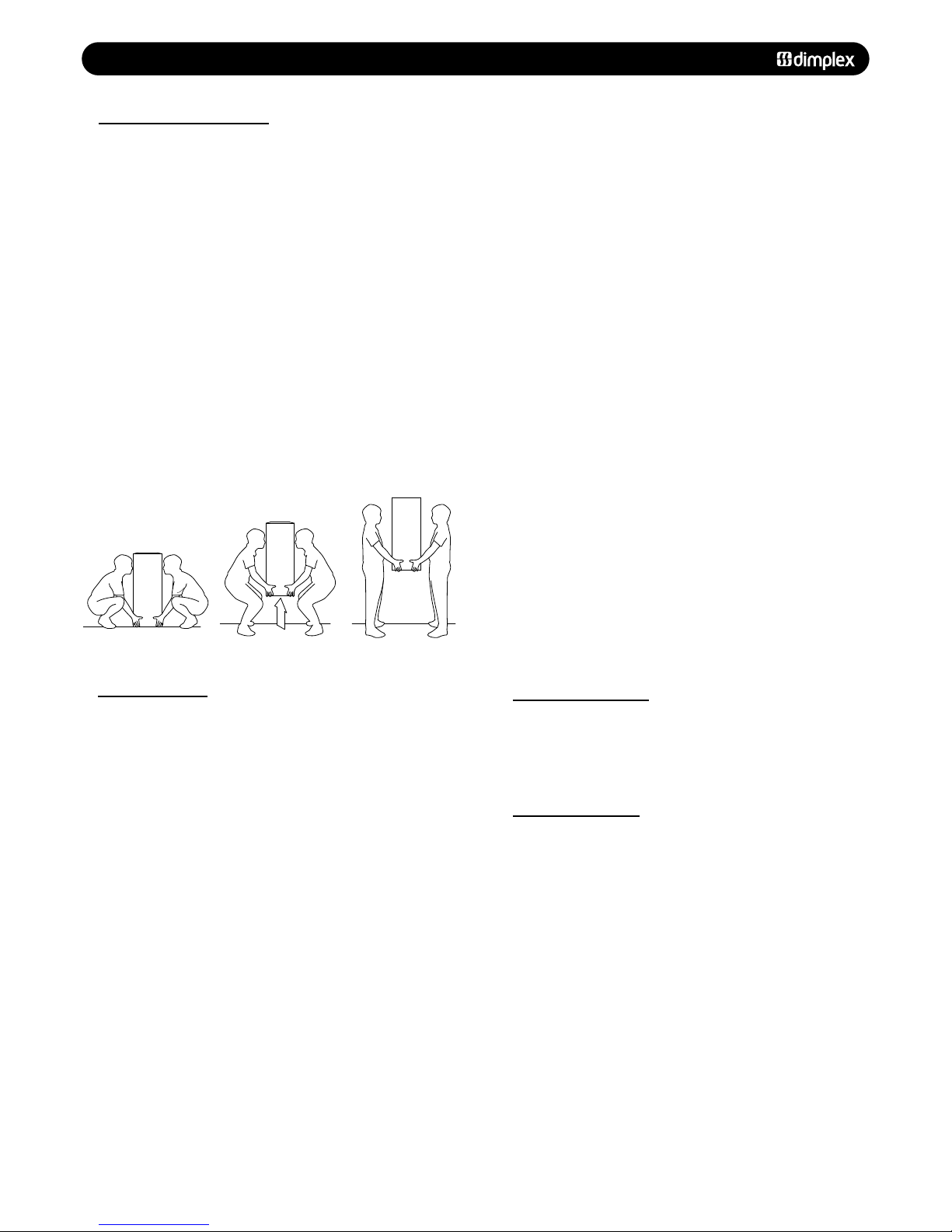
11..44 SSAAFFEE MMAANNUUAALL HHAANNDDLLIINNGG
1. The boiler should be handled and lifted by two people.
Wear appropriate Personal Protection Equipment e.g. protective
gloves, safety footwear etc.
Plan your route to minimise the number of turns needed to
handle/lift the boiler.
2. Where possible transport the boiler using a sack truck or
other suitable trolley. Try to avoid steps, wet or slippery
surfaces, unlit areas etc. and take special care on ladders/into
lofts.
3. When handling or lifting always use safe techniques - keep
your back straight, bend your knees. Don’t twist - move your
feet, avoid bending forwards and sideways and keep the load
as close to your body as possible.
4. Asses the risks associated with handling and lifting
according to the conditions on site. If in doubt seek advice
before proceeding. Health and Safety is the responsibility of
everyone.
Page 7
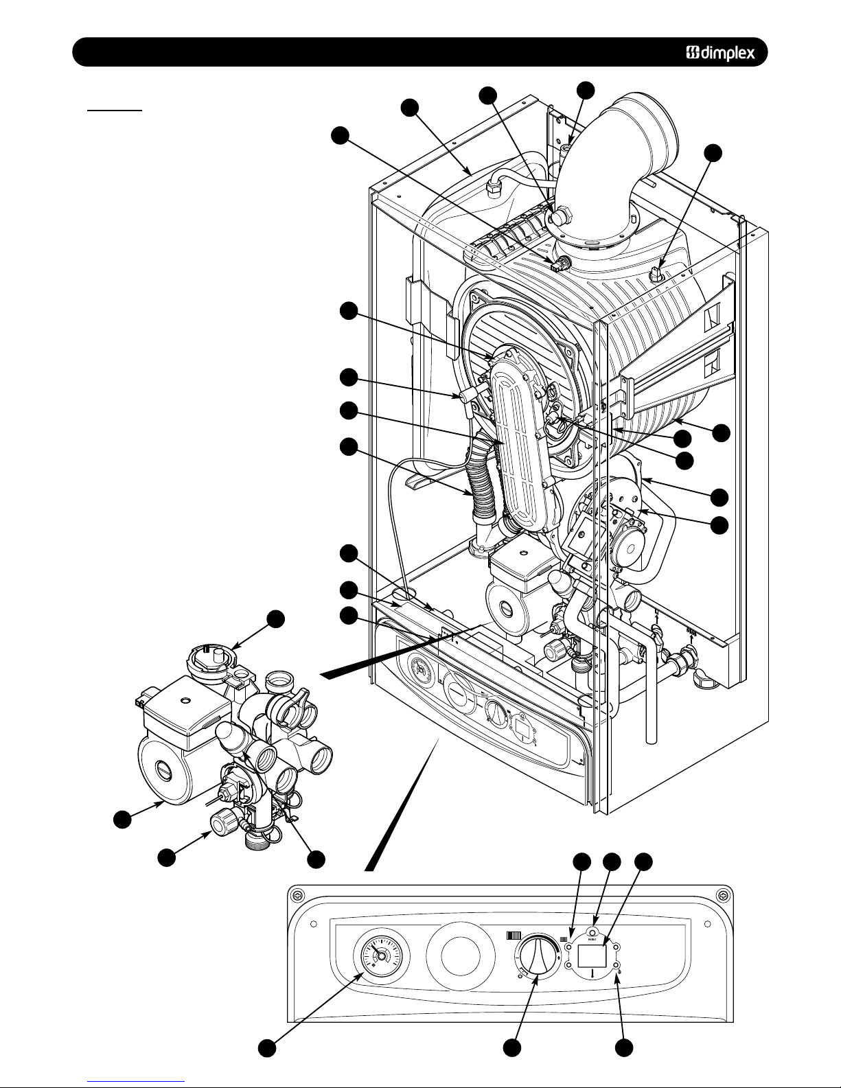
22..00 BBOOIILLEERR LLAAYYOOUUTT
22..11 KKEEYY
1. Expansion Vessel
2. Automatic Air Vent
3. Circulation Pump
4. Drain Off Point
5. Pressure Relief Valve
6. Central Heating System Pressure Gauge
7. PCB
8. Control Box
9. Flexible condensate pipe assembly
10. Flame Sensing Electrode
11.
Spark Electrode
12. Primary Heat Exchanger
13. Fan Assembly
14.
Gas Valve & Swirl Plate Assembly
15. Reset Button
16. Central Heating Temperature Control
17.
Air / Gas Channel
18. Burner & Burner Door
19. Spark Generator
20. Data Badge
21. Flue Sample Point
22. Manual Air Vent
23. Burner On Light
24. Central Heating Mode Light
25.
Di
splay
26. Flue Thermistor
27. Thermal Fuse
© Dimple
x Boiler
s 2008
77
0
1
2
bar
3
4
0
1
2
bar
3
4
FFiigg.. 11
FFiigg.. 22
1
1
221
1
226
6
227
7
222
2
2
2
3
3
6
6
7
7
8
8
220
0
9
9
117
7
110
0
118
8
111
1
113
3
114
4
1155225
5
224
4
116
6
223
3
112
2
119
9
4
4
5
5
Page 8
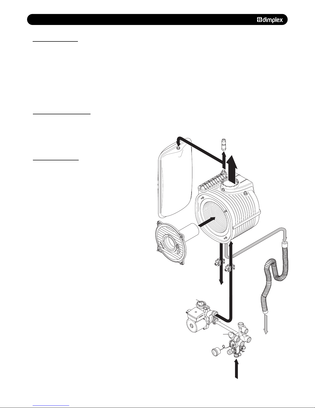
33..00 BBOOIILLEERR OOPPEERRAATTIIOONN
33..11 CCEENNTTRRAALL HHEEAATTIINNGG
1. With a demand for heating, the pump, circulates water
through the primary circuit.
2. Once the main burner ignites the fan speed controls the gas
rate to maintain the heating temperature measured by the
temperature sensors.
3. When the demand is satisfied the burner is extinguished and
a 5 minute delay occurs before the burner will re-light (anticycling), the pump continues to run for a period of 2 minutes
(Pump Overrun).
88
© Dimple
x Boiler
s 2008
33..22 FFRROOSSTT PPRROOTTEECCTTIIOONN MMOODDEE
1. Providing there is mains power supply to the appliance, the frost
protection mode is integral.
If the system temperature falls below 5°C then the boiler will fire on
its minimum se
tting until a flow temperature of 20°C is reached.
Further protection can be incorporated by using a system frost
thermostat.
33..33 PPUUMMPP PPRROOTTEECCTTIIOONN
1. The pump will automatically operate for 1 minute in every 24 hours
to prevent sticking.
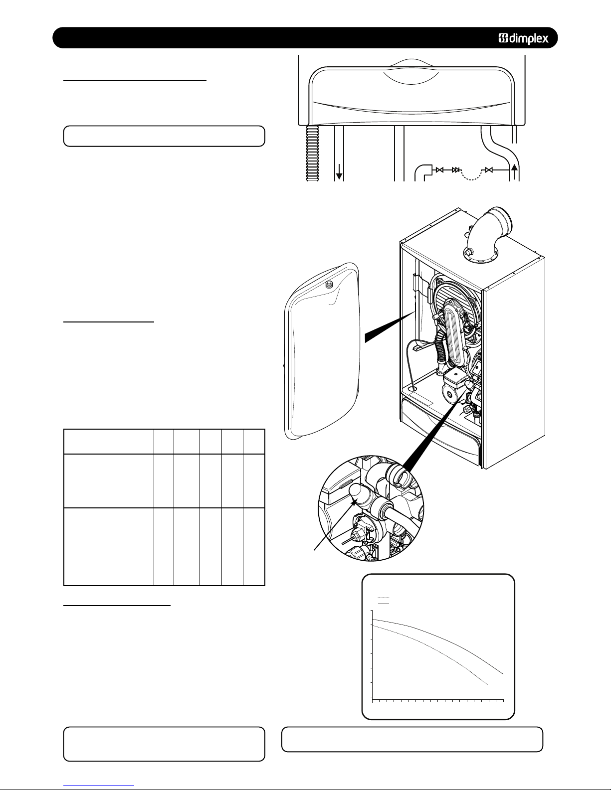
Expansion
V
essel
P
rimary
Heat Exchanger
Burner &
Burner Flange
Primary Return
CH flow
Thermistor
CH return
Thermistor
Condensate
Trap
Pressure
Gauge
CH
Return
3 BAR
Pressure Relief
Valve
Pump &
Hydroblock
Automatic
Air
Vent
CH
Flow
Flue Products
M
anual
Bleed Valve
FFiigg.. 33
Page 9

44..00 TTEECCHHNNIICCAALL DDAATTAA
44..11 PPEERRFFOORRMMAANNCCEE DDAATTAA
© Dimple
x Boiler
s 2008
99
AApppplliiaannccee CCllaassssiiffiiccaattiioonn CC1133,, CC3333,, CC5533,, BB223
3
SSyysstteemm 118
8
SSyysstteemm 330
0
Mode Rate
O
utput (non-condensing)(80-60°C) Max kW 18.1 29.8
Min kW 6.0 8.1
Output (condensing)(50-30°C) Max kW 19.7 32.5
Input Max Rate Net kW 18.4 30.4
G
ross kW 20.4 33.7
Input Min Rate Net kW 5.4 7.6
Gross kW 6.0 8.4
Gas Rate (after 10 min operation - hot) Max m
3
/h 1.95 3.2
Seasonal Efficiency % 90.3 90.3
S
easonal Efficiency (SEDBUK) Band “A” “A”
Nox Classification Class “5” “5”
Min System Pressure Bar 0.5 0.5
Max System Pressure Bar 2.5 2.5
Max Central Heating Flow Temperature °C 80 80
M
in Central Heating Flow Temperature °C 30 30
GGeenneerraall SSppeecciiffiiccaattiioonns
s
Max lift weight kg 33.6 39.6
Total water capacity Ltr 1.8 3.1
I
ntegral expansion vessel capacity Ltr 8 8
Maximum heating system water content using fitted expansion vessel, @ 0.75 bar Ltr 84 84
Electrical supply 240V 50Hz Fuse at 3A
Internal fuse T4H 4A 250V
Maximum power consumption W 100 125
IP Rating IPX4 IPX4
Flue gas temperature 80/60 °C 59 75
Flue gas temperature 50/30 °C 41 55
CO
2
value max rate (Nat Gas) (Case must be fitted when taking reading) % 8.8-9.2 8.8-9.2
CO2value min rate (Nat Gas) (Case must be fitted when taking reading) % 8.5-8.9 8.7-9.1
CO value max rate (Nat Gas) (Case must be fitted when taking reading) P.P.M 15-60 15-60
CO value min rate (Nat Gas) (Case must be fitted when taking reading) P.P.M 0-40 0-40
CO
2
value max rate (Propane) (Case must be fitted when taking reading) % 10.8-11.2 10.5-10.9
CO
2
value min rate (Propane) (Case must be fitted when taking reading) % 10.4-10.8 10.3-10.7
CO value max rate (Propane) (Case must be fitted when taking reading) P.P.M 80-160 80-160
CO value min rate (Propane) (Case must be fitted when taking reading) P.P.M 0-40 0-40
Gas Pressure - Natural Gas mbar 18-20 18-20
Gas P
r
es
sure - Propane mbar 37 37
CCoonnnneeccttiioonns
s
Gas 22 mm compression
CH flow 22 mm compression
CH return 22 mm compression
Pressure relief valve outlet 15 mm compression
Condensate Drain 21.5 - 22 mm plastic overflow pipe
PP..PP..MM == PPaarrttss PPeerr MMiilllliioon
n
Page 10
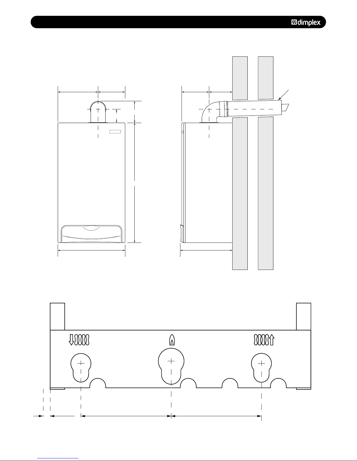
55..00 DDIIMMEENNSSIIOONNSS
1100
© Dimple
x Boiler
s 2008
125mm 125mm
10mm
Condensate
Drain
CH Flow
(22mm)
Gas Inlet
(22mm)
CH Return
(22mm)
Tap Rail
446mm
264mm 182mm
7
96mm
1
50mm
94mm
333mm
148mm185mm
Tube Ø 100mm
FFiigg.. 44
FFiigg.. 55
Page 11

66..00 SSYYSSTTEEMM DDEETTAAIILLSS
66..11 IINNFFOORRMMAATTIIOONN
1. The Dimplex System Boiler is a ‘Water Byelaws Scheme Approved Product’. Reference to the Water Research Council
publications, ‘Water fittings and materials directory’ and ‘Water
supply byelaws guide’ give full details of byelaws and the IRNs.
© Dimple
x Boiler
s 2008
1111
66..33 SSYYSSTTEEMM CCOONNTTRROOLL
1. It
i
s r
ecommended that external controls e.g. room
thermostat are fitted to further improve the operating
efficiency of the boiler and system.
66..22 HHEEAATTIINNGG CCIIRRCCUUIITT
1. The appliance is suitable for fully pumped SEALED SYSTEMS
ONLY.
Treatment of Water Circulating Systems
Failure to flush and add inhibitor to the system will
invalidate the appliance warranty.
• Central heating water systems will be subject to corrosion
unless an appropriate water treatment is applied. This means
that the efficiency of the system will deteriorate as corrosion
sludge accumulates within the system, risking damage to pump
and valves, boiler noise and circulation problems.
• When fitting new systems flux will be evident within the
system, which can lead to damage of system components.
• All systems must be thoroughly drained and flushed out.
Using, for example Betz-Dearborn Sentinel X300 or X400 or
Fernox Superfloc Universal Cleanser. They should be used
following the flushing agent manufacturer’s instructions.
• System additives - corrosion inhibitors and flushing
agents/descalers should comply to BS7593 requirements, e.g.
Betz-Dearborn Sentinel X300 and Fernox-Copal which should
be used following the inhibitor manufacturer’s instructions.
• It is important to check the inhibitor concentration after
installation, system modification and at every service in
ac
cor
dance with the manufacturer’s instructions. (Test kits are
available from inhibitor stockists.)
• F
or information or advice regarding any of the above contact
Technical Enquiries - Tel: 0844 3711121.
• If thermostatic radiator valves are fitted, a radiator must be
fitted with two lock shield valves or the system must include a
proprietary automatic bypass valve, to enable correct operation
of the pump o
v
er-run
f
acility.
Page 12
66..00 SSYYSSTTEEMM DDEETTAAIILLSS
66..44 SSYYSSTTEEMM FFIILLLLIINNGG AANNDD PPRREESSSSUURRIISSIINNGG
1. A filling point connection on the central heating return
pipework must be provided for initial filling and pressurising
and subsequent topping up of the system.
A filling loop is provided loose with the boiler
2. The filling method adopted must comply with all relevant
water supply regulations and use approved equipment.
3. Further details are given in;
for GB: Guidance G24.2 and recommendation R24.2 of the
Water Regulations Guide.
f
or IE: the current edition of I.S. 813 “Domestic Gas
Installations”.
4. The sealed primary circuits may be filled or topped up using
a temporary connection between the circuit and a supply pipe,
provided a ‘Listed’ double check valve or some other no less
effective backflow prevention device is permanently connected
at the inlet to the circuit and the temporary connection is
removed after use.
1122
© Dimple
x Boiler
s 2008
66..55 EEXXPPAANNSSIIOONN VVEESSSSEELL
1. The appliance expansion vessel is pre-charged to 1 bar.
Therefore the minimum cold fill pressure is 2 bar. The vessel is
suitable for correct operation for system capacities up to 84
litres. For greater system capacities an additional expansion
vessel must be fitted.
For GB refer to BS 7074 Pt 1.
For IE, the current edition of I.S. 813 “Domestic Gas
Installations”.
66..66 PPRREESSSSUURREE RREELLIIEEFF VVAALLVVEE
1. The pressure relief valve is set at 3 bar, therefore all
pipew
ork,
fit
tings, etc. should be suitable for pressures in
excess of 3 bar and temperature greater than 100°C.
2. The pressure relief discharge pipe should be not less than
15mm diameter, run continuously downward, and discharge
outside the building, preferably over a drain. It should be
r
out
ed in such a manner
tha
t
no hazar
d occurs to occupants or
causes damage to wiring or electrical components. The end of
the pipe should terminate facing down and towards the wall.
NNOOTTEE:: BBooiilliinngg wwaatteerr//sstteeaamm ccoouulldd ddiisscchhaarrggee ffrroomm tthhee ppiippee,,
tthheerreeffoorree iitt sshhoouulldd bbee tteerrmmiinnaatteedd aawwaayy ffrroomm wwiinnddoowwss aanndd
ddoooorrss..
Mains
Supply
CH
Return
Pressure
Relief
Discharge
Pipe
Temporary
Loop
Stop
Valve
Stop
Valve
Double
Check
Valve
GasCH
Flow
Condensate
1
0 1 2 3 4 5 6 7 8 9 10 11 12 13 14 15 16 17 18
2
3
4
5
6
7
FLOW RATE Ltr/min
PUMP HEAD (mH
2
O)
System 18
System 30
AVAILABLE PUMP HEADS
FFiigg.. 88
FFiigg.. 77
Expansion Vessel
P
ressure
R
elief V
alve
Vessel charge and initial
sy
s
t
em pressure
Total water content of
system using 8 litres
capacity expansion
vessel supplied with
appliance
For systems having a
larger capacity multiply
the t
otal system capacity
in litres by this factor to
obtain the total minimum
expansion vessel capacity
required in litres
bar
litres
0.5960.75
84
0.093
1.0731.5
50
FFiigg.. 66
FFiigg.. 99
FFiigg.. 1100
NNOOTTEE:: DDoo nnoott uussee tthhee pprreessssuurree rreelliieeff vvaallvvee ttoo ddrraaiinn tthhee ssyysstteemm,, bbeeccaauussee ddiirrtt
aanndd ddeebbrriiss ccoouulldd pprreevveenntt tthhee vvaallvvee sseeaattiinngg ccoorrrreeccttllyy..
Page 13
77..00 SSIITTEE RREEQQUUIIRREEMMEENNTTSS
77..11 LLOOCCAATTIIOONN
1. The boiler may be fitted to any suitable wall with the flue
passing through an outside wall or roof and discharging to
atmosphere in a position permitting satisfactory removal of
combustion products and providing an adequate air supply. The
boiler should be fitted within the building unless otherwise
protected by a suitable enclosure i.e. garage or outhouse. (The
boiler may be fitted inside an unvented cupboard - see section
7.3).
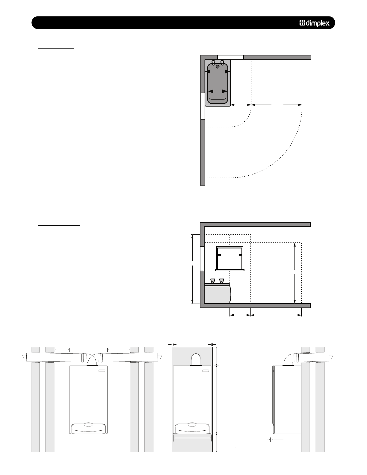
2. If the boiler is fitted in a room containing a bath or shower
reference must be made to the relevant requirements.
In GB this is the current I.E.E. Wiring Regulations and Building
R
egulations.
In IE reference should be made to the current edition of I.S.
813 “Domestic Gas Installations” and current ETCI rules.
(Fig. 11 shows zone dimensions for a bathtub. For other
examples refer to Section 601 of the current I.E.E. Wiring
Regulations) reference must be made to the relevant
requirements.
The boiler is IPX4 rated and can be fitted in Zone 2 (Fig. 11).
3. If the boiler
is to be fitted into a building of timber frame
construction then reference must be made to the current
edition of Institute of Gas Engineers Publication IGE/UP/7 (Gas
Installations in Timber Framed Housing).
© Dimple
x Boiler
s 2008
1133
77..22 CCLLEEAARRAANNCCEESS
1. A flat vertical area is required for the installation of the
boiler.
2. These dimensions include the necessary clearance around
the boiler for case removal, spanner access and air movement.
Additional clearances may be required for the passage of pipes
around local obstructions such as joists running parallel to the
f
r
ont face of the boiler.
Zone 2
Zone 2
Zone 1
Zone 0
Zone 3
Zone 3
Window Recess
Zone 2
Window
Recess
Zone 2
0.6 m 2.4 m
Zone 2 Zone 3
Zone 2Zone 1
Zone 0
Zone 3
Outside Zones
Ceiling
Window
Recess
Zone 2
3.0 m
2.25 m
0.6 m 2.4 m
285mm Wall
450mm Min
For Servicing
Purposes
5mm Min
In Operation
5mm Min
446mm
5mm Min
796mm
200mm
200mm
5mm Min
5mm Min
285mm Wall
285mm Wall
FFiigg.. 1111
FFiigg.. 1122
Page 14
77..00 SSIITTEE RREEQQUUIIRREEMMEENNTTSS
77..33 VVEENNTTIILLAATTIIOONN OOFF CCOOMMPPAARRTTMMEENNTTSS
1. Where the appliance is installed in a cupboard or
compartment, no air vents are required.
Where an open flued system is used - Flue kit E (B23
classification) then an air vent communicating directly with
outside air must be provided in the same room or internal
space of the flue duct air inlet. Minimum free area:
System 18 = 88cm
2
System 30 = 159cm
2
In addition if an open flued system is used - Flue kit (B23
classification) and the boiler is fitted in a compartment, then
high and low le
vel ventilation is required.
BS 5440-2:2000 gives guidance on compartmental ventilation.
2. When the boiler is installed in a cupboard or compartment
and either flue kit A, B, C, D or F (Classification C13, C33, C53)
is used, then no compartmental ventilation is required.
1144
© Dimple
x Boiler
s 2008
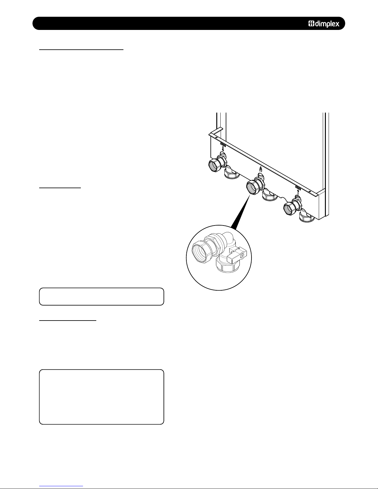
77..44 GGAASS SSUUPPPPLLYY
1. The gas installation should be in accordance with the
relevant standards. In GB this is BS 6891. In IE this is the
current edition of I.S. 813 “Domestic Gas Installations”.
2. The connection to the appliance is a 22mm copper tail
located at the rear of the gas service cock (Fig. 13).
3. Ensure that the pipework from the meter to the appliance is
of adequate size, and the demands of any other gas appliance
in the property are taken into consideration. Do not use pipes
of a smaller diameter than the boiler gas connection (22mm).
4. For boilers connected to use LPG (propane), the inlet
pressure must be 37mbar.
NNOOTTEE::
The comple
ted installation should always be tested
for gas tightness
77..55 EELLEECCTTRRIICCAALL SSUUPPPPLLYY
1. External wiring must be correctly earthed, polarised and in
accordance with relevant regulations/rules. In GB this is the
current I.E.E. Wiring Regulations. In IE reference should be
made t
o the cur
r
en
t
edition of the ET
GI rules.
2. The mains supply is 230V - 50Hz fused at 3A
NNOOTTEE::
The mains supply connection must allow complete
electrical isolation of the appliance and system controls
only.
Connection may be via a fused double-pole isolator with a
contact separation of at least 3mm in all poles and servicing
the boiler
and sy
s
t
em con
t
rols only.
Any additional mains cable should comply fully with the
current I.E.E. wiring regulations.
FFiigg.. 1133
Gas Serv
ice
Cock
Page 15
77..00 SSIITTEE RREEQQUUIIRREEMMEENNTTSS
77..66 CCOONNDDEENNSSAATTEE DDRRAAIINN
NNOOTTEE::
The appliance is fitted with a trap the depth of
which is >= 75mm, therefore no other traps are required in
the condensate run.
The condensation discharge pipe must not rise at any point
along its length. There MUST be a fall of AT LEAST 2.5° (50mm
per metre) along the entire run.
1. The condensate outlet will accept 21.5mm (3/4in) plastic
overflow pipe which should discharge internally into the
household drainage system, downstream of all other traps. if
this is not possible, discharge into an outside drain is
ac
ceptable.
2. Ensure the discharge of condensate complies with any
national or local regulations in force.
BBSS 66779988::22000000 && PPaarrtt HHII ooff tthhee BBuuiillddiinngg RReegguullaattiioonnss ggiivvee
ffuurrtthheerr gguuiiddaannccee..
3. Metal pipework is NOT suitable for use in condensate
discharge systems.
4. The pipe should be a minimum of 21.5mm diameter and
must be supported properly.
5.
IItt iiss aaddvviissaabbllee ttoo kkeeeepp tthhee ccoonnddeennssaattee ppiippee iinntteerrnnaall..
6.
EExxtteerrnnaall rruunnss ggrreeaatteerr tthhaann 33 mmeettrreess oorr rruunnss iinn ccoolldd aarreeaass
sshhoouulldd uussee 3322mmmm wwaassttee ppiippee aanndd bbee iinnssuullaatteedd..
7. If the boiler is fitted in an unheated location the entire
condensate discharge pipe should be treated as an external
run.
8. In all cases discharge pipe must be installed to aid disposal
of the condensate.
9. When discharging condensate into a soil stack or waste pipe
the effects of existing plumbing must be considered. If soil
pipes or waste pipes are subjected to internal pressure
fluctuations when WC’s are flushed or sinks emptied then
back-pressure may force water out of the boiler trap and
cause appliance lockout.
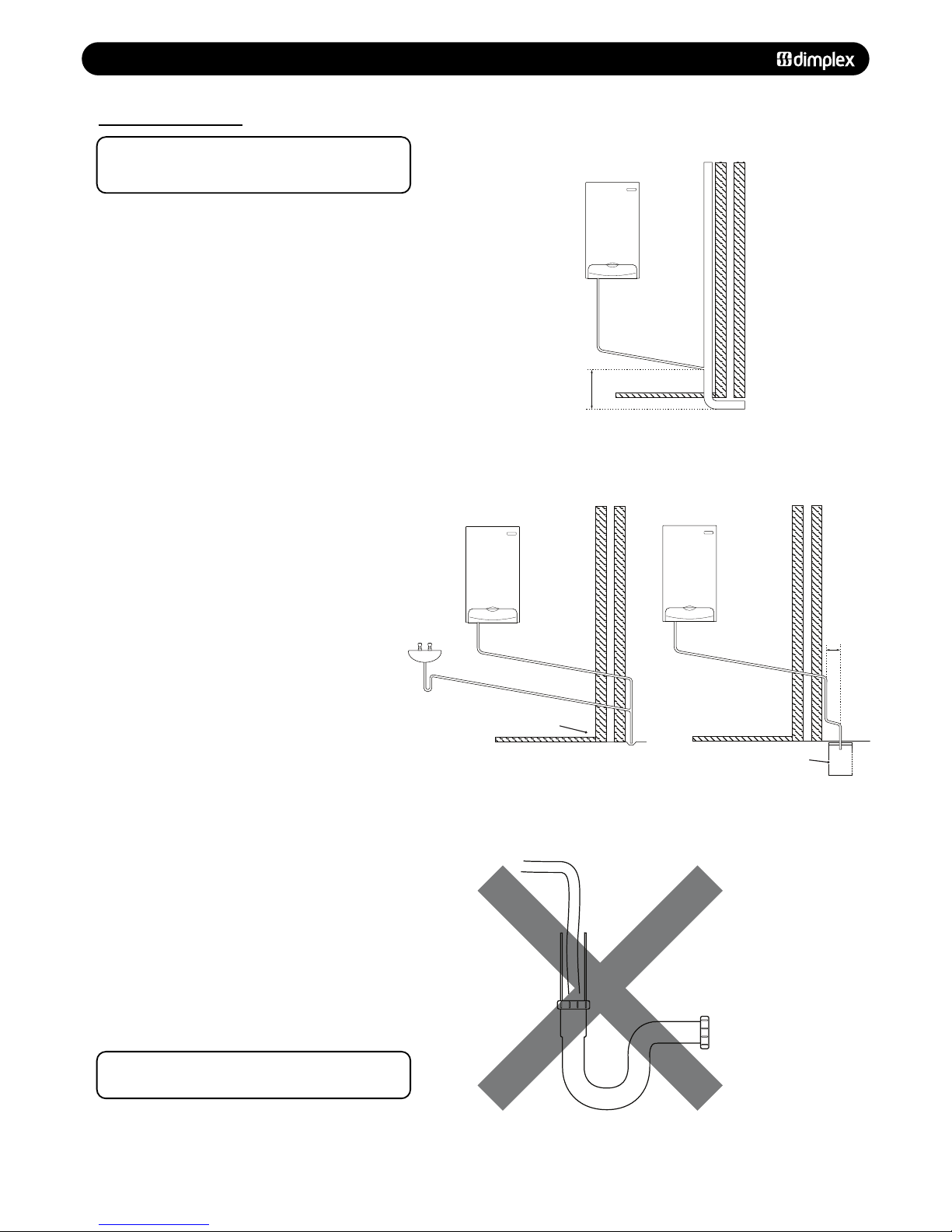
Ex
amples ar
e shown of the
f
ollowing methods of terminations
(se
e figs. 14,15 & 16):
i) to an internal soil & vent pipe
ii) via and internal discharge branch (e.g. sink waste)
iii) to a drain or gully
i
v) to a purpose made soakaway
10. In e
x
ceptional circumstances, such as when a boiler is
installed in a basement without drainage, it may be necessary
t
o ins
t
all a condensate pump to carry condensate up to ground/
d
r
ain le
v
el. Such pr
oducts ar
e a
v
ail
able
from most plumbing
merchants. For help with selecting a condensate pump contact
Dimplex Boilers - Tel: 0844 3711121.
WWAARRNNIINNGG::
There must be no air breaks in the condensate
pipework or drainage system (see Fig. 17).
© Dimple
x Boiler
s 2008
1155
5
0
mm p
e
r me
tre
o
f p
ip
e
r
u
n
2.5° Minimum fall
4
50mm min
T
ermination to an internal soil and vent pipe
50mm per metre of pipe r
un
2.5° Minimum fall
External termination via internal discharge branch
e
.g sink waste - downstream
Sink
Pipe must terminate
above water level but
below surrounding surface.
50mm per metre of pipe r
un
2.5° Minimum fall
Termination to a purpose made soak-away
Holes in the soak-away must
face away from the building
500mm min
NNOOTT AALLLLOOWWEEDD
TThheerree sshhoouulldd bbee
nnoo aaiirr ggaap
p
FFiigg.. 1144
FFiigg.. 1155
FFiigg.. 1177
FFiigg.. 1166
Page 16

77..00 SSIITTEE RREEQQUUIIRREEMMEENNTTSS
77..77 FFLLUUEE
1. This high efficiency boiler will discharge a plume of water
vapour from the flue. This should be considered when siting
the flue terminal.
2. The following guidelines indicate the general requirements
for siting balanced flue terminals. For GB recommendations are
given in BS 5440 Pt 1. For IE recommendations are given in
the current edition of I.S. 813 “Domestic Gas Installations”.
3. If the terminal discharges onto a pathway or passageway,
check that combustion products will not cause a nuisance and
that the terminal will not obstruct the passageway.
4. If a terminal is less than 2 metres above a balcony,above
ground or above a flat roof to which people have access, then
a suitable terminal guard must be provided - Part No: 951507.
IIMMPPOORRTTAANNTT::
• Only
OONNEE
of the 25mm clearances (Positions ‘O’ to ‘S’ in
the chart below) is allowable per installation.
• Under car ports we recommend the use of the plume
displacement kit.
• The terminal position must ensure the safe and nuisance
- free dispersal of combustion products.
1166
© Dimple
x Boiler
s 2008
NNOOTTEE:: TThhee mmiinniimmuumm ddiissttaannccee ffrroomm aa fflluuee tteerrmmiinnaall ttoo aa bboouunnddaarryy lliinnee iiss 330000mmmm..
IIff ffiittttiinngg aa pplluummee ddiivveerrtteerr kkiitt,, tthhee aaiirr iinnlleett sshhoouulldd bbee aa mmiinniimmuumm ooff 110000mmmm ffrroomm
aannyy ooppeenniinngg wwiinnddoowwss oorr ddoooorrss..
NNOOTTEE AA:: AA tteerrmmiinnaall sshhoouulldd
bbee nnoo cclloosseerr tthhaann 115500mmmm
ttoo aann ooppeenniinngg iinn tthhee
bbrriicckkwwoorrkk iinntteennddeedd ttoo
aaccccoommmmooddaattee aa ffiittttiinngg
ssuucchh aass aa wwiinnddooww ffrraammee..
NNOOTTEE:: FFiittttiinngg ooff tthhee ddeefflleeccttoorr
eellbbooww iiss rreeccoommmmeennddeedd wwhheenn
iinnssttaalllliinngg bbooiilleerr ttoo mmiinniimmuumm
cclleeaarraannccee ooff 2255mmmm aass
ddeettaaiilleedd iinn ppoossiittiioonnss OO && PP..
A
M,L
M,L
N
C
F
P
O
O
R
N
S
C
C
N
Flue terminals that require a guard fitting
P
B
J
H
N
N
G
Q
K
D
E
PPoossiittiioon
n
DDeessccrriippttiioon
n
MMiinniimmuumm DDiissttaannccee ((mmmm)
)
A Horizontally to an opening, air brick, opening window - see note A 300
B
A
bo
ve an opening, air brick, opening window etc. - see note A 300
C
Below an opening, air
brick, opening window e
tc. - see note A 300
D Below windows or openings on pitched roofs 2000
E
A
djac
ent to windows or openings on pitched and flat roofs 600
F
F
r
om an adjacent opening window (vertical only) 1000
G From an adjacent wall to flue (vertical only) 300
H
Horiz
ontally from a terminal on the same wall 300
J
V
ertically from a terminal on the same wall 1500
K From an opening in a carport (e.g. door, window) into the dwelling 1200
L
From a terminal facing a terminal (horizontal flue) 1200
F
rom a terminal facing a terminal (vertical flue) 600
M
From a surface or boundary line facing a terminal 600
N Above ground, roof or balcony level 300
O From an internal or external corner 25
P From a vertical drain pipe or soil pipe 25
Q Below balconies or car port roof 25
R Below eaves 25
S Below gutters, soil pipes or drain pipes 25
300mm Min 300mm Min
Adjoining Properties Boundary Line
TTEERRMMIINNAALL PPOOSSIITTIIOONN
FFiigg.. 1188
FFiigg.. 1199
Page 17

88..00 FFLLUUEE OOPPTTIIOONNSS
© Dimple
x Boiler
s 2008
1177
88..11 CCOONNCCEENNTTRRIICC AAIIRR//FFLLUUEE DDUUCCTT SSPPEECCIIFFIICCAATTIIOONNSS
The different flue applications shown in Fig. 20 are available as
kits comprising the connecting parts to the appliance and end
terminal. Flue extension ducts and extension elbows are
available as accessories.
88..22 KKiitt AA ++ TTeelleessccooppiicc HHoorriizzoonnttaall WWaallll TTeerrmmiinnaall
((CC1133)) -- PPaarrtt NNoo.. 995566112200
60/100mm concentric, horizontal flue system Fig. 21, with a
maximum length of 10M.
The standard telescopic terminal is 615mm max length and
430mm min length, but can be cut to a minimum flue length of
250mm, which is suitable for single, 100mm (4”), brick walls.
NNoottee::
If the telescopic flue kit is installed without any flue
extensions, it can be fitted horizontally. The maximum
length for 60/100mm horizontal concentric flue = 10M
NNoottee::
Dimplex System 18 only, with maximum concentric
flue length of 10m, the heat input will be reduced by 7.6%
88..33 KKiitt BB VVeerrttiiccaall CCoonncceennttrriicc FFlluuee TTeerrmmiinnaall
((CC3333)) -- HHBBLL PPaarrtt 995566008811
60/100mm concentric, vertical flue system, Fig. 22, with a
maximum length of 12M.
The kit comprises of the roof terminal, vertical adaptor with
sampling point and bracket.
The ma
ximum length i
s me
asur
ed
f
rom the top of the
appliance casing to the underside of the air cowl.
For installation details refer to the flue kit instructions.
Chimney flue liner kit
- Part no. 956082
Vertical flue kit - Part no. 956081
V
ertical flue kit - Part no. 956081
with flat roof flashing plate
Split pipe vertical flue outlet kit
- Part no. 956080
with flat roof flashing plate
Raised external flue outlet kit
- Part no. 956084
Vertical flue kit - Part no. 956081
External vertical flue kit
- Part no. 956085
S
tandard telescopic
horizontal flue kit
- Part no. 956120
O
ptional Flue Systems
The pluming from the flue may
cause nuisance to neighbours
or other buildings.
60/100 flue accessories:
0.5m flue extension duct - 956092
1m flue extension duct - 956093
9
3 flue extension elbow - 956091
4
5 flue extension elbow (2x) - 956090
Vertical flue turret - 956087
Ø60/100mm concentric
standard horizontal wall
terminal.
M
ax. length 10,000mm.
M
in. length 250mm.
Standard telescopic horizontal flue kit - Part no. 956120
H
orizontal terminal has a
built-in fall in the flue to allow
condensate to drain away.
If horizontal flue requires
extension pipe. the flue
should be installed such
that there is no section less than
1
.5° - 3° to the horizontal,
falling back towards the boiler.
9
3 flanged elbow (concentric)
with sampling point
Kit A +
Vertical flue kit - Part no. 956081
Suitable for 25 - 45°
Pitch Angle
Length
Kit B
60/100 flue accessories:
0.5m flue extension duct - 956092
1m flue extension duct - 956093
93 flue extension elbow - 956091
45 flue extension elbow (2x) - 956090
Pitched roof flashing kit - 956089
Flat roof flashing plate - 840512
93 flanged flue elbow - 956086
Max. length12m.
Min. length 0.6m.
Roof terminal
with rain cover
and pitched roof
flashing kit.
Vertical flue socket
with sampling point.
Top of Boiler
to underside of Cowl
FFiigg.. 2200
FFiigg.. 2211
FFiigg.. 2222
Page 18

88..00 FFLLUUEE OOPPTTIIOONNSS
1188
© Dimple
x Boiler
s 2008
88..55 KKiitt CC HHoorriizzoonnttaall AAnnttii--PPlluummee FFlluuee KKiitt
((CC1133)) -- PPaarrtt NNoo.. 995566008844
This kit is recommended if the condensate plume from the flue
may cause a nui
sance or affect the surroundings. The air inlet
remains outside and the flue duct is routed separately using a
60mm duct enclosed by a protective 80mm tube. To calculate
the maximum lengths of 60/100 concentric flue and 60mm
flue ducts, use the table below.
For installation details refer to the flue kit instructions.
Dimensions from vertical terminals to opening windows should
be in line with Fig. 19.
(For use with Standard horizontal telescopic flue kit - Part no.
956120 - only).
This kit is useful for deflecting the condensate plume away
from walls or boundaries. It should only be used to deflect the
condensate plume left or right.
60/100mm concentric vertical flue system.
Maximum length = 12m. The flue kit contains two additional
45° elbows and 2.5 metres of 60/100 concentric ducts as well
as a special wall bracket to pass the guttering (see Fig. 26).
The conc
en
t
ric
flu
e will be routed vertically alongside the
outside wall to above the roofline. Special seals are required to
prevent rainwater penetrating the pipe joints.
F
or installation details refer to the flue kit instructions.
88..66 PPlluummee DDiivveerrtteerr TTeerrmmiinnaall KKiitt
PPaarrtt NNoo.. 995566110033
88..77 KKiitt DD EExxtteerrnnaall VVeerrttiiccaall FFlluuee
((CC3333)) -- PPaarrtt nnoo.. 995566008855
9
3 flanged elbow (concentric)
w
ith sampling point
R
aised external flue outlet kit -
Part no. 956084
Kit C
Raised Ø60mm flue
outlet duct with
Ø
80mm anti-freeze
pipe.
Max height of raised
flue from top of boiler
to centre of outlet 8.5m
M
in height 1m.
93 flanged elbow (concentric)
with sampling point
Max. lengths (from top of
boiler to AIR COWL 12m
Min. length 1m.
Kit D
Ø60/100mm concentric
air/flue pipe Part no. 956093
(1m extension)
and
Part no, 956092
(0.5m extension)
For outside installations
the pipe joints have to
be covered with special
“lip-seal” to prevent
rain ingress.
Ensure all horizontally fitted
pipes are routed with a
1.5-3° fall towards the boiler.
External vertical flue kit - Part no. 956085
Roof terminal
with rain cover.
88..44 TToottaall EEqquuiivvaalleenntt LLeennggtthhss ffoorr CCoonncceennttrriicc
((6600//110000mmmm)) fflluuee ssyysstteemmss
FFiigg.. 2244
FFiigg.. 2233
FFiigg.. 2255
FFiigg.. 2266
CCoommppoonneenntt
45° Bend
93° Bend
0.5m Extension
1.0m Extension
Support Bracket
EEqquuiivvaalleenntt lleennggtthh iinn mmeettrreess
0.5m
1.0m
0.5m
1.0m
N/A
PPaarrtt nnuummbbeerr
956090 - 2 off
956091
956092
956093
840517
CCoonncceennttrriicc ((6600//110000mmmm))
fflluuee lleennggtthh ((mmeettrreess))
00..33 00..55
4455°° BBeenndd
11..00 11..55 22..00 22..55 33..00 33..55 44..00 44..55 55..00
MMaaxxiimmuumm ((6600//8800mmmm)) fflluuee
lleennggtthh aalllloowweedd ((mmeettrreess))
99..22
EExxaammppllee:: IIff rreeqquuiirreedd lleennggtthh ooff 6600//110000mmmm ccoonncceennttrriicc == 11mm
tthheenn mmaaxxiimmuumm 6600//8800 lleennggtthh == 88..55mm
99..00 88..55 88 77..55 77 66..55 66 55..55 55 44..55
SSuuppppoorrtt BBrraacckkeett
9933°° BBeenndd
00..55mm EExxtteennssiioonn
11..00mm EExxtteennssiioonn
Page 19

88..00 FFLLUUEE OOPPTTIIOONNSS
© Dimple
x Boiler
s 2008
1199
88..88 KKiitt EE CChhiimmnneeyy FFlluuee LLiinneerr KKiitt
((BB2233)) -- PPaarrtt nnoo.. 995566008822
NNoottee::
Dimplex System 18 and 30: Maximum flue length = 30m.
Minimum length for all Dimplex System boilers = 5m.
This kit is suitable for open flue application in accordance with
BS5440 parts 1 & 2 where a room sealed flue installation is
impractical. The kit comprises of a flue adaptor from the
appliance to the chimney, a flexible plastic flue liner with
connection parts and chimney terminal (see Fig. 27). Further
guidance on ventilation requirements is given in section 7.3.
See ‘Total equivalent lengths for concentric (60/100mm) flue
systems’
88..1100 KKiitt FF:: TTwwiinn FFlluuee SSyysstteemm
((CC5533)) -- PPaarrtt nnoo.. 995566008800
NNoottee::
Maximum flue length (air duct + flue duct) = 38m.
Minimum
flue length (air duct + flue duct) = 10m.
The kit
compri
ses of a twin adapt
or suitable for 80mm ducts,
from which the air intake is taken from the adjacent outside
wall (see Fig. 28) and the flue duct is routed vertically through
the roof.
It
i
s
nnoott
r
ecommended t
o r
out
e the
flue duct through living
spac
e areas, i.e. bedrooms, living rooms etc.
For installation details refer to the instructions provided with
the twin flued kit.
Centralising brackets
Chimney terminal
93 flanged elbow (concentric)
with sampling point
Ø60/100mm concentric
chimney adaptor pipe.
T
he chimney must be swept
a
nd cleared of any debris
a
nd obstructions.
Chimney
p
late
Flexible corrugated plastic flue liner
Ø80mm according to EN 14471
Max. length 30m.
Min. length 5m.
KIT E
Chimney flue liner kit - Part no. 956082
Ø80mm air intake
Split flue system
Roof terminal with pitched
roof flashing kit.
If the flue pipe passes
through compartment
from wall/floors, the
requirements set out
in Building Regulations
Part B must be followe
d.
Ø80mm twin adaptor
with sampling point.
If the flue pipe are boxed in then
access must be provided to inspect
the flue ducts during installation
and subsequent service visits.
The access panels and flue boxing
should be sealed from the room.
Split pipe vertical
flue outlet kit Part no. 956080
Kit F
FFiigg.. 2277
FFiigg.. 2288
CCoommppoonneenntt
90° Bend
45° Bend
1.0m Extension
2.0m Extension
EEqquuiivvaalleenntt lleennggtthh iinn mmeettrreess
AAiirr DDuucctt
4.0m
2.0m
1.0m
2.0m
FFlluuee DDuucctt
8.0m
4.0m
2.0m
4.0m
PPaarrtt nnuummbbeerr
956100
956099
956101
956102
88..99 KKiitt EE:: KKeeyy fflluuee ddiimmeennssiioonnss ++ AAcccceessssoorriieess
Minimum length 60/100mm horizontal flue 100mm From boiler to chimney
Maximum length 60/100mm horizontal flue 2000mm From boiler to chimney
Minimum length 60/100mm vertical flue 200mm From boiler to chimney
Maximum length 60/100mm vertical flue 2000mm From boiler to chimney
Minimum length 80mm flue liner 5000mm From adaptor to chimney terminal
Maximum length 80mm flu
e liner
30000mm
From adaptor to chimney terminal
AAcccceessssoorry
y
LLeennggtth
h
PPaarrtt NNuummbbeer
r
80mm Fle
xitube
flue liner 10m 956110
80mm Flexitube flue liner 20m 956111
80mm Flexitube flu
e liner 30m 956112
Boiler vertical flue adaptor/turret socket N/A 956087
Page 20

99..00 IINNSSTTAALLLLAATTIIOONN
99..11 UUNNPPAACCKKIINNGG && IINNIITTIIAALL PPRREEPPAARRAATTIIOONN
TThhee ggaass ssuuppppllyy,, ggaass ttyyppee aanndd pprreessssuurree mmuusstt bbee cchheecckkeedd ffoorr
ssuuiittaabbiilliittyy bbeeffoorree ccoonnnneeccttiioonn
1. Remove the top cardboard tray from the carton.
2. The wall fixing jig is packed in its own cardboard sleeve.
Carefully slide this out of the carton.
3. To avoid scratching the boiler outercase, keep the outer
carton in place.
4. After reviewing the site requirements (see Section 7.0),
pos
ition the fixing template on the wall ensuring it is level both
horizontally and vertically.
5. Mark the position of the fixing holes for the wall plate and
boiler lower fixing holes.
6. Mark the position of the centre of the flue hole (rear exit).
For side flue exit, mark as shown (Fig. 4).
7. If r
equired, mark the position of the gas and water pipes.
Remove the template.
8. Cut the hole for the flue (minimum diameter 110mm).
9. Drill the wall as previously marked to accept the wall plugs
supplied. Secure the wall fixing jig using the fixing screws.
10. Using a spirit level ensure that the fixing jig is level before
finally tightening the screws.
11. Flush and clean the system using an appropriate cleanser
(Fig. 30).
12. Connect the gas and water pipes to the valves on the wall
fixing jig.
13. Fit the filling loop as described in the instructions supplied
with it.
2200
© Dimple
x Boiler
s 2008
FFiigg.. 3300
Flushing Pipe
C
en
tral Heating Flow
or Return Pipe
FFiigg.. 2299
Page 21

99..00 IINNSSTTAALLLLAATTIIOONN
99..22 FFIITTTTIINNGG TTHHEE BBOOIILLEERR
1. Remove the sealing caps from the boiler connections.
NOTE: A small amount of water may drain from the boiler
once the caps are removed.
2. Check the sealing washers are located correctly in the taps
on the wall jig.
3. Lift the boiler as indicated by the shaded areas. The boiler
should be lifted by TWO PEOPLE. Engage the slots at the top
rear of the boiler on the wall plate (Fig. 31) (see
SSaaffee MMaannuuaall
HHaannddlliinngg
page 6).
4. Ensure the boiler is correctly located on the wall jig and the
connections align. Tighten all the connections.
© Dimple
x Boiler
s 2008
2211
99..33 FFIITTTTIINNGG TTHHEE PPRREESSSSUURREE RREELLIIEEFF DDIISSCCHHAARRGGEE PPIIPPEE
1. Remove the two screws securing the front panel to the
underside of the boiler. Rotate the bottom of the panel out
slightly and lift the panel upwards off its retaining studs on top
of the appliance.
2. Determine the route of the discharge pipe.
3. Taking care not to disturb the case sealing grommet, the
pipework must be at least 15mm diameter and run
continuously downwards to a discharge point outside the
building.
4. Complete the discharge pipework and route it to the outside
discharge point.
99..44 CCOONNDDEENNSSAATTEE DDRRAAIINN
1. Connect the condensate drain to the trap outlet pipe.
Ensure the discharge of condensate complies with any
national or local regulations in force.
2. The connection will accept 21.5 - 22mm plastic overflow
pipe which should g
ener
ally di
schar
ge internally into the
household drainage system. If this is not possible, discharge
into an outside drain is acceptable.
FFiigg.. 3333
Pressure Relief
Di
schar
g
e Pipe
Front Panel
Retaining Stud
XX 22
XX 22
FFiigg.. 3311
FFiigg.. 3322
Page 22

99..00 IINNSSTTAALLLLAATTIIOONN
99..55 FFIITTTTIINNGG TTHHEE FFLLUUEE
HHOORRIIZZOONNTTAALL TTEELLEESSCCOOPPIICC FFLLUUEE
1. For correct flue installation please refer to the installation
instructions that are provided with the individual flue kit as
described in sections 7 & 8.
2. Measure the required flue length as shown in Fig. 34. Refer
to section 8 to determine whether any extension kits are
required. Installations using only the standard ducts or
standard ducts with straight extensions are described in this
section. Installation instructions for all other flue systems are
included in the various flue kits.
3. Ensure that all (inner and outer tube) sealing rings are
provided and assemble the air/flue ducts as shown in the flue
instructions.
4. Ensure that the flue and air seals are correctly fitted before
assembly and that each section is fully engaged.
NOTE: NEVER CUT THE SWAGED END. Where necessary the
plain ends of the extension ducts may be cut. Always
ensure that the cut is square and free of burrs or debris.
It is essential that the terminal is fitted the correct way up.
See flue kit instructions (i.e. rain shield at the top).
IINNSSTTAALLLLIINNGG TTHHEE AAIIRR//FFLLUUEE DDUUCCTT FFRROOMM IINNSSIIDDEE TTHHEE RROOOOMM
Detailed installation instructions are included in the flue kit.
(Flue hole diameter 130mm).
1. Push the terminal through the wall taking care to ensure
that the terminal is the correct way round and the external
wall-sealing ring does not become dislodged.
2. Assemble the flue system extension ducts as necessary,
referring to Fig. 35.
3. Pull the flue system towards the appliance to seat the
e
xternal sealing ring against the outside wall, ensuring that the
duct joints are not disturbed.
4. Use the internal sealing ring to make good the internal hole
and check that the terminal is correctly located on the outside
wall. W
here possible this should be visually checked from
outside the building (Fig. 35).
5. Finally loca
te and secure the elbow to the appliance using
the four screws provided.
IINNSSTTAALLLLIINNGG TTHHEE AAIIRR//FFLLUUEE DDUUCCTT FFRROOMM OOUUTTSSIIDDEE TTHHEE BBUUIILLDDIINNGG
Detailed installation instructions are included in the flue kit.
Flu
e hole diameter 100mm - 110mm.
1. Secure the flue elbow with seal to the appliance using 4
scr
ews.
2. Fit
the e
xt
er
nal wall se
aling ring o
ver the flue and then from
outs
ide the building, push the flue system through the wall
taking care to ensure that the terminal is the correct way
ar
ound.
3. Loosely fit the internal wall sealing ring over the inside end
of the
flu
e.
4. Assemble the flue system extension ducts as necessary
r
eferring to the flue kit instructions and fit to the elbow.
5. Fit the flue terminal to the flue system, ensuring that the
duct
joints are not disturbed and that the external sealing ring
is seated against the outside wall.
6. Finally use the in
ternal sealing ring to make good the
internal hole. Check that the external wall sealing ring and the
t
er
minal is correctly located on the outside wall.
2222
© Dimple
x Boiler
s 2008
FFiigg.. 3344
FFiigg.. 3355
‘L’ = Total flue length from flue outlet
centre to outside wall face
LL
Fibre Seal
Fitted
22
Align the assembled
flue system elbow to
appliance and secure
33
Slide internal wall
sealing ring to wall to
form a good seal
11
Insert assembled flue
system from inside the
r
oom. Ext
ernal wall
sealing ring opens
External Wall
Sealing Ring
Terminal
To p
Internal Wall
Sealing Ring
Page 23

99..00 IINNSSTTAALLLLAATTIIOONN
99..66 MMAAKKIINNGG TTHHEE EELLEECCTTRRIICCAALL CCOONNNNEECCTTIIOONNSS
The boiler is fitted with a 1.5m length of 3 core cable. This
can be connected to the fused 3A 230V 50Hz supply.
To connect an external control proceed as follows:-
1. Lower the drop down door.
2. Remove the two screws holding the controls box and ease
the box away from the boiler. The electrical connections are
made at the left hand side on the rear of this box.
3. Slacken the cable clamp on the terminal block (Fig. 36).
Insert
the external control wiring through the clamp and route
it to the terminal block. Tighten the cable clamp.
4. Refer to the instructions supplied with the control.
IIMMPPOORRTTAANNTT::
The room thermostat
MMUUSSTT
be suitable for
230V switching.
Ensure that the external control input cable (s) have
suf
ficient slack to allow the control box to drop down.
5. Route external control cables away through the mains cable
grommet supplied.
© Dimple
x Boiler
s 2008
2233
99..77 PPRREELLIIMMIINNAARRYY EELLEECCTTRRIICCAALL CCHHEECCKKSS
1. Prior to commissioning the boiler preliminary electrical
sy
s
tem checks should be carried out.
2. These should be performed using a suitable meter, and
include checks for Earth Continuity, Resistance to Earth, Short
Circuit and Polarity.
L1 brown
L2 red
green/yellow
green/yellow (earth)
Fused supply 3A
230V~50Hz
brown (live)
red linkwire230V - Switch Live
230V - To external control
Permanent live
blue (neutral)
N blue
L3 orange
Connect external control using L2 & L3
Disconnect link wire
To boiler
FFiigg.. 3377
FFiigg.. 3366
Page 24

1100..00 CCOOMMMMIISSSSIIOONNIINNGG
1100..11 CCOOMMMMIISSSSIIOONNIINNGG TTHHEE BBOOIILLEERR
IIMMPPOORRTTAANNTT:: TThhee aaiirr vveenntt oonn ttoopp ooff tthhee bbooiilleerr mmuusstt bbee
OOPPEENN wwhheenn ffiilllliinngg tthhee ssyysstteemm.. AAttttaacchh aa ttuubbee ttoo tthhee aaiirr vveenntt
ttoo ssaaffeellyy ccoolllleecctt aannyy eexxcceessss wwaatteerr ((FFiigg.. 3388))..
GGaass TTiigghhttnneessss
1. Ensure the gas service cock on the boiler is turned on
(Fig. 40). The entire gas installation must be tested for gas
tightness and purged in accordance with BS6891.
2. Open the service cocks to the CH flow and CH return
supplies.
3. C
onnect the filling loop and fill and vent the CH system.
NNOOTTEE::
Ensure the boiler is completely vented using the
manual air vent on top of the boiler.
4. Drain, flush and refill the boiler and system in accordance
with BS7593 (Fig. 30).
NNOOTTEE::
Failure to flush the system and to add inhibitor will
in
validate the appliance warranty.
5. Pressurise the system to 1.5 bar (Fig. 42).
EElleeccttrriiccaall SSaaffeettyy CChheecckkss oonn tthhee CCoonnttrroollss SSyysstteemm
aanndd BBooiilleerr
6. Carry out earth continuity, resistance to earth, short circuit
and polarity checks using a suitable meter.
7. Switch on the electricity supply to the boiler.
8. Set the controls to call for heat. The boiler will now operate.
Check the system for correct operation.
9. Replace the outer door and two securing screws.
2244
© Dimple
x Boiler
s 2008
0
1
2
bar
3
4
Air Vent
Tube
FFiigg.. 3399
FFiigg.. 3388
FFiigg.. 4400
FFiigg.. 4411
FFiigg.. 4422
FFiigg.. 4433
CH Return
CH Flow
Gas Inlet
Boiler Drain Point
0
1
2
bar
3
4
Page 25

1100..00 CCOOMMMMIISSSSIIOONNIINNGG
1100..22 FFAACCTTOORRYY SSEETTTTIINNGGSS
1. With the boiler firing at maximum gas rate, check that the
inlet pressure at the appliance is 19mbar +/- 1mbar when
measured at the inlet pressure test point (Fig. 44).
To set the boiler to maximum gas rate see section
11.0 (Service Mode).
2. Check the maximum and minimum gas rate at the gas meter
according to the table below using a stopwatch.
NNOOTTEE::
This boiler is supplied factory set for operation on
natural gas. No further adjustments of the air/gas ratio
valve or measurement of the combustion performance are
necessary at the time of installation and commissioning.
This is provided the appliance has been installed according
to these instructions and the inlet gas pressure is within
our specification.
© Dimple
x Boiler
s 2008
2255
NNOOTTEE::
If any doubts exist over the above checks then the
combustion of the appliance can be measured as described
in Section 12.0 of these ins
t
ructions pr
o
viding;
• The person carrying out the measurement has been
assessed as competent in the use of a flue gas analyser
and the interpretation of the results.
• The flue gas analyser used, meets the requirements of
BS7927 or BS-EN50379-3.
•
The
flu
e g
as analy
ser
i
s calibrated in accordance with the
manufacturers requirements.
1100..33 IINNLLEETT PPRREESSSSUURREE AANNDD GGAASS RRAATTEE CCHHEECCKKSS
1. On completion of the gas inlet pressure and gas rate checks,
it is necessary to check the following:
• The appliance installation conforms to these instructions.
•
The installation and integrity of the full flue system
including the se
als in the
flue pipes.
•
The boiler
combustion circuit, including the burner door
seal, combustion door seal.
2. The recorded combustion values should be compared with
the v
alues in Table 1 and Table 2 (see Section 12.2).
3. If the combustion value(s) is outside the values specified in
Section 12.2 (Tables 1 & 2), do not attempt to adjust the
air/g
as r
a
tio valve, please ring the helpline number -
00884444 337711 11112211.. IIff iinn ddoouubbtt -- AASSKK..
1100..44 CCOOMMBBUUSSTTIIOONN CCHHEECCKKSS DDUURRIINNGG CCOOMMMMIISSSSIIOONNIINNGG
GGaass RRaatteess ((NNaattuurraall GGaass)) aafftteerr 55 mmiinnuutteess ffrroomm ccoolld
d
MMaaxxiimmuumm RRaatte
e
BBooiilleerr MMooddeel
l
m3/h ft3/h m3/h ft3/h
SSyysstteemm 1188
1.95 68.8 0.57 20.1
SSyysstteemm 3300
3.2 113 0.8 28.2
MMiinniimmuumm RRaatte
e
FFiigg.. 4444
NNOOTTEE::
Factory set - warranty
void if adjusted
Throttle Adjuster Screw
GGaass VVaallvvee
Inlet Test Point
Page 26

1111..00 SSEERRVVIICCEE MMOODDEE
2266
© Dimple
x Boiler
s 2008
NNOOTTEE::
Service Mode automatically stops after 10 minutes
and the boiler returns to normal operation.
1. Turn the CH knob fully clockwise - Note the knob will turn
past the maximum temperature mark (Fig. 45).
2. The CH light will flash continuously - the boiler is now
running at minimum rate.
1. Set the boiler into Service Mode at Minimum Rate.
2. Whilst in Service Mode at Min Rate, turn the CH knob to 12
‘O’ clock position and then back to fully clockwise (past the
maximum temperature indicator) within 3 seconds. The boiler
will now run at maximum gas rate for 10 minutes.
3. To exit Service Mode, turn the CH knob anti-clockwise to
the temperature previously set by the customer. The CH light
will now stop flashing.
1111..11 TTOO SSEETT TTHHEE BBOOIILLEERR AATT MMIINNIIMMUUMM GGAASS RRAATTEE
1111..22 TTOO SSEETT TTHHEE BBOOIILLEERR AATT MMAAXXIIMMUUMM GGAASS RRAATTEE
FFiigg.. 4455 FFiigg.. 4466
0
1
2
bar
3
4
Page 27

1122..00 SSEERRVVIICCIINNGG AANNDD MMAAIINNTTEENNAANNCCEE
1122..11 RROOUUTTIINNEE SSEERRVVIICCIINNGG AANNDD AALLLL MMAAIINNTTEENNAANNCCEE TTHHAATT
IINNVVOOLLVVEESS TTHHEE EEXXCCHHAANNGGEE OOFF PPAARRTT OOFF TTHHEE
CCOOMMBBUUSSTTIIOONN CCIIRRCCUUIITT
1. During routine servicing, e.g. an annual service check, and
after all maintenance that involves the exchange of parts of
the combustion circuit, we recommend that (in this order) the
integrity of the full flue system and combustion circuit seals,
the inlet gas pressure, gas rate and combustion performance is
verified.
NNOOTTEE::
The combustion circuit on this appliance comprises
of the PCB, fan, air/gas ratio valve, burner, burner door,
combustion box door, injector and flue system.
2. T
o ensure continued safe and efficient operation of the
appliance it is recommended that the boiler is serviced at least
annually. Servicing must be performed by a competent person.
BS 7967-1 gives guidance on identifying and managing
sources of fumes, smells, spillage/leakage of combustion
products and carbon monoxide detector activation.
SSaaffeettyy CChheecckkss
On any service visit always check;
a. Condition of flue system, both air and combustion products
ducts.
b. Condition of seals and joints.
c. For evidence of leakage of combustion products.
d. For evidence of heat staining.
e. For operation at maximum heat input.
f. The general condition of the boiler and its components.
11.. CCoommbbuussttiioonn cchheecckkss mmuusstt bbee ccaarrrriieedd oouutt wwiitthh tthhee oouutteerrccaassee
ffiitttteedd..
2. Remove the sampling cap from the boiler flue elbow or
boiler vertical flue adaptor.
3. Insert the pr
obe
f
r
om the port
able electronic combustion
analyser into the sampling point.
4. W
ith the appliance operational, connect the flue gas
analyser to the flue sampling point as shown in Fig. 47.
NNOOTTEE::
The out
er
case mus
t
be
fit
t
ed
f
or all combustion
checks.
5. W
ith the boiler
a
t
minimum r
ate and then at maximum rate
(allowing the combustion to stabilise at each rate before taking
a reading) carry out the combustion checks as follows:
CCOOMMBBUUSSTTIIOONN CCHHEECCKKSS AATT MMIINNIIMMUUMM RRAATTEE
6. The combus
tion v
alues at minimum gas rate and maximum
g
as r
a
t
e mus
t
be checked us
ing a suit
able calibrated flue gas
analyser. Further guidance is detailed in BS7967 parts 1 to 4.
7. Se
t
the boiler
in
to Service Mode at Min Rate
(see section 11.1).
8. Check the Carbon Monoxide (CO) and Carbon Dioxide (CO
2
)
readings are within the range quoted in the tables opposite
(T
able 1).
© Dimple
x Boiler
s 2008
2277
1122..22 CCOOMMBBUUSSTTIIOONN CCHHEECCKKSS
0
1
2
b
a
r
3
4
FFiigg.. 4477
Flue Gas Sampling Point
MMiinniimmuumm GGaass RRaatte
e
NNG
G
Boiler
Model
(kW)
1188
3300
Carbon
Monoxide
CO
p.p.m
0 - 40
0 - 40
Carbon
Dioxide
C
O
2
%
8.5 - 8.9
8.7 - 9.1
LLPPG
G
Carbon
Monoxide
CO
p.p.m
80 - 160
80 - 160
Carbon
Dioxide
C
O
2
%
10.4 - 10.8
10.3 - 10.7
MMaaxxiimmuumm GGaass RRaatte
e
NNG
G
Boiler
Model
(kW)
1188
3300
C
arbon
Monoxide
C
O
p.p.m
15 - 60
15 - 60
C
arbon
Dioxide
CO
2
%
8.8 - 9.2
8.8 - 9.2
LLPPG
G
C
arbon
Monoxide
C
O
p.p.m
80 - 160
80 - 160
C
arbon
Dioxide
CO
2
%
10.8 - 11.2
10.5 - 10.9
TTaabbllee 11
TTaabbllee 22
Page 28

1122..00 SSEERRVVIICCIINNGG AANNDD MMAAIINNTTEENNAANNCCEE
1122..22 CCOOMMBBUUSSTTIIOONN CCHHEECCKKSS
CCOOMMBBUUSSTTIIOONN CCHHEECCKKSS AATT MMAAXXIIMMUUMM RRAATTEE
9. Set the boiler to Maximum gas rate.
10. Check the Carbon Monoxide (CO) and Carbon Dioxide (CO2)
readings are within the range quoted in the tables opposite
(Table 2).
11. If the combustion value(s) is outside the values specified
in Tables 1 and 2 and the integrity of the full flue system and
combustion circuit seals, the inlet gas pressure and gas rate
have been verified, it is possible to make an adjustment to the
combustion settings by adjustment of the air/gas ratio valve.
See Section 12.3 Adjustment of the Gas Valve.
2288
© Dimple
x Boiler
s 2008
1122..33 AADDJJUUSSTTMMEENNTT OOFF TTHHEE GGAASS//AAIIRR RRAATTIIOO VVAALLVVEE
CCOOMMBBUUSSTTIIOONN SSEETTTTIINNGG AADDJJUUSSTTMMEENNTT
1. Adjustment of the offset screw is not allowed.
2. If the ma
ximum rate setting is adjusted, then the
combustion values must be checked at minimum rate.
NNOOTTEE::
DO NOT ATTEMPT TO FIT OR ADJUST THE GAS/AIR
RATIO VALVE UNLESS;
• The person carrying out the measurement has been
assessed as competent in the use of a flue gas analyser
and the interpretation of the results.
• The flue gas analyser used, meets the requirements of
BS7927 or BS-EN50379-3.
• The flue gas analyser is calibrated in accordance with the
manufacturers requirements.
3. At Maximum Gas Rate; put the appliance into Service Mode
at Maximum Gas Rate (see Section 11.2).
4. W
ait
5 minut
es t
o allow the boiler to stabilise.
5. If the Carbon Dioxide (CO
2
) level is outside the required
v
alu
es gi
ven in Section 12.2 (Table 2) then adjust the throttle
screw (Fig. 48) until the CO2is at the correct setting level. See
Table 4. Clockwise to decrease CO2, anti-clockwise to increase
CO2.
NNOOTTEE::
Only turn the throttle in small steps of
nnoo mmoorree tthhaann
11//88
tthh
ooff aa ttuurrnn
and wait
1 minut
e aft
er
e
ach adjus
tmen
tfor
the combustion reading to stabilise.
IIMMPPOORRTTAANNTT::
After any adjustment of the gas valve, it is
essential to check the combustion levels at minimum gas
rate (Table 1). If the Carbon Monoxide or Carbon Dioxide
levels are outside the range quoted, call Dimplex Boilers Ltd
Technical Helpline on 0844 3711121. If in doubt ASK!
TTaabbllee 44
FFiigg.. 4488
NNOOTTEE::
Factory set - warranty
v
oid if adjusted
Throttle Adjuster Screw
GGaass VVaallvvee
Inlet Test Point
CCaarrbboonn DDiiooxxiiddee ((CCOO22)) aacccceeppttaabbllee sseettttiinngg lleevveell aatt MMaaxxiimmuumm
GGaass RRaattee aafftteerr 55 mmiinnuutteess ooppeerraattiioon
n
NNaattuurraall GGaass %
%
BBooiilleerr MMooddeel
l
SSyysstteemm 1188
9.0 11.0
SSyysstteemm 3300
9.0
10.7
LLPPGG ((PPrrooppaannee)) %
%
Page 29

1122..00 SSEERRVVIICCIINNGG AANNDD MMAAIINNTTEENNAANNCCEE
1122..11 AANNNNUUAALL SSEERRVVIICCIINNGG
8. Remove the two screws securing the front panel to the
underside of the boiler. Lift the panel upwards off its retaining
studs on top of the appliance.
9. Disconnect the two leads to the fan and one lead to the gas
valve.
10. Undo the nut on the gas inlet pipe to the valve and retain
the sealing washer.
11. Remove the four nuts holding the burner door plate and
remove the valve and fan assembly (Fig. 51).
12. Clean any debris from the heat exchanger using a soft
brush and check that the gaps between the tubes are clear.
13. Inspect the burner, electrode positions and insulation,
cleaning or replacing if necessary.
14. Check the condition of the burner door seals, replacing if
necessary. Check for gas tightness and check combustion
cir
cuit is sealed.
15. Reassemble in reverse order.
16. To check if the condensate pipe is clear, carefully remove
the pipe from the bottom of the primary heat exchanger. Blow
down the pipe to ensure it is clear. If required loosen any
debris with a small conical brush and flush through with
water. Before reassembly, fill the condensate pipe with water
to ensure a water trap is formed. Finally, ensure the grommet
fitted to the condensate pipe is correctly located into the hole
in the bottom of the boiler case.
17. Complete the relevant Service Interval Record section of
the Benchmark Commissioning Checklist at the rear of this
publication and then hand it back to the user.
© Dimple
x Boiler
s 2008
2299
FFiigg.. 5511
FFiigg.. 4499
FFiigg.. 5500
FFiigg.. 5522
Gas Inlet Nut
Front Panel
Retaining Stud
XX 44
XX 22
XX 22
Burner Door Seal
Inner Seal
Page 30

1133..00 CCHHAANNGGIINNGG CCOOMMPPOONNEENNTTSS
IIMMPPOORRTTAANNTT::
When changing components ensure that both
the gas and electrical supplies to the boiler are isolated
before any work is started.
See Section 12 : “Annual Servicing” for removal of case, panel,
door etc.
3300
© Dimple
x Boiler
s 2008
1133..11 IIGGNNIITTEERR
1. Disconnect the two feed wires, earth wire and electrode
lead noting their positions (Fig. 53).
2. Undo the two screws securing the igniter to its bracket and
remove the igniter. Reassemble in reverse order.
1133..22 SSPPAARRKK AANNDD SSEENNSSIINNGG EELLEECCTTRROODDEESS
1. Disconnect the electrode leads, noting their positions
(Fig. 56).
2. Using a 3mm Hex key, remove the retaining screws securing
each of the electrodes to the burner door and remove the
electrodes.
3. Check the condition of the sealing gaskets and replace if
necessary. Reassemble in reverse order and then check that
the electrode gaps are as shown in Fig. 54 & 55.
FFiigg.. 5533
FFiigg.. 5544
FFiigg.. 5555
FFiigg.. 5566
Igniter
Gasket
6mm ± 0.5
to Burner
4mm ± 0.5
10mm ± 0.5
Page 31

1133..00 CCHHAANNGGIINNGG CCOOMMPPOONNEENNTTSS
1133..33 GGAASS VVAALLVVEE AANNDD FFAANN
1. Disconnect the two leads to the fan and one lead to the gas
valve.
2. Undo the nut on the gas inlet pipe to the valve and retain
the sealing washer.
3. Remove the three securing screws holding the air/gas
Channel to the burner door plate and remove the valve and fan
assembly (Fig. 57).
4. Remove the three screws holding the valve and swirl plate
to the fan adaptor plate.
NNOOTTEE::
Mark on the adaptor plate which holes are being
used by the screws. Using the wrong holes on
re-assembly will cause mis-alignment of the gas valve.
FFaann OOnnllyy
6. Remove the three screws holding the fan adaptor to the fan.
7. Remove the four screws securing the fan to the air/gas
channel. R
eassemble in reverse order ensuring all seals are in
place.
NNOOTTEE::
The gas valve throttle should be adjusted in
accordance with the instructions supplied in the spares kit
See Section 10.
© Dimple
x Boiler
s 2008
3311
FFiigg.. 5577
Swirl Plate
F
an
Fan Gasket
Burner Door
Air/Gas Channel
Fan Adaptor Plate
Injector Plate
Inject
or
Injector ‘O’ Ring
Gas Valve
Page 32

1133..00 CCHHAANNGGIINNGG CCOOMMPPOONNEENNTTSS
1133..44 BBUURRNNEERR
1. Remove the valve and fan assembly as described in Section
13.3.
2. Examine the gasket and replace if necessary.
3. Undo the four nuts securing the burner door and remove
from the heat exchanger.
4. Slowly withdraw the burner from the burner plate taking
care not to damage the insulation (Fig. 58).
5. Reassemble in reverse order.
3322
© Dimple
x Boiler
s 2008
1133..55 IINNSSUULLAATTIIOONN
1. Remove the electrode leads, noting their positions. Remove
the electrodes as described in section 13.2.
2. R
emove the valve and fan assembly as described in Section
13.3.
3. Examine the gasket and replace if necessary.
4. Undo the four nuts securing the burner door and remove
from the heat exchanger.
5. Slowly withdraw the burner from the burner door.
6. Replace the insulation if necessary.
7. Check the burner door seals.
8. The rear insulation is retained by a screw and large washer,
remove these and draw the insulation out of the heat
exchanger (Fig. 59).
9. Reassemble in reverse order.
Burner
Insulation
Gasket
Air/Gas Channel
Rear Insulation
Washer
Insulation
Retaining Screw
Burner Assembly
Burner Door
Burner Door Seal
FFiigg.. 5588
FFiigg.. 5599
Inner Seal
Page 33

1133..00 CCHHAANNGGIINNGG CCOOMMPPOONNEENNTTSS
1133..66 FFLLUUEE//HHEEAATT TTEEMMPPEERRAATTUURREE TTHHEERRMMOOSSTTAATT
1. Disconnect the electrical plug.
2. Turn the sensor 90° anticlockwise to remove - it is a
bayonet connection (Fig. 60).
3. Reassemble in reverse order.
© Dimple
x Boiler
s 2008
3333
1133..77 TTHHEERRMMAALL FFUUSSEE
1. The thermal fuse is non-changeable. If the fuse fails contact
Dimplex Technical Department.
1133..88 CCEENNTTRRAALL HHEEAATTIINNGG FFLLOOWW TTEEMMPPEERRAATTUURREE TTHHEERRMMIISSTTOORR
1. Di
sconnect the electrical plug.
2. Ease the sensor clip away from the pipe and remove (Fig. 61).
3. Reassemble in reverse order.
1133..99 CCEENNTTRRAALL HHEEAATTIINNGG RREETTUURRNN TTEEMMPPEERRAATTUURREE TTHHEERRMMIISSTTOORR
1. Disconnect the electrical plug.
2. Ease the sensor clip away from the pipe and remove (Fig. 61).
3. Reassemble in reverse order.
0
1
2
bar
3
4
FFiigg.. 6600
FFiigg.. 6611
‘O’ Ring
Thermal Fuse
Central Heating Flow
Temperature Thermistor
C
en
t
r
al Heating Return
Temperature Thermistor
Flue/Heat Temperature
Thermostat
Page 34

1133..00 CCHHAANNGGIINNGG CCOOMMPPOONNEENNTTSS
1133..1100 PPUUMMPP -- HHEEAADD OONNLLYY
1. Drain the primary circuit and disconnect the wiring
connector from the pump head.
2. Remove the four socket head screws securing the pump
head to the body and draw the head away (Fig. 62).
3. A replacement Grundfos 15-60 head can now be fitted
(Fig. 62)(Part No: 500672).
4. Reassemble in reverse order.
5. Replace the wiring connector into the socket on the pump
he
ad.
3344
© Dimple
x Boiler
s 2008
1133..1111 HHYYDDRROOBBLLOOCCKK
1. Dr
ain the primary circuit.
2. Remove the stainless clip at the base of the hydro-block and
di
sconnect the pipe (Fig. 63).
3. Un-lock the locking clip on the return port.
4. Disconnect the discharge pipe from the pressure relief valve.
5. Remove the two securing screws from below the boiler.
6. Carefully remove the hydro-block and change the relevant
components.
7. Reassemble in reverse order taking care to replace all the
clips correctly. Ensure the locking clip is in the ‘Locked’
position as shown opposite.
Pump Head
F
r
on
t
Stainless Clip
R
ear
Stainless Clip
Un-Locked
(v
iewed from pipe end)
Locked
(v
iewed from pipe end)
XX 22
FFiigg.. 6622
FFiigg.. 6633
Page 35

1133..00 CCHHAANNGGIINNGG CCOOMMPPOONNEENNTTSS
1133..1122 AAUUTTOOMMAATTIICC AAIIRR VVEENNTT
1. Drain the primary circuit and rotate the automatic air vent
1
/
4
turn and remove from the pump body.
2. Examine the ‘O’ ring seal, replacing if necessary, and fit it to
the new automatic air vent.
3. Reassemble in reverse order.
© Dimple
x Boiler
s 2008
3355
1133..1133 PPRREESSSSUURREE GGAAUUGGEE
1. Drain the primary circuit and undo the nut on the pressure
gauge capillary.
2. Examine the ‘O’ ring seal, replace if necessary.
3. Unclip the facia from the control box
4. Lever the barbs securing the gauge to remove the gauge
from the control box (Fig. 64).
5. Reassemble in reverse order.
1133..1144 PPRREESSSSUURREE RREELLIIEEFF VVAALLVVEE
1. Drain the primary circuit.
2. Disconnect the discharge pipe from the valve. Ease off the
retaining clip (Fig. 66).
3. No
t
e the orien
t
a
tion of the v
alv
e, rotate it and withdraw it
from the manifold.
4. Fit
the new v
alv
e and ‘O’ ring and set to the previously
noted orientation. Reassemble in reverse order.
FFiigg.. 6644
FFiigg.. 6655
FFiigg.. 6666
Automatic Air Vent
‘O’ Ring
Pressure Gauge
Pressure
R
elief Valve
R
e
t
aining Clip
‘O’ Ring
Di
schar
g
e Pipe
Capillary
‘O’ Ring
‘O’ Ring
Page 36

1133..00 CCHHAANNGGIINNGG CCOOMMPPOONNEENNTTSS
3366
© Dimple
x Boiler
s 2008
1133..1166 EEXXPPAANNSSIIOONN VVEESSSSEELL
1. Drain the primary circuit and undo the nut on the vessel
connection pipe.
2. Remove the two screws holding the retaining bracket and
remove the bracket (Fig. 67).
3. Carefully slide out the vessel from the boiler.
4. Reassemble in reverse order.
Expansion Vessel
Vessel Connection Pipe
Retaining
Bracket
FFiigg.. 6677
FFiigg.. 6688
Flue Elbow
Flue Adaptor
Main He
a
t
Exchanger
Left
Hand
R
e
t
aining Br
acke
t
Right Hand
Retaining Bracket
Flow Pipe
R
e
t
aining Clip
Return Pipe Retaining Clip
Manual Air Vent
1133..1177 MMAAIINN HHEEAATT EEXXCCHHAANNGGEERR
1. Drain the primary circuit.
2. Remove the electrode leads, noting their positions as
described in section 13.2.
3. Remove the valve and fan assembly as described in Section
13.3.
4. Examine the gasket and replace if necessary.
5. Undo the four nuts securing the burner door and remove the
cover plate from the heat exchanger.
6. R
emo
v
e the tw
o clips
from the flow and return pipes on the
bottom of the heat exchanger and slide out the pipes (Fig. 68).
7. Remove the clip holding the manual air vent and remove the
pipe
f
r
om the t
op of the heat exchanger.
8. Remove the four screws holding the left and right hand
retaining brackets and remove the brackets.
9. R
emove the four screws securing the flue to the top of the
boiler. Lift the flue adaptor out of the flue outlet in the top of
the heat exchanger.
10. C
ar
efully slide the he
at exchanger out of the boiler.
11. Reassemble in reverse order.
Page 37

1133..00 CCHHAANNGGIINNGG CCOOMMPPOONNEENNTTSS
1133..1188 PPCCBB
1. Ensure supply voltage is fully isolated.
2. Undo the screws holding the control box and gently ease
the box forward (Fig. 69).
3. Locate the retaining barbs on the top of the fascia and
unclip them from the control box.
4. Unclip the PCB from the plastic control box.
5. Note the positions of all the connections on the PCB
and disconnect them.
(DO NO
T REMOVE THE YELLOW BCC (Fig. 69))
6. Carefully unclip and remove the ribbon cable
from the PCB and withdraw.
7. Fit all the connection plugs to the new PCB
including the ribbon cable, take care not to damage
the PCB.
8. U
nless specifically instructed
NNOOTT
t
o do so by the Dimplex
Service Department, always fit the new BCC if supplied with
the replacement PCB.
NNOOTTEE::
Always double check the label on the BCC card to
ensure it is the correct BCC for the boiler model to which it
is being fitted.
NNEEVVEERR FFIITT AANN IINNCCOORRRREECCTT BBCCCC..
9. Reassemble in reverse order, ensuring that the control knob
are reset to their previous positions
© Dimple
x Boiler
s 2008
3377
1133..1199 BBCCCC
1. Ensure supply voltage is fully isolated.
2. Di
sman
tle the con
t
rol box as described above to gain access
t
o the PCB (Fig. 69).
3. Note the orientation of the existing BCC (if fitted) and
carefully remove by sliding it off the edge of the PCB.
4. Re-fit the new BCC by sliding it onto the edge of the PCB,
ensuring the orientation is correct.
NNOOTTEE::
Alway
s double check the l
abel on the B
CC card to
ensure it is the correct BCC for the boiler model to which it
is being fitted.
NNEEVVEERR FFIITT AANN IINNCCOORRRREECCTT BBCCCC..
5. Reassemble as above.
6. Power up boiler, and briefly press the reset button, wait for
a
t
least 5 seconds and then briefly press the reset button
ag
ain.
7. The boiler should now be checked for correct operation.
P
CB
Facia
Control Box
Retaining Barbs
Pressure
Gauge
User Interface
Control Knob
FFiigg.. 6699
BCC
Page 38

1144..00 EELLEECCTTRRIICCAALL
1144..11 IILLLLUUSSTTRRAATTEEDD WWIIRRIINNGG DDIIAAGGRRAAMM
3388
© Dimple
x Boiler
s 2008
br
b
g/y
bk
g
o
br
b
g/y
gr
br
b
br
b
g/y
r
L3
L2 L1N
LCD DISPLAY
RIBBON TO PCB
RIBBON TO
LCD DISPLAY
MAINS
POWER
230V ~ AC
GAS VALVES
230Vac
FAN
230Vac
RETURN TEMP
THERMISTER
(5K NTC)
BOILER
TO PC
COM PORT
F
LOW TEMP
T
HERMISTER
(5K NTC)
BOILER PUMP
230Vac
DETECTION
ELECTRODE
IGNITION
ELECTRODE
SPARK GENERATOR
230Vac
ROOMSTAT OR LINK
1B MAINS
1C BOILER PUMP
2A GAS VALVES
3 FAN
5
COM PORT
6 FLOW N.T.C.
BOILER CHIP CARD BCC
6 RETURN N.T.C.
2B IGNITER / FLAME SENSOR
b
k
bk
b
b
y
FLUE TEMP
T
HERMISTER
(5K NTC)
T
HERMAL FUSE
o
g
br
w
y
Key - Cable Colours
g Green
y Yellow
b
Blue
r Red
bk Black
o Orange
g/y Green / Yellow
br Brown
gr Grey
w White
br
b
g/y
8
FAN CONTROL
8
FLUE
(IF FITTED)
4 HYDROBLOCK DIVERTER
y
o b g/y r br
Page 39

1155..00 SSPPAARREE PPAARRTTSS
1155..11 SSHHOORRTT PPAARRTTSS LLIISSTT
© Dimple
x Boiler
s 2008
3399
KKeeyy GGCC NNuummbbeerr DDeessccrriippttiioonn QQTTYY PPtt.. NNoo..
1 H29-740 Electrode - Ignition c/w Gasket 1 988526
2 H38-213 Detection Electrode c/w Gasket 1 988540
3 H29-236 Spark Generator c/w Lead 1 500665
4a TBA System 18 gas control valve assembly NG 1 988675
4b TBA System 30 gas control valve assembly NG 1 988676
5 H38-215 Fan Assembly 1 601016
6a H29-171 Burner (System18) 1 700600
6b H29-173 Burner (System 30) 1 700602
7 TBA Burner Door Insulation 1 352671
8a H38-217 Heat Exchanger (System18) 1 451101
8b TBA Heat Exchanger (System 30) 1 451151
9 H29-202 Pump Head 6m 1 500672
11 H29-237 Expansion Vessel 1 451020
12 TBA 3 Bar Pressure Relief valve 1 500751
13
H29-213 Water Temperature sensor 2 500661
14 H38-219 Flue Thermistor 1 500662
16 E23-541 Pressure Gauge 4bar 1 450961
17 TBA Auto Air Vent 1 500752
18a TBA Dimplex System 18 NG PCB Kit 1 988684
18b TBA Dimplex System 30 NG PCB Kit 1 988583
22 H29-179 Valve - Manual Bleed 1 300730
23 H38-226 Heat Exchanger seal & Clip Kit 1 988546
24 H29-208 Hydroblock - O-Ring and Clip 1 988669
25 TBA Hydroblock Manual bleed cock 1 500708
1
2
3
4
5
6
8
7
12
13
14
11
16
9
22
17
23
24
25
18
Page 40

1166..00 FFAAUULLTT FFIINNDDIINNGG
4400
© Dimple
x Boiler
s 2008
1. The mains electrical supply to the boiler and system
controls are turned on.
2. The gas service cock is open.
3. External controls are calling for heat.
4. The system is filled with water and is correctly pressurized.
To follow the operational sequence of the boiler, press the
reset button for approximately 3 seconds until the two dots on
the LCD display are flashing. With no demand for Heat or DHW,
the di
splay will show
00.
On Demand for heat or DHW, the display will show the
con
troller sequence. See table opposite.
To reset the display to normal operation, press the reset button
for approximately 1 second. The display will revert to show
the current boiler temperature.
NNOOTTEE::
To reset the appliance after a lockout, press the Red
button.
1166..11 BBAASSIICC CCHHEECCKKSS
1166..44 CCHHEECCKKIINNGG GGAASS VVAALLVVEE SSOOLLEENNOOIIDD CCOOIILLSS
1166..22 OOPPEERRAATTIIOONNAALL SSEEQQUUEENNCCEE OOFF BBOOIILLEERR
1166..33 RREESSIISSTTAANNCCEE VVAALLUUEESS ΩΩ FFOORR FFLLOOWW,, RREETTUURRNN AANNDD FFLLUUEE TTHHEERRMMIISSTTOORRSS
DDiissppllaayy
00
01
02
03
04
05
06
07
08
09
10
11
12
13
14
EExxppllaannaattiioonn
Standby - Burner off
Fan on - Checking RPM feedback
F
an on - Checking RPM feedback
Pre purge of combustion circuit
Pre-ignition - gas valve closed
Gas valve open and ignition on
Flame stabilisation check
Flame established -
BBuurrnneerr oonn ppeerriioodd ssttaarrttss
BBuurrnneerr ooffff ppeerriioodd ssttaarrttss..
Check gas valve solenoids are de-energised
Check gas valve solenoids are de-energised and check for no flame
Post purge of combustion circuit
Volatile or non-volatile lockout has occurred
Not used
Not used
Sequence fault
BBeeffoorree cchheecckkiinngg ffoorr aa ffaauulltt ccoonnddiittiioonn ccaarrrryy oouutt eelleeccttrriiccaall cchheecckkss ttoo eennssuurree tthhee bbooiilleerr hhaass EEaarrtthh ccoonnttiinnuuiittyy,, ccoorrrreecctt ppoollaarriittyy aanndd LLiivvee aanndd NNeeuuttrr