

Page 1
Ceiling Heater (with ConnexTM)
CMH Series
IMPORTANT INSTRUCTIONS
When using electrical appliances, basic precautions should always
be followed to reduce the risk of re, electric shock and injury to person, including the following:
1. Read all instructions before using this heater.
2. The heater is hot when in use. To avoid burns, do not let bare
skin touch hot surfaces. Keep combustible materials, such as
furniture, pillows, bedding, papers, clothes, and curtains at least
a 3.3 ft (1 m) from the front of the heater and keep them away
from the sides and rear.
3. Wiring procedures and connections should be in accordance
with the National Electric Code (NEC & CEC) and local codes.
4. Extreme caution is necessary when any heater is used by or
near children or invalids and whenever the unit is left operating
and unattended.
5. Do not operate any heater after it malfunctions. Disconnect
power at service panel and have heater inspected by a certied
electrician before reusing.
6. To disconnect heater, turn off power to heater circuit at main dis-
connect panel.
7. Do not use outdoors.
8. Use this heater only as described in this manual. Any other use
not recommended by the manufacturer may cause re, electric
shock, or injury to persons.
9. A heater has hot and arcing or sparking parts inside. Do not use
it in areas where gasoline, paint or ammable liquids are used
or stored.
10. This heater is hot when in use. To avoid burns, do not let bare
skin touch hot surfaces. Keep combustible materials such as:
furniture, pillows, bedding, papers, clothes and curtains away
from heater.
11. Do not insert or allow foreign objects to enter any ventilation or
exhaust opening as this may cause an electric shock or re, or
damage the heater.
12. To prevent a possible re, do not block air intake or exhaust in
any manner.
!
NOTE: This equipment has been tested and found to comply with the limits
for a Class B digital device, pursuant to Part 15 of the FCC Rules. These limits
are designed to provide reasonable protection against harmful interference
in a residential installation. This equipment generates, uses and can radiate
radio frequency energy and, if not installed and used in accordance with
the instructions, may cause harmful interference to radio communications.
However, there is no guarantee that interference will not occur in a particular
installation. If this equipment does cause harmful interference to radio or
television reception, which can be determined by turning the equipment off
and on, the user is encouraged to try to correct the interference by one of the
following measures:
• Reorient or relocate the receiving antenna.
• Increase the separation between the equipment and receiver.
• Connect the equipment on a circuit different from that to which the
receiver is connected.
• Consult the dealer or an experienced radio/TV technician for help.
This device complies with Part 15 of the FCC Rules. Operation is subject
to the following two conditions: (1) This device may not cause harmful
interference, and (2) this device must accept any interference received,
including interference that may cause undesired operation.
FCC CAUTION: Any changes or modications not expressly approved by
the party responsible for compliance could void the user’s authority to operate
this equipment.
This device complies with Industry Canada licence-exempt RSS standard(s).
Operation is subject to the following two conditions: (1) this device may not
cause interference, and (2) this device must accept any interference, including
interference that may cause undesired operation of the device.
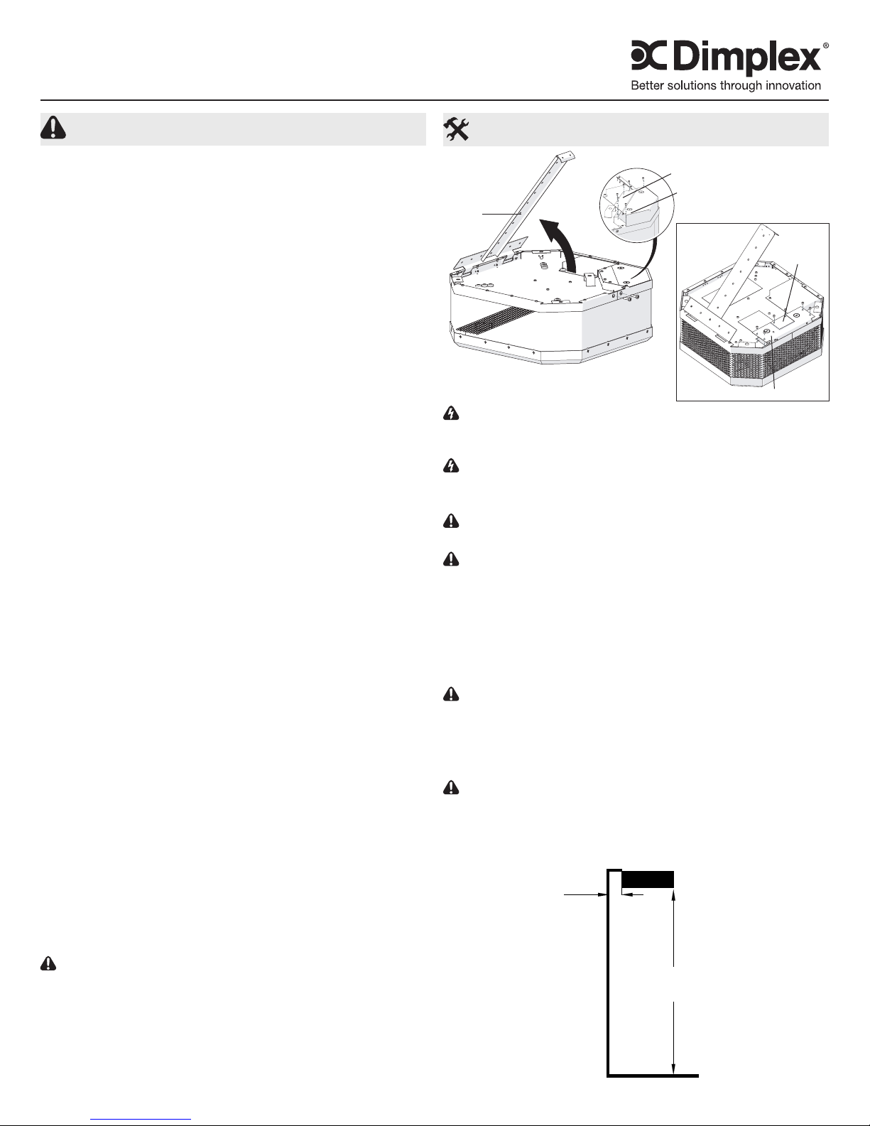
Installation Instructions
Figure 1
7.5 - 10 kW
Mounting
Bracket
WARNING: Wiring procedures and connections should be
in accordance with the National Electric code (NEC) and local
codes.
WARNING: To reduce the risk of re, do not store or use
gasoline or other ammable vapors and liquids in the vicinity
of the heater.
CAUTION: It is recommended that two people install the
unit.
CAUTION: The heater should be mounted for DOWNWARD discharge only.
Surface Mount
1. Unpack the heater from the carton and remove the two
screws securing the bracket to the unit, to remove the
mounting bracket, and remove the terminal box covers.
(Figure 1)
CAUTION: Care should be taken when removing the terminal box cover, as the electrical connections are attached to it.
2. Determine the desired location for the heater and secure
the mounting bracket to the ceiling (hardware not includ-
ed).
CAUTION: The ceiling and mounting hardware must have
adequate strength to support the heater. Attachment to a rm
support is a necessity.
!
NOTE: See Figure 2 for minimum clearances for the unit.
Figure 2
MINIMUM
2-5kW - 10" (250mm)
7.5-10kW - 16" (410mm)
Inspection Cover
Terminal
Box Cover
2 - 5 kW
2-5 kW - 6' (152 cm)
8 ft (244 cm)
7.5-10 kW - 8' (213 cm)
Inspection
Cover
Terminal Box Cover
SAVE THESE INSTRUCTIONS
7213180100R04
Page 2
3. Remove the desired knockout from the terminal box.
!
NOTE: It is only necessary to remove the knockout(s) that
will feed the power supply wiring, keeping in mind the heater
mounting location and supply wire location.
4. Hang the heater from the hooked edge of the mounting
bracket and proceed to the wiring instructions.
Hanging Mount (Threaded Rod)
1. Unpack the heater from the carton, remove the two screws
securing the bracket to the unit and remove the screws
securing the terminal box cover. (Figure 1)
CAUTION: Care should be taken when removing the termi-
nal box cover, as the electrical connections are attached to it.
!
NOTE: See Figure 2 for minimum clearances for the unit.
2. There are four brackets on the top surface of the unit with
1/2 in. (13 mm) holes which can be used to suspend the
unit from an open ceiling using 3/8” (9.5 mm) threaded
rod.
3. Remove the desired knockout from the terminal box.
!
NOTE: It is only necessary to remove the knockout(s) that
will feed the power supply wiring, keeping in mind the heater
mounting location and supply wire location.
Wiring
WARNING: Wiring procedures and connections should be
in accordance with the National Electric Code (NEC) and local
codes.
1. Run supply wiring of proper voltage and wire size to the
location of the terminal box of the heater. (See Table 2)
Supply wiring should be enclosed in 1/2 in. (13 mm) con-
duit.
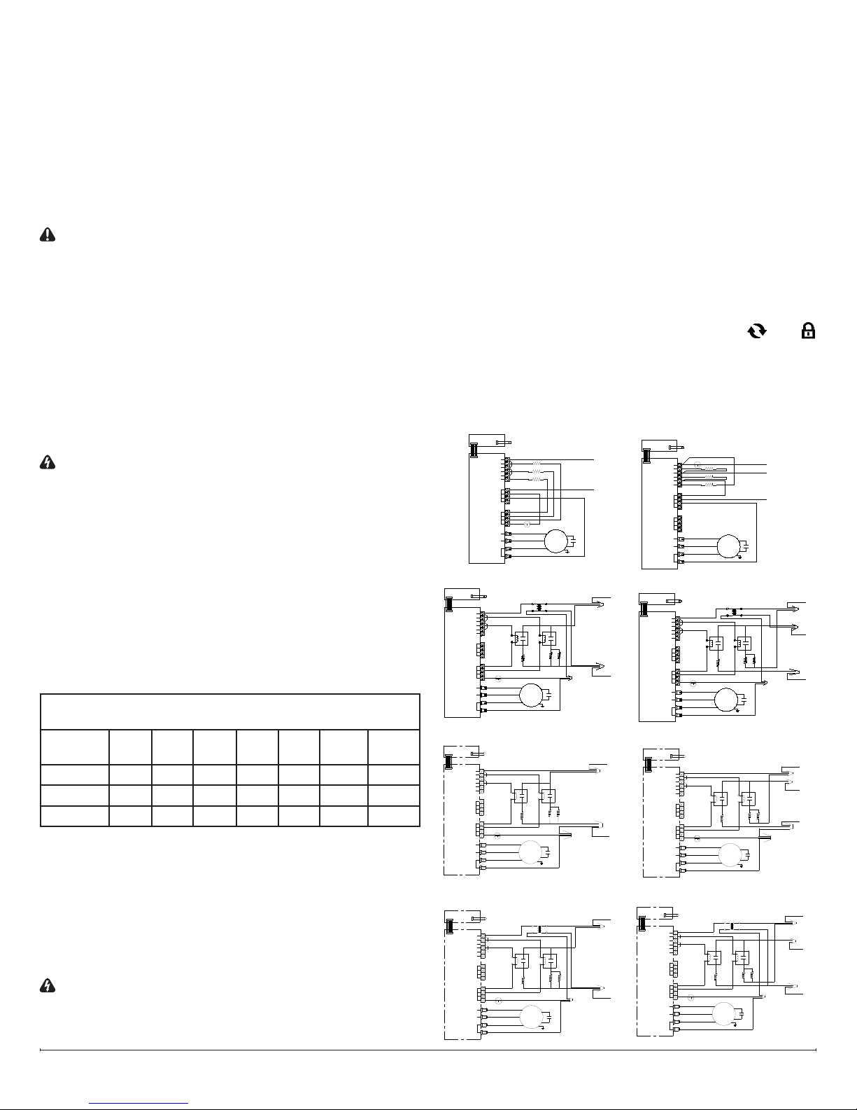
2. Wire all heaters and controls in accordance with the ap-
propriate wiring diagram.
!
NOTE: The wiring diagram for specic unit is located on
top of the heater.
Table 2 - Recommended minimum supply wire sizes are
listed in the table below:
MAXIMUM WATTS PER CIRCUIT USING 75 °C WIRE
(COPPER WIRE)
Rough in
Wire Size
14 1440 2496 2880 3324 4164 5760 7200
12 1920 3328 3840 4432 5552 7680 9600
10 2880 4992 5760 6648 8328 11520 14400
!
NOTE: Supply wire entry is commonly made into one
heater. Though wiring (factory furnished) can be used for connection to adjacent heaters.
3. Wrap the supply ground wire around the green ground
screw and tighten.
4. Do a nal and complete check of all wiring then replace the
terminal box covers being careful not to pinch any wires.
5. The terminal box covers may now be reinstalled.
WARNING: TO PREVENT THE RISK OF FIRE OR IN-
JURY, DO NOT OPERATE THE HEATER UNLESS IT IS
FULLY ASSEMBLED.
120V 208V 240V 277V 347V 480V 600V
!
NOTE: The inspection cover is intended to provide access
for electrical inspections.
6. Swing the heater upwards to secure the opposite side of
the heater to the bracket and secure with previously removed screws.
Initial Set Up
After the unit has been installed, calibration of the unit to the
area will be required. This can be done by closing all doors
and windows to the room and turning the unit ON. When the
unit is initially turned on there is a 28 minute period of calibra-
tion of the unit where the software runs at full power for 20
minutes, then runs for 8 minutes to cool the heater down.
If the unit is relocated or the size of the area that it is installed
in changes, it is recommended that the unit be reset to the factory default to allow the unit to recalibrate.
Factory Default
1. Press and hold the V for 3 seconds. Both the and
icons will begin to ash.
2. Within 5 seconds press ✚, then ✚, then –, then –, then
V, then –.
Sample Wiring Diagrams
240V 2/3/4/5KW 1PH
SENSOR
DISPLAY BOARD
14
13
12
H1
11
10
H2
9
H3
TB1
8
7
6
5
POWER BOARD
TB3
4
3
2
1
TB2
CUTOUT
T1/FAN LOW
T3/FAN HIGH
T2/FAN NEUTRAL
T4/L2
347/600V 3/4/5KW 1PH
SENSOR
DISPLAY BOARD
14
13
12
11
10
9
20A
TB1
CONTACTOR
8
7
6
5
POWER BOARD
TB3
4
3
2
1
TB2
CUTOUT
T1/FAN LOW
T3/FAN HIGH
T2/FAN NEUTRAL
T4/L2
208V/240V 7.5/10KW 1PH
SENSOR
DISPLAY BOARD
14
13
12
11
10
9
30A
TB1
CONTACTOR
8
7
6
5
POWER BOARD
TB3
4
3
2
1
TB2
CUTOUT
T1/FAN LOW
T3/FAN HIGH
T2/FAN NEUTRAL
T4/L2
L1
T1
H1
L1
T1
H1
TRANSFOMER
FAN
MOTOR
FAN
MOTOR
MOTOR
347/600V240V
L1
T1
H2
G
L1
T1
H2
G
480V/600V 7.5/10KW 1PH
SENSOR
DISPLAY BOARD
POWER BOARD
14
13
12
11
10
9
TB1
8
7
6
5
TB3
4
3
2
1
TB2
T1/FAN LOW
T3/FAN HIGH
T2/FAN NEUTRAL
T4/L2
20A
CONTACTOR
CUTOUT
L1
T1
H1
TRANSFOMER
240V
FAN
MOTOR
480V/600V
H2
G
L1
T1
FAN
CONTACTOR
CONTACTOR
CONTACTOR
L1
L2
G
L1
20A
H3
L2
L1
40A
H3
L2
L1
20A
H3
L2
240V 3/4/5KW 3PH
SENSOR
DISPLAY BOARD
CUTOUT
14
13
12
H1
11
10
H2
9
H3
TB1
8
7
6
5
POWER BOARD
TB3
4
3
2
1
TB2
T1/FAN LOW
T3/FAN HIGH
T2/FAN NEUTRAL
T4/L2
600V 3/4/5KW 3PH
SENSOR
DISPLAY BOARD
14
13
12
11
10
9
8
7
6
5
POWER BOARD
208V 7.5/10KW 3PH
DISPLAY BOARD
POWER BOARD
TB1
CONTACTOR
TB3
4
3
2
1
TB2
CUTOUT
T1/FAN LOW
T3/FAN HIGH
T2/FAN NEUTRAL
T4/L2
SENSOR
14
13
12
11
10
9
TB1
CONTACTOR
8
7
6
5
TB3
4
3
2
1
TB2
CUTOUT
T1/FAN LOW
T3/FAN HIGH
T2/FAN NEUTRAL
T4/L2
L1
20A
T1
H1
30A
H1
FAN
MOTOR
TRANSFOMER
240V 347/600V
FAN
MOTOR
T1
FAN
MOTOR
G
L1
T1
H2 H3
G
H2
G
L1L1
T1
L1
L2
L3
20A
CONTACTOR
CONTACTOR
H3
L2
L1
40A
L3
277V/347V/480V/600V 7.5/10KW 3PH
SENSOR
DISPLAY BOARD
POWER BOARD
14
13
12
11
10
9
TB1
8
7
6
5
TB3
4
3
2
1
TB2
T1/FAN LOW
T3/FAN HIGH
T2/FAN NEUTRAL
T4/L2
20A
CONTACTOR
CUTOUT
L1
T1
H1
TRANSFOMER
240V
FAN
MOTOR
277V/347V/480V/600V
L1
CONTACTOR
T1
H2
G
L2
L1
30A
H3
L2
L1
L3
L3
www.dimplex.com2
Page 3

Operation
Figure 3
A - Setting/Temperature Display
B - Comfort Setting Icon
C - Economy Setting Icon
D - Set Back Temperature Setting
E - Synchronized Icon
F - Lock Icon
G - Decrease Button
H - Increase Button
I - Menu Button
icon ashing. After the Set Back Temperature has been set,
the icon will become solid after three seconds and the Set
Back Temperature will be enabled.
To return back to the Comfort Setting press the V button. The
icon will disappear and the icon will appear.
D. Set Back Temperature Setting
The Set Back Temperature Setting is used during periods
when the Economy setting feature is active. This temperature
adjustment can be set by pressing the V followed by the ✚ or
–.
A
D
C
B
F
E
H
G
I
WARNING: This heater is factory prewired for operation
with the built-in thermostat. THIS HEATER IS NOT TO BE
USED WITH A REGULAR WALL THERMOSTAT.
CAUTION: This heater must be properly installed before
it is used.
The CMH is designed with a two stage heating element that
will turn on and off based on the built-in temperature sensor to
maintain a constant room temperature.
!
NOTE: The element retains heat after shutdown, there is
a built in cool down period of 5 minutes before the fan shuts
off completely.
Manual Controls
(See Figure 3 for display reference)
When power is rst supplied to the CMH the Setpoint Tem-
perature will ash in the temperature display area. At any time
either the ✚ or – button can be pressed to have the tempera-
ture setpoint displayed again.
A. Setting/Temperature Display
The CMH is designed to control the temperature of a room
from 41-104°F (5-40 °C). By pressing the ✚ or – will increase
or decrease the desired temperature for the room to be heated
by 0.5° (in either °C or °F).
When adjusting the Setpoint Temperature the display will
switch back to display the ambient temperature after 5 sec-
onds.
!
NOTE: The unit can be set to run continuously as a fan by
setting the temperature at 41 °F (5 °C). At this temperature
the heater will not turn on.
!
NOTE: Pressing the ✚ and – at the same time will toggle
between °C and °F.
B. Comfort Setting
The Comfort Setting icon will be displayed when the heater
is in normal operation based on the Setpoint Temperature for
the room.
!
NOTE: Either the or icon will always be visible, de-
pendent on the setting being used.
C. Economy Setting
The Economy Setting can be used to change the Setpoint
Temperature for a user determined period of time. By pressing
the V the Economy Setting will be enabled - signied by the
E. Synchronized Icon
The CMH features CONNEXTM, a wireless technology that
works with Dimplex single and multi-zone CONNEXTM controllers to provide simple whole home connectivity and comfort.
CONNEXTM controllers are available to control one or multiple
CONNEX
TM
series heaters within a 50’ (15 m) radius. In order
for the controller to have this function the CMH and the controller will need to be synchronized. To do this:
1. On the CMH press and hold the V button for 3 seconds,
both the and icons will begin to ash.
2. Press the – , ✚ and then V, on the CMH.
3. Within 10 seconds press any button once on the
CONNEXTM Controller.
!
NOTE: There is a 3 second delay between pressing the last
button on the controller and the CMH.
!
NOTE: To desynchronize a CMH from the synchronized
CONNEXTM Controller; on either the CMH or the controller:
1. Press and hold the V for 3 seconds.
2. Press the V, ✚ and then –.
Nothing will need to be done to the other component.
Dimplex single and multi-zone CONNEXTM controllers are sold
separately and are available for purchase from your authorized Dimplex dealer.
To nd your local Dimplex dealer, visit www.dimplex.com.
F. Lock Icon
The CMH has a Lock feature to prevent settings from accidentally being changed.
1. Press and hold the V for 3 seconds. Both the and
Icons will begin to ash.
2. To Enable: Within 5 seconds press ✚, then –, then ✚,
then –. The icon will appear
To Disable: Within 5 seconds press –, then ✚, then –,
then ✚. The icon will disappear.
!
NOTE: The CMH can be locked in either the Comfort or
Economy Setting. Ensure that the desired icons are present
when locking is complete.
Boost Function
The CMH is also equipped with a “Boost Function” which allows the user to run the unit at full heat, for a predetermined
amount of time, to quickly heat up a cold room/space. The
Boost can be set for a maximum of 20 minutes, in 5 minute
increments.
To enable Boost:
1. Press and hold ✚ for 5 seconds. The area where the tem-
perature normally displays will begin to toggle between
3
Page 4

the display of “HI” and “20”.
!
NOTE: The “20” indicates the time (in minutes) remaining
in Boost function. The timer is updated as the time counts
down 19, 18, 17, etc.
2. The length of time that Boost is enabled for can be ad-
justed by pressing the ✚ or – buttons. Every time the
✚ or – button is pressed the timer will be adjusted by 5
minutes and will cycle back to 20 minutes.
3. When the timer times out the heater will return to the programmed settings.
!
NOTE: At any time you can hold down the – button for 5
seconds and exit the Boost function.
Replacement Parts
2-5 kW Units (Small)
Cutout ............................... 00009112RP
Fan Blade ..........................5300020200RP
Motor ..............................2000470100RP
Capacitor ...........................3200070100RP
Housing Cover ................. CMH-COVER-S-W-RP
ConnexTM Components
Display Board ................CMH-DISPLAYPCB-RP
Power Board ................. CMH-POWERPCB-RP
Temperature Sensor .................2500670100RP
Item #
CMH35A34CX
CMH02A31CX Not required DMP-26B-RP
CMH35A51CX 110XE-
CMH35A84CX DMP-26J-RP DMP-26K-RP 2100120500RP
Contactor
(2 per Unit)
N/A
BA00100000-
01RP
(Top Element)
DMP-26B-RP DMP-26C-RP
DMP-26F-RP DMP-26G-RP 2100120200RP
7.5 - 10 kW Units (Large)
Cutout ...............................00009112RP
Fan Blade ..........................5300020200RP
Motor ..............................2000470100RP
Capacitor ...........................3200070100RP
Contactor (2 per Unit) .................2400220100RP
Housing Cover ................... CMH-COVER-L-RP
ConnexTM Components
Display Board ............... CMH-DISPLAYPCB-RP
Power Board .................CMH-POWERPCB-RP
Temperature Sensor .................2500780100RP
Item #
CMH810A21CX DMP-24-01RP DMP-24-02-RP
CMH08A23CX DMP-24-02-RP
CMH10A23CX DMP-24-01-RP DMP-24-02-RP
CMH810A31CX DMP-24-03-RP DMP-24-04-RP
CMH810A41CX DMP-24-05-RP DMP-24-07-RP
CMH810A51CX DMP-24-08-RP DMP-24-09-RP
CMH810A71CX DMP-24-10-RP DMP-24-11-RP
CMH08A73CX DMP-24-10-RP
CMH10A73CX DMP-24-10-RP DMP-24-11-RP
CMH810A81CX DMP-24-12-RP DMP-24-14-RP
CMH08A83CX DMP-24-12-RP
CMH10A83CX DMP-24-12-RP DMP-24-14-RP
P/N NO.
(Top Element)
Elements
P/N NO.
Elements
P/N NO.
(2 Bottom
Elements)
P/N NO.
(2 Bottom
Elements)
Transformer
N/A
Transformer
N/A
2100240100RP
2100240200RP
Maintenance
WARNING: Always disconnect power at the circuit breaker
to the unit prior to performing any maintenance or service
operation.
CAUTION: Allow adequate time for the element and body
casing to cool before attempting to work on the heater.
It is suggested that the heater be inspected regularly, for cleanliness of the fan intake and exhaust grilles, to ensure optimal
performance is maintained. The grilles can be cleaned either
by vacuuming off all dust and dirt or, washing the lter in warm,
soapy water and allowing to dry thoroughly before reinstalling.
Once cleaning is complete replace the grille and restore pow-
er.
WARNING: TO PREVENT THE RISK OF FIRE OR IN-
JURY, DO NOT OPERATE THE HEATER UNLESS IT IS
FULLY ASSEMBLED.
At least at yearly intervals the wire connection condition should
be inspected to ensure full electrical continuity and optimal
performance is maintained.
WARNING: The user can perform cleaning ONLY. All other
servicing should be performed by qualied service person-
nel.
Warranty
The Manufacturer warrants the CMH series ceiling heaters and components of the enclosed product against any defect in material or
workmanship for a period of one year from the date of purchase,
with the exception of the elements which are warranted to be free
from defect in material and workmanship for ten years. In full satisfaction of any claims under this Warranty the Manufacturer will repair
or replace without charge, in its factory or in the eld as it alone may
decide, any parts which in its opinion are defective.
The Manufacturer shall not be responsible for any transportation or
shipping costs in relation to such repair or replacement except as
specically assumed by it. Misuse of this product or repairs by persons other than the Manufacturer’s authorized personnel without the
Manufacturer’s written approval, will void this Warranty.
This Warranty is in lieu of all other warranties or conditions whether
express or implied including but not limited to those of merchantability or tness for purpose and shall constitute the sole remedy of
the Purchaser and the sole liability of the Manufacturer in respect of
the sale of the product, whether in the nature of breach or breach of
fundamental term, or of negligence or otherwise.
The Manufacturer shall not be liable for any special, indirect or consequential damages or for any damages resulting from removal or
replacement of a heater subject to warranty claim without the Manufacturer’s authorization.
This Warranty is transferable by the original consumer purchaser
of the product. Any claims under this Warranty must be submitted
in writing to the Service Manager, Dimplex North America Ltd., 1367
Industrial Rd., Cambridge, Ontario N1R 7G8, Canada.
1367 Industrial Road Cambridge ON Canada N1R 7G8
1-888-346-7539 www.dimplex.com
In keeping with our policy of continuous product improvement, we reserve the right to make changes without notice.
© 2014 Dimplex North America Limited
 Loading...