

Dimplex CMH35A34, CMH810A21, CMH35A51, CMH35A84, CMH08A23 Installation Instructions Manual
...Page 1

Ceiling Heater
CMH Series
IMPORTANT INSTRUCTIONS
When using electrical appliances, basic precautions should
always be followed to reduce the risk of re, electric shock
and injury to person, including the following:
1. Read all instructions before using this heater.
2. The heater is hot when in use. To avoid burns, do not let
bare skin touch hot surfaces. Keep combustible materials, such as furniture, pillows, bedding, papers, clothes,
and curtains at least a 3.3 ft (1 m) from the front of the
heater and keep them away from the sides and rear.
3. Wiring procedures and connections should be in accordance with the National Electric Code (NEC & CEC) and
local codes.
4. Extreme caution is necessary when any heater is used
by or near children or invalids and whenever the unit is
left operating and unattended.
5. Do not operate any heater after it malfunctions. Disconnect power at service panel and have heater inspected
by a certied electrician before reusing.
6. To disconnect heater, turn off power to heater circuit at
main disconnect panel.
7. Do not use outdoors.
8. Use this heater only as described in this manual. Any
other use not recommended by the manufacturer may
cause re, electric shock, or injury to persons.
9. A heater has hot and arcing or sparking parts inside. Do
not use it in areas where gasoline, paint or ammable
liquids are used or stored.
10. This heater is hot when in use. To avoid burns, do not let
bare skin touch hot surfaces. Keep combustible materials
such as: furniture, pillows, bedding, papers, clothes and
curtains away from heater.
11. Do not insert or allow foreign objects to enter any ventilation or exhaust opening as this may cause an electric
shock or re, or damage the heater.
12. To prevent a possible re, do not block air intake or ex-
haust in any manner.
SAVE THESE INSTRUCTIONS
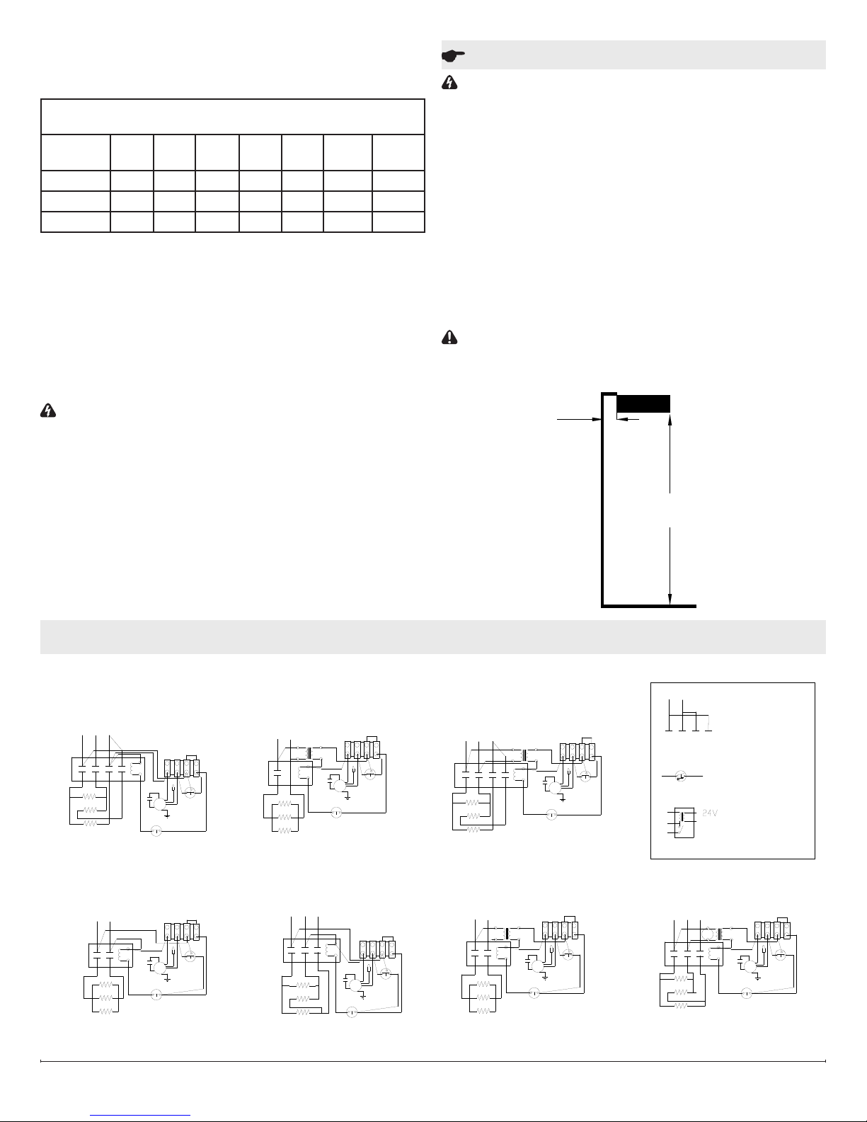
Figure 1
7.5 - 10 kW
Mounting
Bracket
Terminal
Box Cover
2 - 5 kW
Terminal Box Cover
Installation Instructions
WARNING: Wiring procedures and connections should
be in accordance with the National Electric code (NEC) and
local codes.
WARNING: To reduce the risk of re, do not store or use
gasoline or other ammable vapors and liquids in the vicinity
of the heater.
CAUTION: It is recommended that two people install the
unit.
CAUTION: The heater should be mounted for DOWN-
WARD discharge only.
Surface Mount
1. Unpack the heater from the carton and remove the two
screws securing the bracket to the unit, to remove the
mounting bracket, and remove the terminal box covers.
(Figure 1)
2. Determine the desired location for the heater and secure the mounting bracket to the ceiling (hardware not
included).
CAUTION: The ceiling and mounting hardware must have
adqueate strength to support the heater. Attachment to a rm
support is a necessity.
!
NOTE: See Figure 2 for minimum clearances for the unit.
3. Remove the desired knockout from the terminal box.
!
NOTE: It is only necessary to remove the knockout(s)
that will feed the power supply wiring, keeping in mind the
heater mounting location and supply wire location.
4. Hang the heater from the hooked edge of the mounting
bracket and proceed to the wiring instructions.
Hanging Mount (Threaded Rod)
1. Unpack the heater from the carton and remove the two
screws securing the bracket to the unit, to remove the
mounting bracket and terminal box cover. (Figure 1)
!
NOTE: See Figure 2 for minimum clearances for the unit.
2. There are four brackets on the top surface of the unit
with 1/2 in. (13 mm) threaded holes which can be used to
suspend the unit from an open ceiling using 3/8 in. (9.5
mm)
Wiring
WARNING: Wiring procedures and connections should
be in accordance with the National Electric Code (NEC) and
local codes.
1. Run branch circuit wiring of proper voltage and wire
size to the location of the terminal box of the heater.
(See Table 2 for line amperes) Control wiring should be
enclosed in 1/2 in. (13 mm) conduit.
2. Wire all heaters and controls in accordance with the ap-
propriate wiring diagram.
!
NOTE: Sample wiring diagrams are located on the last
page, wiring diagram for specic unit is located on top of the
7213190100R03
Page 2
heater.
Recommended minimum supply wire sizes are listed in the
table below:
TABLE 2: MAXIMUM WATTS PER CIRCUIT USING 75 °C WIRE
(COPPER WIRE)
Rough in
Wire Size
120V 208V 240V 277V 347V 480V 600V
14 1440 2496 2880 3324 4164 5760 7200
12 1920 3328 3840 4432 5552 7680 9600
10 2880 4992 5760 6648 8328 11520 14400
!
NOTE: Supply wire entry is commonly made into one
heater. Though wiring (factory furnished) can be used for
connection to adjacent heaters.
3. Wrap the supply ground wire around the green ground
screw & tighten.
4. Do a nal and complete check of all wiring then replace
the terminal box covers being careful not to pinch any
wires.
5. The terminal box cover may now be reinstalled.
WARNING: TO PREVENT THE RISK OF FIRE OR IN-
JURY, DO NOT OPERATE THE HEATER UNLESS IT IS
FULLY ASSEMBLED.
!
NOTE: The smaller terminal box cover is intended to provide access for electrical inspections.
6. Swing the heater upwards to secure the opposite side
of the heater to the bracket and secure with previously
removed screws.
Operation
WARNING: This heater must be properly installed before
it is used.
1. Prior to energization remove all construction dirt (plaster,
sawdust, etc.) from interior and exterior of heater.
2. This unit is controllable from a line voltage wall thermostat or a low voltage thermostat through a relay, refer to
the wiring diagram.
Dimplex ceiling heaters are designed and tested for safe and
trouble-free operation. All Dimplex ceiling heaters are protected against overheating by a built-in thermal cutout. Free
airow throughout the heater is extremely important for the
most efcient operation of the heater. Restricted airow may
cause the thermal overload protector to cycle the heater “ON
and OFF”. A cycling heater will not supply sufcient heat to
the room.
CAUTION: Avoid direct contact of paper, fabric, or furni-
ture with heater.
Figure 2
MINIMUM
2-5kW - 10" (250mm)
7.5-10kW - 16" (410mm)
2-5 kW - 6' (152 cm)
8 ft. (244 cm)
7.5-10 kW - 8' (213 cm)
Wiring
240V 3/4/5KW 1/3PH
L3L2L1
CONTACTOR
L1
L2
T1
T4L4T3L3T2
H1
H2
H3
208V/240V
7.5kW/10kW 1PH
L1
L2
L1
CONTACTOR
L2
T1
T2
H1
H2
H3
TERMINAL BLOCK
M
FAN
MOTOR
CUTOUT
TERMINAL BLOCK
M
FAN
MOTOR
CUTOUT
G
1
G
2
FAN DELAY
2
3
2
1
FAN DELAY
347V 3/4/5KW 1PH
FAN
MOTOR
CUTOUT
TERMINAL BLOCK
3
1
2
2
1
FAN DELAY
M
G
4
3
L2
L1
347VL1240V
4321
CONTACTOR
31
T1
H1
H2
H3
208V/240V
7.5kW/10kW 3PH
L3L2L1
FAN
MOTOR
CUTOUT
M
TERMINAL BLOCK
4
321
2
31
FAN DELAY
G
4
3
CONTACTOR
L2T1L1
L3
T2
T3
H1
H2
H3
600V 3/4/5KW 1/3PH
L1
L3
L2
CONTACTOR
L1
T1
600V 240V
L4
L2
L3
T4
T3
T2
H1
H1
H2
H2
H3
H3
FAN
MOTOR
CUTOUT
277V/347V/480V/600V
7.5kW/10kW 1PH
240V
MOTOR
TERMINAL BLOCK
1
M
FAN
G
CUTOUT
CONTACTOR
L2
L1
L1
L2
T1
T2
H1
H2
H3
TERMINAL BLOCK
31
2
2
1
FAN DELAY
M
G
4
3
2
2
3
1
FAN DELAY
4
3
CONTACTOR
L2L1L1
REMOVE JUMPER
L4
L3L2
BETWEEN
1PH OPTION
3
LINE STAT
TERMINAL BLOCK
3,4,
4
CONNECT
REMOTE STAT TO
3, 4 OR RELAY TO
1
3
4
RELAY
1,3,4
480V/600V
7.5kW/10kW 3PH
L1
L3
L2
240V
50
L3
L1
L2
T2
T1 T3
H1
H1
H2
H2
H3
H3
FAN
MOTOR
CUTOUT
TERMINAL BLOCK
31
2
2
1
FAN DELAY
M
G
4
3
www.dimplex.com2
Page 3

Maintenance
WARNING: Always disconnect power at the circuit
breaker to the unit prior to performing any maintenance or
service operation.
CAUTION: Allow adequate time for the element and body
casing to cool before attempting to work on the heater.
It is suggested that the heater be inspected regularly, for
cleanliness of the fan intake and exhaust grilles, to ensure optimal performance is maintained. The grilles can be
cleaned either by vacuuming off all dust and dirt or, washing
the lter in warm, soapy water and allowing to dry thoroughly
before reinstalling.
Once cleaning is complete replace the grille and and restore
power.
WARNING: TO PREVENT THE RISK OF FIRE OR IN-
JURY, DO NOT OPERATE THE HEATER UNLESS IT IS
FULLY ASSEMBLED.
At least at yearly intervals the wire connection condition
should be inspected to ensure full electrical continuity and
optimal performance is maintained.
WARNING: The user can perform cleaning ONLY. All
other servicing should be performed by qualied service
personnel.
Warranty
The Manufacturer warrants the CMH series ceiling heaters and
components of the enclosed product against any defect in material
or workmanship for a period of one year from the date of purchase,
with the exception of the elements which are warranted to be free
from defect in material and workmanship for ten years. In full satisfaction of any claims under this Warranty the Manufacturer will re-
pair or replace without charge, in its factory or in the eld as it alone
may decide, any parts which in its opinion are defective.
The Manufacturer shall not be responsible for any transportation
or shipping costs in relation to such repair or replacement except
as specically assumed by it. Misuse of this product or repairs by
persons other than the Manufacturer’s authorized personnel without
the Manufacturer’s written approval, will void this Warranty.
This Warranty is in lieu of all other warranties or conditions whether
express or implied including but not limited to those of merchant-
ability or tness for purpose and shall constitute the sole remedy of
the Purchaser and the sole liability of the Manufacturer in respect of
the sale of the product, whether in the nature of breach or breach of
fundamental term, or of negligence or otherwise.
The Manufacturer shall not be liable for any special, indirect or consequential damages or for any damages resulting from removal or
replacement of a heater subject to warranty claim without the Manufacturer’s authorization.
This Warranty is transferable by the original consumer purchaser
of the product. Any claims under this Warranty must be submitted
in writing to the Service Manager, Dimplex North America Ltd., 1367
Industrial Rd., Cambridge, Ontario N1R 7G8, Canada.
Replacement Parts
2-5 kW Units (Small)
Fan Delay ............................00033001RP
Cutout ...............................00009112RP
Fan Blade ..........................5300020200RP
Motor ..............................2000470100RP
Capacitor ...........................3200070100RP
Terminal Block ...............110UDBA00100000-01RP
Housing Cover ....................CMH-COVER-S-RP
Elements
Item # Contactor
CMH35A34 2400170900RP DMP-26B-RP DMP-26C-RP N/A
CMH35A51
CMH35A84 2400170900RP DMP-26J-RP DMP-26K-RP 2100120500RP
110XE-
BA00100000-
01RP
P/N NO.
(Top Element)
DMP-26F-RP DMP-26G-RP 2100120200RP
7.5 - 10 kW Units (Large)
Fan Delay ............................00033001RP
Cutout ...............................00009112RP
Fan Blade ..........................5300020200RP
Motor ..............................2000470100RP
Capacitor ...........................3200070100RP
Terminal Block .......................4000170100RP
Housing Cover ................... CMH-COVER-L-RP
Item # Contactor
CMH810A21 2400220200RP DMP-24-01RP DMP-24-02-RP
CMH08A23
CMH10A23 DMP-24-01-RP DMP-24-02-RP
CMH810A31
CMH810A41 DMP-24-05-RP DMP-24-07-RP
CMH810A51 DMP-24-08-RP DMP-24-09-RP
CMH810A71 DMP-24-10-RP DMP-24-11-RP
CMH08A73
CMH10A73 DMP-24-10-RP DMP-24-11-RP
CMH810A81 2400220200RP DMP-24-12-RP DMP-24-14-RP
CMH08A83
CMH10A83 DMP-24-12-RP DMP-24-14-RP
2400160300RP
2400220200RP
2400160300RP
2400160300RP
P/N NO.
(Top Element)
DMP-24-02-RP
DMP-24-03-RP DMP-24-04-RP
DMP-24-10-RP
DMP-24-12-RP
(2 Bottom
Elements)
Elements
P/N NO.
P/N NO.
(2 Bottom
Elements)
Transformer
Transformer
N/A
2100240100RP
2100240200RP
1367 Industrial Road Cambridge ON Canada N1R 7G8
1-888-346-7539 www.dimplex.com
In keeping with our policy of continuous product improvement, we reserve the right to make changes without notice.
© 2014 Dimplex North America Limited
 Loading...