

Page 1
Kickspace Heater
22”
9 1/2”
3 1/2”
3” MAX.
22 3/8”
10” MIN.
SERVICE
WIRES
KNOCKOUT
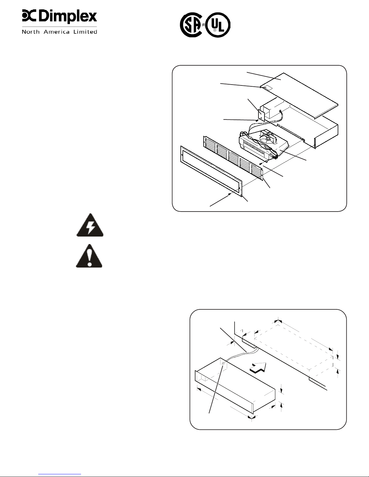
Kickspace Heater
MODEL 610048000
TOP LABEL
HEATER COVER
JUNCTION BOX COVER
SCREW “C”
HEATER
ELEMENT
SCREW “B”
SCREW “A”
GRILLE
TRIM FRAME
Fig. 1
1-888-346-7539
INSTALLATION INSTRUCTIONS
Notes
Care must be taken to prevent undue strain on all
wiring or heating element assembly, when removing
and re-assembling heating element assembly.
For eld rewiring to 120V all leads must be secured
under wire clamps.
Air and grille temperatures conform to CSA & UL
regulations but may discolour certain materials,
particularly those materials incorporating clear vinyl.
Materials should be checked prior to installation to
determine if discolouration or distortion would occur
in the vicinity of 60°C (140° F)
General
To prepare the unit for installation, rst check that
heater nameplate voltage is the same as electrical
service.
WARNING - Hazard of severe shock
MODEL CKHA/RKHA
HEATER COVER
TOP LABEL
JUNCTION BOX COVER
SCREW ‘C’
SCREW ‘A’
HEATER
ELEMENT
SCREW ‘B’
GRILLE
TRIM FRAME
Fig. 1
CAUTION - Disconnect all power coming to heater at main
service panel before wiring or servicing.
Kickspace Installation
NOTE - Unit should be installed so that it is not directly under sink or other frequently used work area as air temperature
may be uncomfortably warm. Also, if carpeting is on oor, mount unit so bottom of grille is level or above the top of the
carpet pile.
1. Measure area of intended use. If there is not
sufcient room for the grille frame, the frame may
be removed by removing grille frame from heater
(screw “A”), remove frame and re-insert grille.
2. Cut 22 3/8” x 3 5/8” opening (Fig.2). Keep
clearance area free of obstructions.
3. Bring in service cable to left or rear of 10” minimum
area as shown in Fig.2.
4. Remove heater cover and appropriate knockout.
Attach service cable to unit with approved
connector and connect colour to colour in outlet
box. To change wattage or voltage connections,
see Fig.4.
5. Replace cover, slide unit into opening, and secure
each side (Fig.1).
NOTE - Make sure unit is installed right side up.
Refer to “TOP” label.
6. For inspection of eld wiring, see instruction under “Electrical Inspection”.
Fig. 2
7200960100R05
Page 2
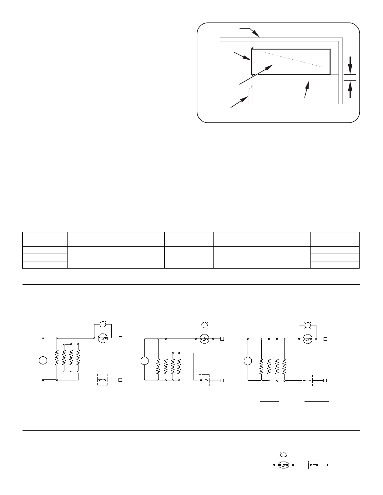
Soft or Stair Riser Installation
CEILING
HEATER
GRILLE
CABINET DOOR
PARTITION OR
ADDED SUPPORT
3/4”
MIN
CATALOG NO. MOTOR FAN BLADE ELEMENT
CUT OUT
(MANUAL)
CUT OUT
(AUTOMATIC)
GRILLE KIT
CKHA20D31 CKHABG
CKHA20D31W CKHAWG
RKHA20D31W 2000280400RP 5300210100RP 2203260100RP 03005035RP 211A619RP CKHAWG
REPLACEMENT PART
1. Cut opening as for kickspace installation (22 3/8” x
3 5/8”). Allow 3/4” clearance above cabinet doors.
Add supports for unit (Fig.3).
2. Proceed as for kickspace installation. After
securing unit in opening, install combination of
frame and grille (g.1).
CAUTION - Disconnect main to de-energize receptacle
before servicing or for electrical inspection.
SERVICING - Remove grille and frame by removing
screws “A”. Remove two screws “B”, and slide out heating assembly. When re-assembling, reverse the
procedure above.
Cleaning
With grille in place - Use vacuum cleaner hose to suck out lint and dirt around grille. Reverse hose on vacuum to
use as a blower to move dust out of enclosure. Reverse hose back to suck out dirt at front area of heater.
With grille removed - Remove two screws “B” at bottom front of heating element assembly. Pull gently to remove
it from enclosure. Swing assembly out. Vacuum inside of enclosure and around heating element assembly.
Reverse procedure above to re-assemble unit.
Thermostat Adjustment (CKHATD13 / CKHATD23)
Adjust thermostat with screwdriver.
FACTORY CONNECTION
208/240 VOLT 675/900 WATTS
3.2 A / 3.7A
FACTORY CONNECTION
208/240 VOLT 1350/1800 WATTS
6.5 A / 7.5 A
FACTORY CONNECTION
120 VOLT
Fig. 3
Fig. 4
FAN
M
IMPORTANT: RETIGHTEN ALL LEADS WITH CABLE CLAMP
AFTER RECONNECTING UNINSULATED ENDS OF
UNUSED LEADS WITH WIRE NUTS
FAN
MM
FAN
SAFETY SWITCH SAFETY SWITCHSAFETY SWITCH
RATING CONNECT
450W/ 3.75A 7-8 (AS SHOWN)
900W/ 7.5A 7-8, 1-2
1350W/ 11.2A 7-8, 1-2, 3-4
1800W/ 15A 7-8, 1-2, 3-4, 5-6
NOTE: If installing unit with factory thermostat, see
supplemental wiring diagram, Fig. 4a.
THERMOSTAT
Fig. 4a
 Loading...