

Page 1
BLOWER ASSEMBLY
CABINET
SCREW "A"
SLOT
FILTER
Electric Cabinet Blower Heater
CH Series
IMPORTANT INSTRUCTIONS
When using electrical appliances, basic precautions should
always be followed to reduce the risk of re, electric shock
and injury to person, including the following:
Read all instructions before using this heater.1.
A heater has hot and arcing or sparking parts inside. Do 2.
not use it in areas where gasoline, paint or ammable
liquids are used or stored.
This heater is hot when in use. To avoid burns, do not let 3.
bare skin touch hot surfaces. If provided, use handles
when moving this heater. Keep combustible materials
such as: furniture, pillows, bedding, papers, clothes and
curtains away from heater.
To prevent a possible re, do not block air intakes or 4.
exhaust in any manner. Do not use on soft surfaces like
a bed where openings may become blocked.
Do not insert or allow foreign objects to enter any venti-5.
lation or exhaust opening as this may cause an electric
shock or re, or damage the heater.
SAVE THESE INSTRUCTIONS
Installation Instructions
Designed for high capacity, forced-air applications in
commercial, industrial or institutional buildings. Installs easily
on oors, walls or ceilings, surface or recess mount.
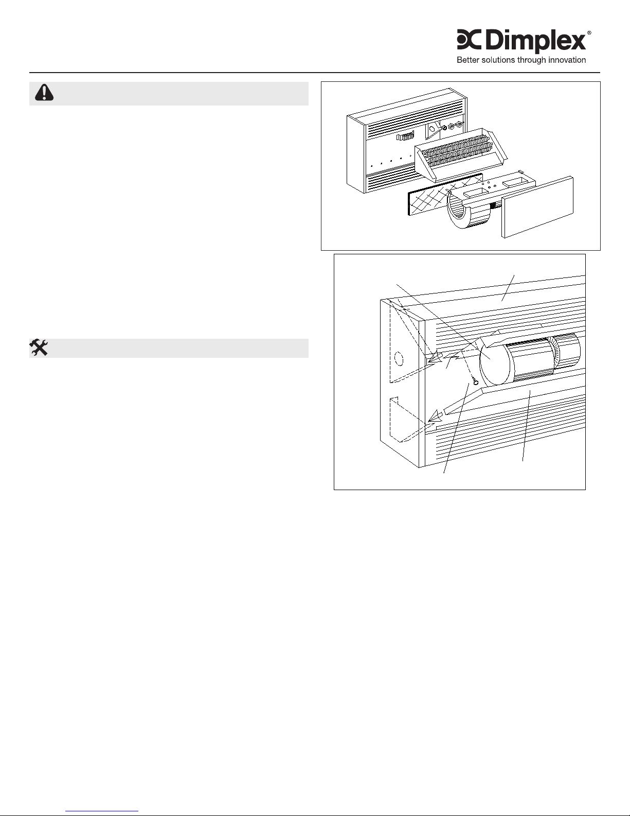
An exploded view of the major components of the CH
Cabinet Heater is shown in Figure 1. The heater is
completely assembled when shipped and must be partially
dismantled for installation.
!
NOTE: This heater is shipped with the outlets in
the front/front (D) conguration, see Figure 7. If another
conguration is required it will be necessary to rearrange the
outlets (See notation REMOVING FRONT PANEL).
REMOVING FRONT PANEL
Remove the cover screws located at top of panel. After
panel is swung open, pull the spring-loaded hinge (located
at one end of panel) towards the centre of the panel. Units
are shipped with doors for upow application. If unit is to
be installed as downow, the panel can be removed and
installed in reverse position. Before mounting the heater
determine the inlet/outlet panel arrangement. Remove the
screws holding the panel(s) in place at the back and at the
front. Reverse the panel(s) and secure back in place.
FASTENING TO WALL
For oor mounted units it is necessary to use only the holes
marked “A” in Figure 3 in order to secure unit to the wall. The
Motor and Blower Assembly need not be removed. The lter
may be removed to assist in installation.
For wall-mounted units, in order to ensure adequate support,
a greater number of mounting holes may be used. To gain
access to them the Motor and Blower Assembly the Filter
must rst be removed. Remove screws at each end of the
Assembly as shown in Figure 2, then pull out Assembly. Be
sure to disconnect plug at the Blower deck before removing
the Assembly. Slide out Filter as shown. The unit is now
ready for securing to the wall.
With ceiling mounted units, use the four (4) 9/16” (14.29 mm)
Figure 1
Filter
Figure 2
diameter knockouts provided on back of unit, use the same
procedure as in the wall-mounted units. Please make sure
that installation is strong enough to support the weight of the
heater.
SEMI/FULL-RECESSED APPLICATIONS
For either semi- or full-recessed applications care must be
taken to provide the proper size of opening in the wall or
ceiling. See Figure 4 for dimensioning details. On the length
and width dimensions, 1/4” (6.35 mm) must be allowed to
insert the trim frame. In a semi-recessed application the unit
can be recessed to any depth except when the inlet and/
or discharge (outlet) are on the top or bottom of the heater
as opposed to the front. Please see Figure 5 for a typical
installation.
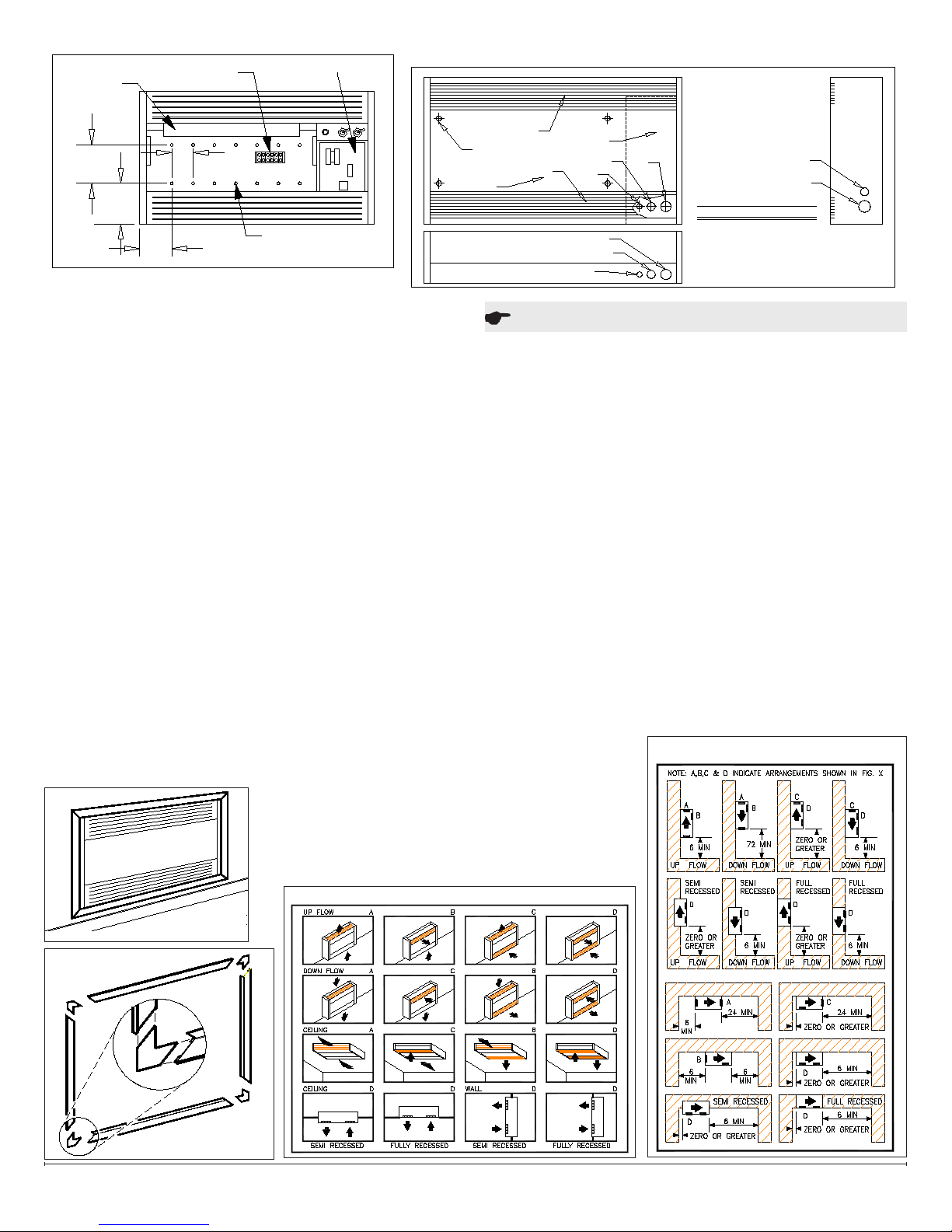
ACCESSORY TRIM FRAME ASSEMBLY
Refer to Figure 6 for assembly. Assemble heater frame on
a at surface. Insert “L” shaped splices into each corner
as shown. Use a carpenter’s square to be sure of exact 90
degree angle at corners. Square up one corner at a time,
then centre punch one at a time to crimp down inside ange
onto “L” shaped splice. Trim frame can be secured to wall
with screws (not provided), cement or adhesive.
Cabinet
Heater
Section
Blower
Assembly
Front
Panel
7203510000R03
Page 2
.562 DIA. KNOCKOUTS
FOR CEILING MOUNT
(SEE NOTE BELOW)
FRONT PANEL
"A"
11.375 DIA.
"E"
"C"
1.375 - 2.000 DIA.
KNOCKOUT SCHEDULE
.875 DIA.
1.750 - 2.000 DIA.
1.750 DIA.
CEILING MOUNTING HOLES ARE
OF HEATER.
SHOWN AS VIEWED FROM FRONT
"B"
INLET
"C"
"A"
"C"
"D"
"B"
ITEM
"A"
"B"
CONTROL SECTION
OUTLET
NOTE:
SIZE (INCHES)
1
2
2
QTY.
2
"D"
"E"
Figure 3
5.875
(149mm)
4.000
(102mm)
7.750
(198mm)
8.000
(203mm)
HEATER
TERMINAL BLOCK
CONTROL PANEL
MOUNTING HOLES
4" (102mm) CENTRES
SECTION
A A
Figure 4
MOUNTING CLEARANCES
In order for this heater to operate properly the clearances
shown in Figure 8 will have to be maintained. Failing to
do so may result in a poor performance from the heater.
Dimensions are shown in inches (millimetres).
DUCT COLLAR MOUNTING
An 18” (457 mm) section of duct work with 90 degrees bends
may be added to the inlet and outlet of the heater with 8”
(203 mm) clearance to combustible surfaces. Inlet and outlet
grilles placed on the end of the must have a minium of 65%
open area. Refer to Figure 9 for cross-sectional dimensions
of duct. Duct collar inlet/outlets can be as per Figure 7.
Secure the duct to the anges provided.
!
NOTE: External static pressure exceeding 0.15”wg is not
recommended.
WIRING INFORMATION
For service entrance refer to Figure 04 for knockout sizes 1.
available and their locations.
!
NOTE: For upow application, control section and knock-
outs are located on lower right side of unit and for downow
application they will be on upper left hand side of unit.
All external wiring to the heater shall be in accordance 2.
to the Local and National Building codes. It is
recommended that only qualied electrical personnel
shall perform any service on this unit.
Figure 5
Refer to data plate and 3.
wiring diagram for correct
voltage and amperage
rating. These must be
considered in the size of
eld wiring.
Figure 7
Operation
The CH Cabinet Heater is available with a choice of control
options to provide exibly of operation in various applications.
The type of control option is reected in the Catalogue
Number as the eighth digit. Please check one of the following
options to ensure that is what has been ordered or required.
-3: The unit is automatically controlled by it’s own built-in
thermostat with a range of 45 degrees F (7 C) to 90 degrees
F (32 C). In addition to the toggle switch (“Heat & Fan”,
“OFF” and “Fan Only”) this option has a two position toggle
switch for High/Low Heat Selection and High/Low Blower
Speed. HIGH and LOW Heat give 100% for HIGH and
approximately 50% Low heat. Correspondingly the blower
speeds are approximately 1050 and 800 R.P.M. The Fan
Delay is effective only on the “OFF” cycle, as the fan comes
on at the same time the heat comes on, during the “Heat &
Fan” cycle.
-T: This option incorporates a two position toggle switch as
in option-3 above and functions the same way. In addition
a low voltage control relay complete with an integral
transformer is provided for connection to a remote 24 volt
thermostat. The fan delay works the same as in “-3” above
also.
-R: This option also
uses the two position
toggle switch as in
the above options.
Provision is provided
for a line voltage
thermostat. The fan
delay works the same
as in “-3” above.
Figure 8
Figure 6
www.dimplex.com2
Page 3

Maintenance
CONTROL SECTION
FRONT PANEL
OUTLET
INLET
NOTE:
ALTERNATE LOCATION OF DUCT
COLLAR WHEN LOCATED AT FRONT
NOTE:
ALTERNATE LOCATION
OF DUCT COLLAR WHEN
LOCATED AT FRONT
CABINET SIZE
32" (813)
45" (1143)
65" (1651)
78" (1982)
DUCT OPENING
4" (102) x 15" (381)
4" (102) x 28" (711)
4" (102) X 49" (1245)
4" (102) X 61 1/4" (1156)
AREA
.41 (.039)
.78 (.072)
1.37 (.127)
1.70 (.158)
SQ. FT. (METER)
If motors or blowers need servicing, or oiling they can 1.
easily be removed removing screws as illustrated in
Figure 2. The complete assembly then slides out, after
electrical plug connector is unplugged.
If heat sections need servicing, they can easily be 2.
removed by removing screws (“A”) in Figure 2. The
complete heat section assembly then slides out, after all
wires into the terminal block are removed. Care must be
taken to assure that all wires are replaced in the correct
terminal block as per wire numbering or coding. The limit
control and elements can be readily serviced when the
heat section is removed.
All controls are readily accessible through the inner 3.
control door. All controls can be serviced through this
door.
Filter is accessible after the front panel is opened. Slide 4.
lter out and clean or replace a minimum of twice per
heating season. Optional permanent type lter can be
cleaned with water and detergent or any available lter
cleaning solution.
Figure 9
Warranty
The Manufacturer warrants the heater and components of the enclosed product
against any defect in material or workmanship for a period of one year from
the date of purchase. In full satisfaction of any claims under this Warranty the
Manufacturer will repair or replace without charge, in its factory or in the eld as it
alone may decide, any parts which in its opinion are defective.
The Manufacturer shall not be responsible for any transportation or shipping
costs in relation to such repair or replacement except as specically assumed
by it. Misuse of this product or repairs by persons other than the Manufacturer’s
authorized personnel without the Manufacturer’s written approval, will void this
Warranty.
This Warranty is in lieu of all other warranties or conditions whether expressed or
implied including but not limited to those of merchantability or tness for purpose
and shall constitute the sole remedy of the Purchaser and the sole liability of the
Manufacturer in respect of the sale of the product, whether in the nature of breach
or breach of fundamental term, or of negligence or otherwise.
The Manufacturer shall not be liable for any special, indirect or consequential
damages or for any damages resulting from removal or replacement of the heater
subject to warranty claim without the Manufacturer’s authorization.
This Warranty is transferable by the original consumer purchaser of the product.
Any claims under this Warranty must be submitted in writing to the Service
Manager, Dimplex North America Ltd., 1367 Industrial Rd., Cambridge, Ontario
N1R 7G8, Canada.
Replacement Parts
Part No. Part No.
Motor 1/10HP 208/240V 1PH 08071101RP
1/20HP 208/240V 1PH 02024293RP
1/30HP 208/240V 1PH 02024101RP
1/20HP 208V 1PH 02024288RP
1/20HP 240V 1PH 02024290RP
1/30HP 277V 1PH 02024102RP
Capacitor 02007005RP
Element 208V 1000w 02030057RP 2000w 02030054RP
240V 1000w 02030058RP 2000w 02030055RP
277V 1000w 02030059RP 2000w 02030056RP
347V 1000w 02050036RP 2000w 02050037RP
480V 1000w 02032073RP 2000w 02032072RP
600V 1000w 02050038RP 2000w 02050039RP
Contactor 40A 208/240v 2400160300RP 277v 2400160400RP
50A 208/240v 2400160900RP
Cutout 02005317RP
Blower housing 30006858RP
Blower wheel 02000083RP
Thermostat 03005036RP
Thermostat knob 8800030200RP
Hi/Low switch 2800060100RP
On/Off switch 02005038RP
Relay 02005592RP
1367 Industrial Road Cambridge ON Canada N1R 7G8
1-888-346-7539 www.dimplex.com
In keeping with our policy of continuous product improvement, we reserve the right to make changes without notice.
© 2011 Dimplex North America Limited
3
 Loading...