

Page 1
Service Manual
Mini Brockton
Model Number:
CFP4949BW
UL Part Number
6903570300
IMPORTANT SAFETY INFORMATION: Always read this manual rst before attempting to service this
replace. For your safety, always comply with all warnings and safety instructions contained in this
manual to prevent personal injury or property damage.
Dimplex North America Limited
1367 Industrial Road
1-888-346-7539 www.dimplex.com
In keeping with our policy of continuous product development, we reserve the right to make changes without notice.
© 2012 Dimplex North America Limited
Cambridge ON Canada N1R 7G8
REV PCN DATE
00 - 20-JAN-12
7400550000R00
Page 2

TABLE OF CONTENTS
OPERATION . . . . . . . . . . . . . . . . . . . . . . . . . . . . . . . . . . . . . . . . . . . . . . . . . . . . . . . . . 3
MAINTENANCE . . . . . . . . . . . . . . . . . . . . . . . . . . . . . . . . . . . . . . . . . . . . . . . . . . . . . . 4
EXPLODED PARTS DIAGRAM . . . . . . . . . . . . . . . . . . . . . . . . . . . . . . . . . . . . . . . . . . 5
WIRING DIAGRAM ....................................................6
FLICKER ROD/MOTOR REPLACEMENT . . . . . . . . . . . . . . . . . . . . . . . . . . . . . . . . . . 7
3-POSITION AND HEATER SWITCH REPLACEMENT ........................7
HEATER ASSEMBLY REPLACEMENT . . . . . . . . . . . . . . . . . . . . . . . . . . . . . . . . . . . . 8
POWER CORD REPLACEMENT .........................................9
REMOTE CONTROL RECEIVER REPLACEMENT ...........................9
TROUBLESHOOTING GUIDE . . . . . . . . . . . . . . . . . . . . . . . . . . . . . . . . . . . . . . . . . . 10
Always use a qualied technician or service agency to repair this replace.
!
NOTE: Procedures and techniques that are considered important enough to emphasize.
CAUTION: Procedures and techniques which, if not carefully followed, will result in damage to the
equipment.
WARNING: Procedures and techniques which, if not carefully followed, will expose the user to the
risk of re, serious injury, or death.
2 www.dimplex.com
Page 3
OPERATION
Figure 1
A
B
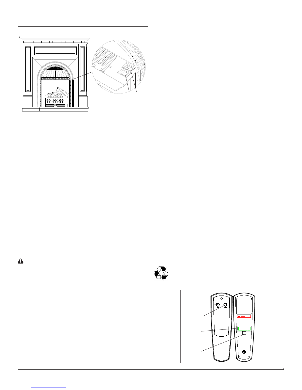
MANUAL CONTROLS
A. 3-Position Switch
The switch has two On positions marked with “ I ” and “ II ”.
The “ I ” position is for manual operation. In this position the
built-in remote control is bypassed. The “ II ” position is for
operating the unit with the provided remote control. When
in “ II ” position the unit is operated with the ON and OFF
buttons of the remote control. When the switch is in the
center “ O ” position the unit is off.
B. Heater Switch
The Heater Switch supplies power to the heating unit when
the 3-Position Switch (Figure 1A) is On (“I” or “II” positions).
Resetting the Temperature Cutoff Switch
Should the heater overheat, an automatic cut out will turn
the replace off and it will not come back on without being
reset. It can be reset by switching the 3-Position Switch to
Off and waiting ve (5) minutes before switching the unit
back on.
!
NOTE: If operating the unit with a remote control, the
remote control may require re-initializing after turning the
power off.
CAUTION: If you need to continuously reset the heater,
disconnect power and call Dimplex customer service at
1-888-DIMPLEX (1-888-346-7539).
Remote Control
The replace is supplied with a radio frequency integral
ON/OFF remote control (Figure 2). This remote control
has a range of approximately 50 feet (15.25 m), it does not
have to be pointed at the replace and can pass through
most obstacles (including walls). It is supplied with
one of hundreds of independent frequencies to prevent
interference with other units.
!
NOTE: Before attempting any operation with the
remote control, pull the plastic insulator strip out from
between the remote casing and battery cover (Figure 2).
!
NOTE: The remote control is an EEPROM system;
therefore if power is interrupted for whatever reason,
the built-in remote control receiver will hold the memory
of the remote’s radio frequency for up to 24 hours. The
remote should continue to operate the replace as
normal once unit is re-powered. Re-initialization of the
remote control to the replace should only be required
if there is a loss of power to the receiver for longer than
24 hours. (i.e. power failure, main power switch is turned
off).
!
NOTE: Ensure that the replace 3-Position Switch is
set to the remote control setting (I.E.. II).
To operate: push the ON button to turn replace on; push
the OFF button to turn replace off.
!
NOTE: Remote control only operates the main power
supply. Heat must still be controlled by switches on
replace.
Remote Control Initialization/Reprogramming
If the remote control or remote control receiver has been
replaced, follow these steps to initialize the remote control
and receiver:
Turn off power to replace.1.
Locate manual controls (Figure 1).2.
Set the 3-Position Switch to the remote position “II”.3.
Wait a minimum of ve (5) seconds and then re-acquire 4.
power to replace.
Within 10 seconds of re-acquiring power, press the ON 5.
button located on the remote control.
!
NOTE: You will have only 10 seconds to perform this
last step. Failure to do so will result in these steps
needing to be followed again.
This will synchronize the remote control and remote control
receiver.
Battery Replacement
To replace the battery:
Slide battery cover open on the remote control 1.
(Figure 3).
Install one (1) 12-Volt (A23) battery in the battery 2.
holder.
Close the battery cover3.
Battery must be recycled or disposed of properly.
Check with your Local Authority or Retailer for
recycling advice in your area.
Figure 2
On
Button
Off Button
Plastic
Strip
Battery
Cover
3
Page 4
MAINTENANCE
WARNING: Disconnect power before attempting
any maintenance or cleaning to reduce the risk of re,
electric shock or damage to persons.
CAUTION: Allow at least ve (5) minutes for the light
bulbs to cool before touching them to avoid accidental
burning of the skin.
The light bulbs need to be replaced when you notice a dark
section of the ame or when the clarity and detail of the log
ember bed exterior reduces. There are two (2) bulbs under
the ember bed, which generate the ames and embers.
Light Bulb Requirements
Quantity of two (2) clear chandelier or candelabra bulbs
with an E-12 (small) socket base, 60 Watt rating. Example:
GE 60BC or Philips 60 CTC.
Do not exceed 60 Watts per bulb
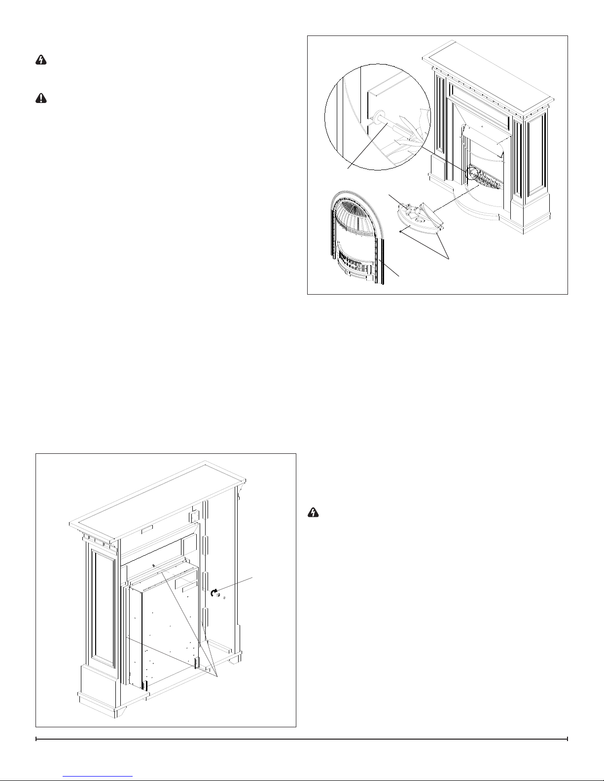
Bulb Replacement
The bulbs are located under the Ember Bed.
To gain access to the bulbs:
Remove the nut and washer as indicated in Figure 3 1.
and pull the front trim away from the replace (Figure
4).
Remove three (3) screws holding Ember Bed in place 2.
(Figure 4).
Release left side of Flicker Rod by turning rod and 3.
plastic bushing to match key slot of bracket. Pull
forward to clear bracket.
Remove the defective lamp(s) by unscrewing counter 4.
clockwise.
Figure 3
Figure 4
Flicker Rod
Ember Bed
Screws
Front Trim
Replace with a 60 Watt E12 clear chandelier or 5.
candelabra. Take care not to over-tighten the bulb.
Ret the Flicker Rod and Ember Bed, and secure with 6.
the screws removed in step 2.
Refit front trim and secure with washer and nut.7.
!
NOTE: To remove the rebox insert prior to repair,
remove the nine (9) black screws at the back of the
rebox as shown in Figure 3 and slide it out to the back.
Helpful Hints
It is a good idea to replace all light bulbs at one time if they
are close to the end of their rated life. Group replacement
will reduce the number of times you need to open the unit
to replace light bulbs.
4 www.dimplex.com
Washer
& Nut
Screws to
remove: 3 per
side and 3
along top edge
Cleaning
WARNING: Always disconnect from the power supply
before cleaning the replace.
For general cleaning use a soft clean duster – never use
abrasive cleaners. The glass viewing screen should be
cleaned carefully with a soft cloth. DO NOT use glass
cleaners.
To remove any accumulation of dust or uff, the soft brush
attachment of a vacuum cleaner should occasionally be
used to clean the outlet grill of the fan heater.
Page 5

EXPLODED PARTS DIAGRAM
6
8
7
9
4
3
14
1
13
2
Replacement Parts List
POWER CORD 1. . . . . . . . . . . . . . . . . . . 4100090104RP
FLICKER MOTOR2. . . . . . . . . . . . . . . . . . 2000210200RP
LIGHT HARNESS/ SOCKET3. . . . . . . . . 4200121000RP
PARTIALLY REFLECTIVE GLASS4. . . . . 5900860100RP
REMOTE CONTROL RECEIVER5. . . . . . 3000380200RP
REMOTE CONTROL6. . . . . . . . . . . . . . . 3000370500RP
3-POSITION SWITCH7. . . . . . . . . . . . . . 2800071100RP
HEATER SWITCH8. . . . . . . . . . . . . . . . . . 2800070900RP
10
5
11
12
HEATER ASSEMBLY9. . . . . . . . . . . . . . . 2200491200RP
MINI-BROCKTON TRIM10. . . . . . . . . . . . . 6905840184RP
CAPACITOR11. . . . . . . . . . . . . . . . . . . . . . 2300030100RP
TERMINAL BLOCK12. . . . . . . . . . . . . . . . . 4000070100RP
FLICKER ROD CONNECTOR13. . . . . . . . 8500680100RP
FLICKER ROD14. . . . . . . . . . . . . . . . . . . . 5900890100RP
LOG SET15. . . . . . . . . . . . . . . . . . . . . . . . . 0440090100RP
5
Page 6

WIRING DIAGRAM
6 www.dimplex.com
Page 7

FLICKER ROD/MOTOR REPLACEMENT
Tools Required: Phillips head Screwdriver
WARNING: If the replace was operating prior to
servicing allow at least 10 minutes for light bulbs and
heating elements to cool off to avoid accidental burning
of skin.
WARNING: Disconnect power before attempting any
maintenance or cleaning to reduce the risk of electric
shock or damage to persons.
Remove the nut and washer which secure the front trim 1.
to the mantel from behind (Figure 3).
Remove the front trim by pulling it away from the front 2.
of the mantel.
Remove the mesh curtains & rod from the mantel by 3.
pulling them away from the mantel, and set them aside
(Figure 5).
Remove 2 screws from the front of the replace which 4.
secure the rebox to the mantel base. These 2 screws
are in the bottom front of the rebox to the left and right
side (Figure 2).
From behind the mantel, remove 11 screws which se-5.
cure the rebox to the mantel (Figure 3).
Remove the rebox from behind the mantel and lay it 6.
on its back.
Remove the logset and front cover of the rebox by 7.
removing the 4 screws: 2 left and 2 right. They are
located on the lower, side panels of the rebox.
Grasp the rubber gasket connecting the icker rod and 8.
icker motor shaft on the right. Simultaneously pull and
twist the gasket (with the icker rod attached) away
from the motor. Once the rod and gasket are detached,
slide them to the right, guiding the rod out of the left
mounting bracket.
Figure 5
!
NOTE: When removing the Flicker Rod, damage may
occur if bent excessively or handled improperly. Ensure that
the Flicker Rod is straight and not crushed before reinstalling.
Turn the rebox and lay it on its right side, with the 9.
switch side towards the ceiling.
Remove only the 3 screws, closest to the icker motor, 10.
that secure the retaining bracket to the back panel (the
one that both the icker motor and the light sockets are
attached to). Also remove the 2 screws directly above
the rear left foot as well as the screw above and to the
right of those screws.
!
NOTE: Removing these should partially release the
mounting bracket, just enough to gently pull the motor
forward from the front and access the 2 motor mounting
screws.
Remove the two mounting screws on the icker motor.11.
Remove the lower Partially Reective Glass retaining 12.
bracket by removing the 2 mounting screws.
Slide the Partially Reective Glass down and place it 13.
in a safe place. This will give access to the terminal
block.
Loosen the screws that hold the old icker motor wires 14.
and replace with the wires for the new icker motor on
the terminal block.
Orient the new icker motor and mount to the mounting 15.
bracket.
Reassemble in the reverse order.16.
3-POSITION AND HEATER SWITCH
REPLACEMENT
Tools Required: Phillips head Screwdriver
Flat Head Screwdriver
WARNING: If the replace was operating prior to
servicing allow at least 10 minutes for light bulbs and
heating elements to cool off to avoid accidental burning
of skin.
WARNING: Disconnect power before attempting any
maintenance or cleaning to reduce the risk of electric
shock or damage to persons.
Remove the nut and washer which secure the front trim 1.
to the mantel from behind (Figure 3).
Remove the front trim by pulling it away from the front 2.
of the mantel.
Remove the mesh curtains & rod from the mantel by 3.
pulling them away from the mantel, and set them aside
(Figure 5).
Remove 2 screws from the front of the replace which 4.
secure the rebox to the mantel base. These 2 screws
are in the bottom front of the rebox to the left and right
side (Figure 2).
From behind the mantel, remove 11 screws which se-5.
cure the rebox to the mantel (Figure 3).
Remove the rebox from behind the mantel and lay it 6.
7
Page 8

Figure 6
Heater Housing
Switches
on its right side (with the switches at the bottom).
Remove the 2 screws from the upper back panel, 7.
located approximately 5 ½ inches down from the top of
the insert, (This is on your left side if facing the back of
the unit while on its side). These screws hold the back
part of the heater housing to the insert.
While carefully holding the heater housing from the 8.
front, remove the 2 screws from the top panel of the
insert which hold the top of the heater housing to the
insert.
!
NOTE: There are wires still attached to the heater
housing once the screws are removed.
Carefully lay the rebox insert on its back and pull the 9.
heater housing, with the heater assembly still attached,
out from the front of the rebox.
Move the heater housing 45 degrees and rest it on the 10.
work surface just beside the rebox.
Remove the 4 screws which mount the heater assem-11.
bly to the housing. This will allow you to remove the
heater assembly out of the housing so that you can
access the switches inside. (Figure 6)
Locate the defective switch mounted to the heater 12.
housing and disconnect the wiring clips and connections noting their original locations.
!
NOTE: A at head screwdriver can be used to gently
pry between the end of the connector and the switch to
release the wires.
Depress the retainer clips on the rear of the switch and 13.
push the switch out of the heater housing.
Properly orient the new switch and reconnect all of the 14.
wiring clips and connections.
Reassemble in the reverse order as above15.
Heater Assembly
HEATER ASSEMBLY REPLACEMENT
Tools Required: Phillips head Screwdriver
Flat Head Screwdriver
WARNING: If the replace was operating prior to
servicing allow at least 10 minutes for light bulbs and
heating elements to cool off to avoid accidental burning
of skin.
WARNING: Disconnect power before attempting any
maintenance or cleaning to reduce the risk of electric
shock or damage to persons.
Remove the nut and washer which secure the front trim 1.
to the mantel from behind (Figure 3).
Remove the front trim by pulling it away from the front 2.
of the mantel.
Remove the mesh curtains & rod from the mantel by 3.
pulling them away from the mantel, and set them aside
(Figure 5).
Remove 2 screws from the front of the replace which 4.
secure the rebox to the mantel base. These 2 screws
are in the bottom front of the rebox to the left and right
side (Figure 2).
From behind the mantel, remove 11 screws which se-5.
cure the rebox to the mantel (Figure 3).
Remove the rebox from behind the mantel and lay it 6.
on its right side (with the switches at the bottom).
Remove the 2 screws from the upper back panel, 7.
located approximately 5 ½ inches down from the top of
the insert, (This is on your left side if facing the back of
the unit while on its side). These screws hold the back
part of the heater housing to the insert.
While carefully holding the heater housing from the 8.
front, remove the 2 screws from the top panel of the
insert which hold the top of the heater housing to the
insert.
!
NOTE: There are wires still attached to the heater
housing once the screws are removed.
Carefully lay the rebox insert on its back and pull the 9.
heater housing, with the heater assembly still attached,
out from the front of the rebox.
Move the heater housing 45 degrees and rest it on the 10.
work surface just beside the rebox.
Remove the 4 screws which mount the heater assem-11.
Figure 7
8 www.dimplex.com
Page 9

bly to the housing. This will allow you to remove the
heater assembly out of the housing so that you can
access the switches inside. (Figure 6)
Disconnect wiring connections and connect to replace-12.
ment heater assembly noting their original locations.
Reassemble in the reverse order as above.13.
POWER CORD REPLACEMENT
Tools Required: Phillips head Screwdriver
Slip Joint Pliers
Flat Head Screwdriver
WARNING: If the replace was operating prior to
servicing allow at least 10 minutes for light bulbs and
heating elements to cool off to avoid accidental burning
of skin.
WARNING: Disconnect power before attempting any
maintenance or cleaning to reduce the risk of electric
shock or damage to persons.
Remove the nut and washer which secure the front trim 1.
to the mantel from behind (Figure 3).
Remove the front trim by pulling it away from the front 2.
of the mantel.
Remove the mesh curtains & rod from the mantel by 3.
pulling them away from the mantel, and set them aside
(Figure 5).
Remove 2 screws from the front of the replace which 4.
secure the rebox to the mantel base. These 2 screws
are in the bottom front of the rebox to the left and right
side (Figure 2).
From behind the mantel, remove 11 screws which se-5.
cure the rebox to the mantel (Figure 3).
Remove the rebox from behind the mantel and lay it 6.
on its back.
Remove the logset and front cover of the rebox by 7.
removing the 4 screws: 2 left and 2 right. They are
located on the lower, side panels of the rebox.
Grasp the rubber gasket connecting the icker rod and 8.
icker motor shaft on the right. Simultaneously pull and
twist the gasket (with the icker rod attached) away
from the motor. Once the rod and gasket are detached,
slide them to the right, guiding the rod out of the left
mounting bracket.
!
NOTE: When removing the Flicker Rod, damage may
occur if bent excessively or handled improperly. Ensure that
the Flicker Rod is straight and not crushed before reinstalling.
From beneath the rebox, remove the 2 screws that 9.
secure the power cord internal housing to the outer
frame. (Figure 7)
Disconnect wiring connections in the terminal block.10.
With needle nosed pliers, squeeze and push the grom-11.
met securing the power cord out of the casing.
Connect the new power cord into the same location.12.
Reassemble in the reverse order as above.13.
REMOTE CONTROL RECEIVER
REPLACEMENT
Tools Required: Phillips head Screwdriver
Slip Joint Pliers
Flat Head Screwdriver
WARNING: If the replace was operating prior to
servicing allow at least 10 minutes for light bulbs and
heating elements to cool off to avoid accidental burning
of skin.
WARNING: Disconnect power before attempting any
maintenance or cleaning to reduce the risk of electric
shock or damage to persons.
Remove the nut and washer which secure the front trim 1.
to the mantel from behind (Figure 3).
Remove the front trim by pulling it away from the front 2.
of the mantel.
Remove the mesh curtains & rod from the mantel by 3.
pulling them away from the mantel, and set them aside
(Figure 5).
Remove 2 screws from the front of the replace which 4.
secure the rebox to the mantel base. These 2 screws
are in the bottom front of the rebox to the left and right
side (Figure 2).
From behind the mantel, remove 11 screws which se-5.
cure the rebox to the mantel (Figure 3).
Remove the rebox from behind the mantel and lay it 6.
on its back.
Remove the logset and front cover of the rebox by 7.
removing the 4 screws: 2 left and 2 right. They are
located on the lower, side panels of the rebox.
Remove the lower Partially Reective Glass retaining 8.
bracket by removing the 2 mounting screws.
Slide the Partially Reective Glass down and place it 9.
in a safe place. This will give access to the Remote
Control Receiver.
Disconnect the wires noting their original location.10.
!
NOTE: A at head screwdriver can be used to gently
pry between the end of the connector and the receiver to
release the wires.
Remove the original remote control receiver from the 11.
mounting tabs located on the 4 corners of the receiver.
This can be done by cutting the tips of the tabs with
wire snips, or breaking the tips with pliers, then pulling
the receiver off the remainder of the tabs.
Remove the remainder of the original mounting tabs by 12.
pushing them out through the back panel of the replace. Replace with the new mounting tabs provided
with the new remote control receiver into the same
location on the back panel .
Gently push the replacement receiver onto the new 13.
mounting tabs.
Replace the wires into their original conguration.14.
Re-assemble the replace in reverse order.15.
9
Page 10

TROUBLESHOOTING GUIDE
PROBLEM CAUSE SOLUTION
General
Circuit breaker trips or fuse
blows when unit is turned on
Unit turns on or off by itself Remote Control has a similar frequency
Lights dim in room while the unit
is on
Power cord gets warm Normal Operation The power cord may get slightly warm to the touch
Appearance
Fireplace does not turn on Manually
Fireplace does not turn on using
the Remote Control
Flame Frozen Defective Flicker Motor Replace Flicker Motor
Flame not bright or ame not
visible
Log set dim, not glowing Burnt light bulbs Replace light bulbs
Flame Shutter Defective icker motor Replace icker motor
Short in unit wiring. Trace wiring in unit.
Improper circuit current rating Additional appliances may exceed the current rating
of the circuit breaker or fuse. Plug unit into another
outlet or install unit on a dedicated 15 amp circuit.
Replace Remote Control
to other remotes in the area.
Radio frequency disturbance from outside sources.
Defective Remote Control Receiver Replace Remote Control Receiver. Initialize Remote
Unit is drawing close to circuit current
rating
Defective power cord Replace power cord if cord gets hot to the touch.
Improper operation Refer to Operation Section
No incoming voltage from the electrical
wall socket
Defective 3-Position Switch Replace 3-Position Switch
Loose wiring Check wiring connections
Defective Remote Control Receiver Replace Remote Control Receiver. Initialize with
Improper operation Refer to Operation Section
Remote control not initialized to replace Initialize the Remote Control
Remote Control not working Install new battery into the Remote Control. Initialize
Loose wiring Check wiring connections
Burnt light bulbs Replace light bulbs
Loose wiring Check wiring connections
Defective light harness Replace light harness
Replace Remote Control and Remote Control Receiver. Initialize Remote Control and Receiver.
Control and Receiver.
Move the unit to another outlet or install unit on a dedicated 15 amp circuit
when the heater is on
Check Fuse/Breaker Panel
Remote Control.
Remote Control to Remote Control Receiver.
Replace Remote Control Receiver. Initialize Remote
Control and Remote Control Receiver.
10 www.dimplex.com
Page 11

Light leaking around the log set Log set not positioned properly Check log set for proper t
PROBLEM CAUSE SOLUTION
Heater
Heater is not turning off Improper operation Refer to Operation Section
Defective Heater Switch Replace Heater Switch
Defective Remote Control Receiver Replace Remote Control Receiver
Defective Heater Assembly Replace Heater Assembly
Heater is not turning on Improper operation Refer to Operation Section
Loose wiring Trace wiring in unit
Defective Heater Switch Replace Hater Switch
Defective Remote Control Receiver Replace Remote Control Receiver
Defective Heater Assembly Replace Heater Assembly
Heater is turning off after a
couple of minutes of operation
Heater emits an odor Normal Operation Normal operation is when the heater emits an odor
Heater fan turns on but heater
lacks heat
Heating element is glowing red Normal Operation Small glowing sections of the element are considered
Noise
Excessive noise with the heater onDirty Heater Assembly Ensure that exterior intake louvers and rebox cavity
Grinding or excessive noise with
the heater off
Build up of dirt/dust in Heater Assembly Ensure that exterior intake louvers and rebox cavity
are free of dirt/dust.
Defective Heater Assembly Replace Heater Assembly
for a brief period after the heater is initially turned on.
The heater is burning off any dust accumulated during
manufacturing or operation.
Defective Heater Assembly Replace Heater Assembly
Improper operation Refer to Operation Section
Loose wiring Trace wiring in unit
Defective Heater Assembly Replace Heater Assembly
normal.
Defective Heater Assembly If larger glowing sections are causing the heater to trip
the thermal cutout, unplug unit, discontinue use and
replace Heater Assembly.
are free of dirt/dust.
Defective Heater Assembly Replace Heater Assembly
Flicker rod hitting or rubbing against
internal components
Defective Flicker Motor Replace Flicker Motor
Ensure rod is straight and mounted properly in the
bracket, spinning freely away from other components.
Replace if necessary.
11
 Loading...