

Page 1

CFH60, CFH90 & CFH120
Tel:
+44
(0)191 490 1547
Fax:
+44 (0)191 477 5371
Email:
northernsales@thorneandderrick.co.uk
Website: www.heattracing.co.uk
www.thorneanderrick.co.uk
Electronic Wall Mounted Fan Heater
The product complies with the European Safety Standards EN60335-2-30 and the European Standard Electromagnetic Compatibility (EMC) EN55014,
EN60555-2 and EN60555-3. These cover the essential requirements of EEC Directives 2006/95/EC and 2004/108/EC
08/19511/1 (UK) Issue 1
Page 2
1
D2
D1
100mm
Min.
H
1000mm
Min.
2
70mm
500mm
Min.
CFH60 386 360 565 630
CFH90 386 360 565 630
CFH120 386 360 565 630
L
500mm
Min.
L H D1D2
3a 3b
1 2
o
45
Max.
2.0m MIN
70mm
4
1
2
x
3
y
5
6
z
w
x
y
Page 3

7
MLC MLC
CPC
L1 N L1 N
L3 L2
380 - 415V
3PN + E
380 - 415V
3PN + E
M
C
D
E
B
L3 L2
B
E
D
C
M
ECP
SU SU
MU
L1 N
L3 L2
380 - 415V
3PN + E
M
C
D
E
B
POWER IN
HEATER
B
US OU
T
B
US I
N
LED
PO
WER I
N
HEATER
B
US OUT
B
US I
N
LED
POWER IN
HEATER
B
US OU
T
B
US I
N
LED
380 - 415V
3PN + E
L3 L2
CFH60, CFH90 & CFH120
B
L1 N
E
M
POWER IN
HEATER
3 min
BUS OUT
BUS IN
LED
45 min
8
220 - 240V ~1PN + E 380 - 415V ~3PN + E
(FACTORY SUPPLIED)
BLUE
PINK
PINK
BLUE
BLUE
VIOLET
VIOLET
BROWN
BROWN
ORANGE
ORANGE
WHITE
WHITE
N
L1
L2
BLUE
PINK
PINK
BLUE
BLUE
VIOLET
VIOLET
BROWN
BROWN
WHITE
WHITE
N
L1
L2
9
L3
= CFH90 & CFH120
ORANGE
ORANGE
L3
Page 4

Dimplex Industrial Fan Heater
Models : CFH60, CFH90 & CFH120
IMPORTANT: THESE INSTRUCTIONS SHOULD BE READ CAREFULLY AND RETAINED FOR FUTURE REFERENCE
IMPORTANT SAFETY ADVICE
DO NOT COVER OR OBSTRUCT the air inlet or outlet grille.
ENSURE THE APPLIANCE IS EARTHED.
Always disconnect supply before working on the product.
Do not use this heater in areas where excessive dust
exists.
This heater must not be located immediately above or
below a fixed socket outlet or connection box.
This product should be mounted safely to a solid wall.
Ensure the supply cables are of adequate current carrying
capacity and are protected by a suitable fuse.
This appliance should only be connected to the fixed wiring
of the premises by means of conduit.
This product must not be subjected to water spray or
immersion.
If the appliance is mounted in a toilet or washroom, the
appliance should be mounted such that no part of it can
be touched by a person using a fixed bath or shower.
If the appliance is mounted in a toilet or washroom an
isolating switch must be provided outside the washroom
adjacent to the entrance door.
WARNING: Isolate electrical supply to ALL modular linked
units when carrying out maintenance.
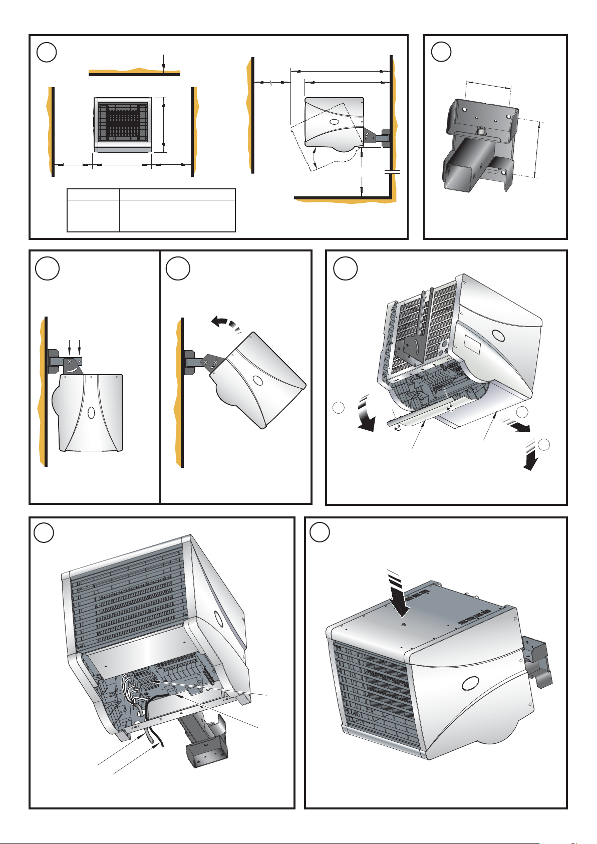
Wall Mounting
Remove the wall mounting bracket from the back of the heater
and using it as a guide (see Fig. 2) mark off the hole positions on
a suitable wall (a minimum height of 2 meters is required from
the floor level to the bottom of the bracket). Solid brick or concrete
block walls must be drilled and plugged. Fix the wall mounting
bracket to the wall and assemble the heater to the extension
tube using a bolt and wing nut fitted into hole 1 shown in Fig. 3a.
Rotate the heater as shown in Fig. 3b, and fix the heater into
position using the remaining bolt and wing nut in hole 2. Pivot
and rotate the heater into the desired position and tighten all
three wing nuts. A 6mm Allen key can be used as an aid to
tightening the bolts.
Electrical and Control connections
Note: The installation of this appliance should be carried out
by a competent electrician and be in accordance with the
current IEE wiring regulations.
All products are fitted with a microprocessor control. Electrical
power and control connections for all CFH models are made by
removing the control housing and bottom panel. The control
housing (‘y’ in Fig. 4) is detached by removing the two quick
release fasteners and hinging the housing as shown (see step
1 in Fig. 4). The bottom panel (‘x’ in Fig. 4) is detached by removing
two screws and lifting off as shown (see steps 2 & 3 in Fig. 4).
Note: A suitable local isolating switch must be provided in the
electrical supply circuit as close as possible to the heater with at
least 3mm clearance on each pole.
General
A range of robust, high power wall mounting fan heaters
designed to coordinate with the Dimplex range of Air Curtains,
providing environmental heating in commercial and light
industrial environments.
The heaters work by gradually raising the air temperature in the
building and should be positioned so as best to achieve an
even temperature distribution.
The product range has outputs of 6kW, 9kW and 12kW, and each
product contains on-board electronics that enables ‘daisy-chain’
linking to an electronic control panel (CFCH) or building energy
management system.
Connectivity between heater and control panel is achieved using
LAN (Local Area Network) cable i.e. CAT5, CAT5E or CAT6, pin
configuration is straight through 1 to 1.
The electronic controller has a number of features including
thermostatic control. For more details on these refer to the CFCH
instruction leaflet.
Model Heat Electrical Electrical Weight Min
Output Supply Load installed
(per phase) height
kW A kg m
220-240V~ 1PN 26.0
CFH60 3 / 6 13 2
380-415V~ 3PN 9.0
220-240V~ 1PN 38.8
CFH90 6 / 9 14 2
380-415V~ 3PN 13.3
220-240V~ 1PN 51.6
CFH120 6 / 12 14 2
380-415V~ 3PN 17.5
Wiring Diagrams - see Fig. 7
A - PCB
B - Mains in terminal blocks
C - Cut-out circuit
D - LAN Sockets
E - Elements
M - Motor
Remove the large knock-out from back panel of heater and feed
appropriate supply cable (see ‘x’ in Fig. 5) to terminal blocks ‘z’.
Make electrical connections as shown in Fig. 7 and fix the cable
in back panel using suitable cable gland (not supplied). By
removing one of the smaller knock-outs and using LAN cable
(see ‘y’ in Fig. 5) make the control connection to the BUS IN
socket ‘w’ also shown in Fig. 5. Fix this cable in the back panel
using a suitable cable gland (not supplied) and feed back to the
electronic control panel (CFCH) using suitable conduit if required.
Refer to CFCH Instructions for installation and connections of
electronic control panel. Replace the bottom panel and control
housing and switch on power to heater and installed electronic
control panel. Ensure that all control settings function correctly.
Note: The factory supplied unit can accept three phase voltage
of ~380-415V. For single phase ~220-240V refer to the electrical
wiring label (see Fig. 8) fixed to the underside of the bottom
panel. To change between different voltage systems, rearrange
the push on connections as per the required wiring diagram.
Page 5

Operation using Control Panel - CFCH
Tel:
+44
(0)191 490 1547
Fax:
+44 (0)191 477 5371
Email:
northernsales@thorneandderrick.co.uk
Website: www.heattracing.co.uk
www.thorneanderrick.co.uk
Maintenance
Switch on electrical supply to the fan heater and the electronic
control panel. When all units are powered up and there is a
connection between the controller and the master unit, an LED
will turn on in the controller to indicate the units are functioning.
Refer to the CFCH instruction leaflet on the operation of the
electronic control panel.
Delayed Shutdown
Door Switch (3min Runback): By wiring in a normally open contact
to the door switch connections shown in Fig. 7, the folowing
operation is achieved:
• Up to 1 minute after contact closed, unit runs at set
condition.
• Between 1 & 2 minutes. unit runs half & half settings.
• Between 2 & 3 minutes. unit runs fan only settings.
• Over 3 minutes. unit enters stand-by mode.
PIR Sensor (45min Runback): By changing the PCB mounted
links shown in Fig. 7 the runback timer will operate as follows:
• Up to 15 minutes after contact closed, unit runs at set
condition.
• Between 15 & 30 minutes. unit runs half & half settings.
• Between 30 & 45 minutes. unit runs fan only settings.
• Over 45 minutes. unit enters stand-by mode.
Modular Linking
A number of fan heaters can be connected together in a ‘daisy
chain’ fashion. A total of ten units can be controlled from a single
electronic control panel. The required connections can be made
in a daisy chain fashion as shown in Fig. 9. (References shown
below).
ECP - Electronic Control Panel
MU - Master Unit
SU - Slave Unit
MLC - Modular Linking Cable
CPC - Control Panel Cable
To make these connections remove one of the small knock-outs
and feed an appropriate LAN cable (not supplied) to the BUS
OUT control socket (‘D’ in Fig. 9) of the Master Unit. Fix this cable
in the back panel using suitable cable gland (not supplied).
Continue this process for all linked heaters. Replace the control
housing of each heater and power up all units. Ensure that all
control settings function correctly.
Thermal Safety Cut-out
The power supply to the heating elements will be interrupted if
one or a combination of the following abnormal events occurs:
1. Air inlet or outlet grilles are obstructed.
2. Internal ventilation is impaired due to build up of dust and
fluff.
3. Blower unit stalls.
Note: Before re-setting the cut-out, the reason for activation must
be determined and corrective action taken.
To reset the thermal safety cut-out, access reset button as shown
in Fig. 6 and push in direction of arrow.
WARNING: Disconnect electrical supply to all connected units
prior to carrying out maintenance.
Optimum performance and long service from this product will
only be realised if regular maintenance is carried out. Dimplex
recommends regular checks dependant on normal use or more
frequent checks where the unit is installed in arduous conditions
or used continually for more than 10 hours per day.
Standard Maintenance
Where the product is subject to use not exceeding 10 hours
per day:
Every 3 months the fan wheels, impellors, heating elements, air
inlet and outlet grilles should be cleaned, removing dust and
debris with a suitable soft brush.
Every 12 months all moving parts should be checked for free
running with appropriate remedy/adjustment made where
necessary.
Extended Maintenance
Where the product is subject to arduous conditions or is used
continually for more than 10 hours per day:
Each month the fan wheels, impellors, heating elements and
air inlet and outlet grilles should be checked and cleaned,
removing dust and debris with a suitable soft brush.
Every 6 months all moving parts should be checked for free
running with appropriate remedy/adjustment made where
necessary.
Recycling
For electrical products sold within the European Community.
At the end of the electrical products useful life it should
not be disposed of with household waste. Please
recycle where facilities exist. Check with your Local
Authority or retailer for recycling advice in your country.
Cleaning
WARNING: DISCONNECT SUPPLY before carrying out
maintenance.
External appearance can be maintained by wiping occasionally
with a damp cloth. For stain removal, a weak soap solution can
be applied with a cloth and the surface wiped dry. Care must be
taken to avoid any moisture ingress into the product.
After Sales Service
Your product is guaranteed for one year from the date of purchase.
Within this period, we undertake to repair or exchange this product
free of charge (excluding element & subject to availability)
provided it has been installed and operated in accordance with
these instructions.
Your rights under this guarantee are additional to your statutory
rights, which in turn are not affected by this guarantee.
Should you require after sales information or assistance with
this product please go to
find our self help guide by clicking on “After Sales” or ring our
helpdesk on 0845 600 5111 (UK) or 01 842 4833 (R.O.I.) .
Spare parts are also available on the website
www.dimplex.co.uk
Please retain your receipt as proof of purchase.
www.dimplex.co.uk where you will
 Loading...