

Page 1
Model: BUH19BWS
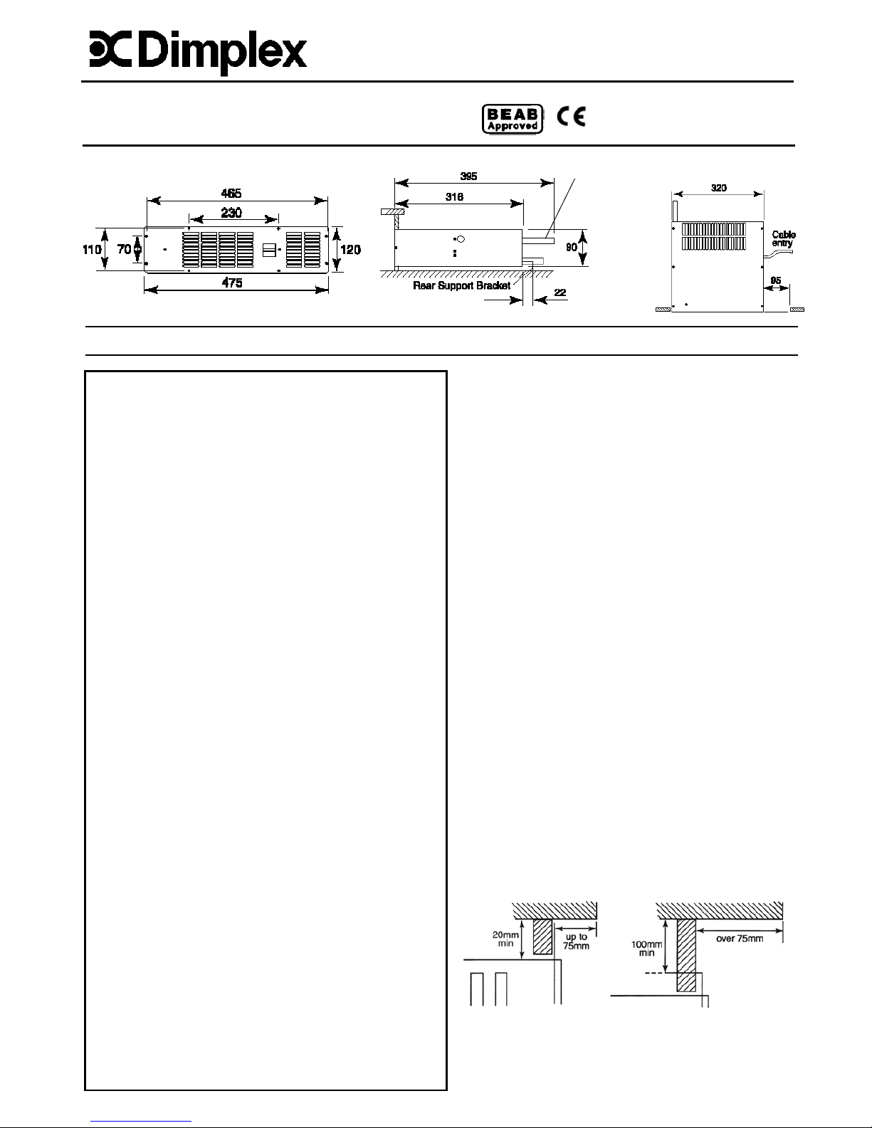
Dimensions
(millimetres)
General
This heater has been designed for fitting in the space behind
the plinth of floor standing kitchen units or other fitted
furniture units. It is recommended that the heater is not
installed under cupboards used for storing perishable goods.
This heater may be fitted in place of or in additio n to existing
radiators. Using the hot water from the central heating
system and a powerful electric faint will produce an average
2.0kW of heat into the room.
Installation
The heater is more easily fitted during the installation of new
furniture units, or in existing furniture units if they can be
temporarily moved from their position against the wall. If an
existing furniture unit cannot be moved, then it may be
necessary to remove the back of the unit in order to gain
access to carry out the wiring installation.
Before installing the unit consider the location with respect to
the following:
• The product has a depth of 395mm, the length of the
valves and flexible cable should also be taken in to
consideration.
• The electrical supply and cable length.
• Position of system pipework and flexible hose length.
• Position the heater to deliver heat effectively without
causing personal discomfort from overheating while
standing at work surfaces etc.
• If the overhang above the heater is greater than 75mm,
then a distance of at least 100mm must be maintained
between the overhang and the uppermost part of the
heater (see Fig. 1 below).
Fig. 1
Hydronic Base Unit Heater
Installation and Operating Instructions
08/18304/2 (30/04/09) Issue 2
THESE INSTRUCTIONS SHOULD BE READ CAREFULLY AND RETAINED FOR FUTURE REFERENCE
IMPORTANT SAFETY ADVICE
When using electrical appliances, basic precautions
should always be followed to reduce the risk of fire,
electrical shock, and injury to persons, including the
following:
• WARNING THE SURFACES OF THIS HEATER CAN BE
HOT
• This appliance is not intended for use by children or
other persons without assistance or supervision if
their physical, sensory or mental capabilities prevent
them from using it safely. Children should be
supervised to ensure that they do not play with the
appliance.
• If you use this heater in conjunction with an external
thermal control, a programme controller, a timer or any
other device which switches the he at on auto matically,
observe all safety warnings AT ALL TIMES since a fire
risk exists when the heater is accidentally co vered or
displaced.
• The installation of this product should be carried out
by an electrician or competent person and be in strict
accordance with the current IEE Wiring Regulations
and relevant Building Regulations.
• NEVER cover or obstruct in any way the heat outlet
slots at the front of the heater or the air inlet slots at
the top and rear of the heater.
• DO NOT cover the heater – Do not place material or
garments on the heater or obstruct the air circulation
around the heater
• Before connecting the heater check that the supply
voltage is the same as that stated on the heater.
• The heater must be installed in accordance with these
instructions.
• The heater should be installed and operated in the
horizontal position as shown in diagram above.
• The heater should be positioned in accordance to the
clearances stated in these instructions.
• DO NOT locate this heater immediately beneath a fixed
socket outlet.
• This appliance must be earthed.
Depth does not
include valves
and flexible pipe
Ensure
air inlet
grille is
clear
Page 2
Central heating design system
1. When fitting the appliance onto a central heating
system check that the boiler is capable of delivering
extra heat into the appliance by resizing the system.
The appliance will add an average of 2kW (6,830
Btu/Hr) onto the boiler sizing.
2. Due to the low water content of the heat exchanger
in the appliance compared to a panel radiator
system, an adequate flow of water should be
maintained to compensate for rapid cooling of the
water as it passes through the exchanger i.e.
maximum efficiency is gained if the appliance is
placed as near to the boiler as possible to give the
maximum pressure head across the appliance.
Installation procedure
Ensure that all packing items are removed (read any warning
labels carefully). Retain all packing for possible use, in the
event of moving or returning the heater to your supplier.
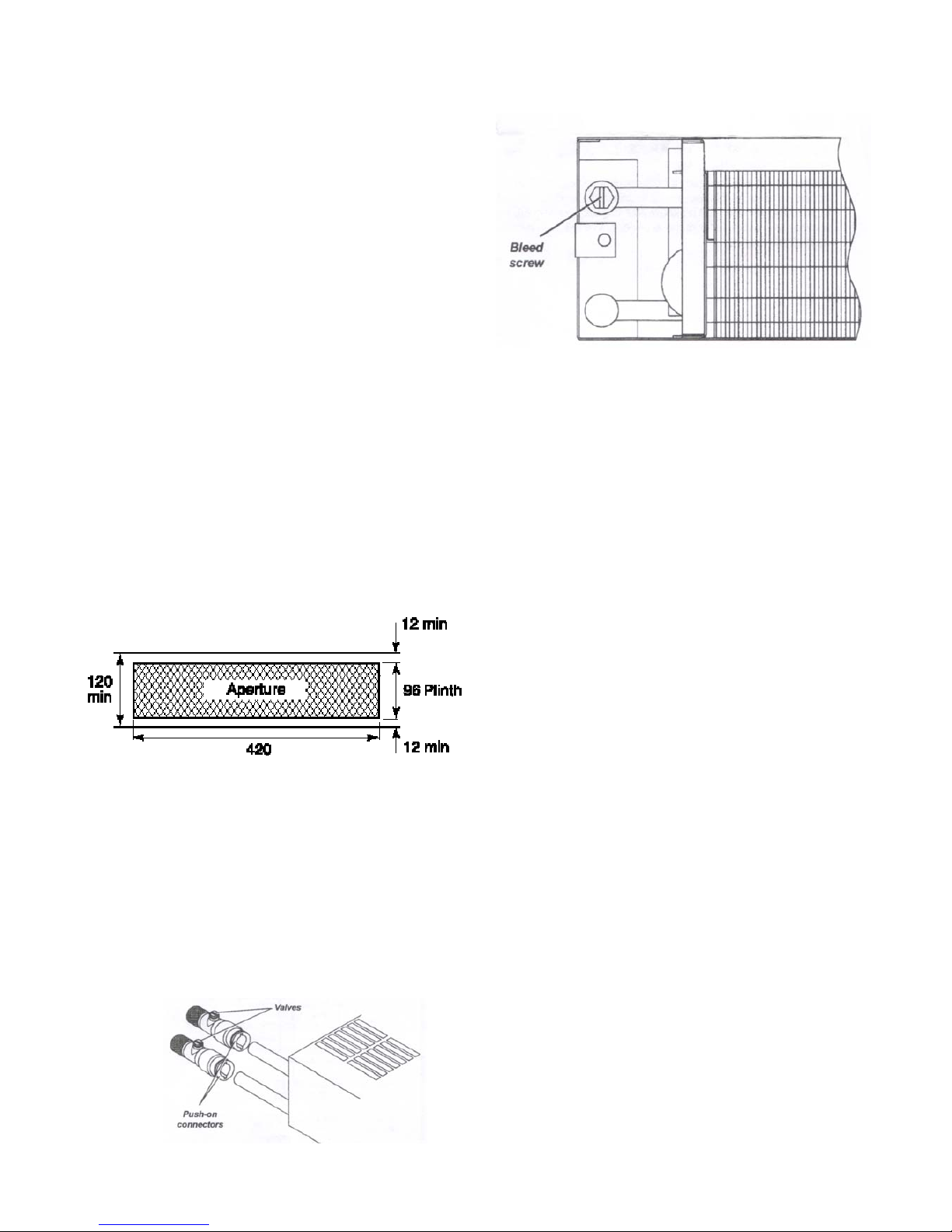
Cutting the aperture in the plinth
Cut aperture in furniture unit plinth to dimensions shown.
This must be positioned so that the minimum distance from
the bottom of the aperture to the top surface of any floor
covering is not less than 12mm and not more than 25mm
(see Fig. 2).
If an overhang above the heater is greater than 75mm, then
a distance of at least 100mm must be maintained between
the overhang and the uppermost part of the heater.
Water Connections
WARNING: Do NOT connect electricity supply when making
water connections.
Connect the flexible pipes to the system flow and return
pipes.
The appliance terminates in 15mm pipe tails (top pipe flow –
bottom pipe return). Connect the valve ends of the flexible
pipe to the rear of the appliance. (Note: The direction of flow
arrows on the valves are not significant in this application. )
(see Fig. 3).
Fig. 3
Fill and vent the system and bleed the air out of the heat.
exchanger using the bleed screw provided (located at the top
of the flow pipe).(see Fig. 4).
Fig. 4
Close the vent and check the appliance for water leaks. If
any water escapes from the bleed screw ensure ensure it
does not fall onto any electrical wiring or connections. After
bleeding the appliance ensure that electrical controls are
completely dry before connecting to the power supply.
Power supply connection
WARNING: THIS APPLIANCE MUST BE EARTHED
This heater must be used on an AC~ supply only and the
voltage marked on the heater must correspond with the
supply voltage.
The installation of this appliance should be carried out by a
an electrician or competent person in strict accordanc e with
the current IEE Wiring Regulations and relevat Building
Regulations.
Before undertaking installation work, ensure the electricity
supply is disconnected from any relevant wiring.
The appliance is fitted with 2 meters of flexible cable 3 x
0.75mm² for electrical connection. The cable may be used to
connect the heater to the fixed wiring of the premises
through a suitable connection box. The supply circuit to t he
heater must incorporate a double pole isolating switch having
a contact separation of at least 3mm. The power supply
cable should be routed through the plinth space to the
connection box, ensuring that the cable is left with enough
slack to allow removal of the appliance for maintenance. The
cable must be protected from any sharp edges.
Fitting the rear support bracket
The heater is supplied with a rear support bracket. Fit to the
back of the appliance with the two black screws supplied.
Adjust the rear support bracket so that the vertical distance
from the underside of the appliance to the bottom of the rear
support bracket equals the vertical distance from the floor in
the cupboard space to the bottom of the aperture opening.
The slots in the rear of the support bracket allow it to be
adjusted to the required height.
Fig. 2 (all dimensions in mm)
Page 3

Marking the fixing positions
Slide the heater in to position in the plinth aperture with the
front edge just behind the line of the plinth.
Note: Ensure that flexible pipes are not kinked and that th e
electrical cord is not in contact with hot surfaces.
Replace the plinth and bring the appliance forward so that
the front edge slightly projects through the plinth.
Position the grille in front of the heater and fix with two
screws (smaller screws).
Mark the eight fixing holes (two on each side, t wo on the top
and two on the bottom). Remove the grille and drill 2mm pilo t
holes.
Mounting the heater in to the plinth
Make sure the heater is adequately supported and that th e
air inlet slots are not obstructed. Fix the grille to the heater
and use the eight longer screws provided to secure the
heater to the plinth.
Operation
1. Switch on the electricity supply to the heater
2. Winter use for heating:
Set the Winter/Summer switch to (Winter position)
Select either low or boost fan speed on the changeover
switch depending on heat required.
3. Turn ON the central heating system.
4. As hot water reaches the heat exchanger the low limit.
Thermostat should cut in and the fan will start to operate
(set at 38ºC).
5. Summer use – cool blow.
The hydronic base unit heater may be used in Summer to
provide air circulation without heat.
Set the winter / Summer switch to (Summer position),
and Choose between low or boost fan speed.
In this position the fan will run at the selected speed until
manually reset.
Troubleshooting
Insufficient heat output from the heat exchanger may be
caused by:
• Airlock in the heat exchanger – (ISOLATE FROM
ELECTRICAL SUPPLY)
Remove the grille and bleed the appliance as in the
Water Connections’ section.
• Hot water temperature too low – the boiler thermostat
may need increasing.
• Bulk of the hot water circulating through the radiators –
rebalance by closing back lockshield valves on radiators
to increase water flow through the appliance.
• Dirty heat exchanger.
Wiring Diagram
Fig. 5
Winter/Summer switch
Boost/low speed switch
Page 4

Cleaning and User Maintenance
WARNING: DISCONNECT POWER SUPPLY before
carrying out any maintenance.
General cleaning
External appearance can be maintained by wiping
occasionally with a damp cloth; for stain rem oval, weak soa p
solution can be applied, then wipe dry.
Internal cleaning and maintenance
From time to time it may be necessary to remove the heater
from the furniture unit so that the interior of the heater and
the heater compartment can be cleared of any dust or fluff.
To remove, unscrew the eight fixing screws and withdraw the
appliance from the plinth. Remove the top cover and gently
remove dust with a soft brush and a vacuum cleaner, taking
care not to damage the fan or heat exchanger.
Do NOT tamper with any electrical parts.
Remount the heater in the plinth ensuring the rear support
bracket is still adjusted correctly, the flexible pipes are not
kinked and the mains cable is not touching any hot or sharp
surfaces.
Recycling
For electrical products sold within the European
Community.
At the end of the electrical products useful life it should
not be disposed of with household waste.
Please recycle where facilities exist. Check
with your Local Authority or retailer for
recycling advice in your country.
After Sales Service
Your product is guaranteed for one year from the date of
purchase.
Within this period, we undertake to repair or exchange thi s
product free of charge (subject to availability) provided it has
been installed and operated in accordance with these
instructions.
Your rights under this guarantee are additional to your
statutory rights, which in turn are not affected by this
guarantee.
Should you require after sales information or assistance with
this product please go to www.dimplex.co.uk
where you will
find our self help guide by clicking on “After Sales” or ring our
helpdesk on 0845 600 5111 (UK) or 01 842 4833 (R.O.I.) .
Spare parts are also available on the website
www.dimplex.co.uk
Please retain your receipt as proof of purchase.
The product complies with the European Safety Standards EN60335-2-30 and the European Standard Electromagnetic Compatibility (EMC)
EN55014, EN60555-2 and EN60555-3. These cover the essential requirements of EEC Directives 2006/95/EC and 2004/108/EC
Dimplex
Millbrook House
Grange Drive
Hedge End
Southampton
Hampshire. SO30 2DF
: Tel. 0845 600 5111
Fax. 01489 773050
WEBSITE www.dimplex.co.uk
Republic of Ireland Tel. 01 8424833
[c] GDC Group Ltd.
All rights reserved. Material contained in this publication may not be reproduced in whole or in part, without prior permission in writing of Dimplex.
A division of GDC Group Ltd.
 Loading...