

Page 1
1
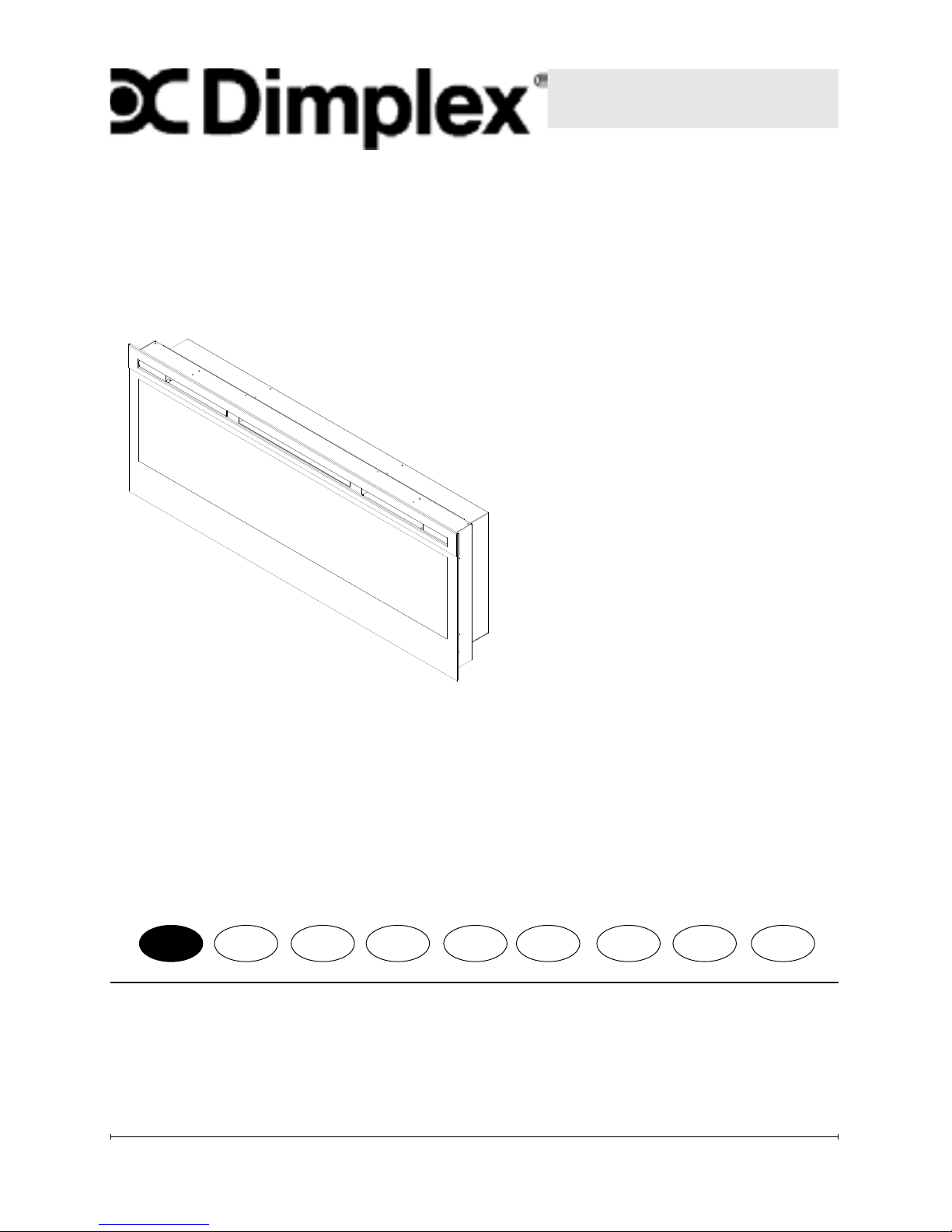
Owner’s Manual
Model
BLF50-UK
BELFORD
08/53087/0 (UK) Issue 1
IMPORTANT SAFETY INFORMATION: Always read this manual rst
before attempting to install or use this replace. For your safety, always
comply with all warnings and safety instructions contained in this manual
to prevent personal injury or property damage.
EN
Page 2
2 www.dimplex.co.uk
3
Table of Contents
Always use a qualied technician
or service agency to repair
this replace.
Welcome & Congratulations
Thank you and congratulations for
choosing to purchase an electric
replace from Dimplex, the world
leader in electric replaces.
Please carefully read and save
these instructions.
CAUTION: Read all
instructions and warnings
carefully before starting
installation. Failure to follow
these instructions may result
in a possible electric shock,
re hazard and will void
the warranty.
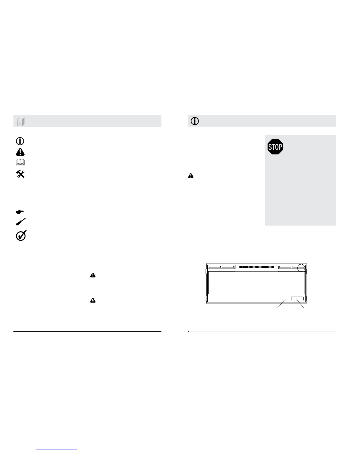
Please record your model and
serial numbers below for future
reference: model and serial
numbers can be found on the
Model and Serial Number Label
of your replace.
!
NOTE: Procedures and
techniques that are considered
important enough to
emphasize.
CAUTION: Procedures
and techniques which, if not
carefully followed, will result in
damage to the equipment.
WARNING: Procedures
and techniques which, if not
carefully followed, will expose
the user to the risk of re,
serious injury, or death.
Serial Number
Label
Rating Label
Welcome & Congratulations .................3
IMPORTANT SAFETY INSTRUCTIONS .......4
Quick Reference Guide ....................7
Fireplace Installation ......................8
Site Selection .................................. 8
Surface Installation .............................. 9
In-wall Recessed Installation - 100mm Deep ..........11
Flush Mounted Installation - 200mm Deep ........... 12
Front Glass Installation .......................... 13
Operation ..............................15
Maintenance ...........................17
Warranty ..............................18
NO NEED TO RETURN
TO THE STORE
Questions With the Assembly?
Require Parts Information?
Product Under Manufacturer’s
Warranty?
Call your local dealer
Please have your model
number and product serial
number ready. (See below)
Page 3

4 www.dimplex.co.uk
5
IMPORTANT SAFETY INSTRUCTIONS
IMPORTANT SAFETY INSTRUCTIONS
Read all instructions before
using this appliance.
When using electrical appliances, basic precautions
should always be followed to
reduce the risk of re, electrical shock and injury to persons, including the following:
1. If the appliance is damaged, check with the sup-
plier before installation
and operation.
2. Do not use outdoors.
3. Do not use in the imme-
diate surroundings of a
bath, shower or swimming pool.
4. Do not locate the appliance immediately below a
xed socket outlet or connection box.
5. This appliance can be
used by children aged
form 8 years and above
and persons with reduced
physical, sensory or mental capabilities or lack of
experience and knowl-
edge if they have been
given supervision or in-
struction concerning use
of the appliance in a safe
way and understand the
hazards involved. Children shall not play with
the appliance. Cleaning
and user maintenance
shall not be made by Children without supervision.
6. Children of less than 3
years should be kept
away unless continuously supervised. Chil-
dren aged from 3 years
and less than 8 years
shall only switch on/off
the appliance provided
that it has been placed
or installed in its intended
normal operating position
and they have been given
supervision or instruction
concerning use of the appliance in a safe way and
understanding the hazards involved. Children
aged from 3 years and
less than 8 years shall not
plug in, regulate and clean
the appliance or perform
user maintenance.
7. Do not use this appliance
in series with a thermal
control, a program controller, a timer or any other device that switches
on the heat automatically, since a re risk exists
when the appliance is accidentally covered or displaced.
8. This appliance is not
equipped with a device
to control the room temperature. Do not use this
appliance in small rooms
when they are occupied
by persons not capable of
leaving the room on their
own, unless constant supervision is provided.
9. Ensure that furniture, curtains or other combustible
material are positioned no
closer than 1 metre from
the appliance.
10. In the event of a fault
unplug the appliance.
11. Unplug the appliance
when not required for long
periods.
12. Although this appli-
ance complies with safety
standards, we do not rec-
ommend its use on deep
pile carpets or on long
hair type of rugs.
13. The appliance must
be positioned so that the
plug is accessible.
14. If the supply cord is
damaged it must be re-
placed by the manufacturer or service agent or a
similarly qualied person
in order to avoid a hazard.
15. Keep the supply cord
away from the front of the
appliance.
WARNING: In order to
avoid overheating, do not
cover the appliance. Do not
Page 4
6 www.dimplex.co.uk
7
Quick Reference Guide
Figure 1
① The electrical information
regarding your electric replace can
be found on the rating label located
on the front of the unit, behind the
glass.
Before installation, please record your
replace's serial number below for
future reference.
② If you have any technical
questions or concerns regarding the
operation of your electric replace,
or require service contact customer
service.
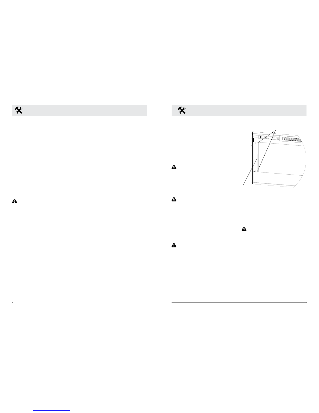
③ For dimensions of your replace,
refer to Figure 1.
3" (7.6 cm)
50
5
16
" (128 cm)
19
1
2
(49.5 cm)
46" (116 cm)
48
1
2
" (123 cm)
7"
(17.8 cm)
3
13
16
"
(9.7 cm)
18"
(45.7 cm)
16"
(40.6 cm)
place material or garments
on the appliance, or obstruct
the air circulation around
the appliance, for instance
by curtains or furniture, as
this could cause overheating
and a re risk.
WARNING: In order to
avoid a hazard due to inadvertent resetting of the
thermal cut-out, this appliance must not be supplied
through an external switching device, such as a timer,
or connected to a circuit that
is regularly switched on and
off by the utility.
CAUTION: Some parts
of this product can become
very hot and cause burns.
Particular attention has to
be given where children and
vulnerable people are pres-
ent.
IMPORTANT SAFETY INSTRUCTIONS
SAVE THESE INSTRUCTIONS
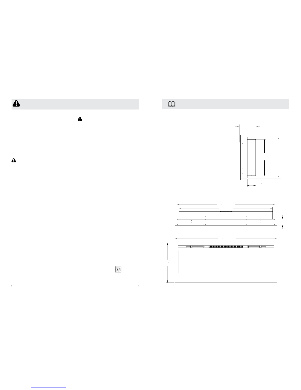
The heater carries the Warning Symbol
indicating that it must not be covered
Page 5
8 www.dimplex.co.uk
9
Site Selection
Review and consider all of the
following conditions for installation:
• Dimensions of the unit: 128cm
x 49.5cm
• Unit requires a minimum of two
(2) wall studs in order to ensure
a secure installation
Three possible installation
methods:
• Installation method: Surface
mount; In-wall Recessed; or
Flush mount
• Hardwired or plug-in method
WARNING: Ensure the power
cord is not installed so that it
is pinched or against a sharp
edge and ensure that the
power cord is stored or secured
to avoid tripping or snagging to
reduce the risk of re, electric
shock or injury to persons.
Construction and electrical
outlet wiring must comply
with local building codes and
other applicable regulations to
reduce the risk of re, electric
shock and injury to persons.
1. Select a location that is not
susceptible to moisture and
is away from drapes, furniture
and high trafc.
Fireplace Installation
2. For ease of electrical
hook up you may wish to
locate the replace near an
existing outlet (for plug-in
convenience).
!
NOTE 1: A 13 Amp, 230 Volt
circuit is required. A dedicated
circuit is preferred but not
essential in all cases. A
dedicated circuit will be
required if, after installation,
the circuit breaker trips or
fuse blows on a regular basis
when the heater is operating.
Additional appliances on the
same circuit may exceed the
current rating of the circuit
breaker.
3. Remove replace, front
glass and hardware from box
and remove all packaging
materials before installation.
4. Store the replace in a safe,
dry and dust free location until
you are ready to install the
replace.
Fireplace Installation
The replace is packaged with
a three prong plug installed for
plug-in convenience. Hard wiring
the replace is also an option
by removing the plug from the
factory tted cord and completing
the wiring according to National
and Local Elecrical Codes.
WARNING: Do not attempt to
wire your own new outlets or
circuits. To reduce the risk of
re, electric shock or injury to
persons, always use a licensed
electrician.
WARNING: Ensure that the
3-Position Switch is set to the
Off position ("O") and that the
circuit on which the replace is
to be installed has the power
cut off at the service panel until
installation is complete.
Surface Installation
CAUTION: Two people may
be required for various steps
of this procedure.
1. Choose a location for
mounting the unit.
2. Choose your method of
supplying power to the unit:
• Plug in to an existing outlet
or install an outlet nearby.
• Hard wire the replace.
Figure 2
Partially
Reective Glass
Glass Bracket
Bracket Screws
!
NOTE: Hard wiring can
be done by removing the plug
from the factory tted cord and
completing the wiring according
to National and Local Elecrical
Codes.
WARNING: Do not attempt
to wire your own new outlets or
circuits. To reduce the risk of re,
electric shock or injury to persons,
always use a licensed electrician.
Ensure that the 3-Position Switch is
set to the Off position ("O") and that
the circuit on which the replace is
to be installed has the power cut off
at the service panel until installation
is complete.
3. Remove the partially
reective glass from the
replace:
Page 6
10 www.dimplex.co.uk
11
5. Mark the location of four (4)
screw locations on the wall
(through key-holes).
CAUTION: If installing unit on
a wall that is constructed of
drywall ensure that appropriate
wall anchors are used and at
least one is located into a stud.
6. Remove fireplace from wall
and store in a safe place
away from traffic.
7. Screw all four (4) supplied #8,
3.8 cm square head mounting
screws and washers into
the wall and/or wall anchors
leaving 6.5 mm of thread.
8. Align chosen key-holes with
screws and hang replace
on the wall. Screw heads
and washers will t through
key-holes and replace will
slide down into place (screws
will slide into narrow part of
key-holes).
9. Tighten all four (4) mounting
screws down on replace
chassis.
10. Screw the two (2) supplied
#8 square head screws
through two of the permanent
mounting holes which align
with a wall stud.
11. Carefully replace and install
• Lay replace on its back.
• Remove two (2) Phillips
screws from each of the two
(2) glass brackets (Figure 2).
• Remove glass brackets.
• With one hand keeping
pressure on the partially
reective glass, tilt the
replace upright and slightly
forward to allow the partially
reective glass to fall out of
the inside framing.
• Remove partially reective
glass from replace.
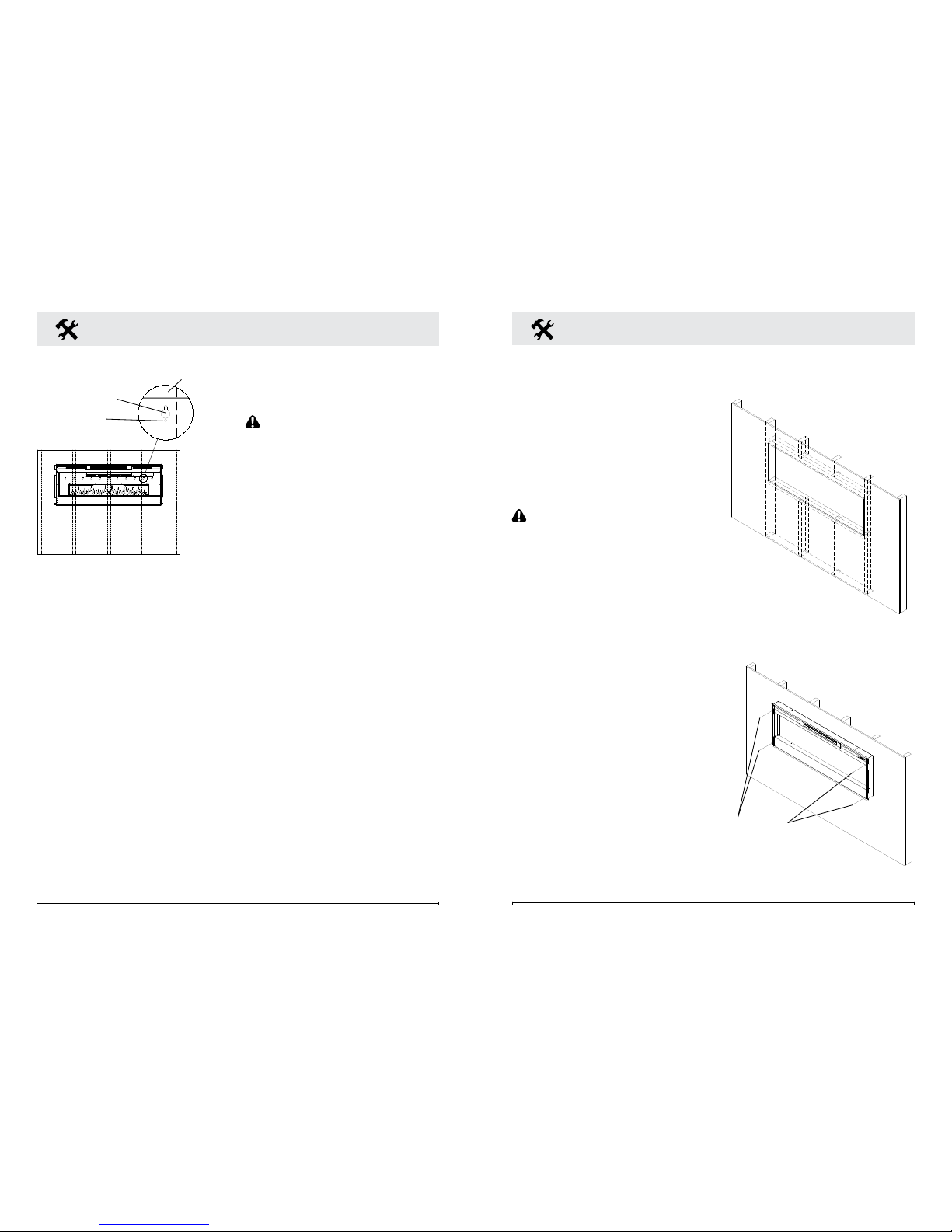
4. Position the replace on a wall
at the position where it will be
mounted (Figure 3). Use a
bubble level (one is supplied)
to ensure that replace is level
on the wall.
Fireplace Installation
Figure 3
Key-hole
Wall stud
Permanent
mounting hole
Fireplace Installation
partially reflective glass and
glass brackets using screws
from step 1.
12. Refer to Front Glass
Installation section, for nal
installation procedures.
In-wall Recessed
Installation - 100mm Deep
CAUTION: Two people may
be required for various steps
of this procedure.
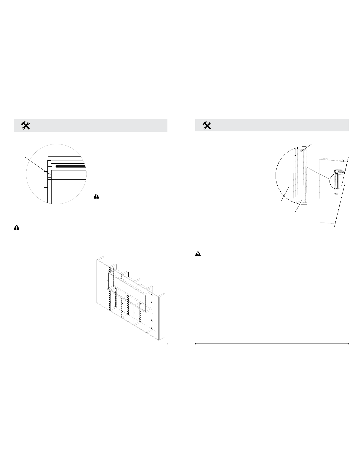
1. Prepare a wall with a framed
opening of 118.1 cm wide x
42 cm high (Figure 4).
!
NOTE: The sizing has allowed
for 6.4mm around the replace
insert for ease of installation. This
replace does not require any
additional venting.
2. Choose your method of
supplying power to the unit:
• Plug in (you may run the
power cord out of the framed
wall opening to an existing
outlet or install an outlet on
a nearby wall stud within the
wall).
• Hard wire the replace.
!
NOTE: Hard wiring can
be done by removing the plug
from the factory tted cord and
Figure 5
Mounting
holes
Figure 4
Page 7
12 www.dimplex.co.uk
13
Fireplace Installation
completing the wiring according
to National and Local Elecrical
Codes.
WARNING: Do not attempt
to wire your own new outlets or
circuits. To reduce the risk of re,
electric shock or injury to persons,
always use a licensed electrician.
Ensure that the 3-Position Switch is
set to the Off position ("O") and that
the circuit on which the replace is
to be installed has the power cut off
at the service panel until installation
is complete.
3. Lift replace and insert into
opening (Figure 5).
4. Use bubble level (supplied) to
level the replace within the
framing. Adjust as required.
5. Drive four (4) supplied
mounting screws through
the four (4) mounting holes
located in each corner of the
replace chassis, into wall
studs (Figure 6).
6. Refer to Front Glass
Installation section, for nal
installation procedures.
Flush Mounted
Installation - 200mm Deep
CAUTION: Two people may
be required for various steps
of this procedure.
1. Prepare a wall with a framed
opening of 124.5 cm wide x
47 cm high (Figure 7).
!
NOTE: The sizing has allowed
for 6.4mm around the replace
Figure 6
Mounting
hole
Figure 7
insert for ease of installation. This
replace does not require any
additional venting.
2. Choose your method of
supplying power to the unit:
• Plug in (you may run the
power cord out of the framed
wall opening to an existing
outlet or install an outlet on
a nearby wall stud within the
wall).
• Hard wire the replace.
!
NOTE: Hard wiring can
be done by removing the plug
from the factory tted cord and
completing the wiring according
to National and Local Elecrical
Codes.
WARNING: Do not attempt
to wire your own new outlets or
circuits. To reduce the risk of re,
electric shock or injury to persons,
always use a licensed electrician.
Ensure that the 3-Position Switch is
set to the Off position ("O") and that
the circuit on which the replace is
to be installed has the power cut off
at the service panel until installation
is complete.
3. Lift replace and insert into
opening. The replace's
mounting trim should be ush
against the wall (Figure 8).
Fireplace Installation
4. Use bubble level (supplied) to
level the replace within the
framing. Adjust as required.
5. Drive four (4) supplied
mounting screws through the
four (4) mounting holes located
on the inside surface of the
replace chassis, into wall
studs (Figure 8).
6. Refer to Front Glass
Installation section, for nal
installation procedures.
Front Glass Installation
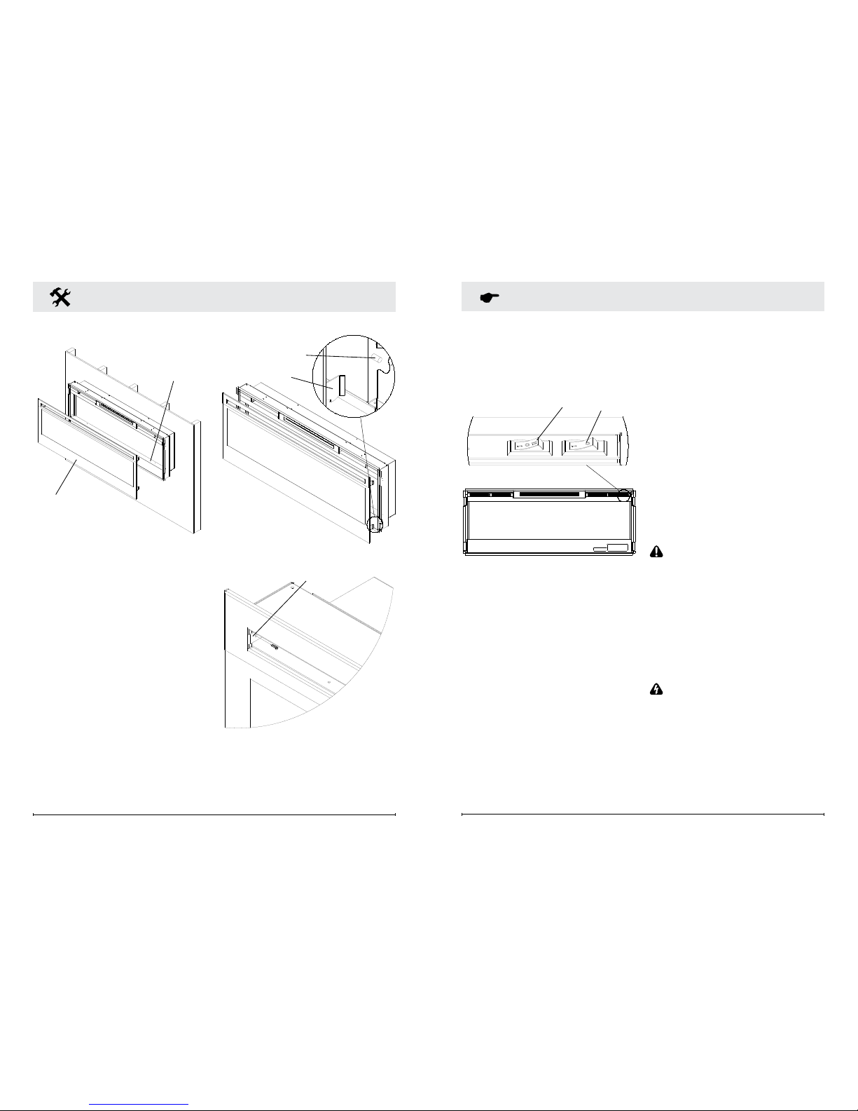
1. Evenly distribute supplied
glass rock on the front tray of
the fireplace (Figure 9).
2. Carefully mount front glass
assembly so that the front
Figure 8
Mounting hole
Mounting hole
Wall
surface
Page 8
14 www.dimplex.co.uk
15
Fireplace Installation
glass hooks (4) hang on the
front glass mounts on the
fireplace (4) (Figure 10).
3. Use the supplied two (2)
Phillips sheet metal screws
to fasten the glass assembly
tabs to the fireplace (Figure
11).
4. Ensure the fireplace's
3-Position Switch is switched
to the Off position ("O").
5. If unit is not hard-wired, plug
fireplace into a 13 Amp, 230
Volt outlet (refer to NOTE 1).
Figure 9
Front tray
Front glass
assembly
Figure 10
Hooks (4)
Mounts (4)
Figure 11
Tab
Operation
The manual controls for the
electric replace are located on
the right side of the unit and inside
the air intake slot (Figure 12).
A. 3-Position Switch
The switch has two (2) On
positions marked with “I” and
“II”. The “I” position is for manual
operation. In this position
the built-in remote control is
bypassed.
The “II” position is for operating
the unit with the provided remote
control. When in “II” position
the unit is operated with the ON
and OFF buttons of the remote
control.
When the switch is in the center
(“O”) position the unit is off.
Figure 12
B
A
B. Heat On/Off Switch
The Heat On/Off Switch supplies
power to the heater fan and the
heater element.
Resetting the Temperature
Cutoff Switch
Should the heater overheat, an
automatic cut out will turn the
replace off and it will not come
back on without being reset. It
can be reset by switching the
3-Position Switch to Off and
waiting ve (5) minutes before
switching the unit back on.
CAUTION: If you need to
continuously reset the heater,
disconnect power and contact
your local dealer.
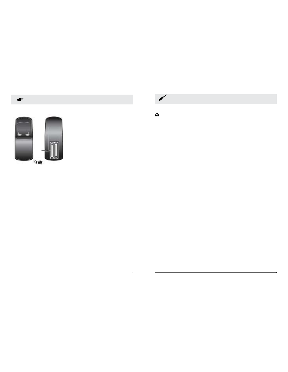
Remote Control (Figure 13)
The replace is supplied with an
integrated on/off remote control.
Where the maximum rage of use
is ~15m.
WARNING: It takes time for
the receiver to respond to the
remote control. Do not press the
buttons more than once within
two seconds for correct operation.
!
NOTE: Ensure that the
replace 3-Position Switch
is set to the remote control
setting ("II").
Page 9
16 www.dimplex.co.uk
17
Operation
Figure 13
To operate, push the ON button
to turn replace on, push the OFF
button to turn the replace off.
Battery Replacement
To replace the battery:
1. Slide battery cover open
on the back of the remote
control.
2. Install AAA batteries into the
remote control.
3. Replace the battery cover.
Discard leaky batteries. Dispose
of batteries in the proper manner
according to provincial and local
regulations. Any battery may leak
electrolyte if mixed with a different
battery type, if inserted incorrectly,
if all the batteries are not replaced
at the same time, if disposed of in
a re, or if an attempt is make to
charge a battery not intended to
be recharged.
Maintenance
WARNING: Disconnect
power before attempting any
maintenance or cleaning to
reduce the risk of re, electric
shock or damage to persons.
Partially Reective Glass
Cleaning
The partially reective glass is
cleaned in the factory during
the assembly operation. During
shipment, installation, handling,
etc., the partially reective glass
may collect dust particles; these
can be removed by dusting lightly
with a clean dry cloth.
To remove ngerprints or other
marks, the partially reective
glass can be cleaned with a damp
cloth. The partially reective glass
should be completely dried with
a lint free cloth to prevent water
spots. To prevent scratching, do
not use abrasive cleaners.
Fireplace Surface
Cleaning
Use only a damp cloth to clean
painted surfaces of the replace.
Do not use abrasive cleaners.
Servicing
Except for installation and
cleaning described in this
manual, an authorized service
representative should perform
any other servicing.
Page 10
18 www.dimplex.co.uk
19
obligation, or liability in connection
with said product.
*Light bulbs are not covered in the
warranty.
Service
Contact your local dealer for
service or warranty information.
Recycling
For electrical products sold
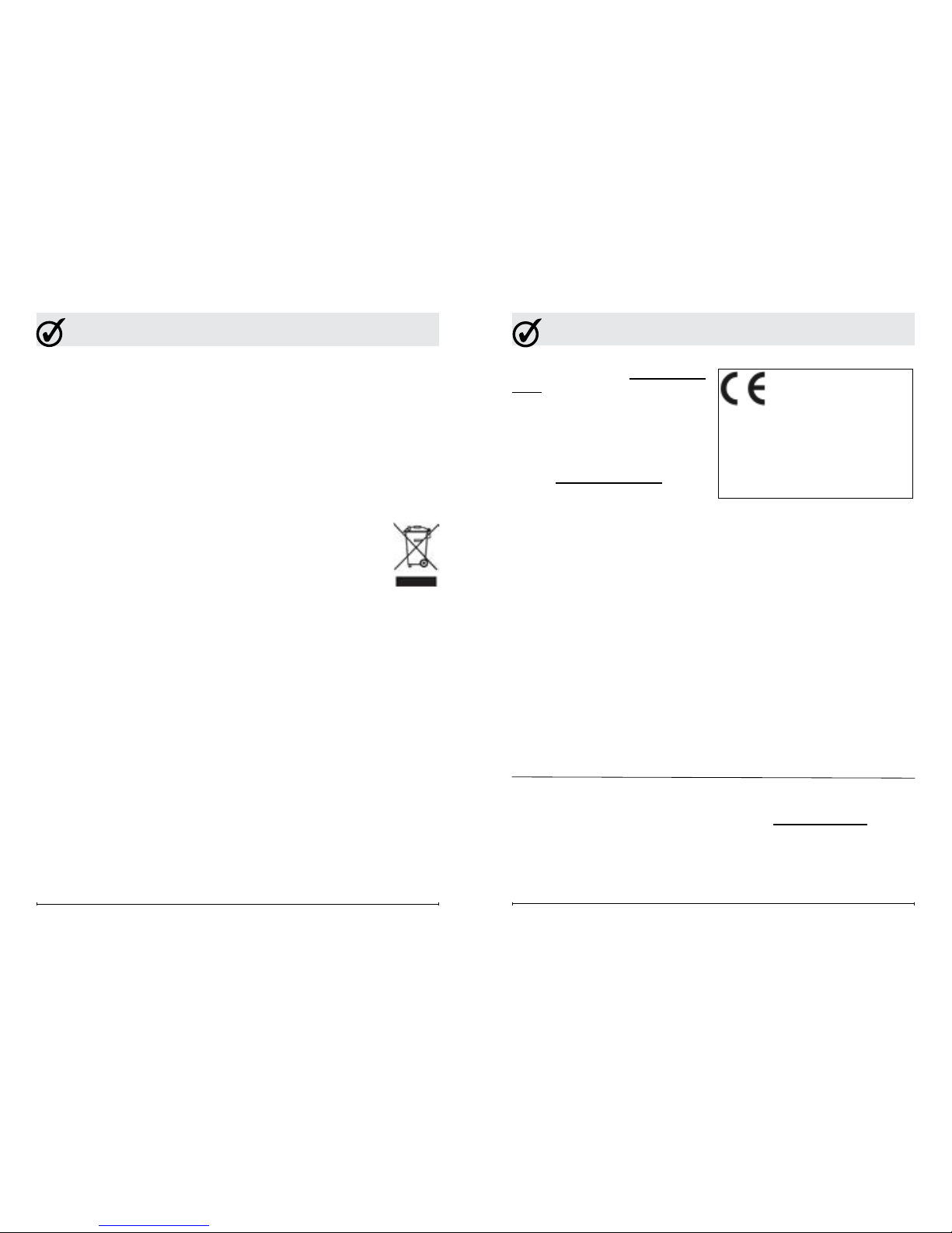
in the European Community.
At the end of the electrical
product’s useful life it should
not be disposed of with
household waste. Please
recycle where facilities exist.
Check with your Local Authority
or retailer for recycling advice in
your country.
Warranty
Dimplex Electric Fireplaces are tested
and inspected prior to shipment and
are guaranteed from defect to the
purchaser of each new product. Any
part which proves to be defective in
material or workmanship under normal
use within one year will be repaired
or replaced without charge.* The
Company will not be responsible for
any expense incurred for installation,
removal for service, or transportation
costs. Any such defect should be
brought to the attention of the Dealer
where the product was purchased
and is authorized to repair or replace
within the terms of this warranty.
The Company’s only obligation
under this warranty will be at its
sole option to repair or replace any
part proving defective or to refund
the purchase price thereof.
The owner/user assumes all other
risks, if any, including the risk of any
direct, indirect or consequential loss
or damage arising out of the use of or
inability to use the product.
The warranty will not apply if, in
the sole judgment of the Company,
damage or failure has resulted from
accident, alteration, misuse, abuse,
incorrect installation, or operation on
an incorrect power source.
The foregoing is in lieu of all other
warranties expressed, implied, or
statutory, and the Company neither
assumes, nor authorizes any
person to assume for it any other
The product complies
with the European Safety
Standard EN60335-2-30
and the European Standard for
Electromagnetic Compatibility
(EMC) EN55014, EN61000 and
EN50366 which cover the essential
requirements of EEC Directives
2006/95 and 2004/108.
After Sales Service
Your product is guaranteed for one
year from the date of purchase.
Within this period, we undertake to
repair or exchange this product free
of charge (subject to availability)
provided it has been installed and
operated in accordance with these
instructions.
Your rights under this guarantee are
additional to your statutory rights,
which in turn are not affected by this
guarantee.
Should you require after sales
information or assistance with this
product please go to www.dimplex.
co.uk where you will nd our self help
guide by clicking on “After Sales” or
ring our helpdesk on 0844 879 3588
(UK) or 01 842 4833 (R.O.I.) .
Spare parts are also available on the
website :
www.dimplex.co.uk
Please retain your receipt as proof of
purchase.
DIMPLEX
MILLBROOK HOUSE
GRANGE DRIVE
HEDGE END
SOUTHAMPTON
SO30 2DF
TEL: 0844 879 3588
FAX: 0844 879 3583
WEBSITE: www.dimplex.co.uk
Republic of Ireland Tel.01 8424833
[c] GDC Group Ltd,
All rights reserved. Material contained in this publication may not be reproduced in whole or in part, without prior
permission in writing of Dimplex.
A division of GDC Group Ltd,
Warranty
 Loading...