

Page 1

INSTALLATION GUIDE FOR THE
ELECTRIC FIREPLACE
MODEL NUMBERS:
BF33ST/DX
BF39ST/DX
BF45ST/DX
7206350200REV06
Page 2

CONTENTS
PAGE 1 Listings and Code Approvals
PAGE 1 Model Specifications
PAGE 1 Step-by-Step Installation
Section A
PAGE 2 Framing
Section B
PAGE 2 Recommended Power Supply Wire
Specifications
PAGE 2 Recommended Wire and Fusing
Requirements
PAGE 3 Voltage Selector Switch Location
PAGE 3 Mounting Flanges
Section C
PAGE 4 Factory Setting Wiring 240 Volt
(Without Main Power Wall Switch)
PAGE 5 Factory Setting Wiring 120 volt
(Without Main Power Wall Switch)
Section D
PAGE 6 - 7 Main Power Wall Switch Wiring for 240 Volt
PAGE 8 - 9 Main Power Wall Switch Wiring for 120 Volt
Section E
PAGE 10 - 11 Heater Wall Switch Wiring for 120/240 Volt
PAGE 12 - 13 Wall Mounted Thermostat Wiring for
120/240 Volt
PAGE 14 - 15 Flame Override Switch Wiring for 120/240
Volt
Section F
PAGE 16 - 18 Wiring Diagrams
Page 3
LISTINGS AND CODE APPROVALS
The BF series fireplaces have been tested in accordance with the UL 2021 and CSA C22.2 No. 46 standards for
fixed and location-dedicated electric room heaters.
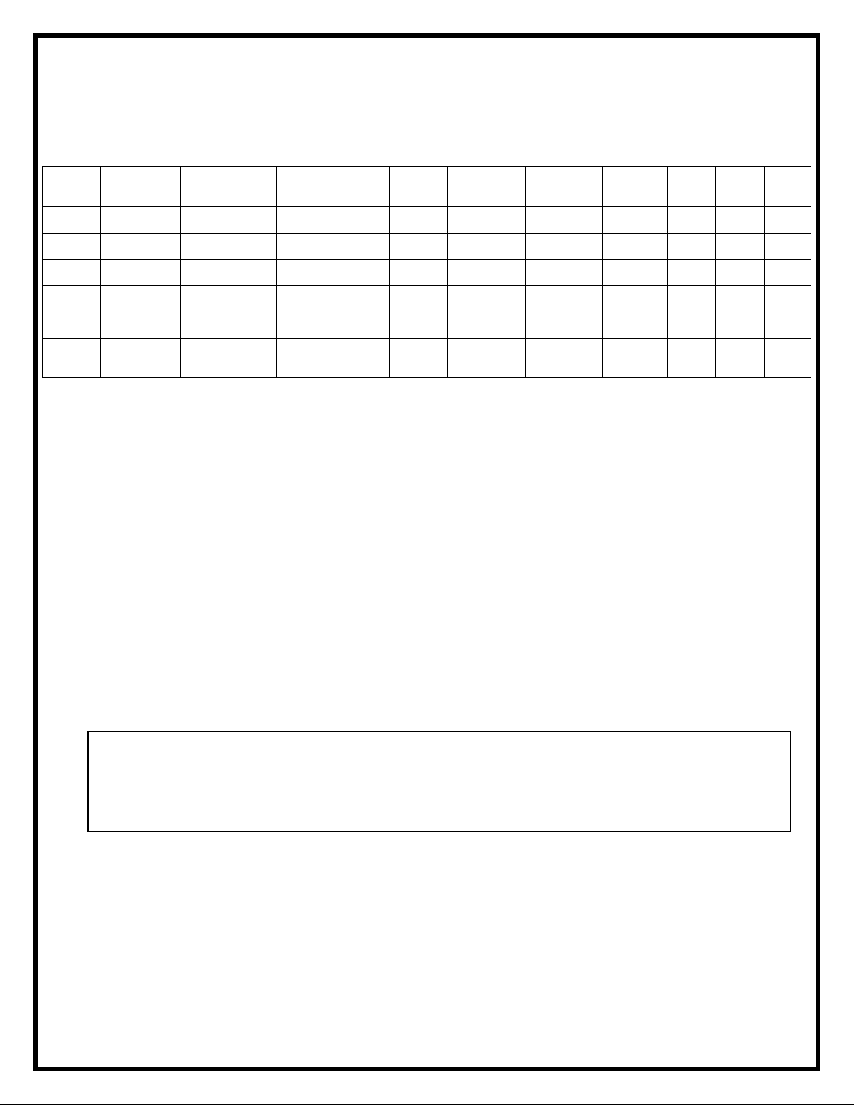
MODEL SPECIFICATIONS
Model
Number
BF33ST
BF33DX 33” Deluxe
BF39ST
BF39DX 39” Deluxe
BF45ST
BF45DX 45” Deluxe
Description Voltage Volts Rated Power Watts
33”
Standard
39”
Standard
45”
Standard
120/120/208/
240
120/120/208/
240
120/120/208/
240
120/120/208
/240
120/120/208/
240
120/120/208/
240
245/1440/2100/
2700
245/1440/2100/
2700
245/1440/2100/
2700
245/1440/2100/
2700
245/1440/2100/
2700
245/1440/2100/
2700
Remote
Control
Option Option N/A 2.0 12.0 10.10 11.25
Option Option Included 2.0 12.0 10.10 11.25
Option Option N/A 2.0 12.0 10.10 11.25
Option Option Included 2.0 12.0 10.10 11.25
Option Option N/A 2.0 12.0 10.10 11.25
Option Option Included 2.0
Wall
Thermostat
Refractory
Brick Look
AMPS
No Heat
120 Volt
NOTE: Power ratings shown include the light bulbs and motors (275 watts)
WARNING
The installation of the fireplace unit must comply with the applicable Local and/or National
Electrical Codes and utility requirements. This installation should be entrusted to duly qualified
personnel where required by law.
AMPS
120
Volt
12.0
AMPS
208
Volt
10.10 11.25
AMPS
240
Volt
STEP-BY-STEP INSTALLATION (Note: Please read all instructions before installing)
1. Rough in framing opening following the recommended dimensions located in
(Section A: Framing).
2. Allow 8” of service cable for connecting power supply wire to junction box on fireplace
when installing before finishing wall. Allow up to 4 feet of service cable for connecting
power supply wire to junction box on fireplace when installing after finishing wall.
Remove the outer jacket and strip the individual conductors ½” from the end.
3. Loosen the screw securing the junction box cover and remove the cover.
4. Remove knockouts if necessary or use the provided cable clamp.
5. Place unit in position in the framed opening, level with shims if necessary and attach
unit to frame using mounting flanges provided (see figure 3 on page 3).
6. Unit is factory wired for 208/240 volt power supply (see figure 1 on page 3). If 120 volt
operation is required, slide the switch and reconfigure the wiring
(see figure 2 on page 3). Wires L1, L2, N & G are attached to the rear of the junction
box cable clamp for easy access.
Note
If wiring unit to operate with NO heat a dedicated circuit may not be required.
7. Wire a dedicated, properly fused circuit with a 15amp rating for the appropriate voltage
(120, 208/240). (see Section C for factory setting wiring)
8. Make wall switch and or wall mounted thermostat connections as outlined in Section D:
Wiring.
9. Place all connectors inside the unit and secure the junction box cover to unit. Ensure
that the cable clamp grips only the jacket of service cable, thermostat and if applicable
wall switch lines.
1
Page 4
WARNING
A
Ensure method of installation does NOT obscure the air intake slots on bottom front of unit
in any manner. (see diagram in Section A)
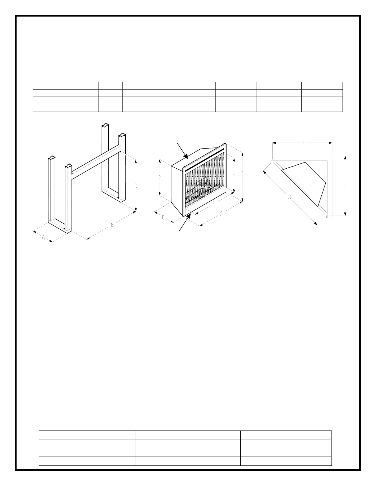
SECTION A: FRAMING
Dimensions
MODEL A B C D E F G H I J K L
BF33ST/DX 15.0” 33.5” 29.5” 23.0” 14.3” 29.6” 32.8” 18.8” 28.5” 48.0” 34.0” 34.0”
BF39ST/DX 16.0” 39.5” 33.5” 26.6” 15.3” 36.0” 38.7” 22.8” 32.7” 54.0” 38.0” 38.0”
BF45ST/DX 16.0” 45.5” 33.5” 26.6” 15.3” 42.0” 44.7” 22.8” 32.7” 60.0” 42.0” 42.0”
Rough-in framing dimensions
Top Surface
ir Intake Slots
Firebox dimensions
Rough-in corner framing
This fireplace is a zero clearance design. No combustibles can be placed on the top surface of the fireplace.
Combustibles may be installed to the edge of the unit. Four mounting flanges on the sides of the unit are provided
to facilitate installation. Insulation and vapor barrier should be placed a minimum of 2 inches from the unit.
SECTION B: RECOMMENDED POWER SUPPLY WIRE SPECIFICATIONS
For 120 volt installations use two conductor, non-metallic sheath cable with ground wire (3
wires total) for the incoming power supply on fireplace inserts. Use the appropriate wire to
meet local and national electrical codes for rated power consumption.
For 208 / 240 volt installations use three conductor, non-metallic sheath cable with ground
wire (4 wires total) for the incoming power supply on fireplace inserts. Use the appropriate wire
to meet local and national electrical codes for rated power consumption.
Two conductor, non-metallic sheath cable with ground wire (3 wires total) is recommended for
installation of a wall mounted thermostat and/or wall switch for use on fireplace inserts. Use
appropriate wire to meet local and national electrical codes for rated power consumption. All
wire gauges should match the recommended wire sizes shown below.
RECOMMENDED WIRE AND FUSING REQUIREMENTS
VOLTS WIRE GAUGE FUSE RATING
120 VOLT 12 GAUGE 15 AMP
208 VOLT 12 GAUGE 15 AMP
240 VOLT 12 GAUGE 15 AMP
2
Page 5
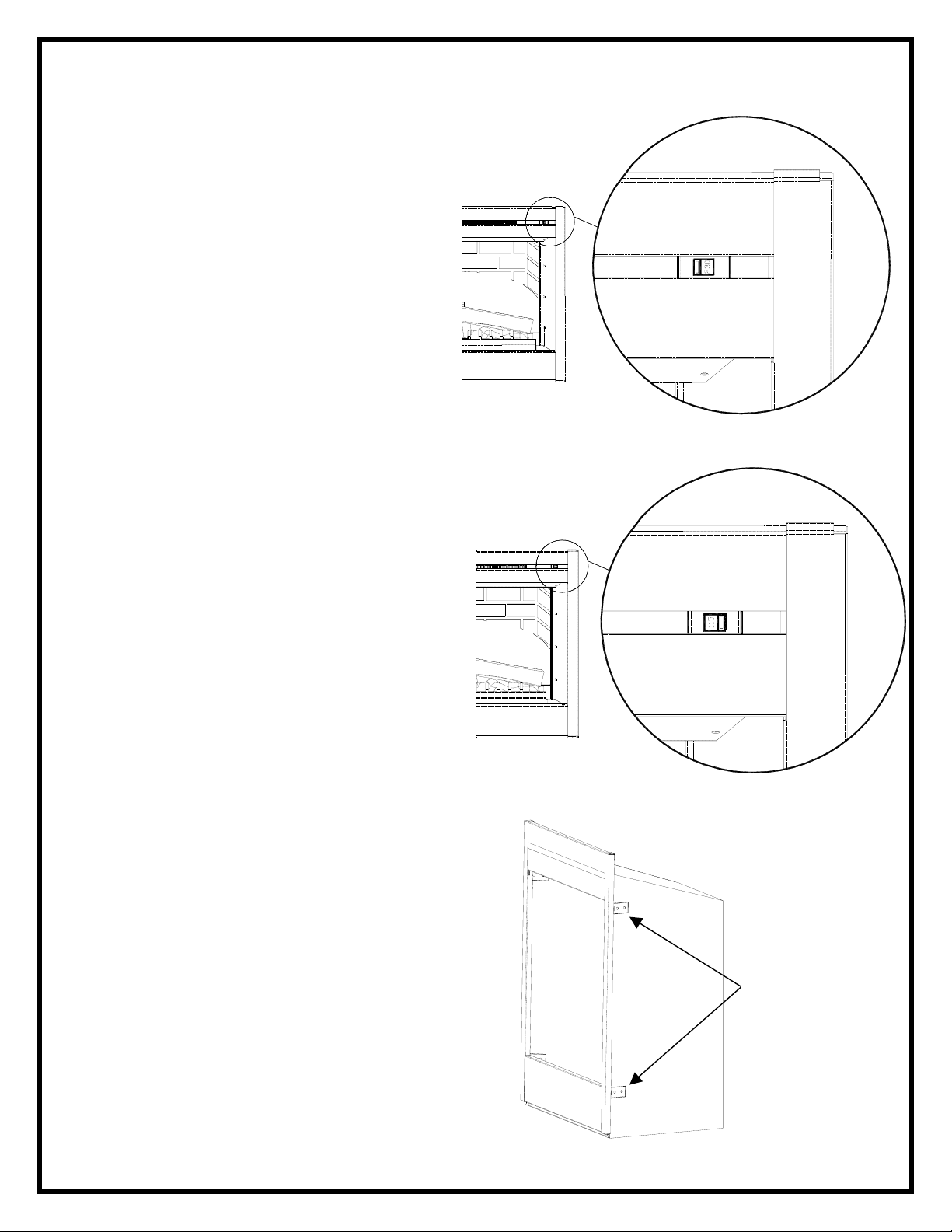
VOLTAGE SELECTOR SWITCH LOCATION
IMPORTANT:
Ensure that the incoming power supply
voltage matches the setting of the voltage
selector switch.
NOTE:
The voltage selector switch is located
inside the exhaust panel on the top
right hand corner.
CAUTION:
When changing the voltage selector
switch from 240 volts to 120 volts
ensure that the power supply is turned
off.
NOTE:
Carefully insert a flat headed
screwdriver inside the exhaust panel
to change the switch from 240 volts
(230 position) to 120 volts (115 position).
When wiring the unit for 208 / 240 volts
the voltage selector switch should be
in the 230 volt position. (see figure 1)
When wiring the unit for 120 volts
the voltage selector switch should be
in the 115 volt position. (see figure 2)
MOUNTING FLANGES
There are two mounting flanges located
on each side of the fireplace insert.
Bend tabs and mount to framing using
suitable hardware.
FIGURE 1
FIGURE 2
FIGURE 3
Mounting
Flanges
3
Page 6
X
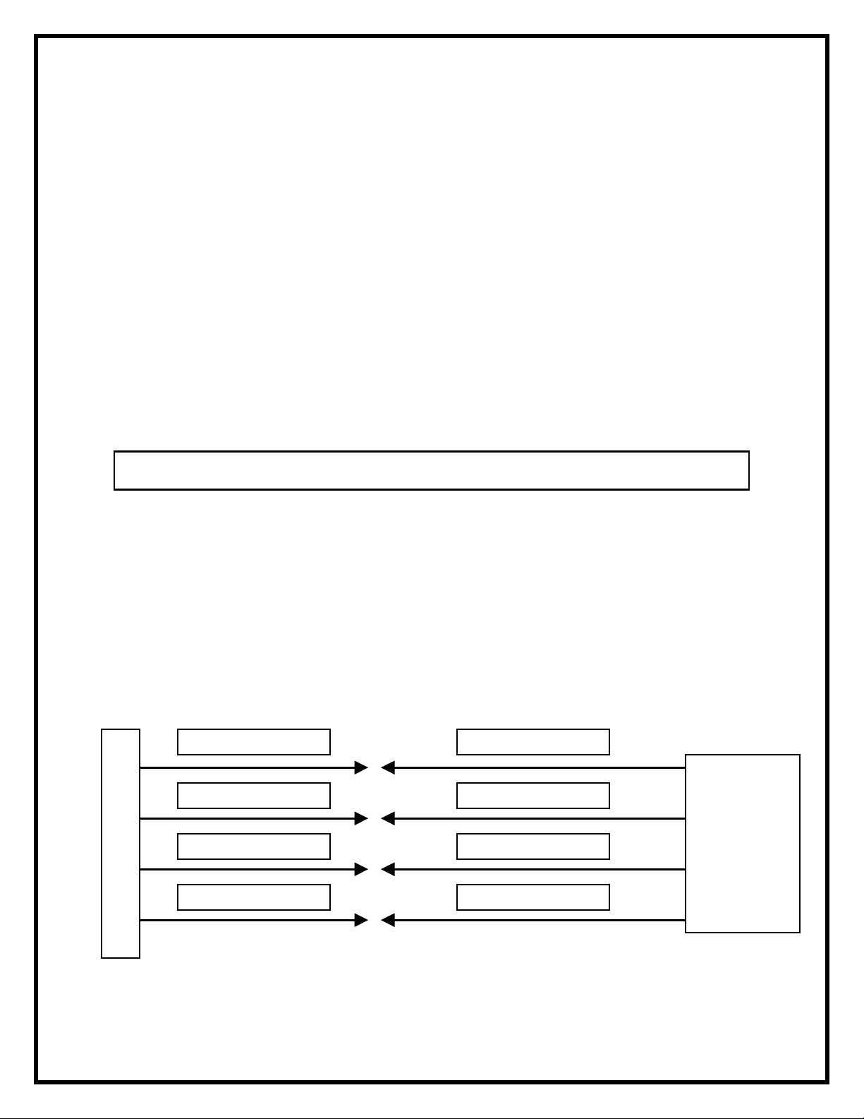
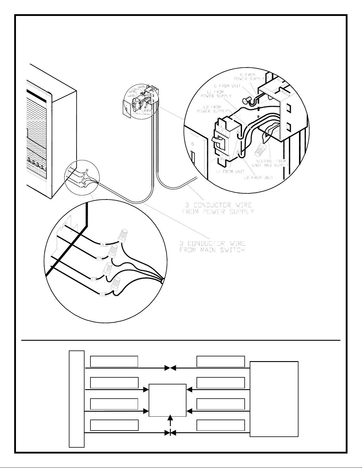
SECTION C: FACTORY SETTING WIRING
(WITHOUT MAIN POWER WALL SWITCH)
IMPORTANT:
The unit is factory configured for 208/240 volt operation
NOTE:
Use 3 conductor wire with ground (4 wires total) from the power supply (breaker panel) to the
junction box on the unit.
NOTE:
All wiring must be completed prior to installing the unit.
NOTE:
Ensure that the voltage selector switch is in the proper position for the required supply voltage
prior to connecting the unit to the power supply.
240 VOLT INSTALLATION
1. Locate the voltage selector switch inside the exhaust panel on the top right hand
corner of the unit. (see figure 1 on page 3)
2. Ensure that the switch is in the 240 volt position. (230 is printed on switch)
3. Loosen the screw securing the junction box cover and remove the cover.
4. Remove the knockouts (if necessary) or use the provided cable clamp.
5. Pull out the four wires marked L1, L2, N, and G.
6. Connect the black L1 wire from the unit to the black L1 from the power supply.
7. Connect the red L2 wire from the unit to the red L2 from the power supply.
8. Connect the white N wire from the unit to the to the white neutral from the power
supply.
9. Connect the green ground wire from the unit to the ground from the power supply.
10. Ensure that all connections are tight.
11. Insert all the wiring back into the unit and secure with a cable clam p.
FIREPLACE JUNCTION BO
WHITE WIRE - N
RED WIRE – L2
BLACK WIRE – L1
GREEN WIRE - G
WHITE WIRE - N
RED WIRE –L2
BLACK WIRE –L1
GROUND WIRE - G
240 V
POWER
SUPPLY
(BREAKER
PANEL)
4
Page 7
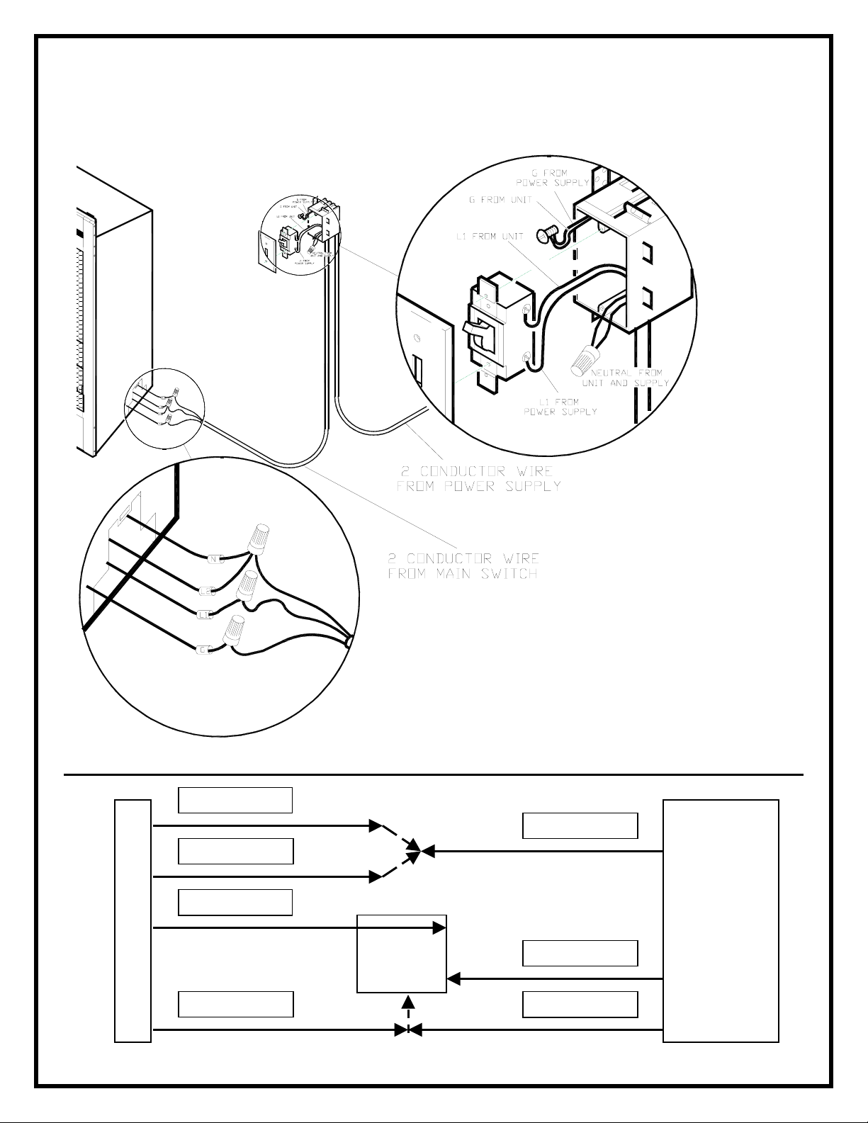
SECTION C: FACTORY SETTING WIRING
X
–
(WITHOUT MAIN POWER WALL SWITCH)
IMPORTANT:
The unit is factory configured for 208/240 volt operation
NOTE:
Use 2 conductor wire with ground (3 wires total) from the power supply (breaker panel) to the
junction box on the unit.
NOTE:
All wiring must be completed prior to installing the unit.
NOTE:
Ensure that the voltage selector switch is in the proper position for the required supply voltage
prior to connecting the unit to the power supply.
120 VOLT INSTALLATION
1. Locate the voltage selector switch inside the exhaust panel on the top right hand corner
of the unit. (see figure 2 on page 3)
2. Flip the switch from 240 volt to 120 volt configuration. (230 and 115 is printed on switch)
3. Loosen the screw securing the junction box cover and remove the cover.
4. Remove the knockouts (if necessary) or use the provided cable clamp.
5. Pull out the four wires marked L1, L2, N, and G.
6. Connect the black L1 wire from the unit to the black L1 from the power supply.
7. Connect the red L2 and white N wire from the unit to the white neutral wire from the
power supply.
8. Connect the green ground wire from the unit to the ground from the power supply.
9. When the unit has been configured for the appropriate power supply voltage, ensure
that all connections are tight.
10. Insert all the wiring back into the unit and secure with a cable clamp.
WHITE WIRE - N
RED WIRE
L2
WHITE WIRE - N
120 V
POWER
SUPPLY
BLACK WIRE – L1
BLACK WIRE –L1
(BREAKER
PANEL)
GREEN WIRE - G
FIREPLACE JUNCTION BO
GROUND WIRE - G
5
Page 8
SECTION C: FACTORY SETTING WIRING
X
–
(WITHOUT MAIN POWER WALL SWITCH)
(NO HEAT INSTALLATION)
IMPORTANT:
The unit is factory configured for 208/240 volt operation
NOTE:
Use 2 conductor wire with ground (3 wires total) from the power supply (breaker panel) to the
junction box on the unit.
NOTE:
All wiring must be completed prior to installing the unit.
NOTE:
Ensure that the voltage selector switch is in the proper position for the required supply voltage
prior to connecting the unit to the power supply.
120 VOLT INSTALLATION (NO HEAT INSTALLATION)
1. Locate the voltage selector switch inside the exhaust panel on the top right hand corner
of the unit. (see figure 2 on page 3)
2. Flip the switch from 240 volt to 120 volt configuration. (230 and 115 is printed on switch)
3. Loosen the screw securing the junction box cover and remove the cover.
4. Remove the knockouts (if necessary) or use the provided cable clamp.
5. Pull out the four wires marked L1, L2, N, and G.
6. Connect the black L1 wire from the unit to the black L1 from the power supply.
7. Install a wire nut on the red L2. (wire nut not included).
8. Connect the white N wire from the unit to the white neutral wire from the power supply.
9. Connect the green ground wire from the unit to the ground from the power supply.
10. When the unit has been configured for the appropriate power supply voltage, ensure
that all connections are tight.
11. Insert all the wiring back into the unit and secure with a cable clamp.
WHITE WIRE - N
RED WIRE
L2
WHITE WIRE - N
120 V
POWER
BLACK WIRE – L1
Wire Nut
BLACK WIRE –L1
SUPPLY
(BREAKER
PANEL)
GREEN WIRE - G
FIREPLACE JUNCTION BO
GROUND WIRE - G
6
Page 9

SECTION D: MAIN POWER WALL SWITCH WIRING OPTIONS
MAIN POWER WALL SWITCH WIRING
FOR 240 VOLT
NOTE:
This option should not be used with the remote control kit.
NOTE:
Before installing the unit you must have the following wires installed:
1. A 3 conductor wire with ground (4 wires total) from the power supply panel to the
main switch wall box.
2. A 3 conductor wire with ground (4 wires total) from the main switch wall box to the
junction box on the unit.
NOTE:
Use a double pole, single throw (on/off) wall switch that is rated for a minimum of 15 amps.
240 VOLT INSTALLATIONS
1. Locate the voltage selector switch inside the exhaust panel on the top right hand corner
of the unit. (see figure 1 on page 3)
2. Ensure that the switch is in the 240 volt position. (230 is printed on switch)
3. Loosen the screw securing the junction box cover and remove the cover.
4. Remove the knockouts (if necessary) or use the provided cable clamp.
5. Pull out the four wires marked L1, L2, N, and G. (black, red, white and green)
6. Connect the (black) L1 wire from the unit to the (black) L1 wire from the main power wall
switch by using a wire connector (not supplied).
7. Connect other end of (black) L1 wire from the main power wall switch to the L1 terminal
of the main power wall switch.
8. Connect the (red) L2 wire from the unit to the (red) L2 wire from the main power wall
switch by using a wire connector (not supplied).
9. Connect the other end of the (red) L2 wire from the main power wall switch to the L2
terminal of the main power wall switch.
10. Connect the (white) Neutral wire from the unit to the (white) Neutral wire from the main
power wall switch by using a wire connector (not supplied).
11. Connect the (green) Ground wire from the unit to the (green) Ground wire from the main
power wall switch by using a wire connector (not supplied).
12. Connect the (red or black) L1 wire from the power supply to the L1 terminal of the main
power wall switch.
13. Connect the (black) L2 wire from the power supply to the L2 terminal of the main power
wall switch.
14. Connect the (white) Neutral wire from the power supply to the remaining (white) Neutral
wire from the unit by using a wire connector.
15. Secure the 2 remaining (green) Ground wires with a ground screw in the main switch
wall box.
16. Ensure that all connections are tight.
17. Insert all the wiring of the main power wall switch into the main switch wall box.
18. Insert all the wiring back into the unit and secure with a cable clamp.
7
Page 10
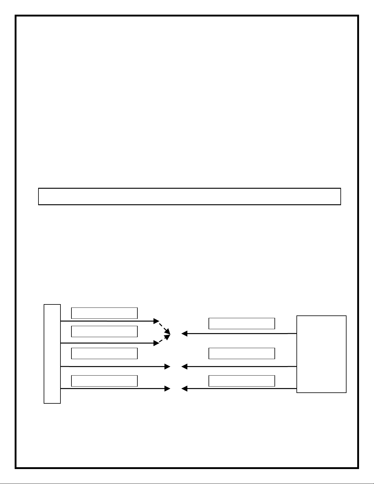
240 VOLT MAIN WALL SWITCH
X
–
WIRING DIAGRAM
WHITE - N
RED
L2
BLACK – L1
WALL
SWITCH
GROUND - G
FIREPLACE JUNCTION BO
WHITE –N
RED –L2
BLACK –L1
240 V
POWER
SUPPLY
(BREAKER
PANEL)
GROUND - G
8
Page 11

MAIN POWER WALL SWITCH WIRING
FOR 120 VOLT
NOTE:
This option should not be used with the remote control kit.
NOTE:
Before installing the unit have the following wires installed:
1. A 2 conductor wire with ground (3 wires total) from the power supply panel to the
main switch wall box.
2. A 2 conductor wire with ground (3 wires total) from the main switch wall box to the
junction box on the unit.
NOTE:
Use a single pole, single throw (on/off) wall switch that is rated for a minimum of 15 amps.
120 VOLT INSTALLATIONS
1. Locate the voltage selector switch inside the exhaust panel on the top right hand corner
of the unit. (see figure 2 on page 3)
2. Ensure that the switch is in the 120 volt position. (115 is printed on switch)
3. Loosen the screw securing the junction box cover and remove the cover.
4. Remove the knockouts (if necessary) or use the provided cable clamp.
5. Pull out the four wires marked L1, L2, N, and G. (black, red, white and green)
6. Connect the (black) L1 wire from the unit to the (black) L1 wire from the main power wall
switch using a wire connector (not supplied).
7. Connect the other end of the (black) L1 wire to the L1 terminal of the main power wall
switch.
8. Connect the (red) L2 wire from the unit and the (white) Neutral wire from the unit to the
(white) Neutral wire of the main power wall switch by using a wire connector (not
supplied).
9. Connect the other end of the (white) Neutral wire to the (white) Neutral wire from the
power supply panel by using a wire connector (not supplied).
10. Connect the (green) Ground wir e from the unit to the (green) Ground wire of the main
power wall switch by using a wire connector (not supplied).
11. Connect the (black) L1 wire from the power supply to the L1 terminal of the main power
wall switch.
12. Secure the 2 remaining (green) Ground wires with a ground screw in the main switch
wall box.
13. Ensure that all connections are tight.
14. Insert all the wiring of the main power wall switch into the main switch wall bo x.
15. Insert all the wiring back into the unit and secure with a cable clamp.
9
Page 12
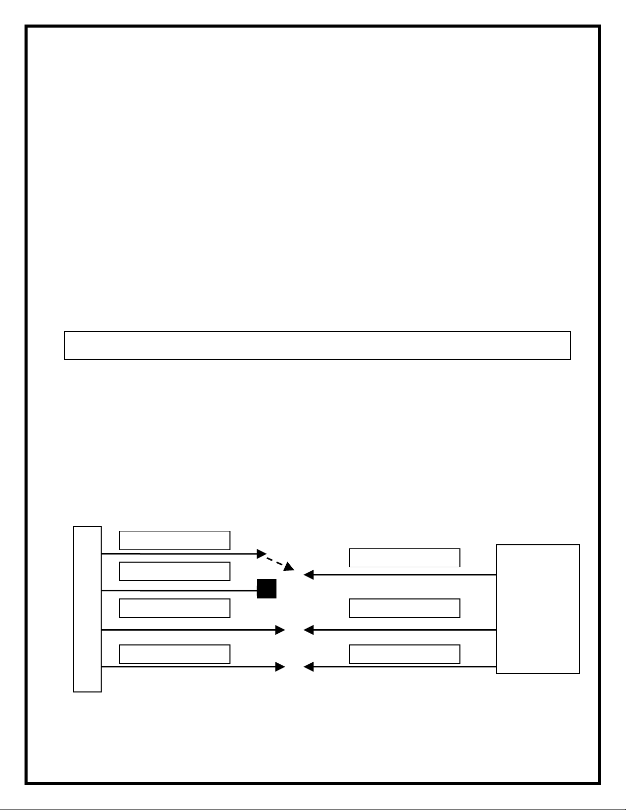
120 VOLT MAIN WALL SWITCH
X
–
WIRING DIAGRAM
FIREPLACE JUNCTION BO
WHITE - N
RED
BLACK – L1
GROUND - G
L2
WALL
SWITCH
WHITE –N
BLACK –L1
GROUND - G
120 V
POWER
SUPPLY
(BREAKER
PANEL)
10
Page 13

MAIN POWER WALL SWITCH WIRING
FOR 120 VOLT
NO HEAT INSTALLATION
NOTE:
This option should not be used with the remote control kit.
NOTE:
Before installing the unit have the following wires installed:
3. A 2 conductor wire with ground (3 wires total) from the power supply panel to the
main switch wall box.
4. A 2 conductor wire with ground (3 wires total) from the main switch wall box to the
junction box on the unit.
NOTE:
Use a single pole, single throw (on/off) wall switch that is rated for a minimum of 15 amps.
120 VOLT INSTALLATIONS
16. Locate the voltage selector switch inside the exhaust panel on the top right hand corner
of the unit. (see figure 2 on page 3)
17. Ensure that the switch is in the 120 volt position. (115 is printed on switch)
18. Loosen the screw securing the junction box cover and remove the cover.
19. Remove the knockouts (if necessary) or use the provided cable clamp.
20. Pull out the four wires marked L1, L2, N, and G. (black, red, white and green)
21. Connect the (black) L1 wire from the unit to the (black) L1 wire from the main power wall
switch using a wire connector (not supplied).
22. Connect the other end of the (black) L1 wire to the L1 terminal of the main power wall
switch.
23. Install a wire nut on the red L2 (wire nut not included).
24. Connect the (white) Neutral wire from the unit to the (white) Neutral wire of the main
power wall switch by using a wire connector (not supplied).
25. Connect the other end of the (white) Neutral wire to the (white) Neutral wire from the
power supply panel by using a wire connector (not supplied).
26. Connect the (green) Ground wir e from the unit to the (green) Ground wire of the main
power wall switch by using a wire connector (not supplied).
27. Connect the (black) L1 wire from the power supply to the L1 terminal of the main power
wall switch.
28. Secure the 2 remaining (green) Ground wires with a ground screw in the main switch
wall box.
29. Ensure that all connections are tight.
30. Insert all the wiring of the main power wall switch into the main switch wall bo x.
31. Insert all the wiring back into the unit and secure with a cable clamp.
11
Page 14

120 VOLT MAIN WALL SWITCH
X
–
WIRING DIAGRAM
NO HEAT INSTALLATION
FIREPLACE JUNCTION BO
WHITE - N
RED
BLACK – L1
GROUND - G
L2
Wire Nut
WALL
SWITCH
WHITE –N
BLACK –L1
GROUND - G
120 V
POWER
SUPPLY
(BREAKER
PANEL)
12
Page 15

SECTION E: HEATER WALL SWITCH AND WALL THERMOSTAT
WIRING OPTIONS
HEATER WALL SWITCH WIRING
FOR 120/240 VOLT
NOTE:
Before installing the unit complete the following:
1. Install main power connection with appropriate voltage as per Section C or
Section D.
2. Install a 2 conductor wire with ground (3 wires total) from the heater switch wall box
to the junction box on the unit.
NOTE:
Use a heater wall switch (on/off) that is rated for a minimum of 15 amps.
120 / 240 VOLT INSTALLATIONS
1. Loosen the screw securing the junction box cover and remove the cover.
2. Remove the knockouts (if necessary) or use the provided cable clamp.
3. Pull out the three wires marked 1, 2, and G. (red, red, and green)
4. Remove the wire connector and separate the wires marked 1 and 2.
5. Connect the (red) 1 wire from the unit to the (black) L1 wire from the heater wall switch
by using a wire connector (not supplied).
6. Connect the other end of (black) L1 wire from the heater wall switch to the L1 terminal
of the heater wall switch.
7. Connect the (red) 2 wire from the unit to the (white) Neutral wire from the heater wall
switch using a wire connector (not supplied).
8. Connect the other end of the (white) Neutral wire from the heater wall switch to the L2
terminal of the heater wall switch.
9. Connect the (green) Ground wire from the unit to the (green) Ground wire from the
heater wall switch using a wire connector (not supplied).
10. Secure the one remaining (green) Ground wire with a ground screw in the heater switch
wall box.
11. Ensure that all connections are tight.
12. Insert all the wiring of the heater wall switch into the heater switch wall box.
13. Insert all the wiring back into the unit and secure with a cable clamp.
13
Page 16

HEATER WALL SWITCH WIRING
DIAGRAM FOR 120/240 VOLT
(SEE SECTION C OR SECTION D FOR MAIN POWER CONNECTION)
FIREPLACE JUNCTION BOX
RED –2
RED –1
GROUND - G
WALL
SWITCH
14
Page 17

WALL MOUNTED THERMOSTAT WIRING
FOR 120/240 VOLT
NOTE:
Before installing the unit complete the following:
1. Install main power connection with appropriate voltage as per Section C or
Section D.
2. Install a 2 conductor wire with ground (3 wires total) from the thermostat wall box to the
junction box on the unit.
NOTE:
Wiring of the thermostat must be completed prior to installing the unit.
NOTE:
The following installation instructions are for a single pole thermostat.
120 / 240VOLT INSTALLATIONS
1. Loosen the screw securing the junction box and remove the cover.
2. Remove the knockouts (if necessary) or use the provided cable clamp.
3. Pull out the three wires marked 1, 2, and G. (red, red, and green).
4. Remove the wire connector and separate the wires marked 1 & 2.
5. Connect the (red) 1 wire from the unit to the white (neutral) wire from the wall
thermostat box by using a wire connector. (not supplied)
6. Connect the other end of the white (neutral) wire from the thermostat wall box to the red
wire from the wall thermostat.
7. Connect the (red) 2 wire from the unit to the black wire from the thermostat wall box by
using a wire connector. (not supplied)
8. Connect the other end of the black wire from the thermostat wall box to the black wire
from the wall thermostat.
9. Connect the green (ground) wire from the unit to the green (ground) wire from the
thermostat wall box by using a wire connector. (not supplied)
10. Connect the other end of the green (ground) wire to the thermostat wall box ground
screw.
11. Ensure that all connections are tight.
12. Insert all the wiring of the wall mounted thermostat into the wall box.
13. Insert all the wiring back into the unit and secure with a cable clamp.
15
Page 18

WALL MOUNTED THERMOSTAT WIRING
DIAGRAM FOR 120/240 VOLT
(SEE SECTION C OR SECTION D FOR MAIN POWER CONNECTION)
FIREPLACE JUNCTION BOX
RED –2
RED –1
GROUND - G
THERMOSTAT
CONNECT
GROUND TO
WALL BOX
WALL
16
Page 19

FLAME OVERRIDE SWITCH WIRING
FOR 120/240 VOLT
NOT AVAILABLE WITH NO HEAT INSTALLATION
NOTE:
The fireplace can be wired to have a wall switch operate the heater independent of the flame
NOTE:
Before installing the unit complete the following:
1. Install main power connection with appropriate voltage as per Section C or
Section D.
2. Install a 2 conductor wire with ground (3 wires total) from the flame override switch wall
box to the junction box on the unit.
NOTE:
Use a wall switch (on/off) that is rated for a minimum of 15 amps.
120 / 240 VOLT INSTALLATIONS
1. Loosen the screw securing the junction box cover and remove the cover.
2. Remove the knockouts (if necessary) or use the provided cable clamp.
3. Pull out the three wires marked 3, 4, and G. (blue, blue, and green)
4. Remove the wire connector and separate the wires marked 3 and 4.
5. Connect the (blue) 3 wire from the unit to the (black) L1 wire from the flame override
wall switch by using a wire connector (not supplied).
6. Connect the other end of the (black) L1 wire from the flame override wall switch to
the L1 terminal of the flame override wall switch.
7. Connect the (blue) 4 wire from the unit to the (white) Neutral wire from the flame
override wall switch using a wire connector (not supplied).
8. Connect the other end of the (white) Neutral wire from the flame override wall switch
to the L2 terminal of the flame override wall switch.
9. Connect the (green) Ground wire from the unit to the (green) Ground wire from the
flame override wall switch using a wire connector (not supplied).
10. Secure the one remaining (green) Gr ound wire with a ground screw in the flame
override switch wall box.
11. Ensure that all connections are tight.
12. Insert all the wiring of the heater wall switch into the heater switch wall box.
13. Insert all the wiring back into the unit and secure with a cable clamp.
.
17
Page 20

FLAME OVERRIDE WALL SWITCH WIRING
DIAGRAM FOR 120/240 VOLT
(SEE SECTION C OR SECTION D FOR MAIN POWER C0NNECTION)
NOT AVAILABLE WITH NO HEAT INSTALLATION
FIREPLACE JUNCTION BOX
BLUE –4
BLUE –3
GROUND - G
WALL
SWITCH
18
Page 21

WIRING DIAGRAM
LOWER SECTION
WHITE
FLICKER
MOTOR
BLUE (3)
BLACK
LOWER HARNESS
ORANGE FROM TOP
BROWN FROM TOP
CAPA-
CITOR
BROWN
WHITE
BLACK
RED (1)
RED FROM TOP
BYPASS HARNESS
MARR
WHITE (N)
BLUE (4)
MARR
BLACK
RED
RED
WHITE
BLUE
RED (2)
BLACK (L1)
WHITE
SWITCH
MAIN
4B5B1A
2A
1
2
RED (L2)
TWIST-TIE
HEATER SWITCH
G
WHITE (N)
RED (L2)
BLACK (L1)
GREEN
19
Page 22
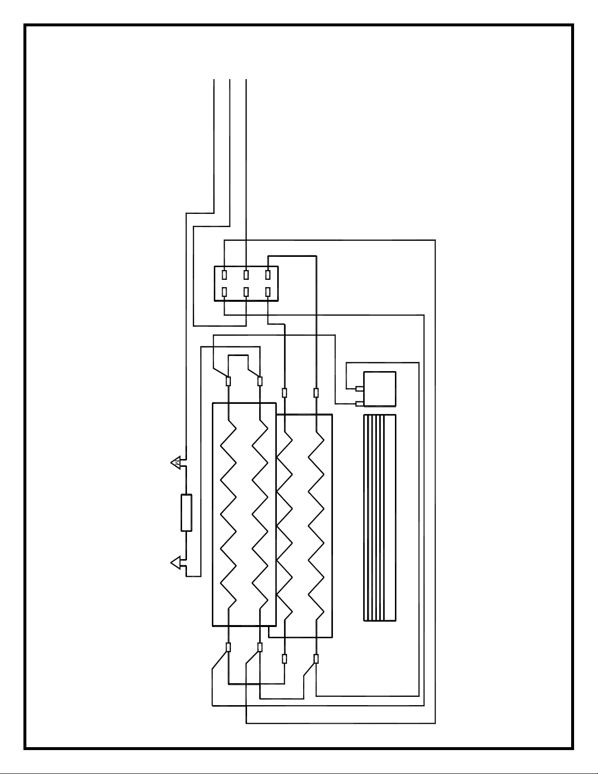
WIRING DIAGRAM
UPPER SECTION
CUT-OUT
M
RED (CUT-OUT LONG WIRE)
RED (CUT-OUT SHORT WIRE)
ORANGE
5
6
BLK
ELEMENT #2
YLW
BROWN
BLK
3
1
4
2
YLW
YLW
BLK
BLK
BLK
BLK
ELEMENT #1
BLW.
MOTOR
BLOWER WHEEL
20
Page 23

WIRING SCHEMATIC
21
Page 24

Approved for use in the United States and Canada
1-888-DIMPLEX
1-888-346-7539
1367 Industrial Road
Cambridge, Ontario
Canada, N1R 7G8
 Loading...