

Page 1

ContactDetails
Pleasenotethatsomeofthecontactdetailson
thisPDFdocumentmaynotbecurrent.
Pleaseusethefollowingdetailsifyouneedto
contactus:
Telephone:08448793588
Email:customer.services@gdcgroup.co.uk
Thecustomersupportsectionofourwebsitealsofeaturesawide
rangeofinformationwhichmaybeofusetoyouandisavailable
24hoursaday.Itincludes:
• Operatingandinstallationinstructions
• Easy‘Howtouse’guidesforstorageheaters
• Serviceandrepairs
• Where
tobuyourproducts
• Literaturedownloads
• Heatingrequirementcalculator
Visit‐www.dimplex.co.uk/support
A division of GDC Group Ltd
Millbrook House Grange Drive Hedge End Southampton SO30 2DF
www.dimplex.co.uk
Registered No: 1313016 England
VAT GB 287 1315 50004
EEE Producer Registration Number –
WEE/GE0057TS
Paper from sustainable sources
Page 2

SERVICE POLICY / GUARANTEE
Shower User Guide
Before telephoning the Dimplex Customer Service Department you should ensure
that you have the model number, power rating, serial number and date of purchase.
The Dimplex Customer Service Department will be able to inform you whether the
fault can be rectied by the provision of a replacement part or an on site visit by a
Qualied Service Engineer.
If a service call is booked, you or a representative must be present during the
Engineers visit.
A charge will be made where a call under the terms of the guarantee has been
booked and a failure was not product related, or an engineer arrives and is not able
to gain access.
If the product is no longer covered by the Guarantee, a charge will be made for the
site visit and for any parts supplied.
SERVICE POLICY
5
4
3
2
1
In the event of you needing to contact the Dimplex Customer Service Department, the following
procedure should be followed:
Customer Service Department 9.00am - 5.00pm Monday to Friday
Tel: 0845 600 5111 Fax: 01489 773053
GUARANTEE
Dimplex UK Limited guarantee this Dimplex product for a period of two years, from date of
purchase, against mechanical and electrical defects arising from faulty materials or from poor
workmanship, providing the product has been installed by a competent person in accordance
with the tting instructions.
Dimplex UK Limited undertake to repair or replace, at their discretion, without charge, provided
the product has been properly maintained and operated in accordance with the operating
instructions. Any component found to be defective during this period, as the result of misuse or
damage, or the effects of scaling, will not be covered by this guarantee (with the exception of ‘si’
(Scalemaster’) models which are guaranteed against the effects of scaling).
This product must not be modied, repaired or taken apart except by a person authorised by
Dimplex UK Limited.
This Guarantee is only valid within the United Kingdom and does not cover product used
commercially. This Guarantee does not affect your statutory rights.
Dimplex UK Limited Millbrook House, Grange Drive, Hedge End, Southampton SO30 2DF
Telephone: 0845 600 5111 - Fax: 0845 773050.
AX2 12pg booklet printers spread2-3 2-3 13/8/07 2:16:11 pm
Page 3
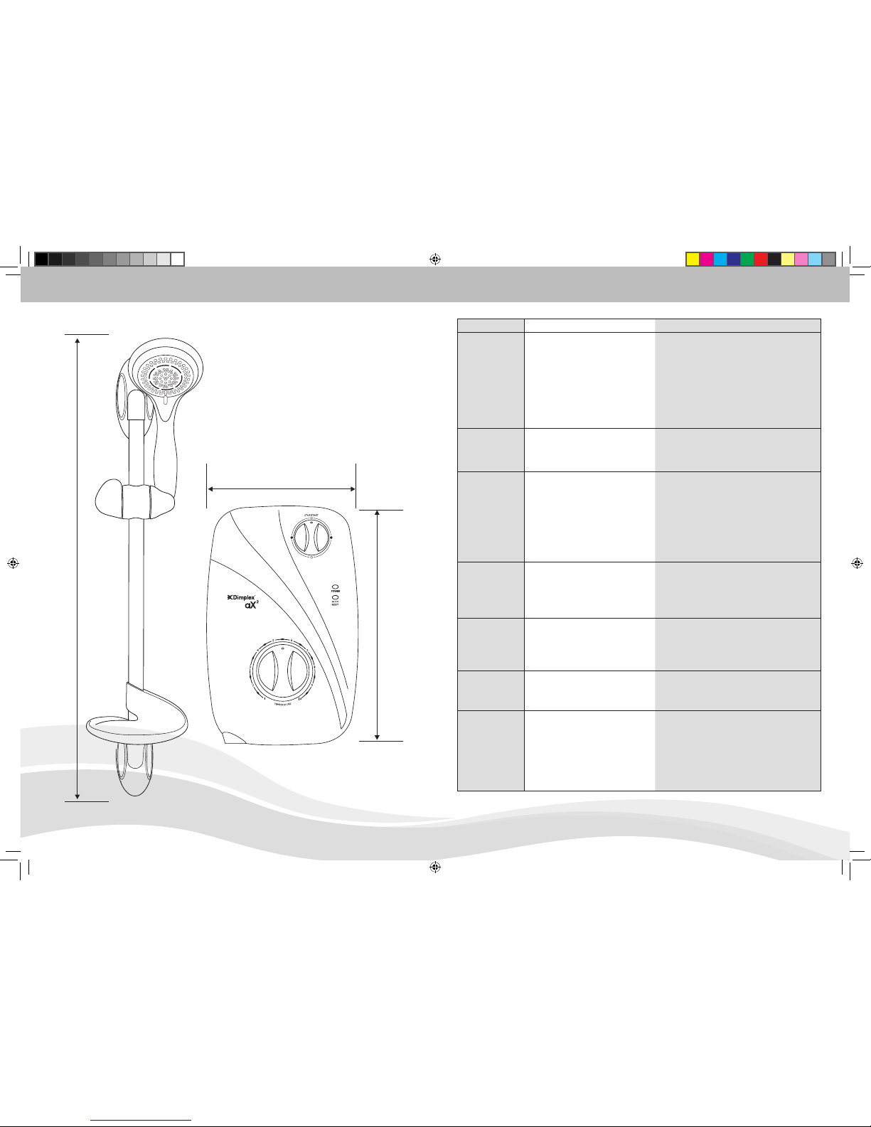
DIMENSIONS
2
690 mm
218 mm
339 mm
TROUBLESHOOTING GUIDE
11
SYMPTOM POSSIBLE CAUSE ACTION
No hot water. Power setting is at Cold. Turn power knob to a heat setting.
Low Water Pressure. The water supply has dropped below the minimum
operating pressure. Switch off other cold water
devices and retry.
The thermal cut-out has operated. Turn the Power knob to cold. Switch off the
shower. Clean the shower head, and restart the
shower. Select a heat setting. If no hot water is
produced call the Dlmplex Service Centre.
Power indicator
is not lit.
The power setting is on cold. Turn the power setting to a heat setting and the
indicator should light.
Water pressure below minimum
required.
Check If water mains stop valve is fully open.
Water too hot. Not enough water owing through the
shower.
Increase ow rate via temperature control.
Blockage in supply. Blocked spray head - clean or replace blocked
spray plate in spray head.
Check If stop valves are fully open. Check for
blockage in inlet lter.
Increase in ambient water temperature. Re-adjust ow rate to give increased ow.
Select ‘Low’ power.
Water too cool
or cold.
Water ow too high. Reduce ow rate via temperature control.
Water pressure below minimum
required (See rating label).
Check water supply.
Reduction in ambient water
temperature.
Select ‘High’ power.
Water ow is poor. Shower head is blocked. Clean the showerhead. Ensure showerhead is as
specied by manufacturer.
The temperature control knob is set at
its hottest setting.
Increase the power setting by turning the power
knob to hot and increase the ow using the
temperature control knob.
Water continues
to drip from the
handset when
switched off.
Water is draining from the shower unit,
after use.
This is normal, no action required. Should water
continue to drip after a few minutes contact’
Dimplex Service Centre.
Pressure relief
device has
operated (water
ejecting from
Pressure Relief
tube).
Blocked spray head. Remove handset and run water through the
shower and hose to remove any dirt that may be
trapped In the system. Clean or, if possible, replace
the spray plate in the spray head and then t a new
Pressure Relief Device.
Twisted/blocked exible shower hose. Check the hose is not restricted anywhere along its
length. Replace the hose if necessary and t a new
Pressure Relief Device.
AX2 12pg booklet printers spread4-5 4-5 13/8/07 2:16:14 pm
Page 4

PACKING CONTENTS / GENERAL ADVICE TO SHOWER UNIT USERS
SECTION 2
General advice to
shower unit users
SECTION 1
Packing contents
6. All plumbing connections must be
completed before making the electrical
connections.
7. The outlet of your shower acts as a vent
and must NOT be connected to any form
of tap or tting not recommended by
Dimplex Showers Ltd.
8. Always switch off at the isolating switch
when not in use.
3
The following points will help you to
understand how your Dimplex shower unit
operates.
The ow rate of water passing through the
shower unit determines the water temperature.
The lower the ow the warmer the water, the
higher the ow the cooler the water.
The temperature produced by the shower
unit will vary between seasons on any one
setting of the temperature control. This is due
to variance in the temperature of the water
supply, which becomes cooler in winter than
summer.
The stabiliser valve maintains an almost
constant shower temperature during mains
water pressure changes.
If changes in temperature are experienced in
normal use, it is likely to be caused by water
pressure falling below the minimum level. Falls
in water pressure may be due to water being
drawn off at other points within the building.
The shower head must be cleaned regularly to
remove scale and debris. If the water becomes
hot and you are unable to obtain cooler water,
check the shower head for blockage.
l Shower Unit
l Shower Head
l Flexible Hose
l Slider Rail Tube
l Slider Rail Brackets
l Slider Rail Showerhead Holder
l Soap Dish
l Screw Pack
IMPORTANT:
1. Shower installation must be carried out by a
suitably qualied person and conform with
IEE Regulations and National Water Council
bylaws.
2. This shower unit is designed to be
connected to a 15mm cold water mains
supply. Do not connect to a tank supply
unless a suitable booster pump is
tted.
3. The minimum recommended running
water pressure to which the shower heater
may be connected is 15 lb/sq in (1 Bar).
Running pressure at 8 litres per minute. The
maximum static pressure recommended is
150 lb/sq in (10 Bar).
4. The shower unit must not be tted where
it may be exposed to frost, for example
in an outdoor shower area. The shower
must not be used if suspected of being
frozen. Frost damage is not covered by the
guarantee.
5.
Plumbers jointing compound must
not be used. In instances of difcult joints
use P.T.F.E. Tape. The use of compound
invalidates the guarantee.
OPERATING FEATURES / CLEANING INSTRUCTIONS
10
SECTION 11
Operating features
Power Neon Indicator
The ‘Power’ neon indicator will be illuminated
when the shower unit is switched on and
water is owing on the heat settings. The light
will not come on when the shower unit is on
the cold setting.
Auto Reset Neon Indicator
The Auto Reset Neon Indicator will be
illuminated during normal operation if an
overheat temperature is sensed, power to the
element will be cut off, water will continue to
ow until the unit has cooled sufciently. Power
to the elements will be automatically restored.
If the Auto Reset Neon Indicator persistently
functions, ensure that the shower head is free
from scale and debris which will increase the
ow of water through the unit.
SECTION 12
Shower head cleaning instructions
IN SHOWER MAINTENANCE
To break away scale
deposits on a daily basis
simply rub your thumb over
the rubber nipples whilst the
shower is running.
The shower head should be cleaned
periodically to remove limescale or debris
which will reduce the performance of the
shower. The frequency of cleaning will vary
according to local water quality. In hard water
areas cleaning will be needed more often
than in soft water areas. A liquid non-abrasive
bathroom cleaner may be used on external
surfaces of the handset.
AX2 12pg booklet printers spread6-7 6-7 13/8/07 2:16:15 pm
Page 5

double pole heater switch wall mounted in
accordance with local authority regulations
seperate permanently
connected supply
from consumer unit
Dimplex electric
water heater
cold
water
mains
supply
isolating
stop tap
SECTION 3
General layout of a
shower installation
INSTALLATION
SECTION 4
Installation
Position your shower unit on the wall away
from the direct spray of the shower and at
about the same height as the shower head
position.
The shower unit should be positioned so that
the shower head cannot be immersed in the
bath or shower tray when hanging down.
Shower unit can be mounted
either side of riser rail
Outline of bath
or shower tray
Spillover
level
Spillover
level
Mains cold water supply
(either top, bottom
or rear entry)
Height of sprayhead
and shower to suit
user’s requirements
Soap dish
A TYPICAL INSTANTANEOUS ELECTRIC SHOWER
INSTALLATION
4
Plan your own installation carefully. Check on
the nearest and most readily accessible rising
mains water supply, this may be beneath the
bath or in the loft, where it feeds the cold
water storage tank. Use only the cold rising
water main supply.
Do not connect the shower unit to the
down service from the tank.
Avoid connecting the shower unit, if possible,
were it will be affected by water drawn off by
other appliances, e.g. From the mains feed to
the W.C., This may cause a drop in pressure
too low for the shower unit to work correctly.
An isolating valve must be tted into the water
supply for servicing purposes.
Remove the two screws securing the shower
unit cover and remove the cover complete with
the control knobs.
Place the shower unit on the wall and mark the
location of the xing screws through the back
plate.
Carefully drill the holes as marked using a
sharp 5.5mm masonry drill.
Fix the shower unit to the wall using the plugs
and screws provided, do not fully tighten at
this stage.
OPERATING INSTRUCTIONS
‘High’ setting (Solid Red Symbol):
This is the full power setting.
Temperature adjustment is via the
bottom temperature control.
4. Wait a few seconds for the warmer water to
reach the handset.
5. If necessary turn bottom
‘Temperature’
control knob slowly to obtain desired
showering temperature. Again, waiting
a few seconds after each adjustment in
temperature to reach the handset.
Note:
To adjust the shower temperature.
The water temperature is altered by
increasing or decreasing the ow rate
of water through the shower unit via the
temperature control.
To increase the shower temperature
Turn the temperature control knob
clockwise, this will decrease the ow
of water and increase the shower
temperature.
To decrease the shower
temperature
Turn the temperature control knob
anti-clockwise, this will increase the
ow of water and decrease the shower
temperature.
6. Turn the top power selector knob to the
STOP/START position (Outline Grey
Symbol) to stop the ow.
7. A small amount of water will be retained
in the shower head after the shower has
been turned off. This may drain over a few
minutes.
8. Switch off pull-cord or wall mounted switch.
9
COOLER WARMER
COLD
LOW
HIGH
AX2 12pg booklet printers spread8-9 8-9 13/8/07 2:16:18 pm
Page 6

IMPORTANT
To comply with National Water Council bylaws
a double check valve must be tted with all
exible shower accessories where it is possible
that the shower head may come into contact
with used water i.e. in the bath or shower tray.
SECTION 5
Plumming connection
Plumbing the shower unit must precede
wiring.
Turn off the water supply at the isolating stop
tap.
Having determined the direction of the inlet
water supply: Top (falling), Bottom (rising),
or Back inlet. It is necessary to remove the
appropriate plastic cross section from the back
plate, before commencing with the installation
(See diagrams Fig 1 & Fig 2).
PLUMMING CONNECTION
5
The back plate is tted with removable inserts
for Top (falling) and Bottom (rising) inlet mains
water pipework to the shower unit.
We have incorporated into the bottom righthand side of the back plate an easy removable
trim section, to allow easy access when
connecting the water supply.
(Please Note! Remember to replace this trim
section before retting the cover).
Remove this plastic
cross-section when using
the ‘REAR’ or ‘TOP’ entry
point for plumming
Remove this plastic
cross-section when using
the ‘BOTTOM’ entry point
for plumming
Connect the mains water supply to the inlet
of the shower unit using a 15mm copper or
stainless pipe with a 15mm compression
elbow or 15mmm push-t elbow. Do not
use excessive force when making the
connection to the unit.
IMPORTANT
Before turning on the water supply to the
shower unit the water supply pipe should be
ushed out to remove debris. This can be
achieved by connecting the exible hose to the
15mm compression elbow and turning on the
mains water supply long enough to clear the
debris.
After ushing the pipework ensure that the
shower unit is positioned squarely on the wall
and tighten the screws. Tighten all plumbing
connections and check the pipework for leaks.
Fig 1 Fig 2
The temperature at the shower head will
rise further - this shows that the full power
setting is operating correctly.
10. Turn the bottom temperature control
knob clockwise for hotter water and
anti-clockwise for cooler water. Allow a
few seconds between selections - for the
temperature change to reach the shower
head.
NOTE. When the temperature is changed
the ow rate alters.
11. Turn the top power selector knob to the
STOP/START position (Outline Grey
Symbol) to stop the ow.
COMMISSIONING THE SHOWER / OPERATING INSTRUCTIONS
SECTION 10
Operating the shower
1. Switch on pull-cord or wall mounted switch.
The ‘Power’ neon will illuminate indicating
the switch is on.
2. Turn the top power selector knob to the
COLD (Solid Blue Symbol) setting, this
action will also activate the internal solenoid
valve turning the water on.
3. Select your power setting using the top
control. The shower has three positions
‘Cold’, ‘Low’ power and ‘High’ power.
‘Cold’ setting (Solid Blue Symbol):
Adjustment of the ow control on this
setting will only alter the ow of water not
the water temperature.
‘Low’ setting (Outline Red Symbol):
This is the low power setting for
economy during warmer months
or when a cool shower is required.
Temperature adjustment is via the
bottom temperature control.
8
SECTION 9
Commissioning the shower
1. Make sure that the top power selector
knob is in the STOP/START position
(Outline Grey Symbol) and that the
electrical supply has been isolated at the
double pole isolating switch.
2. Turn the bottom temperature control knob
anti-clockwise to the full cold position.
3. Ensuring the water supply is fully on at the
mains stop cock and isolating service valve
(if tted), check that water is not leaking
from the bottom of the case.
4. Switch on the electrical supply at the
double pole switch. The ‘Power’ neon
indicator will light.
5. Turn the top power selector knob to
the COLD (Solid Blue Symbol) setting,
this action will also activate the internal
solenoid valve turning the water On.
Check that water ows freely from the
shower within a few seconds. The water
from the shower head will be at full force
and at a cool temperature.
6. Rotate the bottom temperature control
knob slowly clockwise fully. This will
gradually reduce the ow with the water
temperature remaining cool.
7. Return the knob anti-clockwise to
maximum ow.
8. Now turn the top power selector knob to
the ‘Low’ setting (Outline Red Symbol).
Allow a few seconds for the warmer
temperature to reach the shower head
- this shows that the ‘Low’ power setting
is operating correctly.
9. Now turn the top power selector knob
to the ‘High’ setting (Solid Red Symbol).
AX2 12pg booklet printers spread10-11 10-11 13/8/07 2:16:19 pm
Page 7

7
FITTING INSTRUCTIONS
TIPS
A piece of insulating or masking tape applied
to the wall before marking out the xing
holes will help stop the drill from wandering,
particularly on tiled surfaces. When working
near a basin or bath, insert the plug in the
waste tting so that small parts cannot be lost.
Take care not to drop accessories or tools into
basin or bath.
CAUTION
Check there are no hidden cables or pipes
before drilling holes for wall plugs. Exercise
great care when using power tools near water.
The use of a residual current device (RCD) is
recommended.
SECTION 8
Riser rail & soap dish
tting instructions
6
A
A
B
B
5
7
excess material from the
plain end of the rail.
5. The three components
that comprise the
Handset Height Adjuster
assembly are produced
with alphabetical ‘A’s and
‘B’s moulded into the
end section of each part.
Simply just match the letter
identication of each part
with the central piece i.e.
‘A’ to ‘A’ and ‘B’ to ‘B’ for
correct assembly.
6. With the shower head
height adjuster lever set a
3 o’clock and the shower
head holder in the upright
position, slide the assembly
onto the rail. Tighten to the
rail by turning the lever.
7. To lock the Handset Height
Adjuster at your chosen
position on the rail. Turn the
lever up right. This action
is also used for holding the
shower head at the angle
required.
8. Re-assemble the rail and
screw the upper mounting
bracket in place.
9. Slide the end cap onto the
mounting brackets.
10. Snap the soap dish onto
the rail below the holder
assembly.
11. Slide soap dish down the
rail to required position.
12. Firmly attach exible hose
to the shower head making
sure sealing washer is in
place. NOTE: the adjustable
slider grips the conical end
of the hose, not the handle
of the shower head.
4
8
9
10
11
12
2
1
1. Establish position for the
riser rail, and mark the wall
for the lower mounting
bracket.Make allowances
for the tallest person likely
to use the shower regularly.
2. Use a No 10/5.5mm
masonry drill to make a
hole 35mm deep, and
t the wall plug. (NB
some wall constructions
may require the use of
alternative types of wall
xings). Screw the lower
bracket base to the wall.
3. Locate the crimped end of
the riser rail (Fig. 4) into the
mounting bracket, then t
the upper bracket. Ensure
the rail is vertical, then mark
the wall for the xing.
4. The crimped end of the riser
rail. NOTE: If it is necessary
to shorten the rail, use a
junior hacksaw to cut the
3
Maintenance: Clean regularly with a non-
abrasive liquid bathroom cleaner.
6
ELECTRICAL CONNECTION / FITTING INSTRUCTIONS
The incoming cable should be hidden.
Connect the live cable to the terminal
marked L.
Connect the neutral cable to the terminal
marked N.
Connect the earth cable to the terminal
marked E on the back plate.
IMPORTANT
Ensure that the terminal block screws are
fully tightened and that no cable insulation is
trapped under screws.
Ensure the cable clamp is used to secure the
cable.
The earth continuity conductor of the electrical
installation must be effectively connected to all
SECTION 7
Fitting the cover into position
NOTE: It is necessary to align the ‘D’ at on
the reverse side of the Power Selector and
Temperature knobs with their opposite control
spindles before the cover is located.
Secure the cover with the two xing screws
provided.
IMPORTANT: Turn the ow control knob
anti clockwise until the valve is fully open
before switching on the unit. This will
ensure a fast ll up of the unit when the
shower is rst switched on.
Switch on the power to the shower unit at the
consumer unit and the double pole switch. At
this stage the power selector knob should be
on the STOP/START position (Outline Grey
Symbol).
Remove the shower head from the exible
hose and point to waste.
Turn the top power selector knob to the COLD
(Solid Blue Symbol) setting, this action will
also activate the internal solenoid valve turning
the water on. Let the water ow through the
shower unit to release any air which may be in
the system and ll the shower unit with water.
IMPORTANT: The shower unit must be full
of water before heat settings are used.
Turn the top power selector knob to the
STOP/START position (Outline Grey Symbol).
Re-t the shower head to the exible hose.
Your shower is now ready to use. We
recommend that you allow your shower
to reach a stable temperature before you
commence showering.
SECTION 6
Electrical connection
Warning! This appliance must be earthed
The shower unit must be permanently
connected to the electricity supply, direct from
the consumer unit via a double pole linked
switch with a minimum contact gap of 3mm.
The switch must be readily accessible and
clearly identiable and out of reach of a person
using a xed bath or shower tray, unless the
switch is cord operated. The wiring must be
connected to the switch without the use of a
plug or socket outlet.
The cable size required is determined by the kW
rating of the shower and the distance between
the shower and the consumer unit. The table
below will help you choose the correct cable
for your installation, but it will depend upon the
precise circumstances of the installation. If you
are in any doubt consult an electrician.
KW
RATING
NOMINAL
AT 240v
MIN. RATING
OF ISOLATING
SWITCH
FUSE
RATING
MAX CABLE
RUN
6mm 10m
7.0 29.10 amps 30 amps 30 amps 29m 48m
7.5 31.25 amps 40 amps 40 amps 27m 44m
8.0 33.33 amps 40 amps 40 amps 25m 42m
8.5 35.41amps 40 amps 40 amps 23m 38m
9.5 39.58 amps 40 amps 40 amps 21m 32m
10.5 43.75 amps 45 amps 45 amps 18m 30m
exposed metal parts of other appliances and
services in the room in which the shower unit is
installed to conrm with IEE regulations.
AX2 12pg booklet printers spread12-13 12-13 13/8/07 2:16:23 pm
 Loading...