

Page 1
INSTALLATION AND SERVICING INSTRUCTIONS
BE GIVEN TO THE USER
TO
Ref. : 1871184 - 0106157
Cast iron installed
electric boiler
Made in France
Model MA
• Electronic regulation
• 1 heating circuit
Model : ASCMA 12
Informations given in this manual are not contractuals, may therefore change technical caractéristics or components without notice
Ascari - 12kW -page 1 -
Page 2

CONTENTS
1 - Generalities............................................................................................................... p. 04
1.1 - Introduction ................................................................................................................................. p. 03
1.2 - Important information................................................................................................................... p. 03
1.3 - Description.................................................................................................................................. p. 04
1.4 - Dimensions - Hydraulic Connections........................................................................................... p. 06
1.5 - Datas.......................................................................................................................................... p. 07
2 - Installation ................................................................................................................. p. 08
2.1 - Location...................................................................................................................................... p. 08
2.2 - Fitting the boiler .......................................................................................................................... p. 08
2.3 - Hydraulic connections................................................................................................................. p. 09
2.4 - Mixing valve ................................................................................................................................ p. 09
2.5 - Expansion vessel - Pressure safety relief .................................................................................... p. 09
2.6 - Frost protection........................................................................................................................... p. 09
2.7 - Bleeding...................................................................................................................................... p. 09
2.8 - Plumbing .................................................................................................................................... p. 10
2.9 - Filling loop .................................................................................................................................. p. 10
3 - Electric connections .................................................................................................. p. 11
3.1 - Electric flow rate, number and cross-section of power connectors,
fuse protection ............................................................................................................................ p. 12
3.2 - Power terminal ............................................................................................................................ p. 14
3.3 - Connection to mains depending on power supply ........................................................................ p. 15
3.4 - Regulation circuit ........................................................................................................................ p. 16
3.5 - Control accessories wiring .......................................................................................................... p. 17
3.6 - Wiring diagrams.......................................................................................................................... p. 18
3.7 - Heating elements connections .................................................................................................... p. 20
4 - Basic hydraulic patterns............................................................................................. p. 21
4.1 - Direct heating circuit ................................................................................................................... p. 21
5 - 3 speed water pump.................................................................................................. p. 22
6 - Electronic 2 circuits regulation ................................................................................... p. 23
6.1 - Généralities ................................................................................................................................ p. 23
6.2 - Control command pannel ............................................................................................................ p. 24
6.3 - Setting the regulation .................................................................................................................. p. 25
6.4 - Operating .................................................................................................................................... p. 27
6.5 - Counters ..................................................................................................................................... p. 29
6.6 - Failures display........................................................................................................................... p. 29
7 - Heating diagram........................................................................................................ p. 31
7.1 - Underfloor heating ....................................................................................................................... p. 31
7.2 - Radiators .................................................................................................................................... p. 31
7.3 - Specific heating diagram ............................................................................................................. p. 32
8 - Maintenance.............................................................................................................. p. 33
9 - Troubleshooting......................................................................................................... p. 33
Spare p arts ............................................................................................................... p. 34
Ascari - 12kW -page 2 -
Page 3

1 - GENERALITIES
Features
• Selectable Water Temperature
- radiators / Underfloor (21-80°C)
• 60°C or 100°C thermal cut-out suitable for underfloor heating or radiators
• Room thermostat operation
• Frost protection, 5°C minimum temperature
• Pump protection -once a day operation when system is off
• Pump overrun facility
• 4-stage stepped turn on/off
• Weekly alternative switch start-up for prolonged life
• Automatic water temperature variation for 50% on-off cycles (with room thermostat)
• Switch operation counter -monitors switch usage
• System pressure display
Water heating
It is recommended that the boiler be used for central heating purposes only and hot water be stored and
heated by a direct electric hot water cylinder. This allows hot water to be heated over night on an off-peak
tariff and reduces heat losses between the boiler and the cylinder.
1.1 - Introduction
The Dimplex Ascari boiler is an all electric domestic central heating boiler suitable for use on a 230V 52A
50Hz supply. The unit is easy to install and requires no flue, making it ideal for apartments or properties in
conversation areas.
The unit is supplied ready for operation as a 12kW 230V sigle phase boiler and will automatically modulate
down to 10, 8 and 6kW. The maximum output power may also be manually limited to operation at maximum
power levels of 10, 8, 6 or 4kW upon which the boiler will proportionnaly modulate to lower power levels.
Finished in a clean white case and with dimensions of 620mm height x 405mm width, the boiler is suitable for
installation in a kitchen area. With thermal cut out selectable at 60°C or 100°C the boiler is suitable for
standard wet radiators systems or underfloor heating.
There are no ventilation requirements associated with the operation of this boiler , however to maintain a dry
atmosphere a well ventilated room is recommended.
1.2 - Important information
• The information given in this booklet is a guide only. All installations must follow the current regulations for
this type of device and where no information or conflicting information is given in this guide to that of the
current regulations, the current regulations will apply .
• Disconnect the Electricity Supply before attempting to remove the cover of the boiler .
• The boiler weighs 38kg and requires two persons to lift and install the product. Please ensure all mounting
fixings and the wall onto which it is to be installaed are sufficiently strong to take the weight of the unit plus
its water contents.
Ascari - 12kW -page 3 -
Page 4
• The heating system must be installed by a competent person and to current regulations in force at the time.
• All wiring should conform to the regulations in force at the time. The appliance is approved to a protection
rating of IPX1. Therefore if the appliance is to be installed in a room containing a bath or a shower, any
electrical switch or control utilising mains electricity must be so situated that it cannot be touched by a
person using the bath or shower. Attention is drawn to the requirements of the current BS 7671 (I.E.E.
Wiring Regulations) and in Scotland the electrical provisions of the Building Regulations applicable in Scotland.
• Complete all plumbing work before connecting ther boiler to the electricity supply.
• this appliance must be earthed !
• The boiler should be permanently connected to the electricity supply , direct from a 63A fused supply on the
consumer unit via a double pole linked switch with minimum contact gap of 3mm. No other appliances
should be powered from this supply .
• The expansion vessel is pre-charged to 1 bar (0.1MPa). During the installation process and before operating
the boiler this should be checked using a suitable pressure gauge.
• A 3 bar (0.3MPa) pressure relief device is incorporated within the product, the cold system pressure should
not exceed 1.5bar (0.15MPa).
1.3 - Description
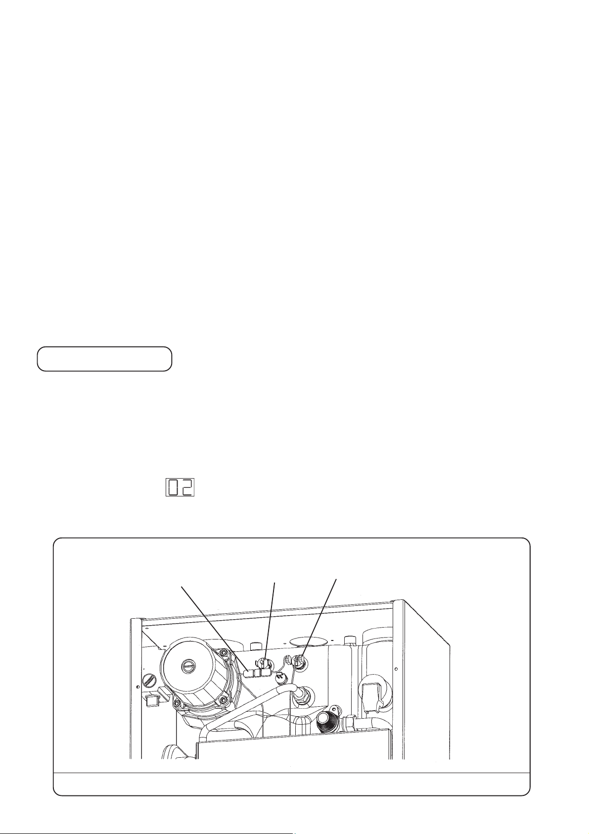
1.3.1 - Settings for low temperature systems (floor heating only)
ASCARI boiler is supplied ready for connection to a high temperature system ranging from 0 to 80 °C with
a high temperature safety limitator set at 100 °C (radiators or floor heating and Domestic Hot Water production).
For connection to a low temperature system ranging from 21 to 50 °C with a high temperature limitator set at
60 °C, adjust parapeter #
limitator.
The two safety limitators are located over the electric pannel (see Pic. 1 below).
Safety limitators with manual reset
Dual connector
(TCMA) to a 50°C or lower value (see § 6.3) and connect the 60 °C safety
60°C
100°C
Ex-work wiring for high temperature system with 100°C high temperature cut-out
Ascari - 12kW -page 4 -
Page 5
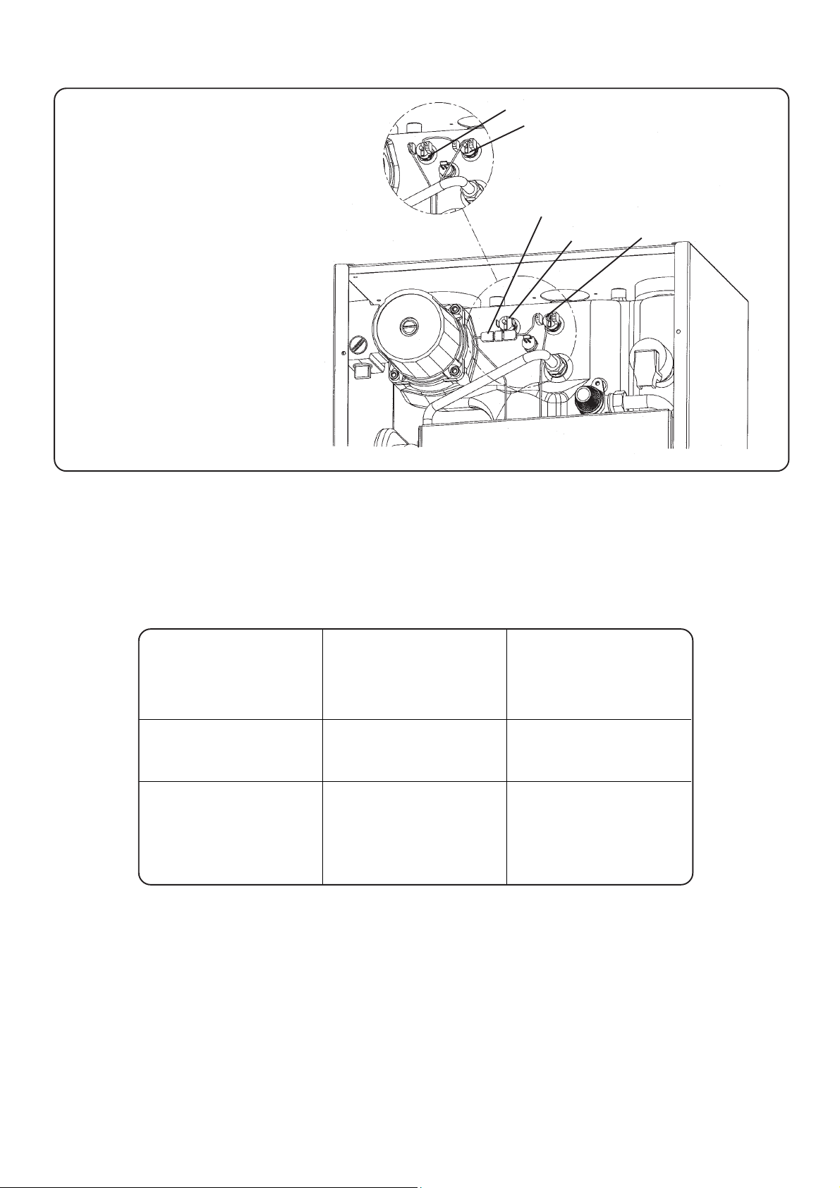
Electric connection of the 60°C temperature limitator for use with a low temperature system.
60°C
100°C
Dual connector
60°C
100°C
Disconnect the dual
connector and connect the
two female connectors to the
60°C safety limitator .
1.3.2 - Water temperatures settings summary
Parameter # 02
Heating system
Floor heating (ex-work
settings)
Radiators
or floor heating with
Domestic Hot Water
production (ex-work
settings)
Maximum boile r's
temperature (TCMA)
see § 6.3
21 - 50°C
22 - 80°C
Safety limitator AQS
60°C
permanent
100°c
permanent
Ascari - 12kW -page 5 -
Page 6
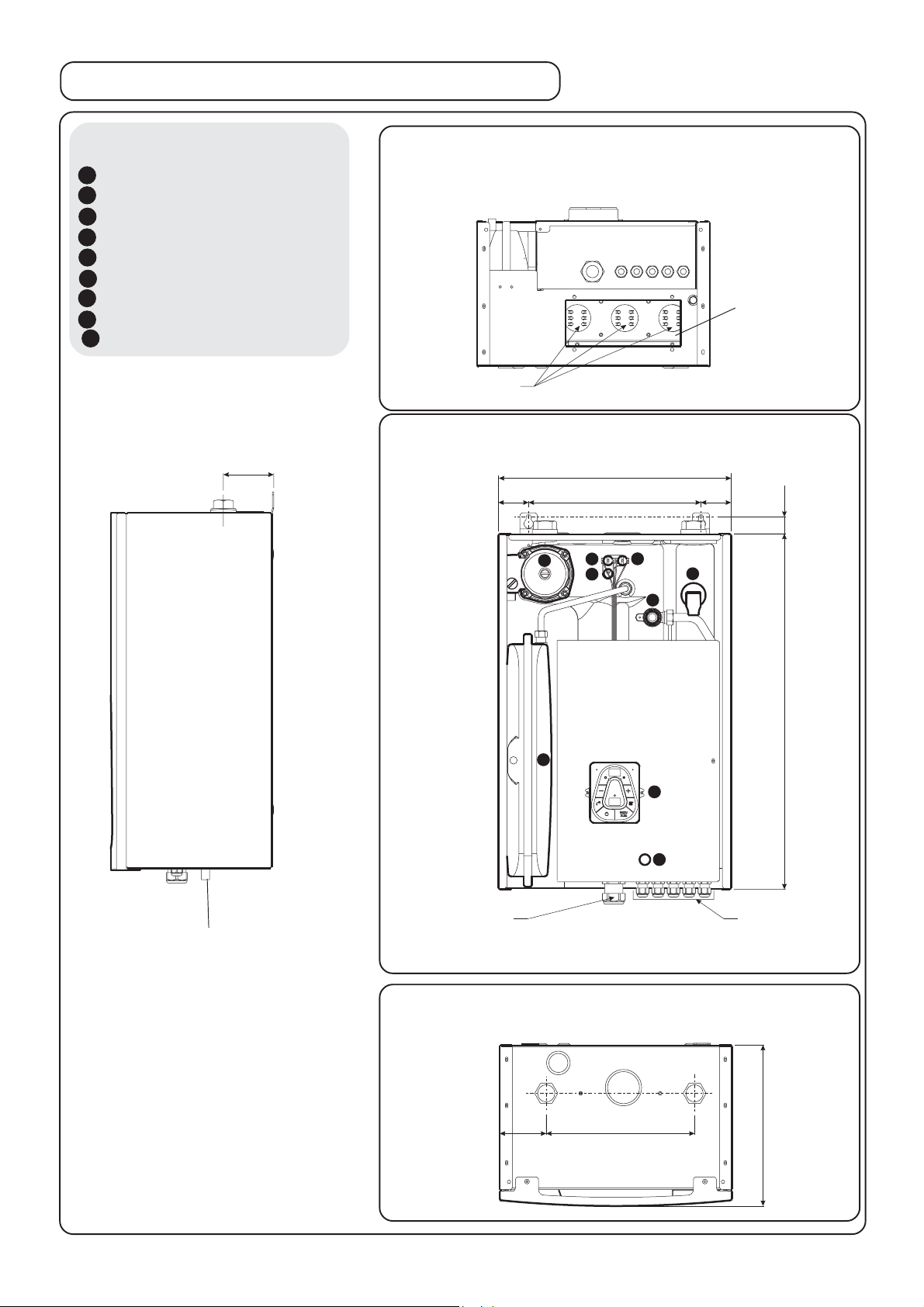
1.4 - Dimensions - Hydraulic connections
Decoding
1 - 3 speed pump
2 - 8 liters expansion vessel
3 - 3 bar safety relief bleeder
4 - La ck of water sensor
6 - 60°C safety limitator
7 - 100°C safety limitator
8 - Boiler's sensor
9 - Control pannel
11 - Fuse
Side view
87,5
(Trapdoor to access elements removed)
Heating elements
Bottom view
Front view
1
6
8
405
300
Elements fastener
29
7
4
3
619
2
9
11
Safety relief drain
Power wire entry
Accessories
connection entries
Ø15
Top view
DR
D = Heating outflow 1" female nut (26/34)
R = Heating backflow 1" female nut (26/34)
81
259
280
Ascari - 12kW -page 6 -
Page 7
1.5 - Datas
ASCARI
Designation
12 MA
230 V mono
Heat exchanger
Elements
Maximum output P1 (ex-work wiring)
Nbr of power stages
230 V mono 50Hz * power supply
230V tri 50Hz * power supply
Maximum output P1 adjustment * changing
heating elements wiring
Remote cut-out of one or two power stages
Water capacity 5 litres
2 heaters comprising 3 x 2kW incoloy elements
Cast iron
12 kW
4
YES
NO
P4 = 6kW
P3 = 8kW
P2 = 10 kW
6 kW
Expansion vessel
Water connections
Minimum pressure
Nominal pressure
Maximum pressure
Minimum temperature
Maximum operating temperature
Minimum water flow
Nominal water flow
Maximum water flow
Weight
Dimensions Width 405 mm
Height
80 °C (ex-work) adjustable to 50°C
8 litres
1" (26/34)
0,5 bar
2 bar
3,0 bar
21 °C
350
700
2400 l/h
38 Kg
620 mm
Security class
Power rate at 70°C
* : see § 3.3
Depth
Ascari - 12kW -page 7 -
280 mm
IPX1
3,40 kWh / 24 h
Page 8
2 - INSTALLATION REQUIREMENTS
2.1 - Location
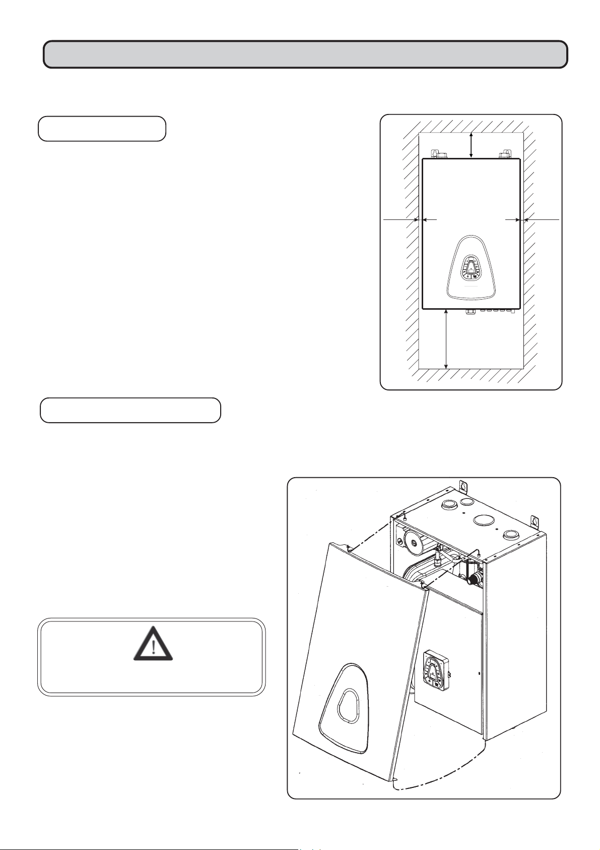
• The boiler must be located at least 300mm above any object to
allow the elements to be removed. At least 100mm is required at
the top of the boiler to allow for connection of pipework.
• 10mm is required at the sides of the unit.
• The boiler must be mounted on an internal solid masonry wall
capable of withstanding the weight of the product when full of
water.
• Consideration should be given to the rounting of electric cables to
the product and the wiring to a thermostat (if used).
• The location must be free from frost and excessives moisture.
2.2 - Fitting the boiler
10
100
10
300
2.21 - Opening case
The boiler may be opened by unscrewing the
bottom two bolts a couple of turns (they do not
need to be removed completely). The front
cover may then be pulled out from the bottom
and lifted off the two top pins.
Switch off the electricity supply to the
boiler before opening the internal cover.
Ascari - 12kW -page 8 -
Page 9
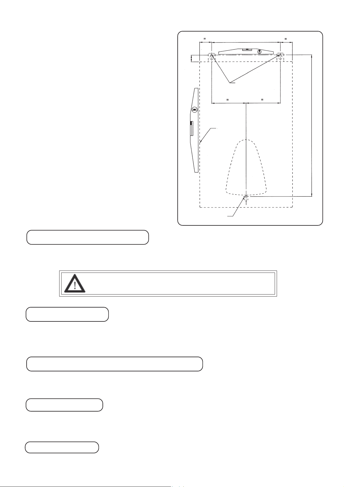
2.2.2 - Main unit
• Once the location of the boiler has been selected,
mark the hole positions as per firgures below. Use
a spirit-level to ensure the holes are aligned
correctly. Access to the bottom screw hole is
achieved by removing the bottom element plate.
• Once marked out, drill 8mm diameter holes and
plug with masonry plugs. Screw in high strengh
screws to a depth that allows the inner face of the
screw head to protrude from the wall a distance to
allow the mounting plates at the rear of the boiler
to engage (approx. 5mm).
• With suitable equipment or an assistant raise the
boiler to the fixing point and ensure each screw
has engaged into the mounting slots. Tighten the
screws to secure the boiler to the wall.
• Once fixed to the wall the boiler may be plumbed
into the central heating system.
29
Overall frame
pattern
300
Ø8 screw plug
605
Ø8 screw plug
2.3 - Hydraulic connection
Connections to heating circuit are located atop the boiler. Left connection for outflow, right connection for
backflow (see § 1.2).
UU
HEAHEA
HEA
HEAHEA
SESE
U
SE
SESE
UU
TINGTING
TING
TINGTING
MANDMAND
MAND
MANDMAND
OUTFLOUTFL
OUTFL
OUTFLOUTFL
AA
TT
A
T
AA
TT
OO
WW
O
W
OO
WW
ORILORIL
ORIL
ORILORIL
ANDAND
AND
ANDAND
YY
Y
YY
BRASSBRASS
BRASS
BRASSBRASS
BB
AA
CKFLCKFL
B
A
CKFL
BB
AA
CKFLCKFL
CONNECTCONNECT
CONNECT
CONNECTCONNECT
OO
WW
WITHOUTWITHOUT
O
W
WITHOUT
OO
WW
WITHOUTWITHOUT
ORSORS
ORS
ORSORS
SUPPLIEDSUPPLIED
SUPPLIED
SUPPLIEDSUPPLIED
REMOREMO
REMO
REMOREMO
VINGVING
VING
VINGVING
ONON
ON
ONON
THEMTHEM
THEM
THEMTHEM
..
.
..
2.4 - Mixing valve
Ascari installed boiler easily support a backflow temperature higher than the ambient temperature of
surrounding area, which makes unnecessary the use of a mixing valve.
2.5 - Expansion - Pressure safety relief
Expansion is collected by a pressurized 8 liters vessel.
Safety relief bleeder must be connected to a bleed collector with drain (see § 1.2).
2.6 - Antifreeze
Use ethylene glycol only with incorporated corrosion inhibitor .
Glycol ratio must be under 10 %.
2.7 - Bleeding
Make sure to have a bleeding point at the highest level of the hydraulic circuit.
Ascari - 12kW -page 9 -
Page 10
2.8 - Plumbing
• The system should be flushed prior to connecting the boiler to remove all particles from the pipework. Do
not use the fitted pressure relief valve to flush the system as particles trapped in the valve will cause
incorrect valve operation.
• At least one air bleeding device should also be connected to the highest point of the plumbing system to
remove trapped air and ensure silent running of the heating system.
• If using radiators with Thermostatic Radiator Valves a bypass radiator must be fitted with lockshield valves
that will allow a flow of 350 litres/hour.
• Service valves should be connected to the inlet and outlet of the boiler for easy maintenance.
• Although the boiler can operate without a room thermost at this is required for automatic adjustment of boiler
output temperature.
• Where underfloor heating is being used, the 60°C thermal cut-out must connected in place of the factory
selected 100°C device (see section 1.3.1).
• A drain cock is required to be fitted in the lowest part of the heating system to allow the system fluid to be
drained fully.
• A filling loop must be installed that isolates from the cold mains water supply from the heating system and
complies with the current building and water regulations in force at the time.
• The boiler incorporates an 8-litre expansion vessel which is suitable for heating systems as follow :
Initial system pressure (bar) 0,50 0,75 1,00 1,50
Total water in heating system (litres) 96 84 73 50
For larger systems Multiply the volume water by these factors 0,0833 0,093 0,109 0,156
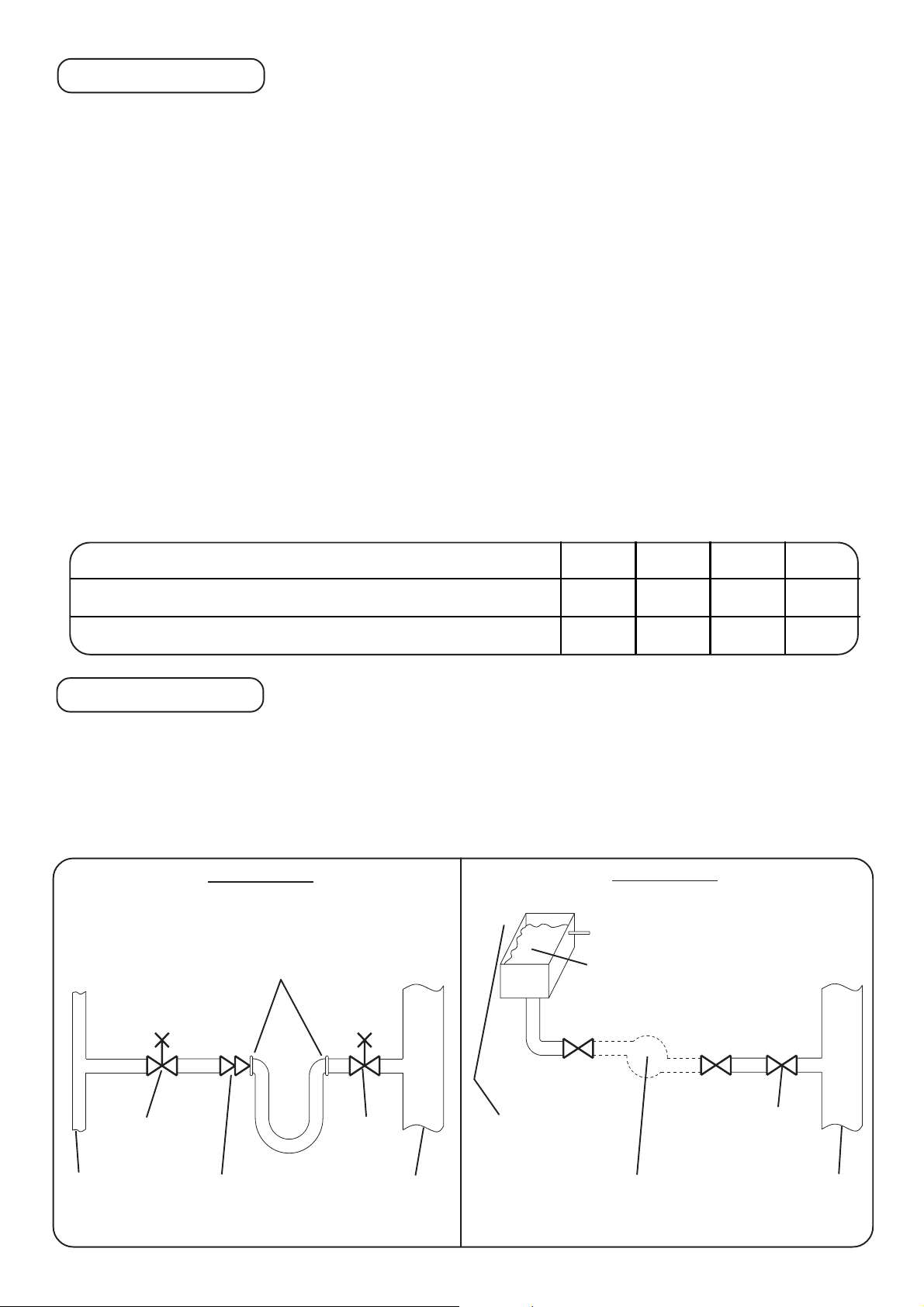
2.9 - Filling loop
This boiler is not fitted with a filling loop. Any filling loop being fitted should comply with the water supply (water
fittings) regulations 1999 Section G24.1 and G24.2. A filling loop should be fitted at some point to allow the CH
system to be filled.
Two tipes are shown below : METHODS OF FILLING A SEALED SYSTEM
Recommended and appro v ed method for filling closed circuits in a house.
(R24-2a Water Regulations Guide)
METHOD A
T emporary Flexible Hose
Connection
T o be removed
immediately after filling
F
METHOD B
Cistern &
Overflow
F
Mains
water
supply
Stop
valve
Double
check
valve
assembly
Stop
valve
Heating
System
Return
Ascari - 12kW -page 10 -
Mains
water
supply
Pressure Pump &
reducing valve
(if required)
Stop
valve
Heating
System
Return
Page 11

3 - ELECTRIC CONNECTIONS
IMPORTANT NOTICE
Electric connections might be loosed during transportation.
To avoid abnormal overheat, carefully check quick connection terminals and screwed connections.
• Wiring external to the appliance must be in accordance with the current I.E.E. Wiring Regulations (BS
7671) for electrical installation and any local regulations, which apply .
• With the boiler plumbed in the electrical connections can be made to the boiler :
• This appliance must be earthed !
• The Ascari boiler comes with cage-clamp connectors. These are operated using a 2.5mm x 0.4mm blade
screwdriver for accessory terminals and 3.5mm x 0.5mm blade screwdriver for power terminals.
• The boiler should be permanently connected to the electricity supply , direct from a 63A fused supply on the
consumer unit wia a double pole linked switch with minimum contact gap of 3mm. No other appliances
should be powered from this supply .
• To connect a wire, insert the blade of the screwdriver into the opening located just above or below the
central mark of the terminal block and pivot the blade towards the centre. The wire may then be inserted
into the cage and the screwdriver blade removed.
• External command (a phase 230V common to the boiler must be connected to terminal 25).
• The power supply cable should be routed through the large cable entry point at the bottom of the boiler. If
desired the cable entry may be moved to the top of the boiler by removing the self sealing nut from the
bottom to the top entry point.
• The Earth wire should be connected to the top terminal marked with the Earth symbol.
• The Neutral wire should be connected to the large terminal marked "N".
• The live wire to the large terminal labelled PH.
• Do not switch on the electricity supply until asked to do so in the Commissioning and Testing section.
• As a minimum it is recommended that a room thermostat be installed to control the appliance. Thermost atic
radiator valves may be fitted to the system, however they must not be fitted in the room where the room
thermostat is fitted. There must be at least one radiator installed with lock shield valves that should not be
closed and will allow 350 litre/hour circulation. Further guidance can be obtained from the Domestic Heating
and Hot Water Guide to the building regulations.
Ascari - 12kW -page 11 -
Page 12

3.1- Electric flow rate, number and cross-section of the power
connectors, fuse protection
3.1.1 - Electric datas
Amperes for each phase
Maximum output P1Boiler
230 V mono
ASCARI 12
12 kW 52 A
3.1.2 - Number and cross-section of connectors
IMPORTANT
Follow local existing regulations regarding electric connections
Electric connections to mains must be installed according to local and national regulations, which generally
specify:
• Type of connectors :
- Type of slipcover
- Number and cross-section of wires,
- etc...
• Type of inst allation :
- Magnetic interferences inside bundles,
- Ambient temperature,
- Open or covered wires,
- Length of cords,
- etc...
Example: Cord type U1000, loose in open air rack, ambient temperature 20°C, lenght 15 m.
MINIMUM cross-section for each connector in mm²
Boiler
Maximum
output P1
and number of connectors for above example
230 V mono
Ph = Phase = 16²
ASCARI 1 2
12 kW 2 x 16² + T *
N = Neutral = 16²
Ascari - 12kW -page 12 -
Page 13

Boiler
Maximum
output P1
MAXIMUM cross-section for each connector in mm²
and number of connector for above example
230 V mono
ASCARI 1 2
* : Cross-section of ground connection must be equivalent to cross-section of largest phase/neutral.
Manufacturer cannot be, for any reason, regarded as faulty in case of improper choice of connection
wires to mains, or in any case of damages resulting from installation solutions.
12 kW
2 x 16² + G *
3.1.3 - Fuses
Fuses for connection to mains
230 V mono
Boiler
Maximum
output
P1
ASCARI 1 2
12 kW 63 A
Ascari - 12kW -page 13 -
Page 14

3.2 - Power terminal
Put the self-sealing nut (supplied with the boiler) for
connection to mains from the bottom of the casing.
Put the self-sealing nut (supplied with the boiler) for
connection to mains from the top of the casing. In
this case remove the plastic cap and close the hole
below casing using same.
or
Screw A
5 self-sealing nuts for accessories connections
(Ambience thermostat, outside and/or Domestic Hot
Water sensor and remote cut-out)
Connections are cage-clamp terminals, to be used as to follow :
- For accessories terminals use a 2,5 x 0,4mm blade screwdriver
- For power terminal use a 3,5 x 0,5mm or 5,5 x 0,8mm blade
screwdriver.
Plastic cap moved from top
to bottom
1:Introduce the blade of the driver into the opening located just
above or bellow the mark with a slight pivoting move to center.
2:Introduce the connector's terminal inside the cage.
3:Remove the screwdriver
Ascari - 12kW -page 14 -
Page 15

3.3 - Connection to mains depending on power supply
Ground
Neutral
: see § 3.1 for connectors cross section
and requested fused switch or
Phase
electro-thermic breaker.
I
OTE : Denuded length of wires between 16 and 17mm
N
Ascari - 12kW -page 15 -
Page 16

3.4 - Regulation circuit drawing
phase
A1
A2
brown
11
14
brown
S.Ext
external
command
25
red
R
brown
R
L1
1
brown
2
white
SC
white
grey
5
grey
6
pink
3
pink
4
F
red
blue
orange
black
CP
7
8
grey
yellow
white
white
A1
A2
C1
K1
yellow
A1
A2
K2
red
A1
K3
black
A1
K4
A2A2
blue
CC
60°C
neutral
blue
N
9
10
11
DT
blue
AQS1
blue
T
Decoding :
L1 : Phase
N : Neutral
F : 4A fuse size 5 x 20
C1 : Electronic card with display
C C : 3 speed pump
SC : Boiler's sensor
AQS1 : 60°C safety limitator with manual reset
blue
100°C
AQS2
T
blue
12
DP1
13
blue
14
15
DP2
AQS2 : 100°C safety limitator with
manual reset
K1 to K4 : 20A power breakers
DT : Total cut-out (remove the bridge)
DP1 & DP2 : Partial cut-out (remove the bridge)
R : External command relay
S.Ext : Outside Temperature sensor
Ascari - 12kW -page 16 -
Page 17

3.5 - Control accessories wiring
CC
11
1
R
2
S.Ext
14
43
1 - 2 : External command relay contact
3 - 4 : Outside temperature sensor
10 - 1 1: To tal cut-out DT (remove the bridge) and / or 65°C heating
6
5
floor safety limitator (mandatory) with manual reset.
7
8
9
1110
12
External
command
1413
15
25
See § 1.3.1.
12 - 13: Partial cut-out DP1 (remove the bridge)
14 - 15: Partial cut-out DP2 (remove the bridge)
25 : External command (use phase 230V common to the
boiler on pin L1)
• To avoid electro-magnetic interferences, power connection and sensors connections will be
isolated. Also avoid using diversion box.
• Connectors will be of electrolitic quality brass (no corrosion of denuded ends at connection
points).
• Never use telephone wire (cross-section of sub-connectors too thin and easy breakable at
connections points).
• Cross-section of connectors must be between 0,5 and 1mm².
Ascari - 12kW -page 17 -
Page 18

3.6 - Wiring diagrams
GND 1
blanc
pressure sensor power
gris
+Vdc 2
3
OUT 4
pressure sensor connect.
jaune
pink
pink Outside sensor (S.Ext)
grey
grey DHW sensor (S.ECS)
white
SC
white
brown
brown
ambience thermostat (T A)
boiler's sensor (SC)
black
GND
OUT
+Vdc
red
F
orange
230 V / 12 V
adaptator
Heating pump CC
DHW pump C.ECS
6
5
4
3
2
1
230V power
blue
black
red
yellow
white
brown
red
black
white
brown
S.Ext
13
4
2
5678
green
yellow
brown
CC
blue
10
9
blue
PH
11
12
13 14
PH
15
white
AQS 1
blue
60°C
white
AQS 2
100°C
PH
red
red
black
blue
black
NNNPH
NPH
blue
(1)
: In optionnal
PH : Phase
N : Neutral
F : 4A fuse size 5 x 20
C 1 : Electronic card with display
C C : 3-speed pump
TA : Ambience thermostat
TT
Légende :
AqECS : Domestic Hot Water Safety limitor
ou
(1)
SExt
SC : Boiler's sensor
Ascari - 12kW -page 18 -
blue
: Outside sensor
Page 19

black
red
yellow
white
red
black
white
brown
brown
blue
12
14
11
a1
a2
white
L1
L2
L3
L4 A1
yellow
K2
T1
T2
T3
red
L1
red
L2 L3
R
25
white
balck
L4
white
A1
T4
A2
bleu
L1
red
L2
K1
T1
red
T2
black
T3
T4
A2
blue
T2
T1
red
balck
white
L1 L4 A1
L2 L3
K4
T1
white
black
L4
A1
L3
K3
A2
T4T3
blue
red
black
T4T3T2
A2
blue
T1 T2
bleu
bleu
AQS1 : 60°C Safety limitor with manual reset
AQS2 : 100°C safety limitor with manual reset
Ascari - 12kW -page 19 -
Légende :
K1 to K4 : 20A power breakers
T1 & T2 : 6kW heating elements
Page 20

3.7 - Heating elements connections
Connections of the heating elements will have to be adjusted according to requested output, depending on
the volume and the insulation of the space to heat.
R
WBl WBlR
BBBB
BB
R
WBl WBlR
BBB
BB
12 kW 10 kW*
ex-work wiring
R
R
WBl WBlR
WBl WBlR
BBB
B
8 kW* 6 kW*
RBBWBl WBlR
4 kW*
View from bellow
* Remove bleu connectors between power terminal and elements
according to drawing.
See § 1.4 to access elements.
BB
B
R : Red
Bl : Black
W : White
B : Blue
Ascari - 12kW -page 20 -
Page 21

4 - BASIC HYDRAULIC PATTERNS
1234
1234
1234
1234
Commissioning & T esting
WATER TREATMENT, CLEANSING AND FLUSHING THE HEATING SYSTEM
NOTE : Bristish Standard BS7593 : 1992 stresses the importance of cleansing and flushing of the system to
ensure it continues to run efficiently with the minimum of maintenance necessary . Dimplex fully support this
professional approach and recommend that the system is cleased with an effective chemical cleanser and
protected long term with a suitable inhibitor. Such product s are available from Fernox and Sentinal.
• Check the pressure of the expansion vessel, this should be factory set to 1 bar (0.1MPa)
• The heating system should be filled using the approved installed filling loop.
Ensure all radiator valves are open. The initial system pressure when cold should be between 1.0 (0.1MPa)
and 1.5 bar (0.15MPa)
• Once filled check the system for leaks
• Open the drain cock and drain the system fully
4.1 - Direct heating circuit
TA
Rm
Underfloor heating
Rt
Radiators
OR
4
1
2
electric boiler
4
RD
3
6
5
5
Decoding :
1 : 3 speed pump
2 : 8 liters expansion vessel
3 : 3 bar safety relief
4 : Stopcocks
5 : Automatic air bleeders
6 : Pressure sensor
D : Heating outlet 1" female
R : Heating inlet 1" female
Rm : Handcock (room housint the ambience thermostat TA)
Rt : Thermostatic cock
TA : Ambience thermostat with or without timer
SExt : Outside temperature sensor
Ascari - 12kW -page 21 -
SExt
Page 22

5 - 3 SPEED WATER PUMP
IIIIII
III
IIIIII
IIII
II
IIII
II
I
II
3 speed (I, II et III) water pump for adjustment to operating needs, depending on insulation and circuit
The boiler is factory set at pump speed 3, for lower pump speeds the selector in the centre of the pump may
be turned to 1 or 2 using a large flat bladed screwdriver .
Electric datas
Speed
III 90 0,40
II 67 0,30
I 47 0,20
Nominal
output (W)
Nominal
intensity (A)
Ascari - 12kW -page 22 -
Page 23

6 - 2 CIRCUITS ELECTRONIC REGULATION
6.1 - Generalities
- Possible monitoring of the heating circuit water pump to the external command for a better adjustment.
- Possible automatic adjustment of the requested temperature when using an external command without
timer.
- Choice of manual or automatic operating (with outside sensor)
- Manual or automatic shift to Summertime or Wintertime mode (with outside sensor)
- Step-by-step st art and/or stop of the four power stages (with 1 to 6 min intervals) with overheat protection.
- Cyclic weekly shift of the 4 power stages starting sequence.
- Cycles counter for each power stage.
- Water pump unstickage in Summer mode.
- Frost protection of the Domestic Hot Water and heating circuits when the boiler is off.
Ascari - 12kW -page 23 -
Page 24

bar
° C
6.2 - Control pannel description
Usual operating functions
Boiler's temperature display in °C.
When the boiler is off and the two
middle horizontal LEDs on, antifrost
protection is operating.
(flashing in case of sensor failure)
Summer mode green LED
Used to decrease
temperature during settings
(instant touch) or cancell
operating postponement of
running power stage (press
3 sec)
(Glittering • displays normal
operating)
Winter modegreen LED
Used to increase
temperature during settings
(instant touch)
Operating display red LED
Hot Water selection (if fitted)
On/Off switch (with
automatic anti frost
protection for DHW and
heating circuits) (instant
touch)
Auto
Manu
Pressure display in bar.
Boiler stops automatically below 0,3 bar
with automatic reset over 0,5 bar .
(0,2 blinking displays a pressure loss -
other value flashing displays a
pressure sensor failure)
Ascari - 12kW -page 24 -
Used to enter requested
heating temperature menu
(instant touch) or start the
winter mode (heating and
DHW) (press 3 sec.)
Used to choice manual or
automatic operating (press 3
sec. + instant touch) (with
outside sensor
Page 25

6.3 - Regulation settings
For fitter's use only .
The regulation must be adjusted according the use of the boiler .
• Press
• Parameter # starts blinking in front of "°C"
• Press
• To start setting the displayed parameter press or (instant touch).
• The parameter value, i.e*
• Press or (instant touch) to change setting.
• Press
and (3 sec) to start setting menu for 4 minutes.
or (instant touch) to select next parameter, i.e °C, ... until °C
starts blinking in front of "bar".
or (instant touch) to confirm setting and return to setting menu.
• Press and (3 sec) any time to exit the setting menu.
* When outside minimum temperature (TEMI) below 0°C, a glittering point is on display right at bottom of
displayed figure : ie
in front of "bar" means -5°C (and not 5°C)
Ascari - 12kW -page 25 -
Page 26

PARAMETERS LISTING
A
Press and during 3 sec to access parameters menu.
Available if Paremeter # Description Setting range Ex-wo rd settings
Electric boiler (no = O ; yes = 1) 0 or 1 1 mandatory
Maximum requested boiler's temperature
si = 1
(1)
(TCMA)
Minimum requested boiler's temperature
(1)
(TCMI)
External command installed
(no = O ; yes = 1)
Heating circuit pump linked to exter nal
comm and (no = O ; yes = 1)
21 to 80°C 80°C
21 to TCMA °C 30°C
0 or 1 0
0 or 1 0
si = 1
Autoadaptability or automatic adjustment of the
requested temp erature (no = O ; yes = 1)
0 or 1
(2)
0
Outside se nsor (no = O ; yes = 1) 0 or 1 0
(1)
si = 1
si = 1
si = 1
si = 1 DHW sensor (no = O ; yes = 1)
si = 1
si = 1
si = 0
si = 0
si = 0
si = 0
si = 0
si = 0
(1)
: See § 7 to set the heating diagram according to 4 paremeters (TCMA, TCMI, TEMA and TEMI)
(2)
: Prohibited when using a scheduled external command
(3)
: Depending on water flow rate and volume inside the heating circuit, the boiler might start at very short intervals with
Maxim um outside tem perature (TEM A) 11 to 25°C 20°C
(1)
Minimum outside tem perature (T EMI) -30 to +10°C -5°C
utomatic ti pping up summer mode
(no = O ; yes = 1)
Operating postponement
Domestic Hot Water production
(no = O ; yes = 1)
Legionnai re s disease free mode (off)
(no = O ; yes = 1)
Engaging of 6 pow er stages
(no = O ; yes = 1)
Engaging stage 1
(no = O ; yes = 1)
Engaging stage 2
(no = O ; yes = 1)
Engaging stage 3
(no = O ; yes = 1)
Engaging stage 4
(no = O ; yes = 1)
Engaging stage 5
(no = O ; yes = 1)
Engaging stage 6
(no = O ; yes = 1)
0 or 1 0
1 to 6 min
(3)
0 or 1 0
(4)
0 or 1
(5)
0 or 1
0 or 1 1
0 or 1 1
0 or 1 1
0 or 1 1
0 or 1 1
0 or 1 1
0 or 1 1
2 min.
1
0
wear and tear resulting. To reduce the number of cycles, increase postponement.
(4)
: No = 0 = with electromechanical sensor (Temperature setting achieved on the water sensor, not on the control
panel). In this case, no antifrost control for the Domestic Hot Water.
(5)
Yes = 1 with element sensor. Domestic Hot Water antifrost control is operating.
: Warning: The Legionnaires Disease Free mode will increase the Domestic hot Water temperature up to 65°C. A
thermostatic mixer is then mandatory at Domestic Hot Water outlet to avoid scalding.
N
OTE : To reset autoadaptability, zero parameter # , then set value to 1.
Ascari - 12kW -page 26 -
Page 27

6.4 - Operating
Display in front of symbol "°C" means the boiler is off, connected to power supply, with anti frost
protection operating (boiler starts automatically when the boiler's temperature or the Domestic Hot Water
temperature turns below 5°C).
Press
to turn the boiler On or Off.
6.4.1 - Automatic / Manual Operation
The boiler must be set to Manual operation as follows :
Press and hold the Auto/Man button for 3 seconds. The display will show Au or Man, press the Auto/Man
button again for a short period to toggle the display so that it shows Man. With the correct display showing,
press and hold Auto/Man for 3 seconds to return to normal operating mode.
6.4.2 - Requested heating temperature setting in manual mode
Press to display the requested temperature blinking in front of symbol "°C".
Press or to or decrease the requested temperature between TCMI and TCMA. (see § 6.3).
Press to confirm setting.
6.4.3 - Summer / Winter shift
(Available in manual mode only (see § 6.4.1 above)
Press during 3 sec to start the summertime mode and lit Summertime LED;
Press during 3 sec to start the wintertime mode and lit the Wintertime LED.
Ascari - 12kW -page 27 -
Page 28

6.4.4 - Programming the maximum output setting of the boiler
To allow the power supply of the boiler with small size connectors and fuses (see
§ 3.1) it is mandatory to disconnect the heating elements (see § 3.7) to fully stop
the power supply of the boiler.
The boiler is delivered with a maximum output of 12kW (parameter = 1).
Set the parameter = 0
Set parameters of to to requested value according following tables to adjust the maximum
output of the boiler :
Power stage #
Power stage value
Parameter number
Parameter value
to obtain the
requested
maximum output
(0 = no ; 1 = yes)
12 kw110101
10 kW100101
8 kW100100
6 kW100001
4 kW010001
123456
4 kW 2 kW 0 kW 4 kW 0 kW 2 kW
6.4.5 - Temperatures display
During normal operating the boiler's temperature, i.e : is on display in front of symbol "°C".
1st pressure on
displays the ambience sensor display.
Parameter #
external command status is on display in front of "bar" :
2nd pressure on
(or 1st if no external command) displays the outside temperature. Parameter #
is displayed in front of symbol "°C"
for boiler's run not requested
for boiler's run requested
is displayed in front of symbol "°C". Outside temperature can be read on bottom display i.e with a
glittering LED down right the display if a negative value (-5°c in this example).
3rd (or 2nd or 1st) pressure displays the temperature correction in °K (parameter #
)
(see § 6.3 to zero this correction).
Ascari - 12kW -page 28 -
Page 29

6.5 - Counters
The regulation is equiped with 6 counters to count heating cycles (the unit is 100 cycles).
Press
The setting menu starts (see § 6.3).
Press
meaning power breaker #1 K1 is totalling more than 0999 x 100 = 99.900 cycles.
Press
St arting this menu will automatically restore the weekly shift of the 6 power stages starting sequence back to
the 1 to 6 order, but will not zero the counters.
Press
and during 3 sec.
during 3 sec. : °C will be on display for counter #1, alternating with °C and bar,
to shift to counter #2. Conversely press to return to previous counter.
and during 3 sec. to exit the counters menu.
6.6 - Failures display
The boiler has many selectable options. Please ensure the correct selections are made for the type of
installation you have made. If you have selected the use of a room thermostat, or hot water cylinder , the boiler
will not operate until these devices are connected.
The boiler indicates a boiler fault by flashing all segments of the temperature display.
In case of boiler's temperature failure, all 14 LEDs
the water pump still running.
In case of Domestic Hot Water sensor failure, all 14 LEDs
boiler is automatically restricted to heating.
In case of outside temperature sensor failure, all 14 LEDS
restricted to heating.
Please call the Dimplex Customer Service department -see Servicing section2 FLASHING SEGMENTS in front of bar -indicate the system pressure has fallen below the minimum operating
pressure.
• Check if water has discharged from the pressure relief valve. If so call a Dimplex service agent.
• Check for leakage in the system.
Once the fault has been cleared the boiler will turn on again if the system is filled and pressurised to over 0.5
bar.
in front of symbol "°C" are blinking. The boiler is off,
in front of symbol "°C" are blinking. The
in front of "°C" are blinking. The boiler is
Ascari - 12kW -page 29 -
Page 30

Servicing
It is recommended that the boiler be installed and serviced regularly by a Dimplex service agent to ensure
continual trouble-free operation. For details of service agents in your area please contact :
Glen Dimplex UK Limited
Millbrook House
Grange Drive
Hedge End
Hampshire
S030 2DF
Dimplex customer Services on 0870 727 0101
Ascari - 12kW -page 30 -
Page 31

7 - HEATING DIAGRAM
The heating diagram will be set according the following four parameters (see § 6.3) :
- TCMA = Maximum boiler's temperature
- TCMI = Minimum boiler's temperature
- TEMA = Maximum outside temperature
or temperature of summer/winter shift
- TEMI = Minimum outside temperature
or basic outside temperature
7.1 - Underfloor heating
The boiler is delivered with a 100°C safety limitator , to lower the maximum boiler's temperature at 60°C (see
§ 1.3.1).
T ypical use :
Requested boiler's temperature TC (°C)
80
70
60
TCMA = 50°C
Max with floor
heating
TCMI = 21°C
50
40
30
20
10
-30
-25 -20
-15 -10
TEMI = -5°C
-5
0 5 10 15 2520
Outside temperature Text (°C)
7.2 - Radiators
Ex-work factory settings with a 100°C boiler's temperature limitator.
T ypical use :
Requested boiler's temperature TC (°C)
80
TCMA = 70°C
TCMI = 40°C
70
60
50
40
30
20
10
TEMA = 20°C
-30
-25 -20
TEMI = -15°C
-15 -10
Ascari - 12kW -page 31 -
-5
0 5 10 15 2520
Outside temperature Text (°C)
TEMA = 18°C
Page 32

7.3 - Specific heating diagram
Requested boiler's temperature TC (°C)
80
70
60
50
40
30
20
10
-30
-25 -20 -15 -10 -5 20
0 5 10 15 25
Outside temperature Text (°C)
Ascari - 12kW -page 32 -
Page 33

8 - MAINTENANCE
Once a year we recommend to have the boiler checked by a qualified technician.
- Pressure inside the heating circuit needs to be controlled a a regular basis (pressure when cold will have to
remain over 1 bar).
- Frist a few days after cut-over , later at least once a year, check electric connections tightness of the heating
elements and power supply.
9 - TROUBLESHOOTING
- Floor heating: In case of overheat the temperature limitator (60°C) will cut power supply to heating
elements .
- Radiators: The limitator (100°C) also cuts power to heating elements.
- Af ter solving the failure, reset the boiler pressing the small red button in the middle of the sensor's head.
(see §1.3.1).
- Numerous power losses or lack of power: it might happened one (or several) connection(s) from power to
heating elements is(are) defective (powerloss) or cut (power failure). In this case change defective element(s).
Cut the power supply , drain, disconnect elements, remove elements fastener and remove/replace damaged
element(s). (seer § 1.2 to access heating elements).
Front view
(electric box removed)
View from below
(Access trap-door to elements removed)
Heating elements
O-ring
Ascari - 12kW -page 33 -
element fastener
Heating elements
Page 34

Fastening the pump
If the pump is producing some abnormal noise, slightly unscrew without creating leackage, then screw
again following instructions below .
1 - screw two opposite screws with a stroke of 3
Nm.
3 - screw the first two opposite screws with a
stroke of 5 Nm.
SPARE PARTS LIST
Designation Reference
Side casing
Front casing
2 - screw the other two opposite screws with a
stroke of 3 Nm
4 - screw the last two opposite screws with a
stroke of 5 Nm.
0105276
12 MA
230 V mono
B4484737 1
B4484730 1
Control panel
Pump
Klixon 60°
Klixon 100°
3bar relief valve
8L expansion vessel
Water sensor
Outside sensor (option)
6kW heating element
Heating element gasket
20A tetrapole switch
Fuse holder
4A fuse size 5 x 20
Display
C1 electronic card
B1758741 1
B1243544 1
B1243400 1
B1243418 1
B1239103 1
B1472534 1
B1243546 1
B1243586 1
B1243558 2
B1657044 3
B1243561 4
B1243146 1
B1243147 1
B1943599 1
B1943600 1
Temperature display
B1243534 1
Ascari - 12kW -page 34 -
 Loading...