

Page 1
Ascari MA12 -p. 1 -
INSTALLATION GUIDE
Ref. : 1871184 - 0107103
ASCARI MA12
ELECTRIC HEATING BOILER
Page 2

Ascari MA12 -p. 2 -
1 - Installation ans configuration.................................................................................... p. 03
1.1 - Quick reference guide................................................................................................................ p. 03
1.2 - Install options............................................................................................................................. p. 04
1.3 - Boiler (serial numbers of 0500151 and over)............................................................................. p. 05
1.4 - Menu options ............................................................................................................................. p. 06
1.5 - Summer / Winter mode ............................................................................................................. p. 07
1.6 - Underfloor heating ..................................................................................................................... p. 07
2 - Installation and Devicing instructions.......................................................................p. 08
2.1 - Introduction ................................................................................................................................ p. 08
2.2 - Important information ................................................................................................................. p. 09
2.3 - Technical specification ............................................................................................................... p. 10
2.4 - Preparation ................................................................................................................................ p. 11
2.4.1 - Opening case ................................................................................................................ p. 11
2.4.2 - Electrical compartment ................................................................................................. p. 12
2.4.3 - Selecting thermal cut-out .............................................................................................. p. 12
2.5 - Installation requirements............................................................................................................ p. 13
2.5.1 - Location......................................................................................................................... p. 13
2.6 - Installation.................................................................................................................................. p. 13
2.6.1 - Main Unit....................................................................................................................... p. 13
2.6.2 - Plumbing ....................................................................................................................... p. 14
2.6.2.1 - Radiators/Underfloor ...................................................................................... p. 14
2.6.3 - Filling loop..................................................................................................................... p. 15
2.7 - Electrical .................................................................................................................................... p. 16
2.7.1 - Power selection ............................................................................................................. p. 17
2.8 - Commissioning and testing........................................................................................................ p. 17
2.9 - Boiler configuration.................................................................................................................... p. 18
2.9.1 - Automatic / Manual operation ....................................................................................... p. 19
2.10 - Pump speed............................................................................................................................. p. 19
2.11 - Troubleshooting........................................................................................................................ p. 19
2.12 - Servicing.................................................................................................................................. p. 19
2.13 - Dimensions - hydraulic connections ........................................................................................ p. 20
2.14 - Power terminal......................................................................................................................... p. 21
2.15 - Connection to the electricity .................................................................................................... p. 22
2.16 - Regulation circuit drawing........................................................................................................ p. 23
2.16.1 - Operating from a switched live.................................................................................... p. 23
2.16.2 - Direct room thermostat connections and direct cylinder thermostat ........................... p. 24
2.17 - Control accessories wiring ....................................................................................................... p. 25
2.17.1 - Operating from a switched live.................................................................................... p. 25
2.17.2 - Direct room thermostat connections and direct cylinder thermostat ........................... p. 26
2.18 - Wiring diagrams....................................................................................................................... p. 27
2.19 - 3 Speed water pump................................................................................................................ p. 29
2.20 - Control pannel description ....................................................................................................... p. 30
2.21 - Regulation settings .................................................................................................................. p. 31
2.22 - Operating ................................................................................................................................. p. 33
2.22.1 - Automatic / Manual operation ..................................................................................... p. 33
2.22.2 - Requested heating temperature setting in manual mode............................................ p. 33
2.22.3 - Summer / Winter shift ................................................................................................. p. 33
2.22.4 - Programming the maximum output setting of the boiler ............................................. p. 34
2.22.5 - Temperatures display .................................................................................................. p. 34
2.23 - Counters .................................................................................................................................. p. 35
2.24 - Failures display........................................................................................................................ p. 35
2.25 - Maintenance ............................................................................................................................ p. 36
2.26 - Troubleshooting ....................................................................................................................... p. 36
CONTENTS
Page 3

Ascari MA12 -p. 3 -
1 - INSTALLATION & CONFIGURATION
1.1 - Quick reference Guide
1. It is recommended that the boiler be connected to a 10hour or similar off-peak tariff that provides some
daytime off-peak hours.
2. Where the off-peak tariff is restricted a changeover relay should be used to switch power to the boiler
when the off-peak supply is not available.
3. Fill the system with water prior to turning on the electrical supply to the boiler.
4. Ensure the system is flushed thoroughly before letting any air/water exit through the pressure relief valve
(dirt can prevent the valve closing).
5. Check the system is full by turning the pressure relief valve cap, and check water exits correctly through
the discharge pipe.
6. A manual pressure gauge should be used to check the system pressure when cold. The pressure should
be set between 1 bar & 1.5bar. Note all air should be removed from the system before measuring the
system pressure.
6a Alternative with the electric supply off, the yellow bridge between terminals 10 and 11 may be removed
before filling the system for the final time ( this prevents the elements turning on) and the boiler pressure
gauge used to set the cold system pressure. Once set to 1-1.5bar, the boiler should be switched off and
the yellow bridge returned to its position between terminals 10 & 11.
Page 4
Ascari MA12 -p. 4 -
1.2 - Install Options
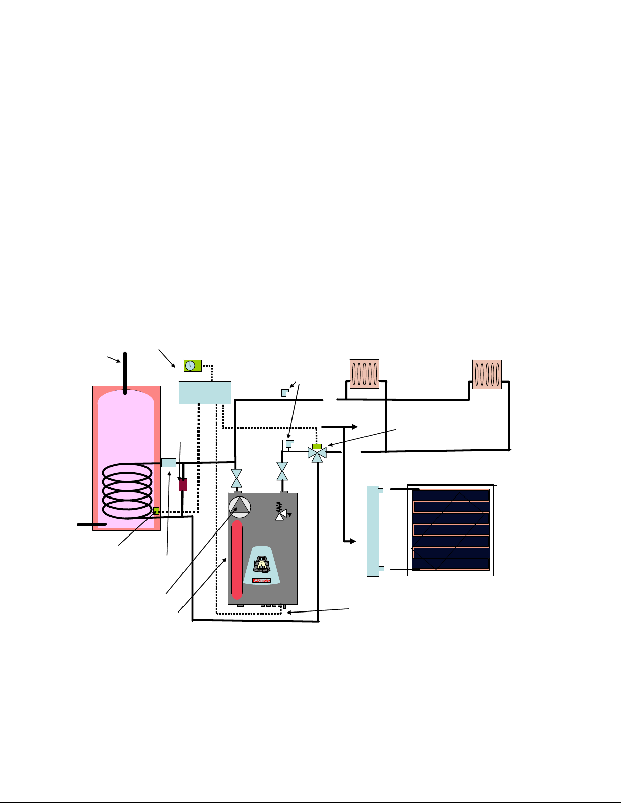
1. SPACE HEA TING ONLY (recommended)-direct room thermostat Connection
• The no-volt contacts of the room thermostat should be connected to terminals 1 and 2 of the boiler.
• Menu option 4 should be set to 01 to allow the boiler to be controlled from the room thermostat.
2. OPERATING WITH HOT WATER CYLINDER
Dimplex recommend to use a direct electric unvented cylinder for the production and storage of the hot water
as this is cheaper than an indirect cylinder, requires less plumbing (piping and valves) and is more thermally
efficient.
Installation Configuration –Heating & Hot Water
ManMan
AutoAuto
+-
ManMan
AutoAuto
+-
ManMan
AutoAuto
+-
0 bar0 bar
4 bar
or
U
nde
r
F
l
o
o
r
H
ea
t
i
n
g
8 litre Expansion vessel
3-speed pump
Room
thermostat
3-port diverter valve
3bar pressure
relief valve
Air bleeders
Hot water
outlet
Cylinder
thermostat
manifold
Differential
Pressure
Valve
W-Plan
10 way connector
Switched Live
Two-port valve
Two-port
valve
When using the boiler for unvented hot water and heating, the two-port motorised valve should be inserted in
the flow from the boiler. A Differential Pressure valve should then be connected between the flow and return at
a point between the boiler and the two-port motorised valve.
Page 5

Ascari MA12 -p. 5 -
1.3 - Boiler (serial numbers of 0500151 and over)
Two options are available:
Option 1 - Operating from a Switched Live
Switched Live
1. The switched live from the 10-way connector block should be connected to terminal 25, which is located
beside the relay located in top right of the boiler.
2. In the set-up menu, set option 04 to 1
3. Auto-adaptability (option 6 of the set-up menu) should be turned off.
4. The minimum central heating circuit temperature (option 3 of the set-up menu) should be selected to
provide central heating and hot water safely.
5. The boiler should be set to operate in winter mode (press and hold the radiator key until the snowflake
indicator illuminates).
6. All other options in the set-up menu should be set to the Menu options listed below.
Option 2 – Direct Cylinder Thermostat & Room thermostat connections
• The brown wires should be removed from terminals 1 and 2 and be placed into terminals 5 and 6
respectively.
• The room thermostat no-volt Normally Open contacts of the room thermostat should be connected
between terminals 1 and 2 of the boiler. In the set-up menu, set option 04 to 1.
• The cylinder thermostat normally open contact (240V) should be connected to terminal 25, wich is
located beside the relay located in top right of the boiler.
• In the set-up menu, set option 12 to 01
set option 13 to 00
Page 6

Ascari MA12 -p. 6 -
1.4 - Menu Options
The set-up menu should be configured as follows, some of these parameters will be modified by instructions in
the previous sections.
Option Setting
01 1 mandatory
02 80oC or as required 21-80oC
03 30oC or as required 21oC- maximum temperature set
04 1 if operating from a switched live or if a room thermostat
installed 0 if not
05 1 if option 4 set to 1
06 1 recommended (unless instructed otherwise)
07 0 mandatory
11 1 min or user defined 1-6minutes delay in switching
elements.
12 1 if boiler connected to indirect hot water cylinder
0 if boiler used for heating only.
13 0 mandatory.
15 1 for 12kw boiler operation
for reduced maximum output power see § 2.7.1
Notes: In normal operation press the + button to check if the room thermostat is calling for heat once, a 1 indicates a call for heat. Press
the + button a second time and if auto-adaptability has been selected the temperature correction applied will be displayed (Option
06 Auto-adaptability adjusts the temperature of the heating circuit for the most efficient and temperature stable operation. )
Page 7

Ascari MA12 -p. 7 -
1.5 - Summer / Winter Mode
The right-hand snow flake symbol should be illuminated indicating winter mode. If the sunshine symbol is
illuminated, select winter mode by pressure and holding the radiator button on the boiler for 3 seconds. In
Summer mode the heating circuit is switched off but hot water, if installed will be still be heated.
1.6 - Underfloor Heating
• For underfloor heating the 60oC internal temperature cut-out should be selected.
• Where underfloor and hot water cylinder are used in the same heating circuit it is necessary to use the
100oC Temperature cut-out in the boiler and include a separate 60oC thermal cut-out for the underfloor
heating circuit.
Page 8

Ascari MA12 -p. 8 -
Page 9

Ascari MA12 -p. 9 -
2 - INSTALLATION & DEVICING INSTRUCTIONS
Features
• Selectable Water Temperature
- radiators/ Underfloor (21-80
o
C)
• 60
o
C or 100oC thermal cut-out suitable for underfloor heating or radiators
• Room Thermostat operation
• Frost Protection, 5
o
C minimum temperature
• Pump protection - once a day operation when system is off
• Pump overrun facility
• 4-stage stepped turn on/off
• Weekly alternative switch start-up for prolonged life
• Automatic water temperature variation for 50% on-off cycles (with room thermostat)
• Switch operation counter – monitors switch usage
• System pressure display
Water Heating
It is recommended that the boiler be used for central heating purposes only and hot water be stored and heated
by a direct electric hot water cylinder. This allows hot water to be heated over night on an off-peak tariff and
reduces heat losses between the boiler and the cylinder.
2.1 - Introduction
The Dimplex Ascari boiler is an all electric domestic central heating boiler suitable for use on a 230V 52A 50Hz
supply . The unit is easy to inst all and requires no flue, making it ideal for apartments or properties in conservation
areas.
The unit is supplied ready for operation as a 12KW 230V single phase boiler and will automatically modulate
down to 10, 8 and 6KW. The maximum output power may also be manually limited to operation at maximum
power levels of 10, 8 , 6 or 4 kW upon which the boiler will proportionally modulate to lower power levels.
Finished in a clean white case and with dimensions of 620mm height x 405mm width, the boiler is suitable for
installation in a kitchen area. With thermal cut out selectable at 60oC or 100oC the boiler is suitable for standard
wet radiator systems or underfloor heating.
There are no ventilation requirements associated with the operation of this boiler, however to maintain a dry
atmosphere a well ventilated room is recommended.
Page 10

Ascari MA12 -p. 10 -
2.2 - Impor tant Infor mation
• The information given in this booklet is a guide only. All installations must follow the current
regulations for this type of device and where no information or conflicting information is given in
this guide to that of the current regulations, the current regulations will apply.
• Disconnect the Electricity Supply before attempting to remove the cover of the boiler.
• The boiler weighs 38kg and requires two persons to lift and install the product. Please ensure all
mounting fixings and the wall onto which it is to be installed are sufficiently strong to take the
weight of the unit plus its water contents.
• The heating system must be installed by a competent person and to current regulations in force at
the time.
• All wiring should conform to the regulations in force at the time. The appliance is approved to a
protection rating of IPX1. Therefore if the appliance is to be installed in a room containing a bath
or a shower, any electrical switch or control utilising mains electricity must be so situated that it
cannot be touched by a person using the bath or shower. Attention is drawn to the requirements
of the current BS 7671 (I.E.E Wiring Regulations) and in Scotland the electrical provisions of the
Building Regulations applicable in Scotland.
• Complete all plumbing work before connecting the boiler to the electricity supply.
• This appliance must be earthed!
• The boiler should be permanently connected to the electricity supply, direct from a 63A fused
supply on the consumer unit via a double pole linked switch with minimum contact gap of 3mm.
No other appliances should be powered from this supply.
• The expansion vessel is pre-charged to 1 bar (0.1MPa). During the installation process and
before operating the boiler this should be checked using a suitable pressure gauge.
• A 3 bar (0.3MPa) pressure relief device is incorporated within the product, the cold system pressure
should not exceed 1.5bar (0.15MPa).
• When using with radiators fitted with TRV controls the heating system must have a bypass radiator
fitted capable of circulating water at 350litres/hour.
• The system should be flushed prior to connecting the boiler to remove all particles from the
pipework. Do not use the fitted pressure relief valve to flush the system as particles trapped in the
valve will cause incorrect valve operation.
• The outlet of the pressure relief valve should be left open to the atmosphere, any connection to
the outlet pipe must be of a minimum diameter of 15mm, should fall continuously and should
terminate so that water/steam may visibly and safely discharge. Should any water or steam be
seen to be exiting from this outlet the boiler electricity supply should be switched off and the
Dimplex customer service centre contacted.
Page 11

Ascari MA12 -p. 11 -
• A drain cock should be installed at the lowest point in the heating system to allow the water in the
heating system to be drained as fully as possible.
• While the boiler and heating system may be filled from the cold mains water supply, the boiler
must be isolated from the cold mains water supply by a suitable break in the supply pipe during
normal operation.
• Filling Loop- this boiler is not fitted with a filling loop. Any filling loop being fitted should comply
with the water supply (water fittings) regulations 1999 Section G24.1 and G24.2. A filling loop
should be fitted at some point to allow the CH system to be filled.
• The boiler must be installed in an upright position away from nearby objects (see installation
section for clearances) in a clean, dry, frost free place.
2.3 - Technical Specification
ELECTRICAL
Supply 12Kw@ 230V 52A 50Hz
13Kw@ 240V 52A 50Hz
Maximum Power Output 12KW manually convertible to 10, 8, 6 or 4KW
Modulation Automatic three or four stage reduction in 2KW
steps
12kW - 10-8-6
10kW - 8-6-4
8kw - 6-4-2
6kw - 4-2
Fuse requirements 63Amp
Number and cross-section 3 x 16² (Phase + Neutral + Earth)
PERFORMANCE
Water Pressure
Minimum 0.5Bar (0.05MPa)
Maximum 2.5 Bar (0.25MPa)
Nominal 2 Bar (0.2MPa)
Water Temperature
Minimum 21
o
C
Maximum 80oC
Water Flow Rate
Minimum 350litres/hour
Nominal 700litres/hour
Maximum 1400litres/hour
Thermal Limit
100
o
C Radiators
60oC Underfloor
Page 12
Ascari MA12 -p. 12 -
MECHANICAL
Weight 38kg
Dimensions 620mm h x 405mm w x 280 d
Rating IPX1
Storage capacity 5 litres
Connections 1"( 26/34) female
Heat Exchanger Cast Iron
Elements 2 heaters comprising 3 x 2kw incoloy elements
Expansion Vessel 8 litres
Pump 3-speed manually selectable
Thermal cut-outs 2 units manually selectable 60oC or 100oC
2.4 - Preparation
2.4.1 - Opening Case
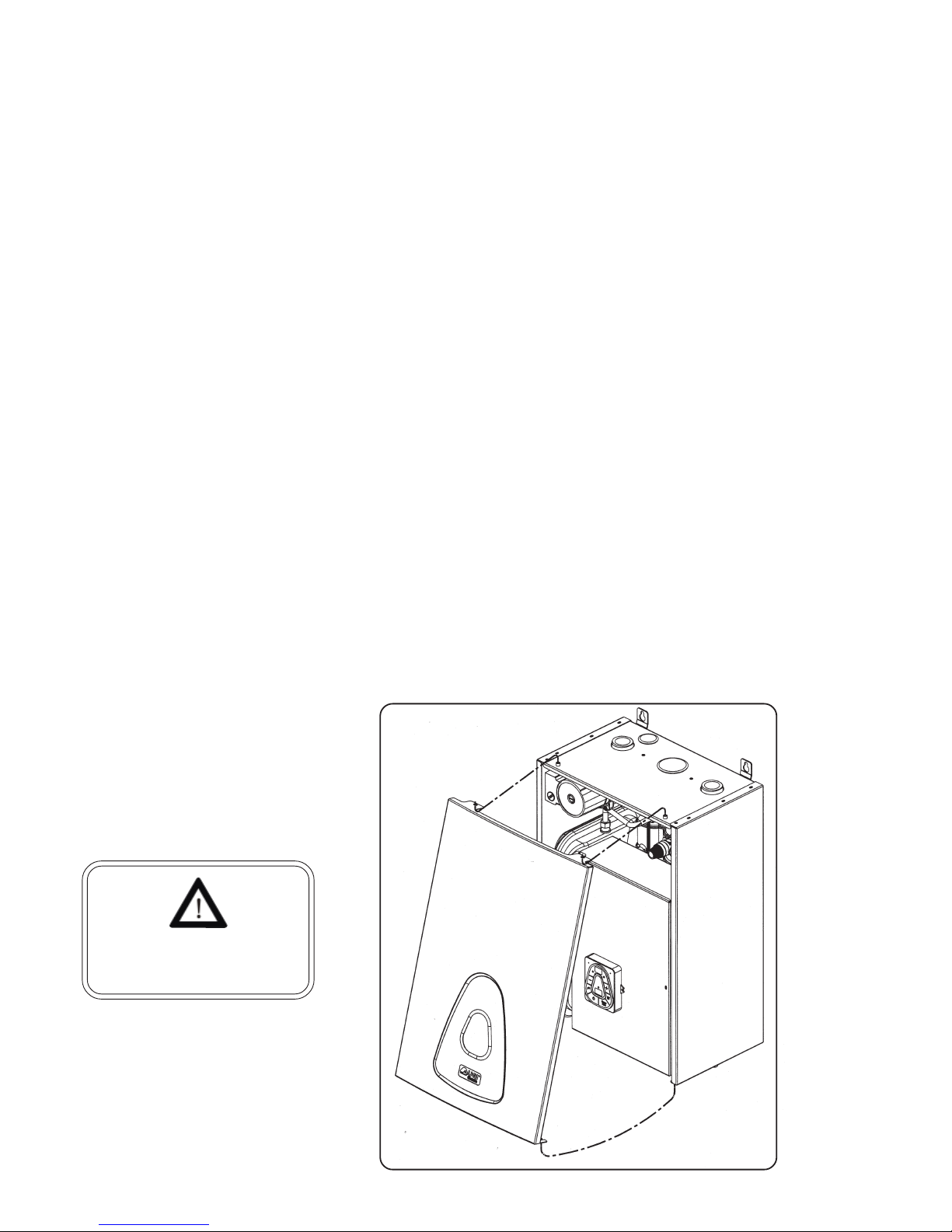
The boiler may be opened by unscrewing the bottom two bolts a couple of turns (they do not need to be
removed completely). The front cover may then be pulled out from the bottom and lifted off the two top pins.
Switch off the electricity
supply to the boiler before
opening the internal cover.
Page 13
Ascari MA12 -p. 13 -
2.4.2 - Electrical Compartment
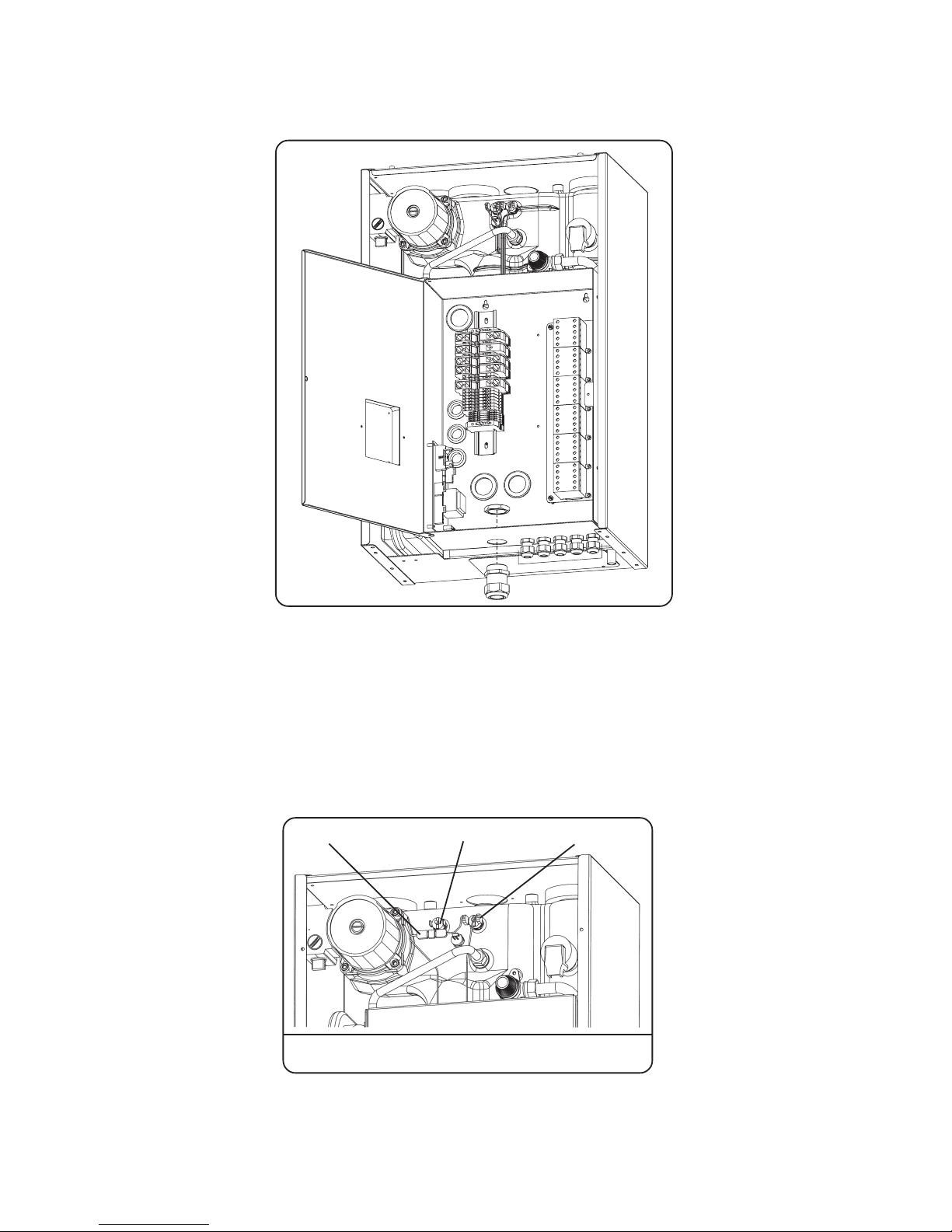
With the cover removed access to the electrical connections is achieved by undoing the screw of the electric
box. Once opened access is gained to the electrical connectors, for easy installation.
2.4.3 - Selecting Thermal cut-out
The thermal cut-outs are situated at the top of the boiler and may be selected during the installation by rerouting the electrical connections. The boiler is factory set with the 100oC cut-out selected for use with radiator
heating systems. If the Boiler is to be used with underfloor heating remove the connectors from the 100oC
sensor and connect to the 60oC sensor ensuring there is a good connection.
Where both underfloor and hot water cylinder are used, it is necessary to use the 100°C temperature cut-out in
the boiler and include a separate 60°C thermal cut-out for the underfloor heating circuit.
Thermal cut-out selection
(100deg C for radiators, 60deg C for underfloor)
60°C 100°CConnector
Page 14
Ascari MA12 -p. 14 -
2.5 - Installation Requirements
2.5.1 - Location
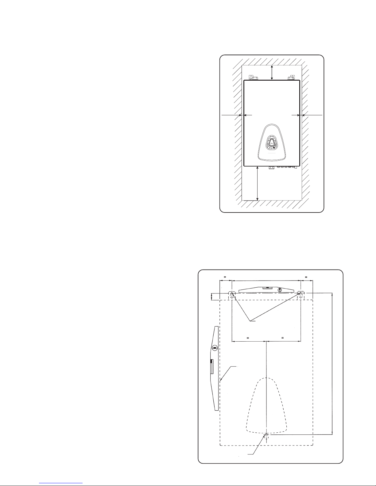
• The boiler must be located at least 300mm above any object
to allow the elements to be removed. At least 100mm is
required at the top of the boiler to allow for connection of
pipework.
• 10mm is required at the sides of the unit.
• The boiler must be mounted on an internal solid masonry
wall capable of withstanding the weight of the product when
full of water.
• Consideration should be given to the routing of electric cables
to the product and the wiring to a thermostat (if used).
• The location must be free from frost and excessive moisture.
10
10
300
100
2.6 - Installation
2.6.1 - Main Unit
•
Once the location of the boiler has been selected,
mark the hole positions as per figure 6.1 below. Use
a spirit-level to ensure the holes are aligned
correctly. Access to the bottom screw hole is
achieved by removing the bottom element plate.
• Once marked out, drill 8mm diameter holes and plug
with masonry plugs. Screw in high strength screws
to a depth that allows the inner face of the screw
head to protrude from the wall a distance to allow
the mounting plates at the rear of the boiler to
engage (approx 5mm).
• With suitable equipment or an assistant raise the
boiler to the fixing point and ensure each screw has
engaged into the mounting slots. T ighten the screws
to secure the boiler to the wall.
• Once fixed to the wall the boiler may be plumbed
into the central heating system.
Ø8 screw plug
Overall frame
pattern
Ø8 screw plug
300
29
605
Page 15
Ascari MA12 -p. 15 -
2.6.2 - Plumbing
2.6.2.1 - Radiators / Underfloor
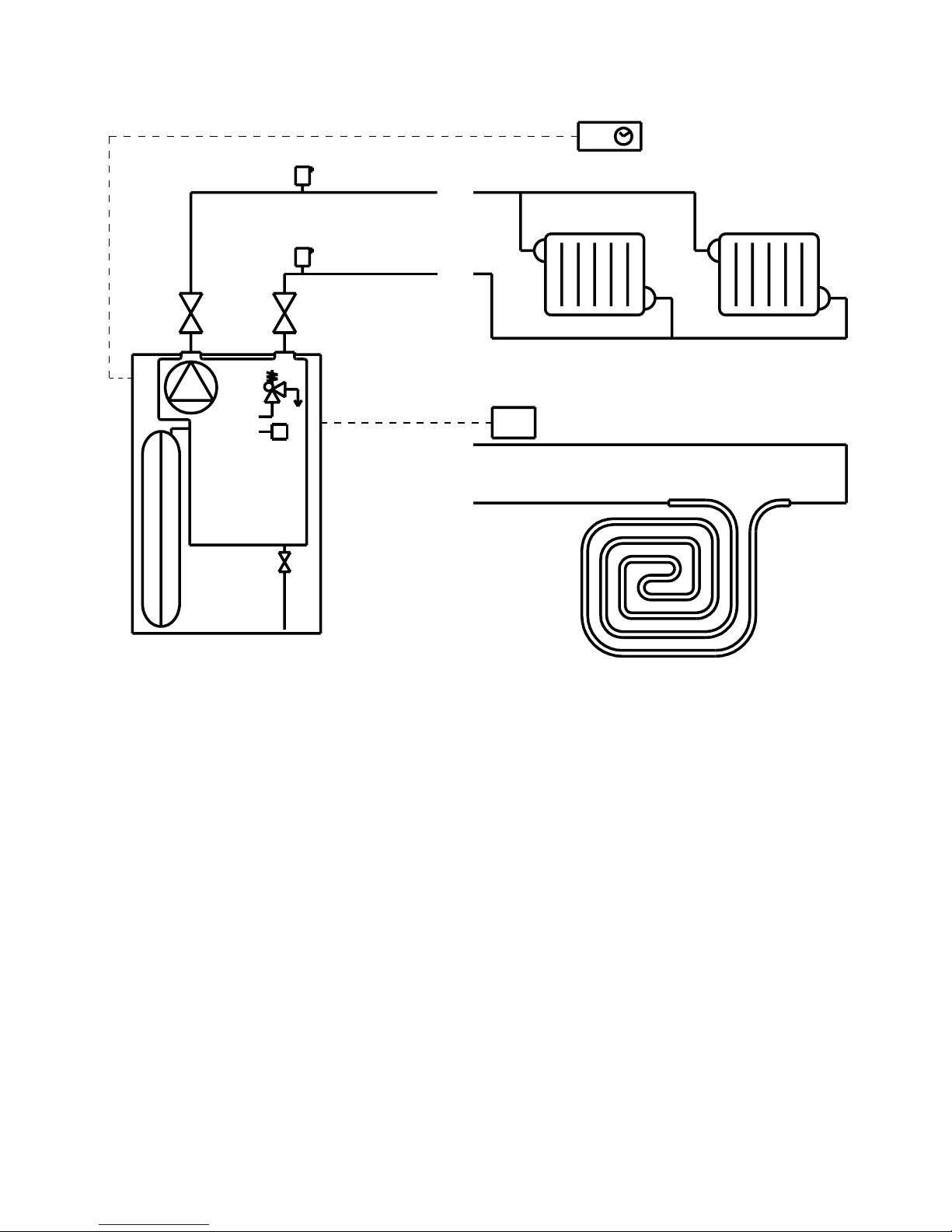
• Install the heating system bringing the flow and returns to the boiler location.
• The system should be flushed prior to connecting the boiler to remove all particles from the pipework. Do
not use the fitted pressure relief valve to flush the system as particles trapped in the valve will cause
incorrect valve operation.
• At least one air bleeding device should also be connected to the highest point of the plumbing system to
remove trapped air and ensure silent running of the heating system.
• If using radiators with Thermostatic Radiator Valves a bypass radiator must be fitted with lockshield
valves that will allow a flow of 350 litres/ hour.
• Service valves should be connected to the inlet and outlet of the boiler for easy maintenance.
• Although the boiler can operate without a room thermostat this is required for automatic adjustment of
boiler output temperature.
• Where underfloor heating is being used without hot water cylinder, the 60
o
C thermal cut-out must
connected in place of the factory selected 100
o
C device– see section 4.3.
• A drain cock is required to be fitted in the lowest part of the heating system to allow the system fluid to be
drained fully.
Room
thermostat
Radiators
Service
valves
Under Floor safety limiter
if used with hot water cylinder
Air bleeders
Pump
Expansion
Relief
Valve
Expansion
vessel
Underfloor heating
OR
Drain
tap
Page 16
Ascari MA12 -p. 16 -
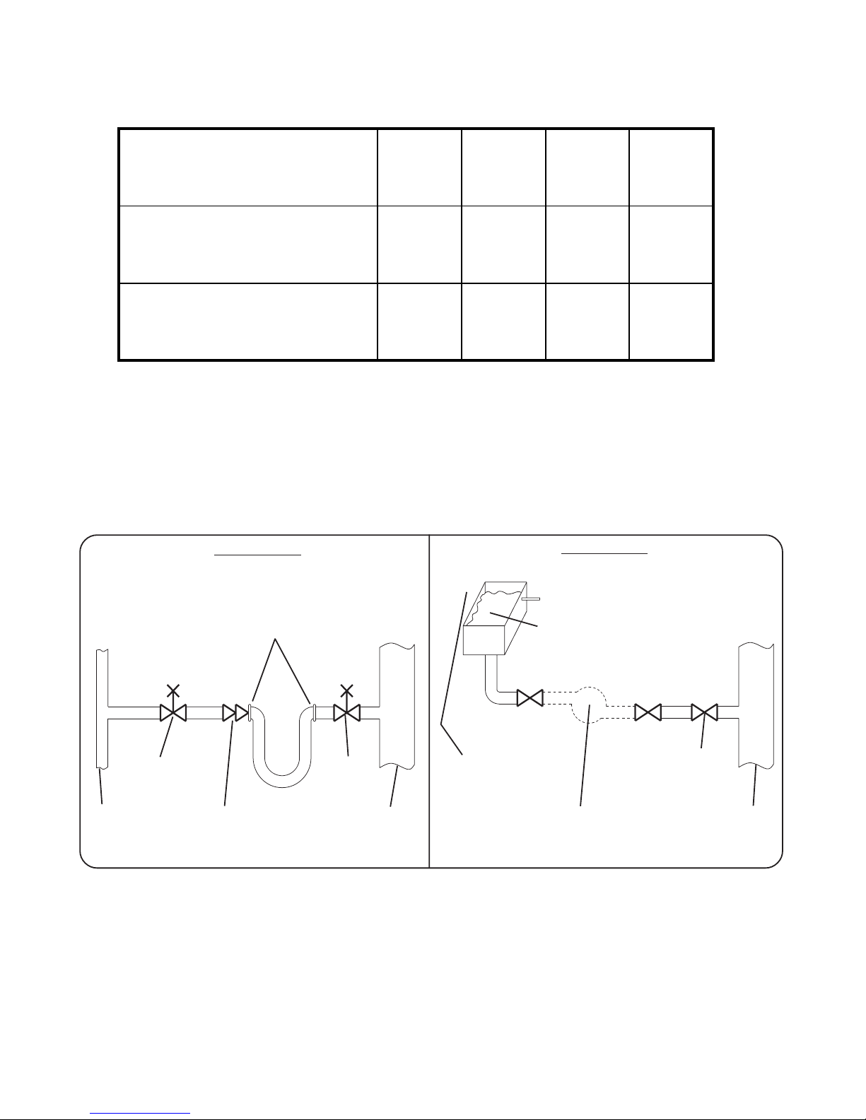
• A filling loop must be installed that isolates from the cold mains water supply from the heating system and
complies with the current building and water regulations in force at the time.
• The boiler incorporates an 8-litre expansion vessel which is suitable for heating systems as follows:
Initial System Pressure (bar) 0,50 0,75 1,00 1,50
Total Water in heating system (litres) 96 84 73 50
For larger systems
Multiply the volume of water
by these factors
0,0833 0,0930 0,1090 0,1560
2.6.3 - Filling Loop
This boiler is not fitted with a filling loop. Any filling loop being fitted should comply with the water supply (water
fittings) regulations 1999 Section G24.1 and G24.2. A filling loop should be fitted at some point to allow the CH
system to be filled.
Two types are shown below:
Stop
valve
Temporar y Flexible Hose
Connection
To be removed
immediately after filling
Mains
water
supply
Pressure Pump &
reducing valve
(if required)
Cistern &
Overflow
Mains
water
supply
Heating
System
Return
Double
check
valve
assembly
Stop
valve
Stop
valve
Heating
System
Return
METHOD B
METHOD A
F
F
Recommended and approved method for filling closed circuits in a house (R24-2a Water Regulations Guide)
Page 17

Ascari MA12 -p. 17 -
2.7 - Electrical
• Wiring external to the appliance must be in accordance with the current I.E.E Wiring regulations (BS 7671)
for electrical installation and any local regulations, which apply.
• With the boiler plumbed in, the electrical connections can be made
to the boiler:
• This appliance must be earthed!
• The Ascari boiler comes with cage-clamp connectors. These are operated using a 2.5mm x 0.4mm blade
screwdriver for accessory terminals and 3.5mm x 0.5mm blade screwdriver for power terminals.
• The boiler should be permanently connected to the electricity supply, direct from a 63A fused supply on the
consumer unit via a double pole linked switch with minimum contact gap of 3mm. No other appliances
should be powered from this supply.
• The number and cross-section of connector is mandatory 3 x 16² (phase + neutral + earth) (see § 2.15
«connection to the electricity supply»)
• To connect a wire, insert the blade of the screwdriver into the opening located just above or below the
central mark of the terminal block and pivot the blade towards the centre. The wire may then be inserted
into the cage and the screwdriver blade removed (see § 2.14 «Power terminal»).
• ROOM THERMOSTAT - The no voltage connections of a room thermostat may be connected to terminals
1 (common contact) and 2 (Normally Open contact) of the boiler (please check compatibility with thermostat
manufacturers installation instructions), routing the cable through the smaller cable entry points. If using a
non-programmable room thermostat it is recommended that the no-voltage switched contacts of a sep arate
timer / programmer be connect in series with the room thermostat to terminal 2 of the boiler. WARNING- a
switched live must not be connected to the boiler terminals.
• If used the cylinder thermostat normally open contact (240V) should be connected to terminal 25 of the
boiler’s electrical connectors ( see section Boiler electrical connections)
• The power supply cable (3x16²) should be routed through the large cable entry point at the bottom of the
boiler. If desired the cable entry may be moved to the top of the boiler by removing the self sealing nut from
the bottom to the top entry point.
• The Earth wire should be connected to the top terminal marked with the Earth symbol.
• The Neutral wire should be connected to the large terminal marked ‘N’.
• The live wire to the large terminal labelled PH.
• Do not switch on the electricity supply until asked to do so in the Commissioning and Testing section.
• As a minimum it is recommended that a room thermostat be inst alled to control the appliance. Thermost atic
radiator valves may be fitted to the system, however they must not be fitted in the room where the room
thermostat is fitted. There must be at least one radiator installed with lock shield valves that should not be
closed and will allow 350litre/hr circulation. Further guidance can be obtained from the Domestic Heating
and Hot Water Guide to the building regulations.
Page 18
Ascari MA12 -p. 18 -
2.7.1 Power selection
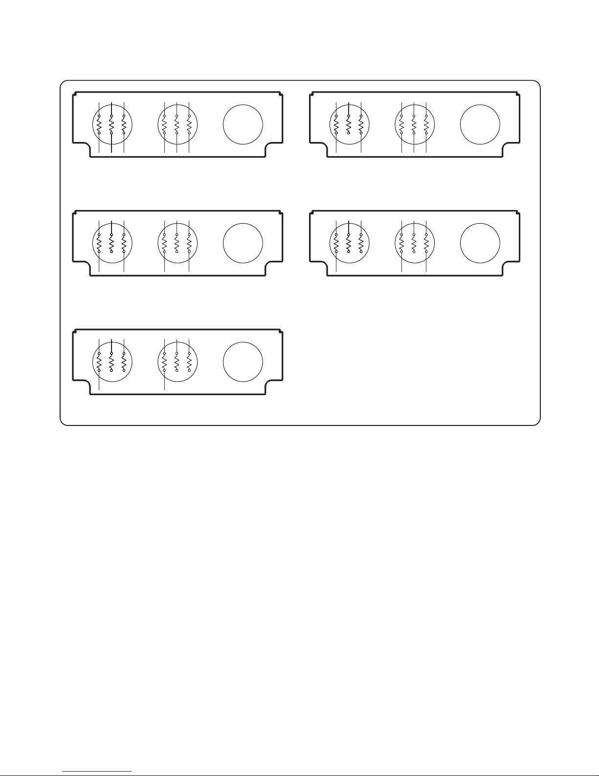
The boiler is supplied as a 12Kw modulating boiler but can be reduced to 10, 8, 6 or 4kw by disconnecting
individual elements.
* Remove blue connectors between power terminal and elements
according to drawing.
ex-work
R : Red
Bl : Black
W : White
B : Blue
12 kW 10 kW*
8 kW* 6 kW*
4 kW*
R
BBBB
WBl WBlR
BB
R
BBB
WBl WBlR
BB
R
BBB
WBl WBlR
B
RBBWBl WBlR
B
RBBWBl WBlR
View from bellow
2.8 - Commissioning & Testing
Water Treatment, Cleansing and Flushing the Heating System
NOTE: British Standard BS7593: 1992 stresses the importance of cleansing and flushing of the system to
ensure it continues to run efficiently with the minimum of maintenance necessary. Halstead Boilers fully support
this professional approach and recommend that the system is cleansed with an effective chemical cleanser and
protected long term with a suitable inhibitor. Such products are available from Fernox and Sentinal.
• Check the pressure of the expansion vessel, this should be factory set to 1bar (0.1MPa).
• The heating system should be filled using the approved installed filling loop. Ensure all radiator valves are
open. The initial system pressure when cold should be between 1.0 (0.lMPa) and 1.5bar (0.15MPa).
• Once filled check the system for leaks.
• Open the drain cock and drain the system fully.
Page 19

Ascari MA12 -p. 19 -
• Refill the system from the filling loop, to a pressure between 1-1.5bar (0.1-0.15MPa) and operate the
pressure relief valve manually to check that water runs away correctly, and that the valve closes correctly.
• Top up the system to 1.0bar (0.1MPa).
• Disconnect the system from the filling loop.
• Check the electric connections and that all covers etc. have been replaced. Turn on the electricity supply to
the boiler and allow the unit to do its self diagnosis. Refer to § 2.24 if a fault is displayed.
• Use ethylene glycol only with incorporated corrosion inhibitor. Glycol ratia must be under 10%.
2.9 - Boiler Configuration
Once the boiler has initialised the feature options can be selected (see quick reference guide for options):
Press – and + together for 3 seconds to enter the selection menu. With reference to § 2.21 the top display
should show a flashing 01. Use the +/- keys to select the parameter to be changed and the tap or radiator keys
to change the setting of any selected parameter:
01 This setting should always be set to 1.
02 Select the maximum temperature of the water circulating in the heating circuit.
03 Select the minimum temperature of the water circulating in the heating circuit.
04 Select 1 if oprating from a switched live or if of room thermostat is installed and connected to
the boiler.
05 If 04 has been set to 1 this setting should also be set to 1.
06 If 04 has been set to 1 the boiler can automatically adjust the water temperature in the heating
circuit according to actual heat-up times of the property , overriding the minimum and maximum
water temperature settings. If this facility is required select 1, otherwise set 0.
07 This option should be set to 0.
08 n/a
09 n/a
10 n/a
11 The boiler can delay the switching on and off of the elements to provide a smooth power on-
off gradient and the number of on-off cycles in a short period. The delay between switches
operating can be set from 1 to 6 minutes. (default is 2 min)
12 Select 0 for central heating or floor heating only. (default is 0)
Select 1 if boiler connected to indirect hot water cylinder.
13 This setting should always be set to 0.
14 n/a
Press + & - together for 3 seconds to exit the set-up menu.
Page 20

Ascari MA12 -p. 20 -
2.9.1 Automatic/ Manual Operation
The boiler must be set to Manual operation as follows:
Press and hold the Auto/Man button for 3 seconds. The display will show Au or Man, press the Auto/Man button
again for a short period to toggle the display so that it shows Man. With the correct display showing, press and
hold Auto/Man for 3 seconds to return to normal operating mode.
2.10 - Pump Speed
The boiler is factory set at pump speed 3, for lower pump speeds the selector in the centre of the pump may be
turned to 1 or 2 using a large flat bladed screwdriver.
2.11 - Troubleshooting
The boiler has many selectable options. Please ensure the correct selections are made for the type of installation
you have made. If you have selected the use of a room thermostat, or hot water cylinder, the boiler will not
operate until these devices are connected.
• The boiler indicates a boiler fault by flashing all segments of the temperature display.
Please call the Dimplex Customer Service department – see Servicing section.
• 2 FLASHING SEGMENTS in front of bar – indicate the system pressure has fallen below the minimum
operating pressure.
• check if water has discharged from the pressure relief valve. If so call a Dimplex service agent.
• check for leakage in the system.
Once the fault has been cleared the boiler will turn on again if the system is filled and pressurised to over 0.5
bar.
2.12 - Ser vicing
It is recommended that the Boiler be installed and serviced regularly by a Dimplex service agent to ensure
continual trouble-free operation. For details of service agents in your area please contact:
Glen Dimplex UK Limited
Millbrook House
Grange Drive
Hedge End
Hampshire
SO30 2DF
Dimplex Customer Services on 0870 727 0101
Page 21
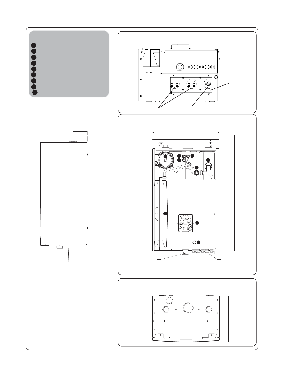
Ascari MA12 -p. 21 -
Decoding
1 - 3 speed pump
2 - 8 liters expansion vessel
3 - 3 bar safety relief bleeder
4 - La ck of water sensor
6 - 60°C safety limitator
7 - 100°C safety limitator
8 - Boiler's sensor
9 - Control pannel
11 - Fuse
2.13 - Dimensions - Hydraulic connections
D = Heating outflow 1" female nut (26/34)
R = Heating backflow 1" female nut (26/34)
(Trapdoor to access elements removed)
405
300
619
Power wire entry
Accessories
connection entries
Side view
Front view
Bottom view
Top view
Safety relief drain
Ø15
87,5
29
Elements
fastener
Heating elements
259
280
81
DR
1
6
7
3
4
2
8
9
11
Drain tap
Page 22
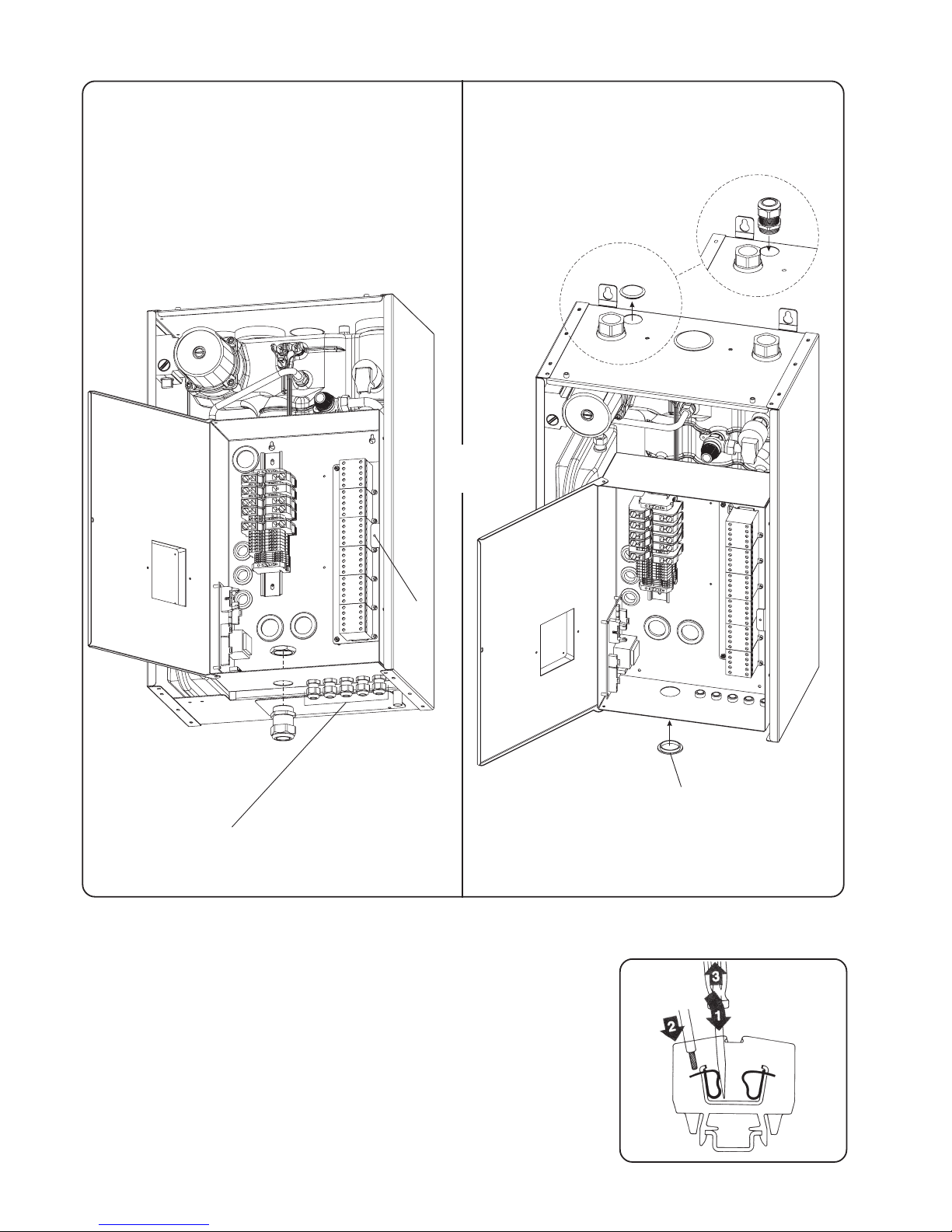
Ascari MA12 -p. 22 -
1:Introduce the blade of the driver into the opening located just
above or bellow the mark with a slight pivoting move to center.
2:Introduce the connector's terminal inside the cage.
3:Remove the screwdriver
2.14 - Power ter minal
Connections are cage-clamp terminals, to be used as to follow :
- For accessories terminals use a 2,5 x 0,4mm blade screwdriver
- For power terminal use a 3,5 x 0,5mm or 5,5 x 0,8mm blade
screwdriver.
Screw A
5 self-sealing nuts for accessories connections
(Ambience thermostat, outside and/or Domestic Hot
Water sensor and remote cut-out)
Put the self-sealing nut (supplied with the boiler) for
connection to mains from the bottom of the casing.
or
Put the self-sealing nut (supplied with the boiler) for
connection to mains from the top of the casing. In
this case remove the plastic cap and close the hole
below casing using same.
Plastic cap moved from top
to bottom
Page 23
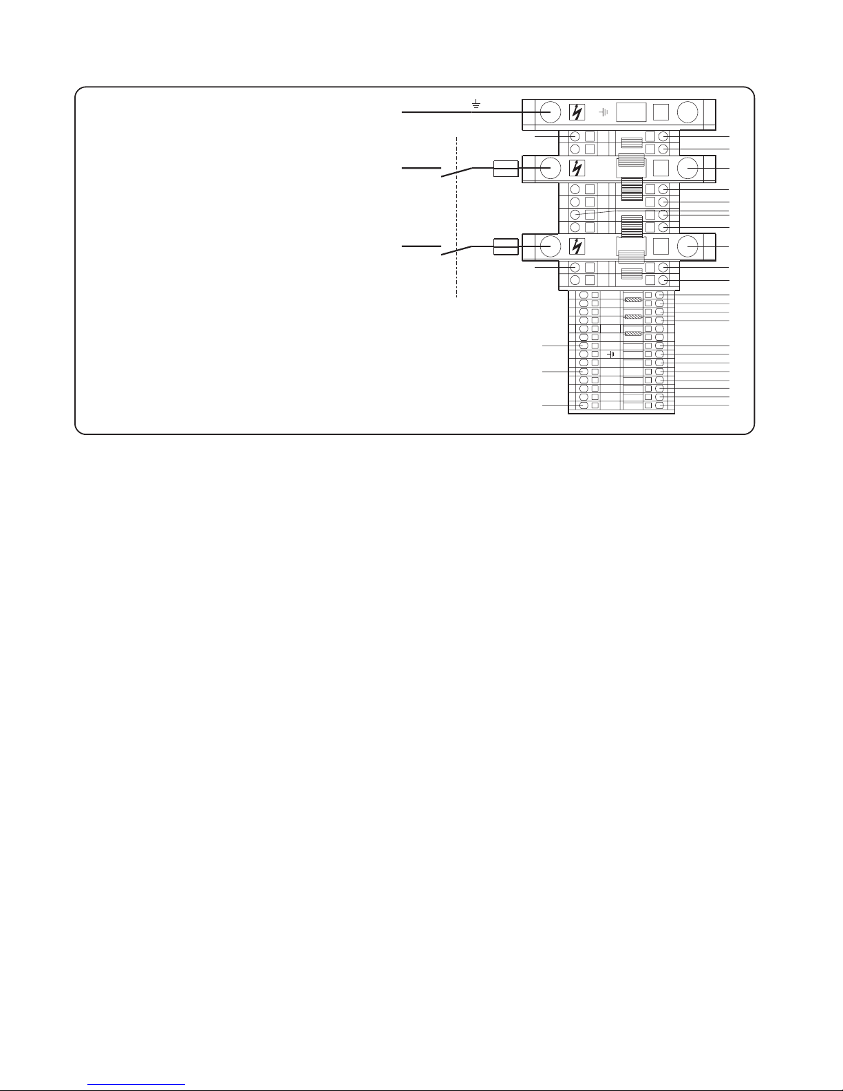
Ascari MA12 -p. 23 -
2.15 - Connection to the electricity supply
I: 63A fused supply on the consumer unit
via a double pole limited switch with
minimum contact gap of 3mm.
N
OTE : Stripped length of wires between 16 and 17mm
Neutral 16²
Phase 16²
Ground 16²
I
Page 24
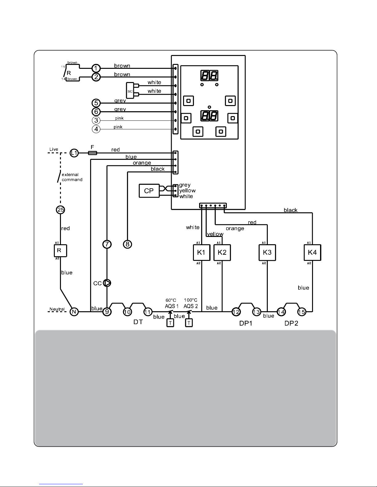
Ascari MA12 -p. 24 -
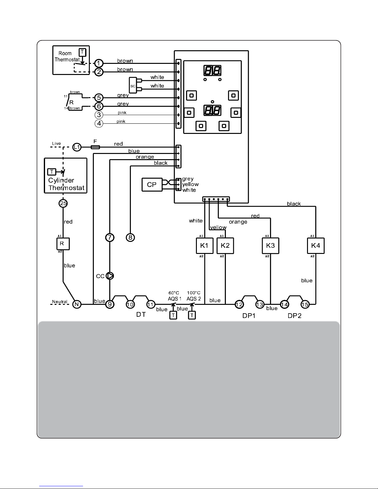
2.16 - Regulation circuit drawing
2.16.1 - Operating from a switched live
L1 : Live
N : Neutral
F : 4A fuse size 5 x 20
C1 : Electronic card with display
CC : 3 speed pump
SC : Boiler's sensor
AQS1 : 60°C safety limitator with manual reset
AQS2 : 100°C safety limitator with
manual reset
K1 to K4 : 20A power breakers
DT : Total cut-out (remove the bridge)
DP1 & DP2 : Partial cut-out (remove the
bridge)
R : External command relay
Decoding :
Page 25
Ascari MA12 -p. 25 -
2.16.2 - Direct room thermostat connections
and direct cylinder thermostat
L1 : Live
N : Neutral
F : 4A fuse size 5 x 20
C1 : Electronic card with display
CC : 3 speed pump
SC : Boiler's sensor
AQS1 : 60°C safety limitator with
manual reset
AQS2 : 100°C safety limitator with
manual reset
K1 to K4 : 20A power breakers
DT : Total cut-out (remove the
bridge)
DP1 & DP2 : Partial cut-out (remove the
bridge)
R : External command relay
Room thermostat : Direct room thermostat no-
volt normally open contacts
Cylinder thermostat : External command from
direct cylinder thermostat
(normally open contact
240V)
Decoding :
Page 26
Ascari MA12 -p. 26 -
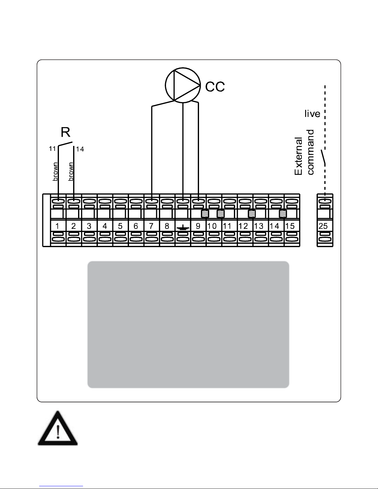
2.17 - Control accessories wiring
2.17.1 - Operating from a switched live
1 - 2 : External command relay contact
3 - 4 : n/a
5 - 6 : n/a
10 - 11 : Total cut-out DT (remove the bridge) and / or 65°C
heating floor safety limitator (mandatory) with
manual reset.
See § 1.3.1.
12 - 13 : Partial cut-out DP1 (remove the bridge)
14 - 15 : Partial cut-out DP2 (remove the bridge)
25 : External command of switched live (use phase 230V
common to the boiler on pin L1)
• Connectors will be of electrolitic quality brass (no corrosion of stripped ends at connection).
• Never use telephone wire (cross-section of sub-connectors too thin and easy breakable at
connections points).
• Cross-section of connectors must be between 0,5 and 1mm².
Page 27
Ascari MA12 -p. 27 -
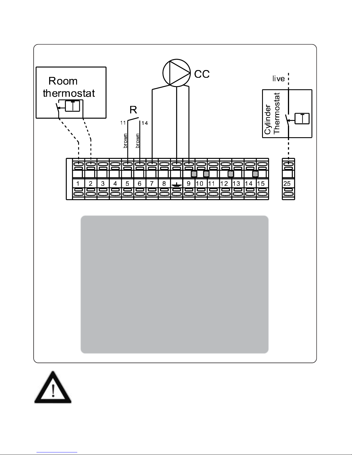
2.17.2 - Direct room ther mostat connections
and direct cylinder ther mostat
1 - 2 : Direct room thermostat connections
3 - 4 : n/a
5 - 6 : The brown wires should be removed from terminals
1 and 2 and be placed into terminals 5 ans 6
respectively
10 - 11 : Total cut-out DT (remove the bridge) and / or 65°C
heating floor safety limitator (mandatory) with
manual reset.
See § 1.3.1.
12 - 13 : Partial cut-out DP1 (remove the bridge)
14 - 15 : Partial cut-out DP2 (remove the bridge)
25 : External command from direct cylinder thermostat
(use phase 230V common to the boiler on pin L1)
• Connectors will be of electrolitic quality brass (no corrosion of stripped ends at connection).
• Never use telephone wire (cross-section of sub-connectors too thin and easy breakable at
connections points).
• Cross-section of connectors must be between 0,5 and 1mm².
Page 28
Ascari MA12 -p. 28 -
Légende :
AQS 1
60°C
white
yellow
grey
GND
OUT
+Vdc
230 V / 12 V
adaptator
6
5
4
3
2
1
black
red
yellow
white
pink
grey DHW sensor
pink Outside sensor (S.Ext)
grey
white
white
boiler's sensor (SC)
ambience thermostat (TA)
red
blue
black
orange
F
11
10
9
4
5678
12
13
14
15
NNN
PH
PH
PH
PH
red
red
black
black
white
white
TT
blue
AQS 2
100°C
blue
red
black
white
blue
blue
(1)
: In optionnal
CC : 3-speed pump
DHW sensor : Domestic Hot Water Safety limitor
SC : Boiler's sensor
PH : Phase
N : Neutral
F : 4A fuse size 5 x 20
C1 : Electronic card with display
NPH
brown
brown
blue
DHW pump C.ECS
Heating pump CC
230V power
pressure sensor power
pressure sensor connect.
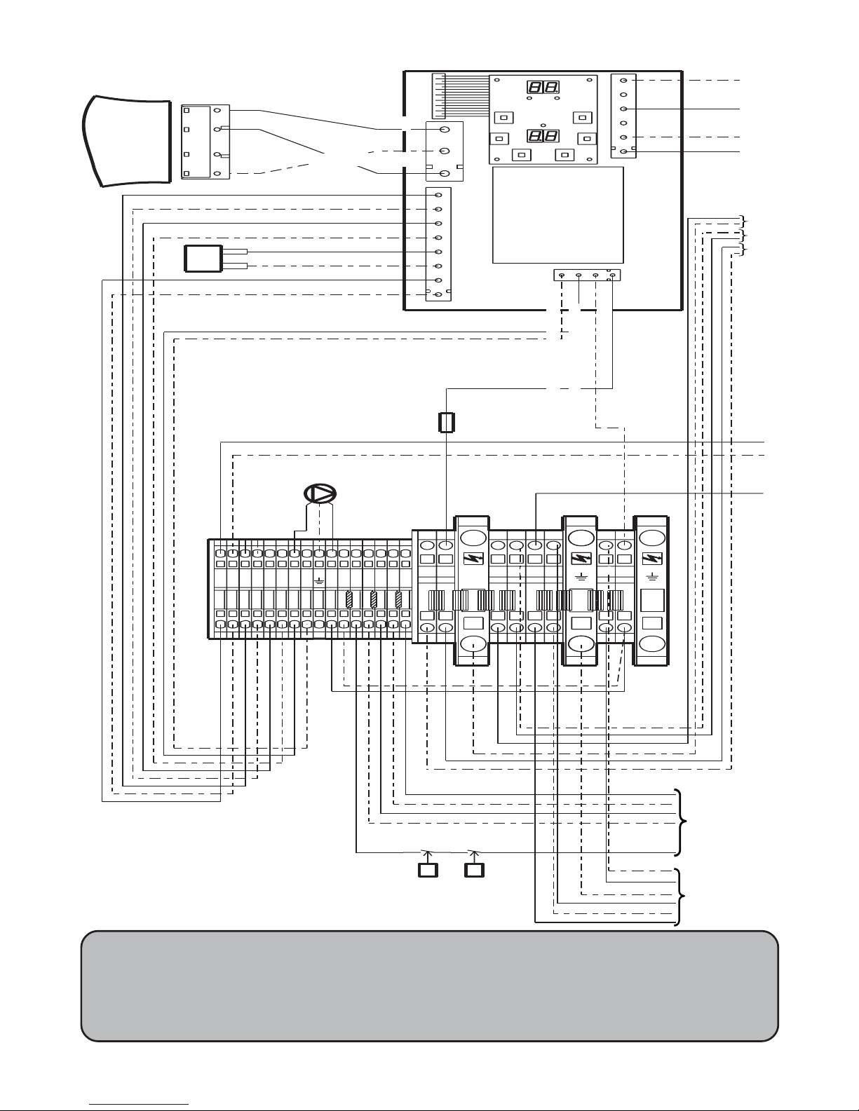
2.18 - Wiring dia gr ams
CC
brown
green
yellow
blue
external command relay contact
GND 1
+Vdc 2
3
OUT 4
SC
1
3
2
brown
brown
Page 29
Ascari MA12 -p. 29 -
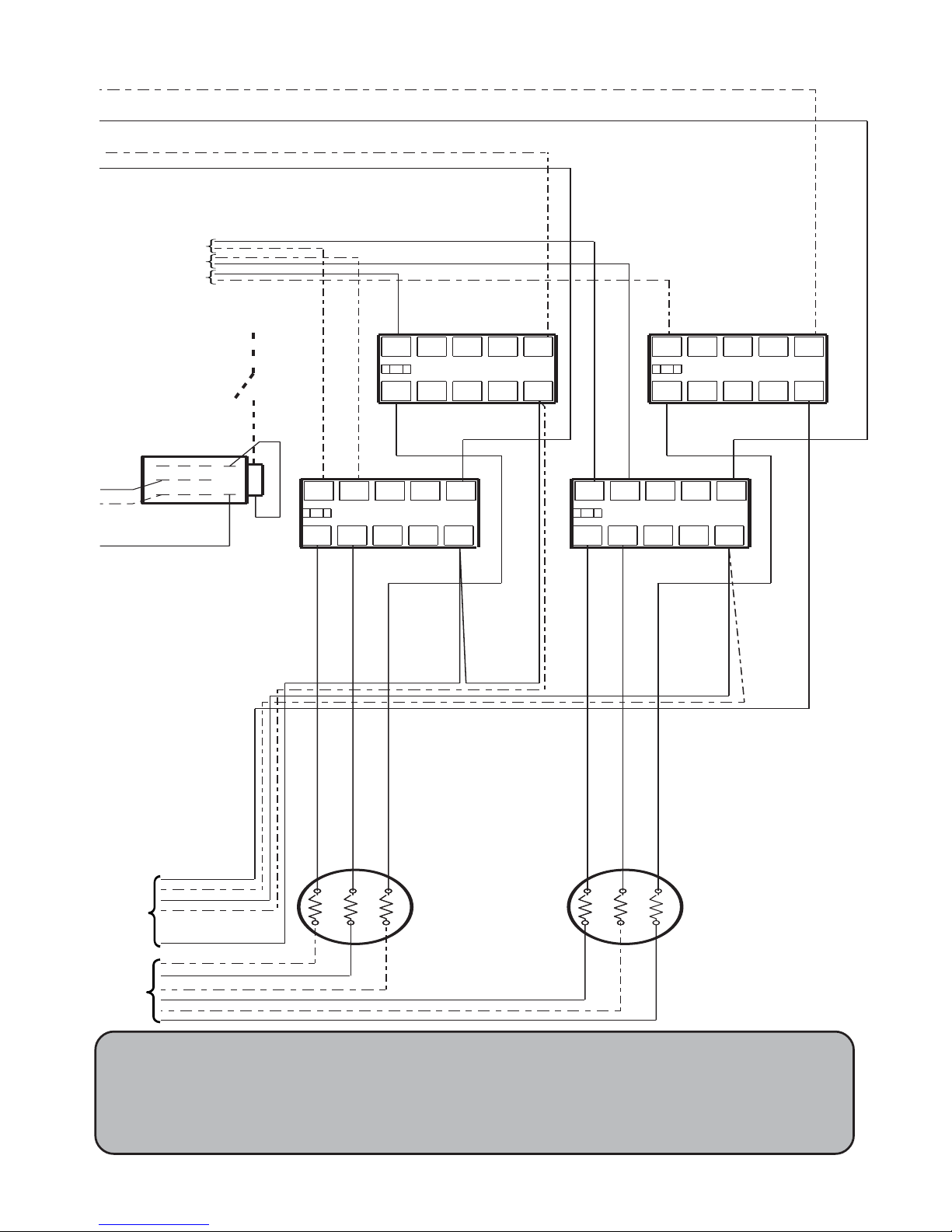
AQS1 : 60°C Safety limitor with manual reset
AQS2 : 100°C safety limitor with manual reset
Légende :
L2
L3
L1
L4 A1
A2
T4
T3
T2
T1
K2
L2 L3
L1 L4 A1
A2
T4T3T2
T1
K4
L2 L3
L1
L4
A1
A2
T4
T3
T2
T1
K1
L2
L3
L1
L4
A1
A2
T4T3
T2
T1
K3
red
balck
white
white
red
black
white
red
white
yellow
white
black
blue
blue
blue
red
black
red
balck
blue
T1 T2
bleu
bleu
red
black
white
brown
brown
blue
black
red
yellow
white
12
25
R
a2
a1
11
14
red
K1 to K4: 20A power breakers
T1 & T2 : 6kW heating elements
live
External
command
Page 30
Ascari MA12 -p. 30 -
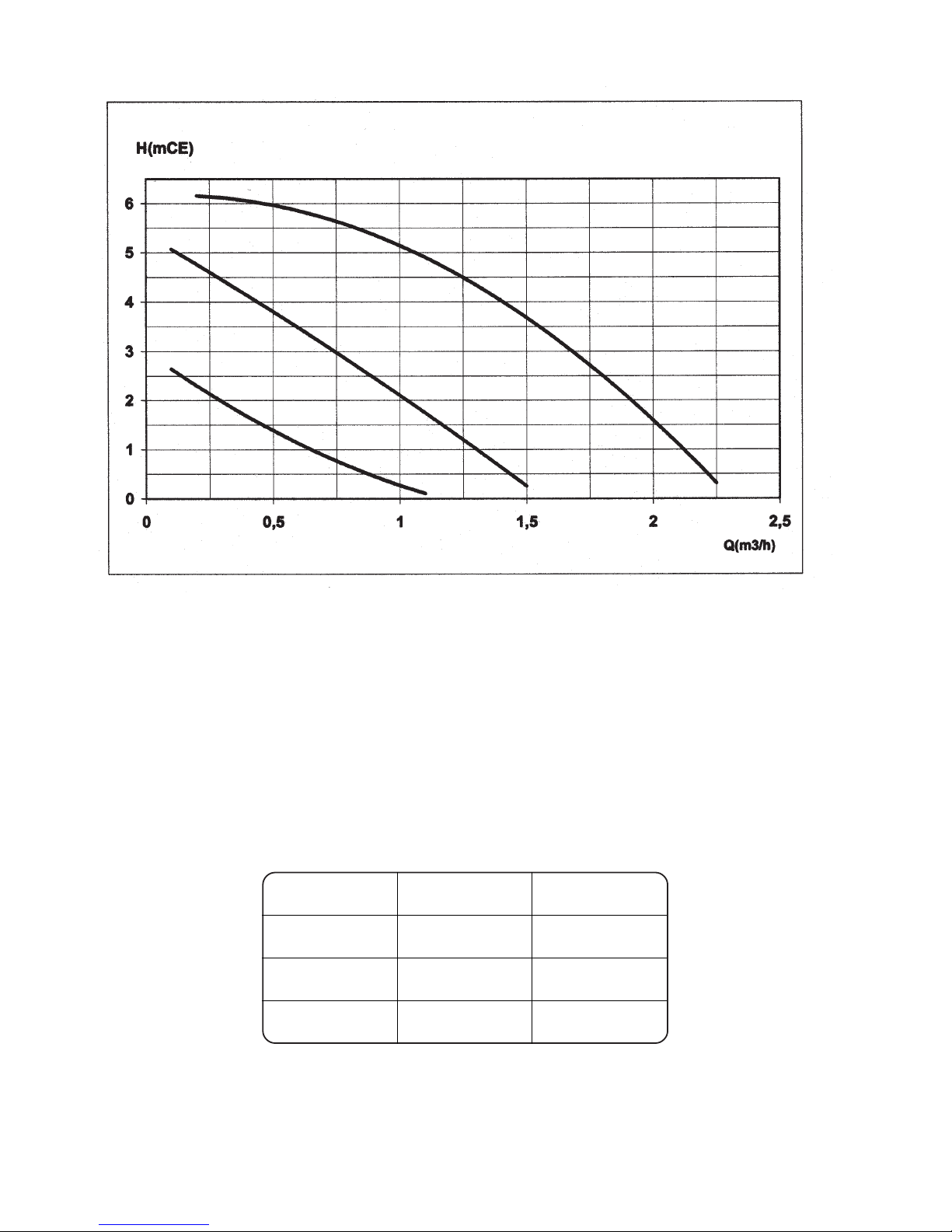
3 speed (I, II et III) water pump for adjustment to operating needs, depending on insulation and circuit
Electric datas
II
II
I
IIIIII
IIIIII
III
IIII
IIII
II
Speed
Nominal
output (W)
Nominal
inten s ity (A)
III
90 0,40
II
67 0,30
I
47 0,20
The boiler is factory set at pump speed 3, for lower pump speeds the selector in the centre of the pump may
be turned to 1 or 2 using a large flat bladed screwdriver.
2.19 - 3 Speed water pump
Page 31
Ascari MA12 -p. 31 -
bar
° C
Auto
Manu
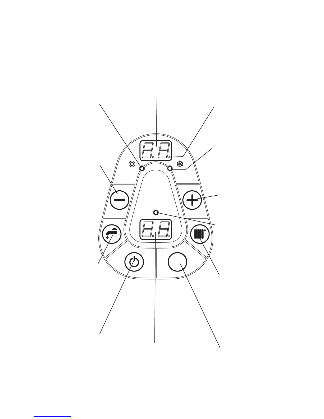
Usual operating functions
Boiler's temperature display in °C.
When the boiler is off and the two
middle horizontal LEDs on, antifrost
protection is operating.
(flashing in case of sensor failure)
(Glittering • displays normal
operating)
Winter mode green LED
Operating display red LED
Used to increase
temperature during settings
(instant touch)
Used to enter requested
heating temperature menu
(instant touch) or start the
winter mode (heating and
DHW) (press 3 sec.)
Must be set to manual
Used to choice manual or
automatic operating (see
§2.9.1)
Pressure display in bar.
Boiler stops automatically below 0,3 bar
with automatic reset over 0,5 bar.
(0,2 blinking displays a pressure loss -
other value flashing displays a
pressure sensor failure)
On/Off switch (with
automatic anti frost
protection for DHW and
heating circuits) (instant
touch)
Hot Water selection (n/a) or
start the spring mode DHW
(press 3 sec.)
Used to decrease
temperature during settings
(instant touch) or cancel
(press 3 sec)
Summer mode green LED
2.20 - Control pannel description
Page 32

Ascari MA12 -p. 32 -
For fitter's use only.
The regulation must be adjusted according the use of the boiler.
• Press
and (3 sec) to start setting menu for 4 minutes.
• Parameter #
starts blinking in front of "°C"
• Press
or (instant touch) to select next parameter, i.e °C, ... until °C
• To start setting the displayed parameter press
or (instant touch).
• The parameter value, i.e
starts blinking in front of "bar".
• Press
or (instant touch) to change setting.
• Press
or (instant touch) to confirm setting and return to setting menu.
• Press
and (3 sec) any time to exit the setting menu.
2.21 - Regulation settings
Page 33
Ascari MA12 -p. 33 -
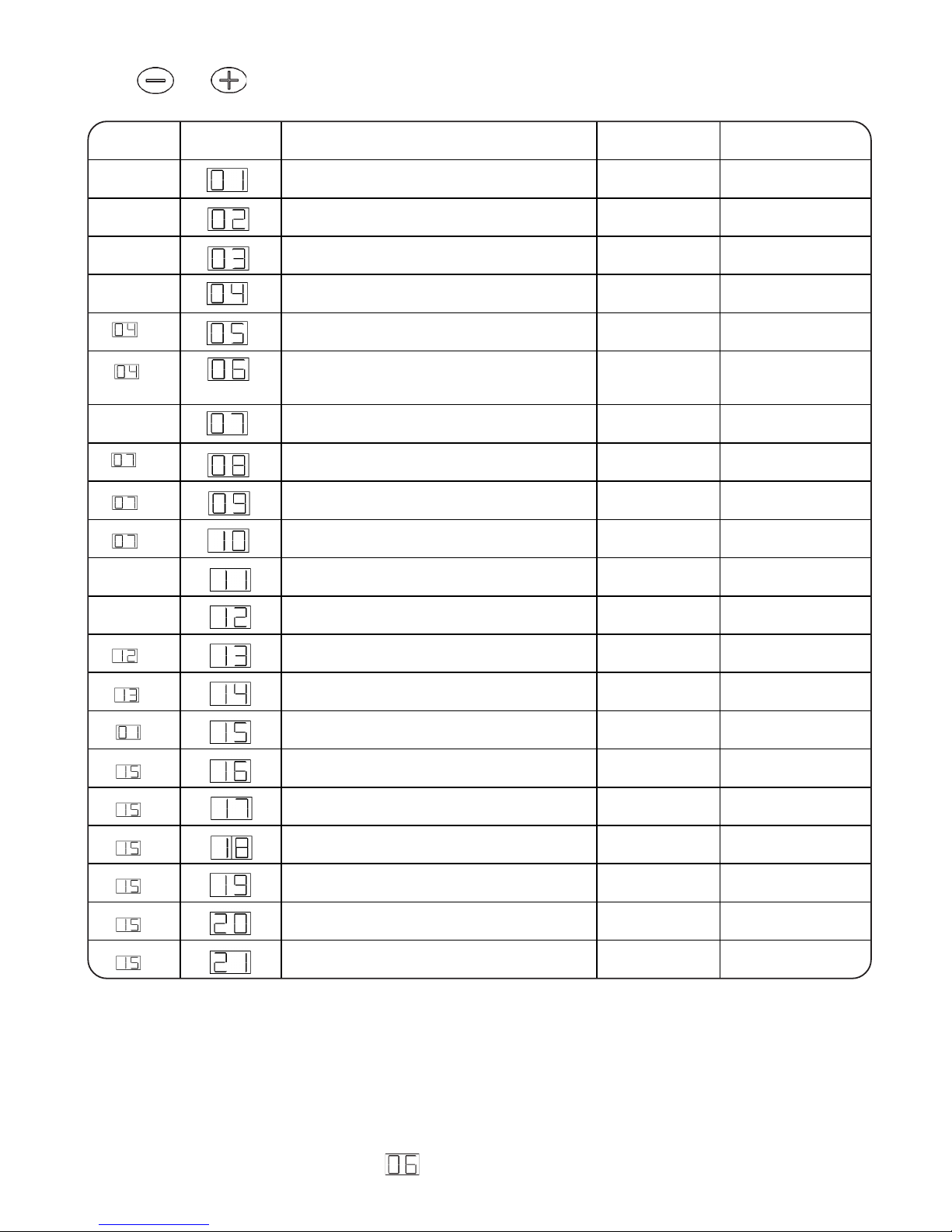
Available if Paremeter # Description Setting range Ex-word settings
Electric boiler (no = O ; yes = 1) 0 or 1 1 mandatory
(1)
Maximum requested boiler's temperature
(TCMA)
21 to 80°C 75°C
(1)
Minimum requested boiler's temperature
(TCMI)
21 to TCMA °C 50°C
External command installed (switched live or
room thermostat (no = O ; yes = 1)
0 or 1 1
si = 1
Heating circuit pump linked to external
command (no = O ; yes = 1)
0 or 1 1
si = 1
Autoadaptability or automatic adjustment of the
requested temperature (no = O ; yes = 1)
0 or 1
(2)
1
Outside sensor (no = O ; yes = 1) 0 or 1 0 mantatory
si = 1
(1)
Maximum outside temperature (TEMA) n/a 11 to 25°C 20°C
si = 1
(1)
Minimum outside temperature (TEMI) n/a -30 to +10°C -5°C
si = 1
A
utomatic tipping up summer mode
(no = O ; yes = 1)
n/a 0 or 1 0
Operating postponement
1 to 6 min
(3)
2 min.
Indirect Hot Water production
(no = O ; yes = 1)
0 or 1 0
si = 1 DHW sensor (no = O ; yes = 1) 0 or 1 0 mantatory
si = 1
Legionnaires disease free mode (off)
(no = O ; yes = 1)
n/a 0 or 1 0
si = 1
Engaging of 6 power stages
(no = O ; yes = 1)
0 or 1 0
si = 0
Engaging stage 1
(no = O ; yes = 1)
0 or 1 1
si = 0
Engaging stage 2
(no = O ; yes = 1)
0 or 1 1
si = 0
Engaging stage 3
(no = O ; yes = 1)
0 or 1 0
si = 0
Engaging stage 4
(no = O ; yes = 1)
0 or 1 1
si = 0
Engaging stage 5
(no = O ; yes = 1)
0 or 1 0
si = 0
Engaging stage 6
(no = O ; yes = 1)
0 or 1 1
PARAMETERS LISTING
Press and during 3 sec to access parameters menu.
(1)
: See § 7 to set the heating diagram according to 4 paremeters (TCMA, TCMI, TEMA and TEMI)
(2)
: Prohibited when using a scheduled external command
(3)
: Depending on water flow rate and volume inside the heating circuit, the boiler might start at very short
intervals with wear and tear resulting. To reduce the number of cycles, increase postponement.
NOTE : To reset autoadaptability, zero parameter # , then set value to 1.
Page 34

Ascari MA12 -p. 34 -
2.22 - Operating
Display in front of symbol "°C" means the boiler is off, connected to power supply, with anti frost
protection operating (boiler starts automatically when the boiler's temperature or the Domestic Hot Water
temperature turns below 5°C).
Press
to turn the boiler On or Off.
2.22.1 - Automatic / Manual Operation
The boiler must be set to Manual operation as follows :
Press and hold the Auto/Man button for 3 seconds. The display will show Au or Man, press the Auto/Man
button again for a short period to toggle the display so that it shows Man. With the correct display showing,
press and hold Auto/Man for 3 seconds to return to normal operating mode.
2.22.2 - Requested heating temperature setting in manual mode
Press to display the requested temperature blinking in front of symbol "°C".
Press or to increase or decrease the requested temperature between TCMI and TCMA.
(see § 2.21).
Press to confirm setting.
2.22.3 - Summer / Winter shift
(Available in manual mode only (see § 2.22.1 above)
Press during 3 sec to start the summertime mode and lit Summertime LED;
Press during 3 sec to start the wintertime mode and lit the Wintertime LED.
Page 35
Ascari MA12 -p. 35 -
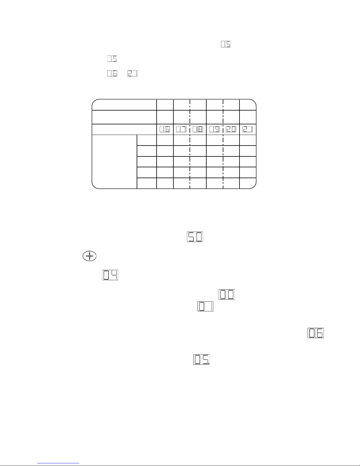
2.22.5 - Temperatures display
During normal operating the boiler's temperature, i.e : is on display in front of symbol "°C".
1st pressure on
displays the ambience sensor display.
Parameter #
is displayed in front of symbol "°C"
external command status is on display in front of "bar" :
for boiler's run not requested
for boiler's run requested
2nd (or 1st if no external command) pressure displays the temperature correction in°K (parameter #
in front of symbol «°C» (see § 2.21 to zero this correction).
Temperature correction can be read on bottom display i.e.
with a glittering LED down right the display
if a negative value (-5°C in this example).
2.22.4 - Programming the maximum output setting of the boiler
The boiler is delivered with a maximum output of 12kW (parameter = 1).
Set the parameter = 0
Set parameters of
to to requested value according following tables to adjust the maximum
output of the boiler :
123456
4 kW 2 kW 0 kW 4 kW 0 kW 2 kW
12 kw110101
10 kW100101
8 kW100100
6 kW100001
4 kW010001
Power stage #
Power stage value
Parameter number
Parameter value
to obtain the
requested
maximum output
(0 = no ; 1 = yes)
Page 36
Ascari MA12 -p. 36 -
2.24 - Failures display
The boiler has many selectable options. Please ensure the correct selections are made for the type of
installation you have made. If you have selected the use of a room thermostat, or hot water cylinder, the
boiler will not operate until these devices are connected.
The boiler indicates a boiler fault by flashing all segments of the temperature display.
In case of boiler's temperature failure, all 14 LEDs
in front of symbol "°C" are blinking. The boiler is
off, the water pump still running.
In case of Domestic Hot Water sensor failure (if parameter
= 1), all 14 LEDs in front of symbol
"°C" are blinking. The boiler is automatically restricted to heating.
In case of outside temperature sensor failure (if parameter
= 1 or if used to automatic operation -see
§ 2.20-), all 14 LEDS
in front of "°C" are blinking. The boiler is restricted to heating.
Please call the Dimplex Customer Service department -see Servicing section2 FLASHING SEGMENTS in front of bar -indicate the system pressure has fallen below the minimum
operating pressure.
• Check if water has discharged from the pressure relief valve. If so call a Dimplex service agent.
• Check for leakage in the system.
Once the fault has been cleared the boiler will turn on again if the system is filled and pressurised to over
0.5 bar.
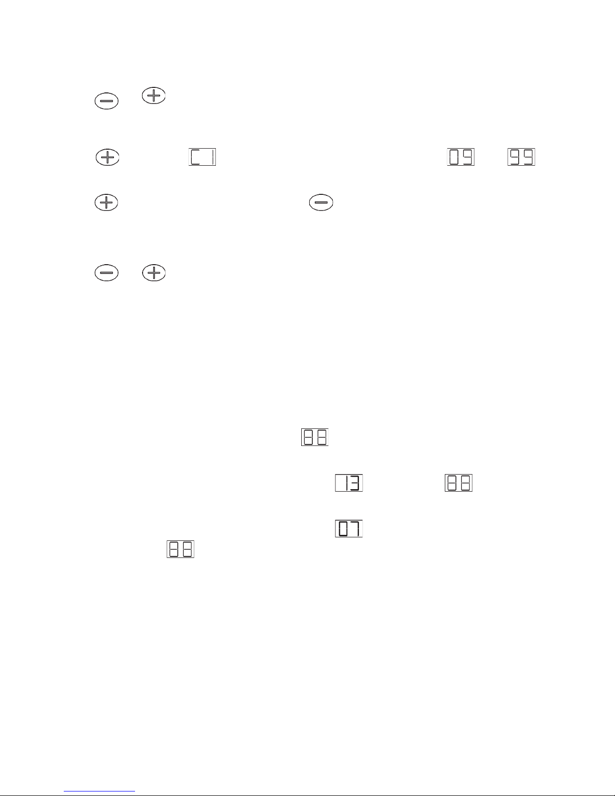
2.23 - Counters
The regulation is equiped with 6 counters to count heating cycles (the unit is 100 cycles).
Press
and during 3 sec.
The setting menu starts (see § 6.3).
Press during 3 sec. : °C will be on display for counter #1, alternating with °C and bar,
meaning power breaker #1 K1 is totalling more than 0999 x 100 = 99.900 cycles.
Press
to shift to counter #2. Conversely press to return to previous counter.
Starting this menu will automatically restore the weekly shift of the 6 power stages starting sequence back
to the 1 to 6 order, but will not zero the counters.
Press
and during 3 sec. to exit the counters menu.
Page 37
Ascari MA12 -p. 37 -
Once a year we recommend to have the boiler checked by a qualified technician.
- Pressure inside the heating circuit needs to be controlled a a regular basis (pressure when cold will have to
remain over 1 bar).
- Frist a few days after cut-over, later at least once a year, check electric connections tightness of the heating
elements and power supply.
- Floor heating: In case of overheat the temperature limitator (60°C) will cut power supply to heating
elements .
- Radiators: The limitator (100°C) also cuts power to heating elements.
- After solving the failure, reset the boiler pressing the small red button in the middle of the sensor's head.
(see §1.3.1).
- Numerous power losses or lack of power: it might happened one (or several) connection(s) from power to
heating elements is(are) defective (powerloss) or cut (power failure). In this case change defective
element(s).
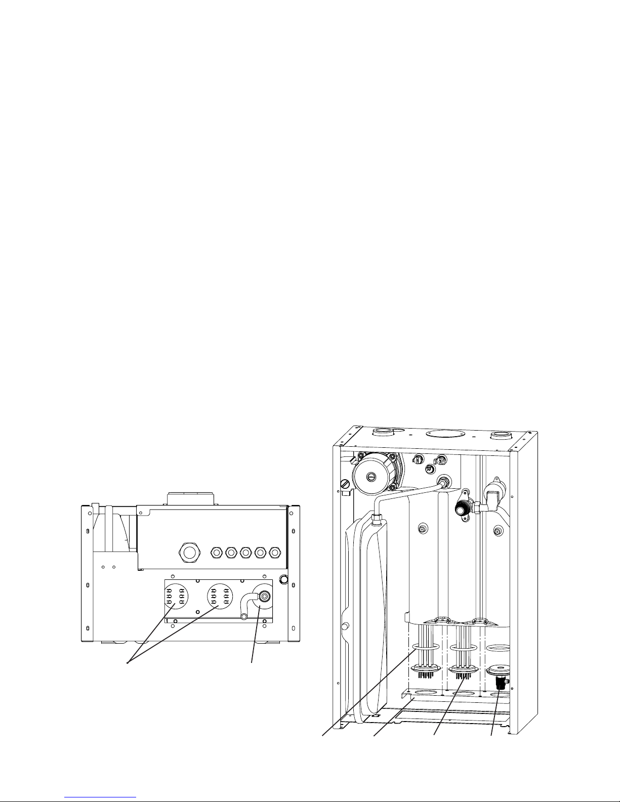
Cut the power supply, drain by using drain tap, disconnect elements, remove elements fastener and
remove/replace damaged element(s). (seer § 1.2 to access heating elements).
View from below
(Access trap-door to elements removed)
Heating elements
Front view
(electric box removed)
O-ring Heating
elements
Element
fastener
Drain tap with hose
Cap with
drain tap
2.25 - Maintenance
2.26 - Overheating and replacement of heating elements
Page 38
Ascari MA12 -p. 38 -
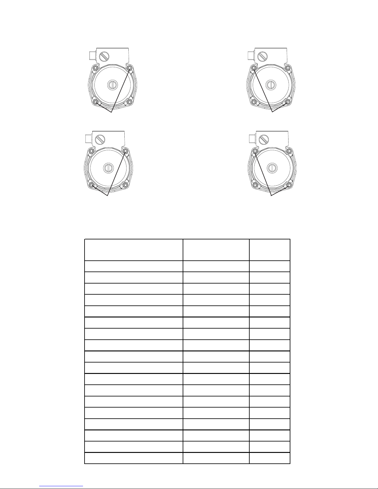
Fastening the pump
If the pump is producing some abnormal noise, slightly unscrew without creating leackage, then screw
again following instructions below.
1 - screw two opposite screws with a stroke of 3
Nm.
2 - screw the other two opposite screws with a
stroke of 3 Nm
3 - screw the first two opposite screws with a
stroke of 5 Nm.
4 - screw the last two opposite screws with a
stroke of 5 Nm.
12 MA
230 V mono
Side casing
B4484737 1
Front casing
B4484730 1
Control panel
B1758741 1
Pump
B1243544 1
Klixon 60°
B1243400 1
Klixon 100°
B1243418 1
3bar relief valve
B1239103 1
8L expansion vessel
B1472534 1
Water sensor
B1243546 1
Outside sensor (option)
B1243586 1
6kW heating element
B1243558 2
Heating element gasket
B1657044 3
20A tetrapole switch
B1243561 4
Fuse holder
B1243146 1
4A fuse size 5 x 20
B1243147 1
Display
B1943599 1
C1 electronic card
B1943600 1
Temperature display
B1243534 1
SPARE PARTS LIST
Designation Reference
0105276
Page 39

Ascari MA12 -p. 39 -
NOTE
Page 40

Ascari MA12 -p. 40 -
 Loading...