

Page 1

illon
recision
Products, Inc.
Manufacturers of
The World's Finest
Loading Equipment
Dillon RL 550B Casefeeder
Installation Instructions
May 2007
550 Casefeed Manual, May 2007 5/22/07 8:29 AM Page 1
Page 2

Exploded View, Dillon RL 550B Casefeeder
550 Casefeed Manual, May 2007 5/22/07 8:29 AM Page 2
Page 3

Congratulations on your purchase of
Dillon’s RL 550 B Casefeeder. Please take a
moment to read through these instructions
carefully before installing the casefeeder on
your machine.
1. Check the contents of the box and verify
that all parts have been supplied. Refer to
the exploded view on the opposite page.
Hardware Kit: Part #14457
Additional Tools Needed:
• Two 7/16” wrenches
2. Begin by removing the operating rod
from the primer system [
FIGURE 1].
3. Next, remove the cartridge chute
[
FIGURE 2] (applicable for machines with
strong mount only), shellplate, index ball,
spring and toolhead [
FIGURE 3] from your
machine.
3
Hardware Kit Contents
Description
Qty.
1/4 - 20 x 1 3/4 Hex Cap Screw
2
1/4 washer
2
1/4 -20 Flanged Nut
2
8-32 x 1/2 Coun tersunk Flathead
2
1/4 -20 x 5/8 Button Head Cap Screw
1
13/16 Washer
1
3/16 Allen Wrench
1
5/32 Allen Wrench
1
1/8 Allen Wrench
1
3/32 Allen Wrench
1
FIGURE 1
FIGURE 2
550 Casefeed Manual, May 2007 5/22/07 8:29 AM Page 3
Page 4

4. Next, remo
ve the platform assembly
[
FIGURE 4] from the machine. This is
accomplished by removing the two cap
screws located toward the center of the
platform, with the supplied 3/16” Allen
wrench. Once you have the platform off the
machine, disassemble the roller bracket
from the platform[
FIGURE 4] by removing
the two flat head screws, with the supplied
3/32” Allen wrench.
5. Attach the new 550 CF Lower Feeder
Assembly (part #96002) to the platform
[
FIGURE 5] with the new 8-32 x 1/2” flat
head socket screws and Allen wrench
provided in the hardware package – be sure
to tighten.
6. Re-attach the platform and Casefeeder
housing to the shaft (make sure not to forget
the failsafe return br
acket), only lightly
tighten screws at this point. You will need
to use an empty toolhead with a po
wder
die in the station 1 position and the
supplied alignment tool as sho
wn in
FIGURE 3
FIGURE 4
FIGURE 5
550 Casefeed Manual, May 2007 5/22/07 8:29 AM Page 4
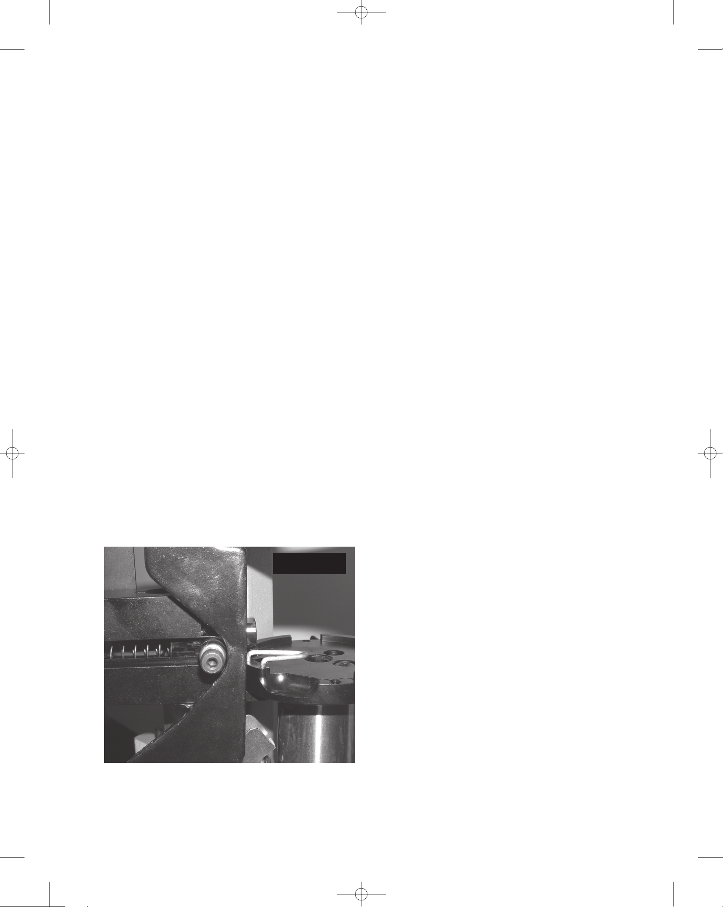
Page 5

[FIGURE 6]. Position the toolhead in the
frame (be certain to install toolhead pins)
and raise the platform up until the small
diameter end of the alignment tool goes
freely into the primer punch hole [
FIGURE
7] y
ou will need to pull the spring-loaded
plunger back out of the way. Radial
adjustment may be necessary to get the tool
to go in and out freely. Once this has been
accomplished, +firmly tighten down the
two bolts [
FI
GURE
8]. Cycle the operating
handle, watching the alignment tool move
in and out of the primer punch hole. Make
sure the tool goes freely after tightening the
screws. You will need to make sure that the
lower casefeed assembly that you just
installed does not make contact with the
primer feed body on the priming stroke
[
FIGURE 9]. If it does, you will need to
loosen and rotate the platform
counterclockwise and retighten. Remove
the toolhead and alignment tool once y
ou
are finished.
FIGURE 6
FIGURE 7
FIGURE 8
FIGURE 9
5
550 Casefeed Manual, May 2007 5/22/07 8:29 AM Page 5
Page 6

7. Remove the two rear mounting bolts and
the front right mounting bolt holding the
machine down to the strong mount or
bench.
8. Attach the CF Post Support (part #18907)
as shown in [FIGURE 10] with the left rear
mounting screw only
, finger tight only, do
not fully tighten.
9. Align the rear hole in the 550 Casefeed
Cam (part #18911) with the right rear
mounting hole in the mac
hine frame
[
FIGURE 11] and reinstall the 1/4 -20 bolt
with washer and finger tighten the nut. Pull
the plunger back and rotate the cam into
position so the front mounting hole on the
cam aligns with the front mounting hole in
frame and reinstall the 1/4 -20 bolt and
finger tighten the nut [
FIGURE 11]. We
recommend that the adjustment be
completed without a shellplate on the
platform so that the bearing on the plunger
will be allowed to bottom out on the
housing. Adjustment of the cam is as
follows: start with the cam pushed all the
way back toward the post support and pull
the operating handle down until the roller
just reaches the center of the flat on the
cam[
FIGURE 12] (Hint: You can use a
po
wder die to support the platform in
position needed for cam adjustment – see
[FIGURE 13]). Slide the cam forward until it
just barely touches the roller and tighten
the two mounting bolts on the cam (be
sure not to release the handle until they are
tightened). Make sure that the roller on the
plunger is centered on the cam and tighten
the mounting bolts. Cycle the oper
ating
handle a few times and make sure the
plunger operates freely.
FIGURE 10
FIGURE 11
FIGURE 12
6
550 Casefeed Manual, May 2007 5/22/07 8:29 AM Page 6
Page 7

10. Tighten the remaining mounting bolts
for the post mount to the frame.
11. Re-attach the Primer System Operating
Rod [
FIGURE 14] and the new Cartridge
Chute [
FIGURE 15].
12. Insert the P
ost (part #17124) into the
550 CF Post Support (part #18907) (curve
of the post needs to go to the right [
FIGURE
16]) and fasten with the tw
o 1/4 -20 bolts,
FIGURE 13
FIGURE 14
FIGURE 15
FIGURE 16
7
550 Casefeed Manual, May 2007 5/22/07 8:29 AM Page 7
Page 8

washers and nuts that are supplied in the
hardware package. The post will have some
movement to it once the bolts have been
tightened down. Set the 550 CF Upper Bowl
Assembly (part #96001) onto the post and
using the 1/4 - 20 x 1/2” screw (supplied in
the hardware bag) finger tighten the screw
against the post. Insert the 550 CF Upper
Casefeed Tube (part #18910) into the clip on
the casefeed bowl, double check that the
flare on the tube is the end that is inserted
[
FIGURE 17]. Install the casefeed adaptor
(from the conversion kit that you separately
purchased) into the mounting hole on the
550 CF Lower F
eeder Assembly, make sure to
align the notch on the adaptor with the
corresponding cutout in the housing. Insert
the Lo
wer Casefeed T
ube (part #18908) into
the adaptor and clip the tube into the
mounting clip attached to the Lower Feeder
Assembly [
FIGURE 18].
Slide the large end of the micro switch
housing over the Upper Casefeed Tube and
then slide it down until the Lower Case
Feed Tube will insert into the Micro Switch
Housing, once installed it should appear as
sho
wn in the upper left hand view. Make
sure that all of the tubes are in alignment
then tighten the screw locking the Upper
Casefeed Bowl Assembly to the post.
FIGURE 17
FIGURE 18
FIGURE 19
8
550 Casefeed Manual, May 2007 5/22/07 8:29 AM Page 8
Page 9

13. Once you have the casefeeder setup
and before you set the machine up to load
a caliber, insert the Station 1 Locator from
your conversion kit into the casefeed
housing as shown in[
FIGURE 19].
Once the Station 1 Locator is installed,
setup the machine with the shellplate and
die set for the desired caliber you are going
to load, don’t forget to install the casefeed
plate. In the hardware bag is included a
large 13/16” washer, this is the spacer for
the casefeed plate (please reference
attached chart for plate size). If you
reference the list supplied it will indicate
which calibers require the spacer (see
attached view for installation). The clutch
on the casefeed plate is factory pre-set at 5
in/lbs of torque, this will allow the plate to
slip if it should become jammed. Over
tightening the clutch will not let it operate
correctly and can cause motor failure. We
recommend that you fill the casefeeder
with two scoops of shells with the 550
cartridge bin so as not to over fill the
casefeed bowl. When you are ready to load
if you pull the operating handle to the
down position (before you turn on the
casefeeder) it will make certain that the first
case that drops does not have the
possibility of falling over. After there are at
least 5-6 cases in the tube you can release
the operating handle. If you begin to
experience a problem with the case not
feeding into the shellplate, die or the case
is bouncing out of the shellplate then you
will need to refer to the troubleshooting
section for fine adjustment procedures for
the cam.
9
Exploded View, Casefeed Plate Assembly
550 Casefeed Manual, May 2007 5/22/07 8:30 AM Page 9
Page 10

Exploded View, CF Lower Feeder Assembly
550 Casefeed Manual, May 2007 5/22/07 8:30 AM Page 10
Page 11
11
• Fine Adjustment of Cam: If you are
experiencing a problem with the case not
feeding all of the way into the shellplate
(and/or sizing die) or bouncing back out of
the shellplate, you will need to fine adjust
the cam for each and every caliber that you
are loading. You will want to start with a
case from the caliber you are preparing to
load in the first station of the shellplate. In
the following procedure you will practically
repeat the steps for setting up the cam on
initial installation with the exception of
letting the plunger rest on the case in the
shellplate instead of the housing. Pull the
operating handle down until roller on
casefeed plunger reaches about the center of
the flat on the cam and the plunger is resting
on the case in the shellplate. Loosen the
cam and slide it in or out until it is just
barely touching the roller, then re-tighten the
mounting bolts on the cam, be sure not to
release the handle until tightened. Once y
ou
have finished loading the caliber that you
have fine-tuned the cam for, you will want to
return it to its original position b
y repeating
the setup steps in Note 9 [
FIGURE 20].
• If you are having trouble with the case
sliding through or sticking in the Station 1
locator make sure there are no burrs on the
inside edges of the tracks or that they have
not been bent or crushed.
• If you are experiencing a sticky action
with the plunger you may have tumbling
media or other debris that is causing the
plunger to stick or bind. You will have to
remove the shellplate, shellplate bolt,
indexing star and the Station 1 locator so
you can remove the plunger from the
casefeed body. To remove the plunger it
will be easier to pull the operating handle
down so the roller is on flat in the center of
the cam to reduce spring tension. Slowly
remove the shoulder bolt and two
bearings. The spring will want to push the
plunger out of the body, once the bolt is
out remove the plunger and spring from
the body. Use a clean rag to wipe off the
plunger and the inside of the housing. Relube the plunger and housing with MILCOMM TW-25B (part #15732) grease or
equi
valent. You can also re-lube the
bearing assembly at this time. Re-insert
spring into plunger and slide assembly into
housing making sure spring is held do
wn
by the pin at end of housing. Install
bearing assembly and tighten. At this time
also lube the channel that the bearing rides
in on the housing with the same grease.
• If you have double feed, it will be easiest
to clear out the lo
wer feed tube and
remove the casefeed adaptor so you can
pull the plunger all the way back and
remo
ve the cases.
• If you are having trouble with the case
lining up or jamming in the sizing die
mouth, make sure you are using a sizing
die with a r
adiused entry on the mouth. We
recommend that a Dillon Sizing Die be
used – Dillon dies have radiused mouths
that allow the case to enter the die easier.
• If you need further assistance please call:
1-800-223-4570
Troubleshooting and Helpful Hints
FIGURE 20
550 Casefeed Manual, May 2007 5/22/07 8:30 AM Page 11
Page 12

Dillon RL 550B Casefeeder Calibers
Caliber Conversions
CONV. PART # CALIBER STATION 1 LOCATOR CASEFEED ADAPTOR
1
4206 .25-20 WIN W ( 14225 ) BLUE (13075)
1
4284 .30 LUGER 5 ( 14224 ) GREEN (13450)
14204 .30 MAUSER 5 ( 14224 ) RED (13143)
1
4205 .32 S&W LONG D ( 14223 ) GREEN (13450)
14283 .32 H&R MAG D ( 14223 ) BLUE (13075)
14206 .32-20 WIN W ( 14225 ) BLUE (13075)
1
4284 9 MM / 9x21 / .38 SUPER 5 ( 14224 ) GREEN (13450)
14285 9x25 DILLON W ( 14225 ) RED (13143)
14287 .38 SUPER COMP. 3 (14227) GREEN (13450)
14208 .38 S&W 2 (14226) PURPLE (18076)
14286 .38 SPL. 2 ( 14226 ) ORANGE (13386)
14289 .357 SIG W ( 14225 ) PURPLE (18076)
14286 .357 MAG 2 ( 14226 ) ORANGE (13386)
14288 .38-40 WIN N ( 14228 ) YELLOW (13442)
14292 .40 SUPER 1 ( 14231 ) RED (13143)
14292 .400 COR-BON 1 ( 14231 ) RED (13143)
14289 .40 S&W W ( 14225 ) PURPLE (18076)
14285 10 MM W ( 14225 ) RED (13143)
14290 .41 MAG. 6 ( 14229 ) YELLOW (13442)
14288 .44-40 WIN N ( 14228 ) YELLOW (13442)
14291 .44 COLT 4 ( 14230 ) YELLOW (13442)
14209 .44 RUSSIAN 4 ( 14230 ) RED (13143)
14291 .44 SPL. / 44 MAG. 4 ( 14230 ) YELLOW (13442)
11441 .45 GAP 1 ( 14231 ) GRAY (12670)
14292 .45 ACP 1 ( 14231 ) RED (13143)
19140 .45 AUTO RIM UNIVERSAL (19139) RED (13143)
14279 .45 S&W SCHOFIELD C ( 14232 ) YELLOW (13442)
14279 .45 COLT C ( 14232 ) YELLOW (13442)
14210 .45 WIN MAG. 1 ( 14231 ) YELLOW (13442)
14279 .454 CASULL C ( 14232 ) YELLOW (13442)
** CONVERSION PART NUMBERS ONLY CONTAIN THE STATION 1 LOCATOR AND THE CASEFEED ADAPTOR **
550 CASEFEED WILL NOT WORK ON RIFLE CALIBERS, INCLUDING 30 CARBINE & 22 HORNET
550 CASEFEED STATION 1 LOCATORS ARE NOT THE SAME AS 650 STATION 1 LOCATORS
550 Casefeed Manual, May 2007 5/22/07 8:30 AM Page 12
Page 13

13
SHELLPLATE LOCATOR PIN POWDER FUNNEL CASEFEED PLATE SPACER
O
(12013) 3 (14060) R (13243) SP (21073)
5
(13743) 3 (14060) C (13564) SP (21073)
5 (13743) 3 (14060) C (13564) SP (21073)
D
(13092) 3 (14060) SW (13171) SP (21073)
D (13092) 3 (14060) SW (13171) SP (21073)
O (12013) 3 (14060) S (12845) SP (21073)
5
(13743) 3 (14060) F (13806) SP (21073)
5 (13743) 2 (14062) F (13806) LP (21072)
3 (13334) 3 (14060) F (13806) SP (21073)
U (12944) 2 (14062) F (13806) LP (21072)
2 (13751) 2 (14062) D (13599) LP (21072) X
5 (13743) 2 (14062) F (13806) LP (21072)
2 (13751) 2 (14062) D (13599) LP (21072) X
N (10004) 4 (14047) W (13600) LP (21072) X
1 (13692) 1 (13930) W (13600) LP (21072)
1 (13692) 1 (13930) W (13600) LP (21072)
5 (13743) 2 (14062) W (13600) LP (21072)
5 (13743) 2 (14062) W (13600) LP (21072)
6 (13120) 1 (13930) H (13240) LP (21072) X
N (10004) 4 (14047) 4 (13474) LP (21072) X
4 (13610) 1 (13930) G (13427) LP (21072)
4 (13610) 1 (13930) G (13427) LP (21072)
4 (13610) 4 (14047) G (13427) LP (21072) X
1 (13692) 1 (13930) E (13782) LP (21072)
1 (13692) 1 (13930) E (13782) LP (21072)
H (13010) 4 (14047) E (13782) LP (21072)
C (13334) 4 (14047) E (13782) LP (21072)
C (13334) 4 (14047) E (13782) LP (21072) X
L (12703) 1 (13930) E (13782) LP (21072)
C (13334) 4 (14047) E (13782) LP (21072) X
Additional Caliber Components
550 Casefeed Manual, May 2007 5/22/07 8:30 AM Page 13
Page 14
I
ncrease the stability of
your reloading bench
with Dillon’s new Strong
Mounts. These heavy
gauge steel Strong Mounts
increase the machine’s
“footprint” to over 10”,
spreading the load over the whole bench
instead of stressing the leading edge.
Strong Mounts raise your machine 6” to 8”,
providing a comfortable work height for people who prefer to stand while reloading. For
some XL 650 owners, overhead clearance can
become a problem, so we designed a mount
especially for this application. The XL 650-only
mount raises the machine 6” above the bench
top. All mounts come with all the fasteners
necessary to mount your machine (550/650
mount includes RL 550B bin bracket) and are
coated with a durable black wrinkle finish.
RL550/XL650 Strong Mount
Stock #22051
D
illon’s original RL
1000 came
equipped with a simple,
shallow aluminum bullet tray that was
designed for economy
of motion when loading.
For years, our attempts
to duplicate the efficiency and the “feel” of
that tray in other machine applications were
less than satisfactory. It took the development
of the Strong Mount for the RL 550 and the XL
650 to enable us to place the redesigned tray
exactly where it needed to be.
Our aluminum tray works on the Square
Deal ‘B’, the RL 550B and XL 650 when
equipped with the RL 550/XL 650 Strong
Mount, and a separate kit is available for
the RL 1050. Comes with a Dillon Blue
powder coat finish.
Bullet Tray Kit
Stock #22214
Strong Mount
Bullet Tray Kit
M
agnum rifle cartridges can require
from 70 grains to well in excess of 100
grains for a single charge. Our new “Belted
Magnum” Powder System features a new,
maximum-capacity, steel powder bar that
can dispense more than 100 grains of
extruded IMR powder.
Our magnum powder system can be
used with your RL 550B, XL 650 or AT
500 reloader, and is ideal for loading
large-caliber, magnum rifle cartridges.
We tested this system with various
extruded rifle powders and found that
powder charge variations stayed within
plus-or-minus three-tenths of a grain.
The “Belted Magnum” Powder System is
based on our SL 900 Shot Dispenser, so the
Maximum Charge Bar won’t work in our
standard powder measures – you’ll need to
buy the entire system. The good news is that
the “Belted Magnum” Powder System has an
integral drain, so it’s easy to empty the
hopper in order to change powder types; so,
if you load several big calibers with
various powders, it’s easy to switch from
one to another.
Keep plenty of extra powder on hand,
because when you’re dispensing 100-
plus grains into every cartridge, you’re
gonna need it!
Magnum Powder System
Stock #97126
‘Belted Magnum’ Powder System
Toolhead and
Toolhead Stand
Not Included
Toolhead Cover (L) for use
without powder measure.
Stock #11142
Quick-Change Cover (R) for
use
with pow-
der measure.
Stock #11143
Dust Covers
1
” die lock rings
and a 1” wrench
to fit them gives you
much more room to re-adjust your dies after
they’re already mounted in the toolhead.
5-Pack of Die Lock Rings
Stock #10669
1” Dillon Bench Wrench Stock #10842
Bench
Wrench
550 Casefeed Manual, May 2007 5/22/07 8:30 AM Page 14
Page 15

15
Notes
550 Casefeed Manual, May 2007 5/22/07 8:30 AM Page 15
Page 16

16
Dillon Precision Products, Inc.
8009 E. Dillon’s Way
Scottsdale, AZ 85260
(480) 948-8009
FAX (480) 998-2786
Web Site: www.dillonprecision.com
Technical Support E-mail: dillon@dillonprecision.com
See our Troubleshooting Section online at www.dillonprecision.com
Technical Support & Customer Service
(800) 223-4570
On the cover…
The RL 550B is pictured with optional accessories:
Strong Mount #22051
Low Powder Sensor #16306
Bullet Tray #22214
Other accessories available for the RL 550B include:
Video Instruction Manual #14621
Machine Cover #13795
Maintenance Kit & Spare Parts Kit #97016
The
Blue Press, Dillon’s monthly catalog, has a complete listing
of accessories available for all machines.
550 Casefeed Manual, May 2007 5/22/07 8:30 AM Page 16
Page 17

17
550 Casefeed Manual, May 2007 5/22/07 8:30 AM Page 17
 Loading...