

Page 1

IIPP NNeettwwoorrkk CCaam
Pan/Tilt Remote Control &
With Audio & Night Vision
meerraa
User’s Guide
Page 2

`
DN-16032 User’s Guide
--------------------------------------------TABLE OF CONTENTS--------------------------------------------
1. OVERVIEW .............................................................................................................................. 3
1.1 PRODUCT DESCRIPTION ............................................................................................................. 3
1.2 PRODUCT FEATURE .................................................................................................................... 3
1.3 PRODUCT SPECIFICATION ........................................................................................................... 3
1.4 PRODUCT ACCESSORIES INCLUDE ............................................................................................... 4
1.5 SYSTEM REQUIREMENT .............................................................................................................. 5
1.6 DN-16032 EXTERIOR FUNCTION INTRODUCE ............................................................................... 5
1.7 TV_OUT FUNCTION INTRODUCE ................................................................................................. 6
1.8 PRODUCT SET-UP..................................................................................................................... 7
2. UTILITIES AND TOOLS .............................................................................................................. 8
2.1 CAM_EZ SEARCH ..................................................................................................................... 8
2.2 USE IP-CAM AND TEST THE IMAGE FUNCTION FOR THE FIRST TIME ................................................ 8
2.3 HOW TO SET UP IP CAM ...................................................................................................... 10
2.4 SETTING THE WAY TO OBTAIN THE IP ADDRESS OF IP-CA M ......................................................... 10
2.5 IP-CAM NETWORK FRAMEWORK INSTALLATION ......................................................................... 17
2.6 INSTALLATION FOR IP SHARE .................................................................................................... 24
2.7 INTERNET IP SHARING & AUDIO SETTING ................................................................................... 27
PPaann//TTiilltt IIPP SSuurrvveeiillllaannccee CCaammeerra
a
3. GETTING STARTED ................................................................................................................ 28
3.1 SYSTEM LOGIN ......................................................................................................................... 28
3.2 LIVEVIEW ................................................................................................................................. 29
3.3 TAKE A SHOT ............................................................................................................................ 32
4. ADVANCED FUNCTION WITH LIVEVIEW ................................................................................... 33
4.1 IMAGE ADJUSTMENT ................................................................................................................. 33
4.2 AVI RECORD SETUP ................................................................................................................. 34
4.3 ZOOM IN DISPLAY ..................................................................................................................... 35
4.4 MOTION DETECTION SETUP ...................................................................................................... 35
4.5 MOTOR CONTROL .................................................................................................................... 36
5. ADVANCED APPLICATION ...................................................................................................... 36
5.1 IMAGE SETUP ........................................................................................................................... 37
5.2 CAPTURE VIEW ........................................................................................................................ 37
5.3 EVENT TRIGGER ....................................................................................................................... 38
5.4 NETWORK SETUP ..................................................................................................................... 39
5.5 SERVER SETUP ........................................................................................................................ 41
5.6 ADMINISTRATION SETUP ........................................................................................................... 44
5.7 SOFTWARE UPDATE .............................................................................................................. 45
APPENDIX ................................................................................................................................ 48
DN-16032 USER’S GUIDE PAGE 2/61 Rev. PV1.0
Page 3

`
DN-16032 User’s Guide
APPENDIX A. USING A PPPOE DIALUP CONNECTION AND DDNS WITH THE DN-16032 EZ IPCAM (USING
A
HUB ) 48
APPENDIX B. FAQ: ......................................................................................................................... 57
1. OVERVIEW
1.1 PRODUCT DESCRIPTION
DN-16032 is an easy and effective IP Camera product for remote monitoring
/administrating. The setup for this device is simply. Built-in Web server allows you to use
web browser (e.g., Microsoft ID) through LAN or broadband network in any time and any
place. Type the IP address of the IP-CAM camera on the network address line to carry
out the works of remote image monitoring and administration. Meanwhile, the user can
remote control the motor of the camera to change the direction of monitoring and handle
the real-time image of the monitored location.
In addition, the camera supports many network protocols such as PPPoE, DHCP,
STATIC IP, DDNS, SMTP, FTP and NTP with high-performance SDRAM control and
memory card access. The built-in TV Out decoding/coding device can display the most
popular TV screen (supporting NTSC and PAL) in families with combining fast Motion
Detection and SD Expansion Card in hardware. Moreover, DN-16032 is equipped with IR
LED lightening, so it has the function of night vision. Besides, this device also has the
function of recording and real-time photographing. To a family, such remote monitoring
can reach professional security and have great fun.
1.2 PRODUCT FEATURE
Use standard Web Browser ID to monitor, record, and shot remotely
Maximum 640x480 Full screen
Allow to view images from multi-camera
Allow on-line image viewing remotely for multi-user simultaneously
Motion Detect, monitor and store triggered photographs at any time for the whole day
Remote real-time recoding to the device and trigger to sending images to FTP & E-Mail &
SD Card & PC
Support virtual IP and port switch in IP DSALM
Support several communication protocols, TCP/IP, DHCP, SMTP, FTP, PPPoE, DDNS,
Use functional authority setting, name registration and password protection
Support the dynamic IP network function of DHCP
Support ADSL network of PPPoE user
Standard RJ-45 network connector, support 10/100 Base-T network transmission
1.3 PRODUCT SPECIFICATION
Image Size: 160x120、320x240、640x480 adjustable
Image Quality: Fine、Normal、Basic adjustable
Video Frequency: 50 Hz for PAL、60 Hz for NTSC
PPaann//TTiilltt IIPP SSuurrvveeiillllaannccee CCaammeerra
a
DN-16032 USER’S GUIDE PAGE 3/61 Rev. PV1.0
Page 4
`
DN-16032 User’s Guide
Image Compression Format : M-JPEG
Focal Distance Range : From 30mm to infinity adjustable
Digital Zoom : 4X
Video Recording : Video Frame rate setting : auto; 1, 3, 5, 10, fps
Motion Detect Trigger Function, image sent to FTP & E-Mail & SD Card & PC
Support TCP/IP、SMTP、FTP、PPPoE、DHCP Protocol
Network DHCP or manual setting network IP, and support ADSL network of PPPoE
user
Build-in web server and the functions of Active-X and Java
Remote single picture captured with JPG file format, remote continuous screen
recorded with AVI format
Microphone : High touch 10φ-40db±3
TV OUT Video Output: support 50 Hz for PAL、60 Hz for NTSC
Night vision
lightening illumination: Auto and Manual selection, IR LED x 6/ 5φ/850λ
Monitoring angle: Vertical angle: Up/Down Tilt +180 to –35 degrees
Horizontal angle: Left / Right Pan +/- 175 degrees
Standard RJ-45 network connector, support 10/100 Base-T network transmission
5V/ 1.5A exterior switching power adaptor
Power Consumption : 650mA(max)2.5W(max)
PPaann//TTiilltt IIPP SSuurrvveeiillllaannccee CCaammeerra
a
Operating environment : 5˚C~40˚C
Storage temperatures : -0˚C~55˚C
Humidity : 5%~85% non-condensing
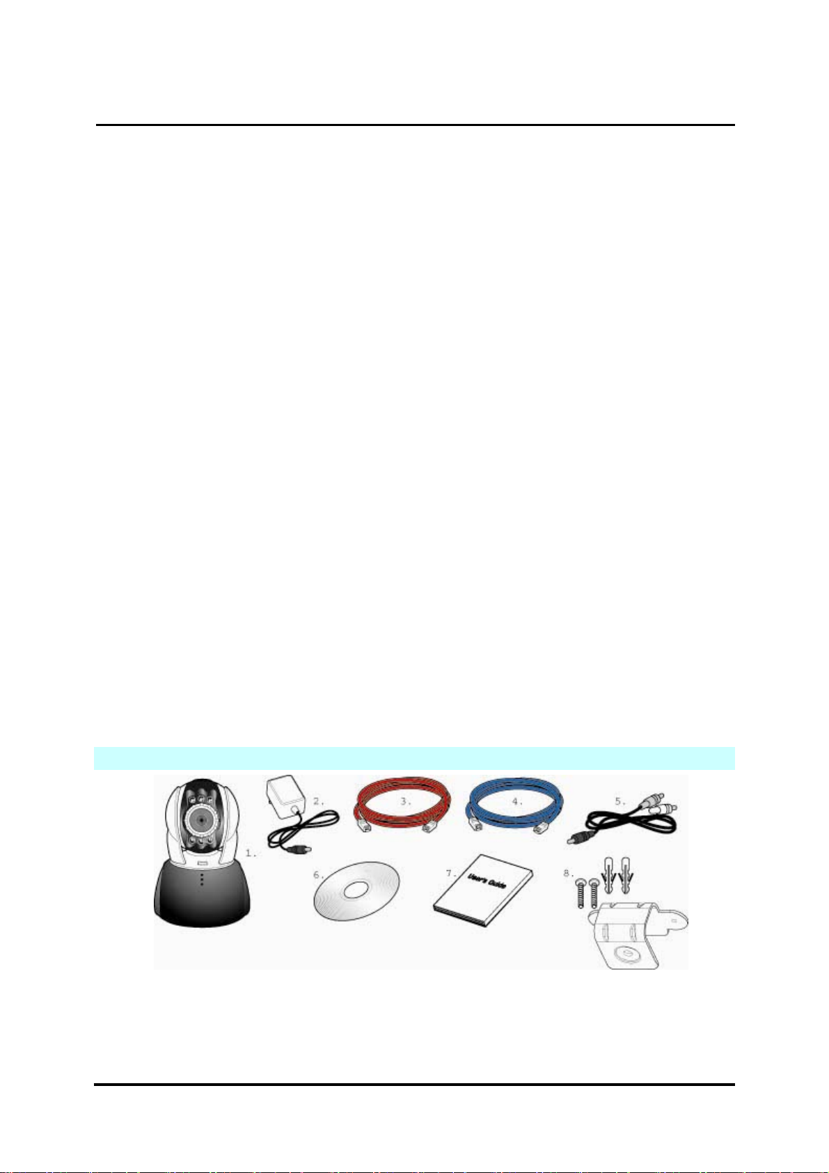
1.4 PRODUCT ACCESSORIES INCLUDE
1. Rimax DN-16032
2. Power adaptor, 5V/ 1.5A Switching Power adaptor
3. Ethernet Cable (red), used to connect to the network card of PC for testing and
configuring the product
DN-16032 USER’S GUIDE PAGE 4/61 Rev. PV1.0
Page 5
`
DN-16032 User’s Guide
4. Ethernet Cable (blue), used to connect to Hub, ADSL modem, IP Share
5. TV OUT A/V Cable
6. Setup CD
7. This User’s Guide
8. Accessory for hanging and fastening
1.5 SYSTEM REQUIREMENT
PC
Processor: Intel Pentium 4 ® 1.4GHz or above is recommended
RAM: 256MB or above
Operation System: Windows 2000
®
or Windows XP®
Hard Disk: Minimum 10MB or above
Network
Network Card: 10/100 base-T
Network Setup: Accessing Internet normally
Web Browser: Microsoft Internet Explorer 6.0 or above
Connect Network Equipment: ADSL modem, IP Share or Hub
Active-X for activating control items and plug-in
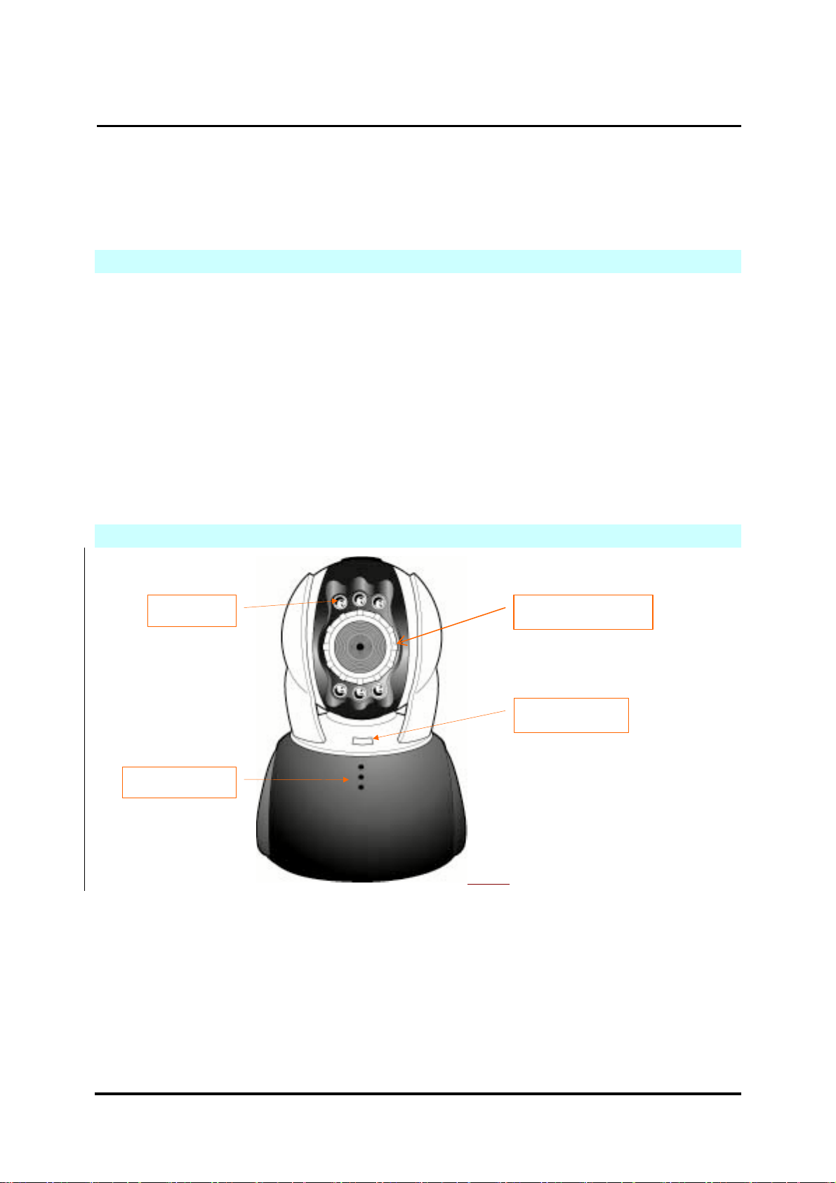
1.6 DN-16032 EXTERIOR FUNCTION INTRODUCE
PPaann//TTiilltt IIPP SSuurrvveeiillllaannccee CCaammeerra
a
IR LEDX6
Microphone
Focus Adjustable
Status Light
DN-16032 USER’S GUIDE PAGE 5/61 Rev. PV1.0
Page 6
`
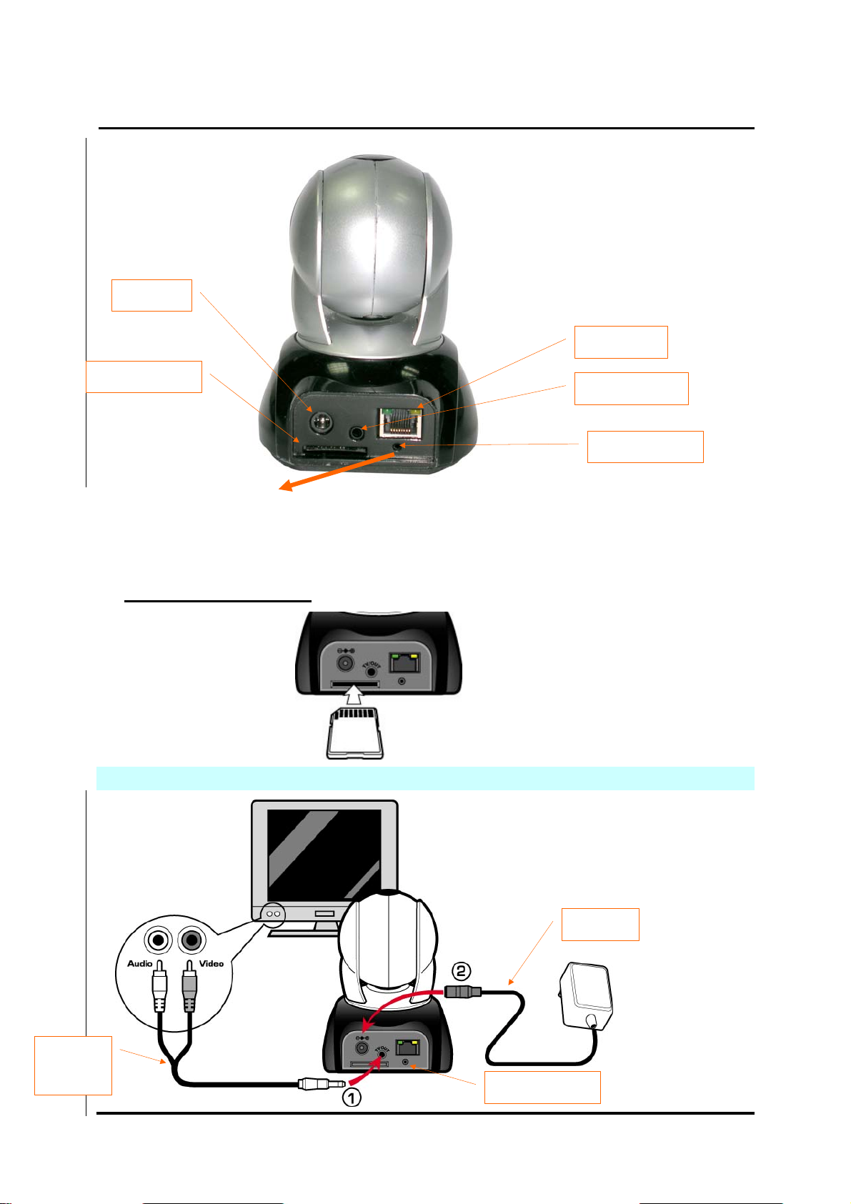
DC JACK
DN-16032 User’s Guide
PPaann//TTiilltt IIPP SSuurrvveeiillllaannccee CCaammeerra
RJ-45 JACK
a
SD Card Slot
TV_OUT JACK
Reset Switch
Usage of Reset Switch:
While the system is active normally, press and hold Reset Switch for a short time (about 3 to 5
seconds) till Status LED lights up. The system will restart the device and recover to the factory
default settings.
SD Card Usage Diagram:
1.7 TV_OUT FUNCTION INTRODUCE
TV_OUT
Cable
Adapter
Reset Switch
DN-16032 USER’S GUIDE PAGE 6/61 Rev. PV1.0
Page 7
`
DN-16032 User’s Guide
1. First, insert the TV_OUT cable to the place as shown in Figure 1.
2. Next, plug in power adapter as shown in Figure 2. Press and hold Reset switch for
three seconds. Then, release it. The IP-CAM will access into TV_OUT mode.
3.TV_OUT operation description:
a. Hold to change mode: For the default setting for TV_OUT is NTSC system, if you
want to use PAL system, please press and hold Reset switch about
three seconds to switch between NTSC and PAL systems.
b. Push to exit : Press Reset to access into TV screen and adjustable
50Hz,60Hz,Outdoor
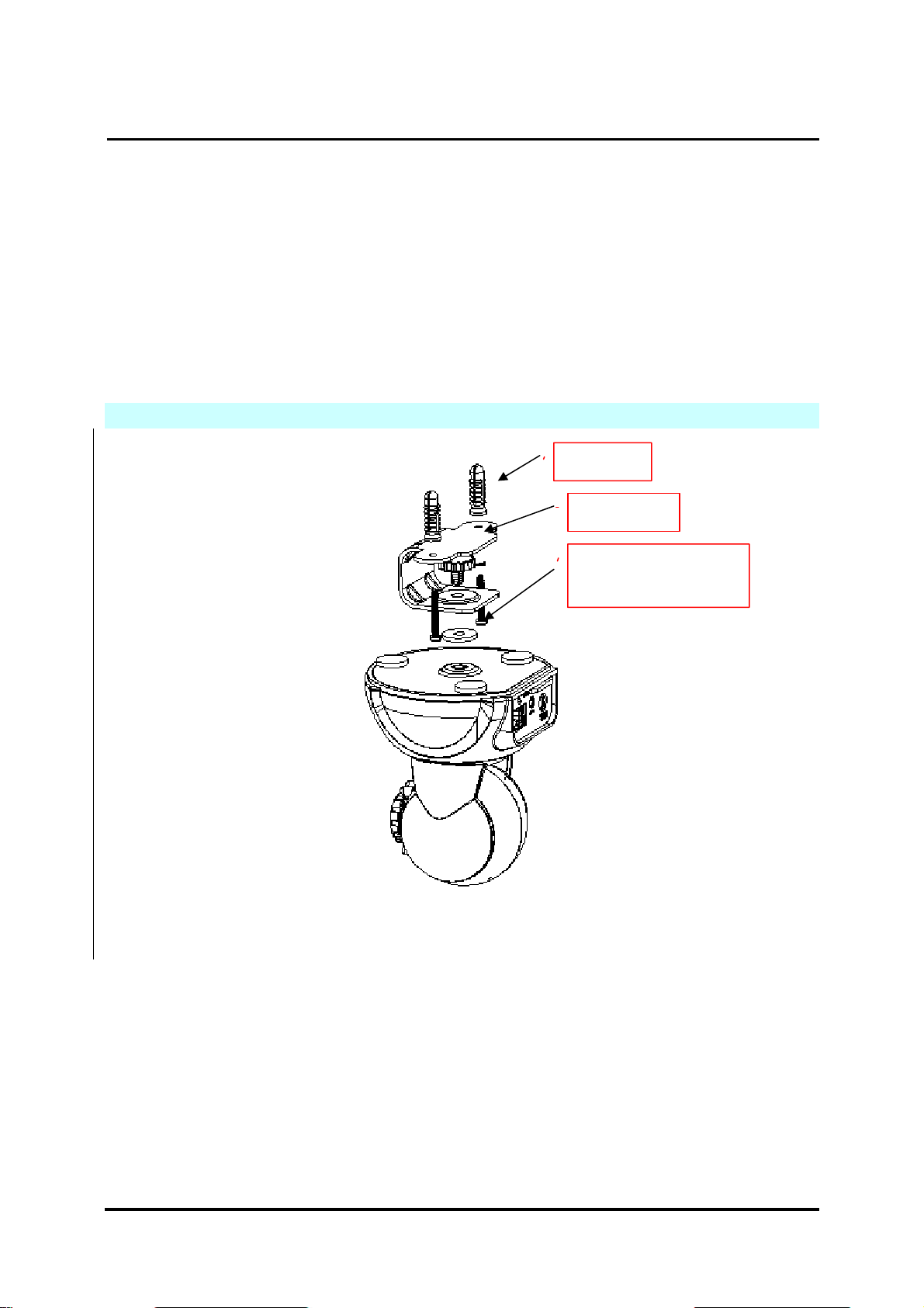
1.8 PRODUCT SET-UP
PPaann//TTiilltt IIPP SSuurrvveeiillllaannccee CCaammeerra
Anchor
Frame
a
Screw (P head
M3.5X25)
DN-16032 USER’S GUIDE PAGE 7/61 Rev. PV1.0
Page 8
`
g
2. UTILITIES AND TOOLS
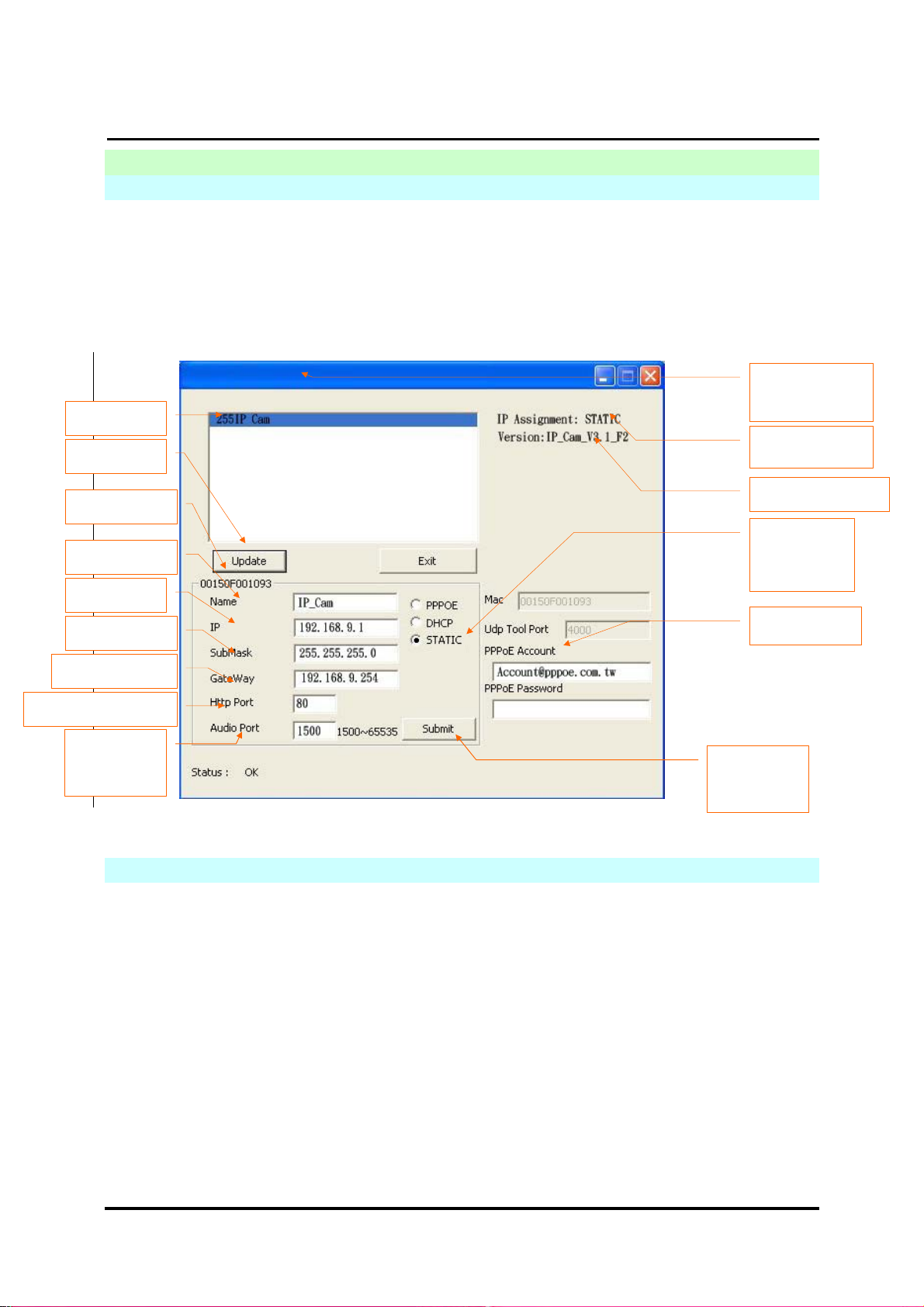
2.1 CAM_EZ SEARCH
CAM_EZ Search is an IP search engine offered by this product. It can search IP CAM
connected in LAN. Through sending the inquiry of broadcasting packets, after IP CAM
responds the question, the window will display a list of all IP CAMs in the network. And it
allows you to modify the network settings of specified IP CAM, such as IP address or IP
CAM naming.
CAM_EZ Search Screen
IP CAM List
Renew List
DN-16032 User’s Guide
PPaann//TTiilltt IIPP SSuurrvveeiillllaannccee CCaammeerra
Version of
CAM_EZ
Search
Display the way
et IP
to
a
MAC address
IP CAM Name
IP address
Subnet Mask
Default Gateway
Communication Port
Audio UDP
port
2.2 USE IP-CAM AND TEST THE IMAGE FUNCTION FOR THE FIRST TIME
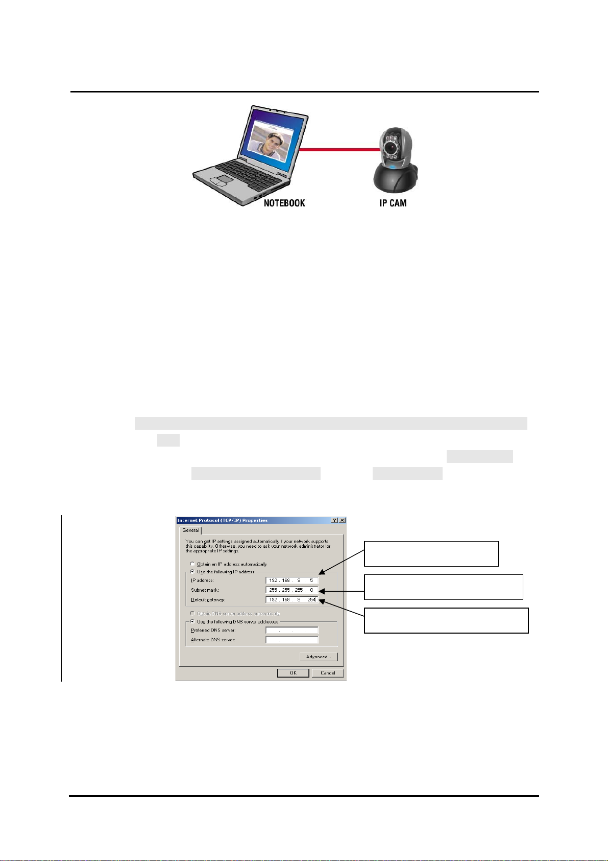
The following connection is suitable for IP-CAM test/fixed IP address change/program
code update (strongly recommended).
The operation steps are listed below:
Renew
executed to
obtain an IP
figure 1
A. Installing the Product for the first time:
You computer must be equipped with network card and RT-45 network
connector.
Connect the RJ-45 terminator on the rear of IP-CAM to the red test network
cable. One end is connected to the network card of computer; the other end
is connected to the rear side of the IP-CAM.
Connect the power adaptor to the power port (on the rear) of IP-CAM. Now,
the status LED on the top of IP-CAM will light up.
Version of IP CAM
Choose the
way to get IP
Key in PPPoE
DN-16032 USER’S GUIDE PAGE 8/61 Rev. PV1.0
Page 9
`
DN-16032 User’s Guide
PPaann//TTiilltt IIPP SSuurrvveeiillllaannccee CCaammeerra
B. Check if the IP addresses for PC network and CAM_EZ Search are on the
same network section:
Usually, static IP address will be used to access into Internet, so the IP
address will vary. When you want to change IP address, please write
down the original IP address on your computer first. Then you have to
modify the IP address of your computer for testing if the IP-CAM can be
operated normally or not. After finishing the test, IP address for your
computer should be recovered to original settings.
In general, the IP address for your computer in LAN will be set with
“Auto Obtain IP address”. To test if the IP-CAM is normal or not, the IP
address of your computer must be changed temporarily. After finishing
the test, it can be recovered to original settings.
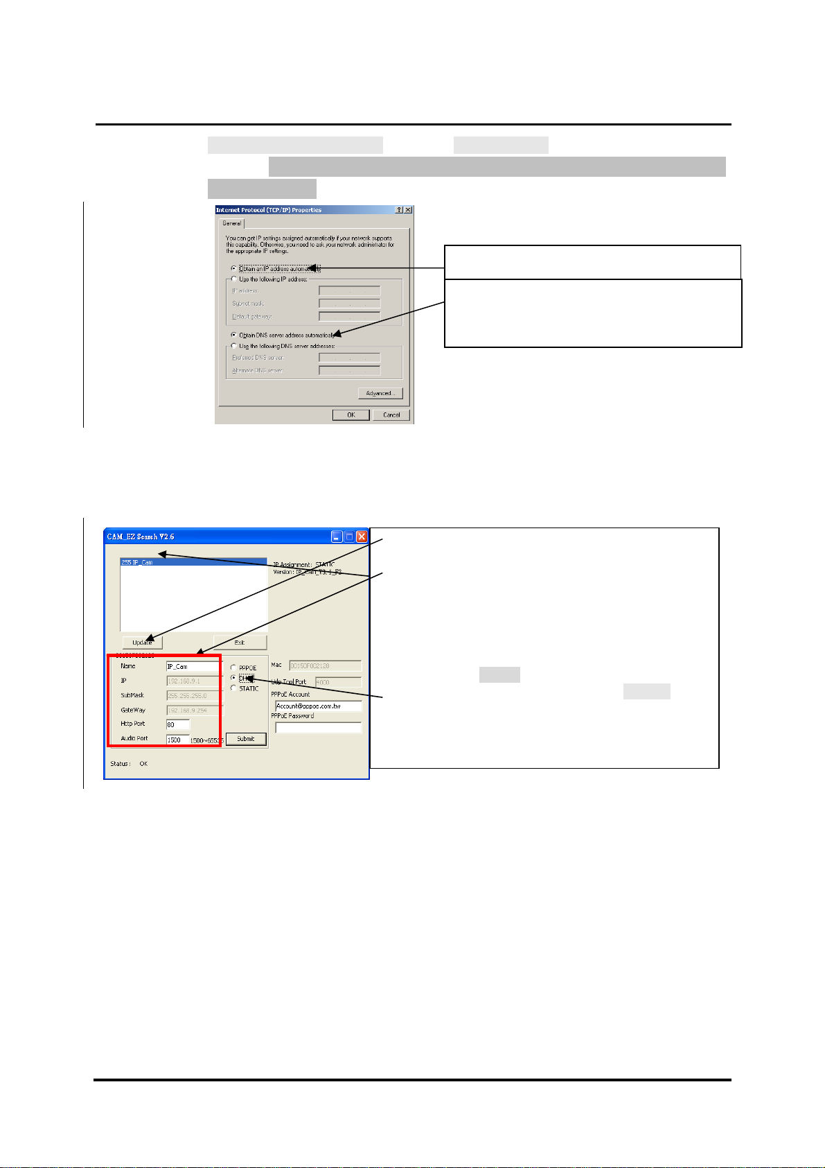
C. Next, choose Control Panel->Network Connections->choose the activated
area
Network Connections---> right click your mouse --->select Properties(P)--->
Select Internet Protocol (TCP/IP)---> Select Properties(R) , then you can
check the current IP address status for the computer. The way to modify IP
address is:
a
IP Address(I): 192.168.9.5
Subnet Mask (U):255.255.255.0
Default Gateway(D):192.168.9.254
D. Open and execute CAM_EZ Search (as shown in Figure 2). The system will
scan the IP-CAM that you just installed automatically. Then, you will find
255DN-16032 in the column of Camera Lists. Click 255DN-16032 with left
mouse button. You can see the default settings for IP-CAM.
DN-16032 USER’S GUIDE PAGE 9/61 Rev. PV1.0
Page 10
`
DN-16032 User’s Guide
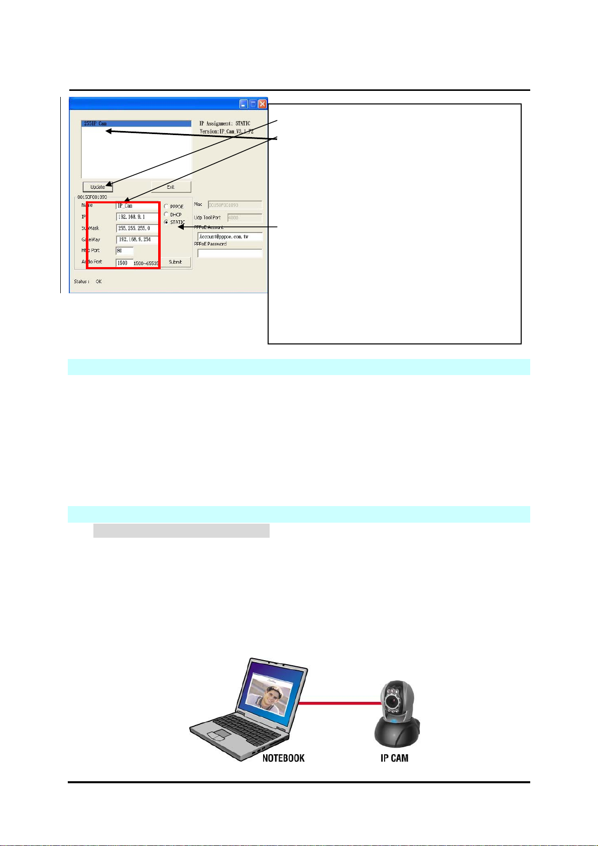
Step 1. Click Update. You can see 255DN-16032.
Step 2. Click 255DN-16032. You can see
Name : DN-16032
IP : 192.168.9.1
SubMask :255.255.255.0
GateWay :192.168.9.254
HTTP Port:Http communication port. The
default setting is 80.
UDP Port : UDP port, Pre-setting is 1500
Step 3. Make sure the IP setting is STATIC.
Step 4. Double click on 255DN-16032 to open the
Figure 2
browser. Type ID/Password to access into network
monitoring screen (for detailed information, please
refer to 3.1). If you can see the image screen, it
2.3 HOW TO SET UP IP CAM
Before you set up IP CAM, you have to know the network environment and if the IP
address is fixed or float that provided by your ISP. If you do not know, please contact with
your ISP. Section 2.5 will list the common network structure (1 ~ 7 types). Users can refer
to the structure to find out what type is suitable for his/her computer and finish the setting
up according to the instructions. To set up IP-CAM and IP address, the common way that
people use is to change the obtaining of IP address of IP-CAM. Detailed information is
listed as 2.4-1 ~ 2.4.3.
2.4 SETTING THE WAY TO OBTAIN THE IP ADDRESS OF IP-CAM
2.4-1 STATIC - IP Address Setting
You computer must be equipped with network card and RT-45 network
connector.
Connect the RJ-45 terminator on the rear of IP-CAM to the red test network
cable. One end is connected to the network card of computer; the other end
is connected to the rear side of the IP-CAM.
Connect the power adaptor to the power port (on the rear) of IP-CAM. Now,
the status LED on the top of IP-CAM will light up.
PPaann//TTiilltt IIPP SSuurrvveeiillllaannccee CCaammeerra
a
DN-16032 USER’S GUIDE PAGE 10/61 Rev. PV1.0
Page 11
`
g
Open and execute CAM_EZ Search (as shown in Figure 3). The system will
scan the IP-CAM that you just installed automatically. Then, you will find
255DN-16032 in the column of Camera Lists. Click 255DN-16032 with left
mouse button. You can see the default settings for IP-CAM.
Figure 3
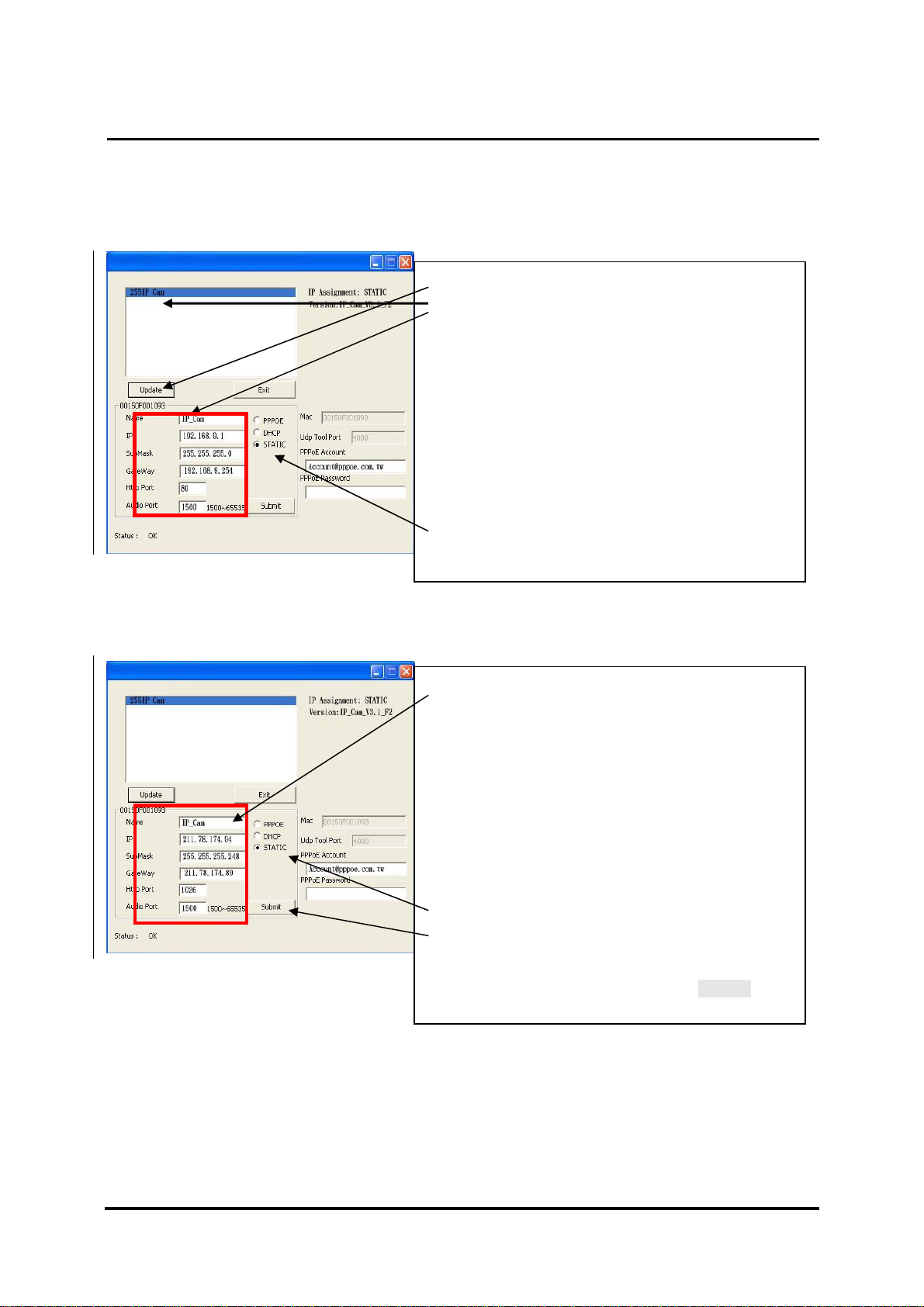
Fill in Fixed IP Address as below. (If you do not know your fixed IP address,
please contact with your ISP. Below is an example of Fixed IP Address
modification.)
DN-16032 User’s Guide
Step 1. Click Update. You can see 255DN-16032.
Step 2. Click 255DN-16032. You can see
Name : DN-16032
IP : 192.168.9.1
SubMask :255.255.255.0
GateWay :192.168.9.254
HTTP Port:Http communication port. The
default setting is 80.
(If you have multiple IP-CAMs installed in
the same network, you have to divide them with
different Port numbers, e.g, 1025、1026、1039….)
Step 3. Make sure the IP setting is STATIC.
UDP Port : UDP port,Pre-setting is 1500
PPaann//TTiilltt IIPP SSuurrvveeiillllaannccee CCaammeerra
a
Step 4. Type Fixed IP.
Name : DN-16032
IP : 211.78.174.94
SubMask :255.255.255.248
GateWay :211.78.174.89
HTTP Port:Http communication port. The
default setting is 80.
(If you have multiple IP-CAMs installed in the
same network, you have to divide them
with different Port numbers, e.g, 1025、
1026、1039…..)
Step 5. Choose STATIC.
Step 6. After finishing the settings, click Submit. The
UDP Port : UDP Port,Pre-setting is 1500
network settin
s for DN-16032 IP-CAM will
DN-16032 USER’S GUIDE PAGE 11/61 Rev. PV1.0
Page 12
`
DN-16032 User’s Guide
PPaann//TTiilltt IIPP SSuurrvveeiillllaannccee CCaammeerra
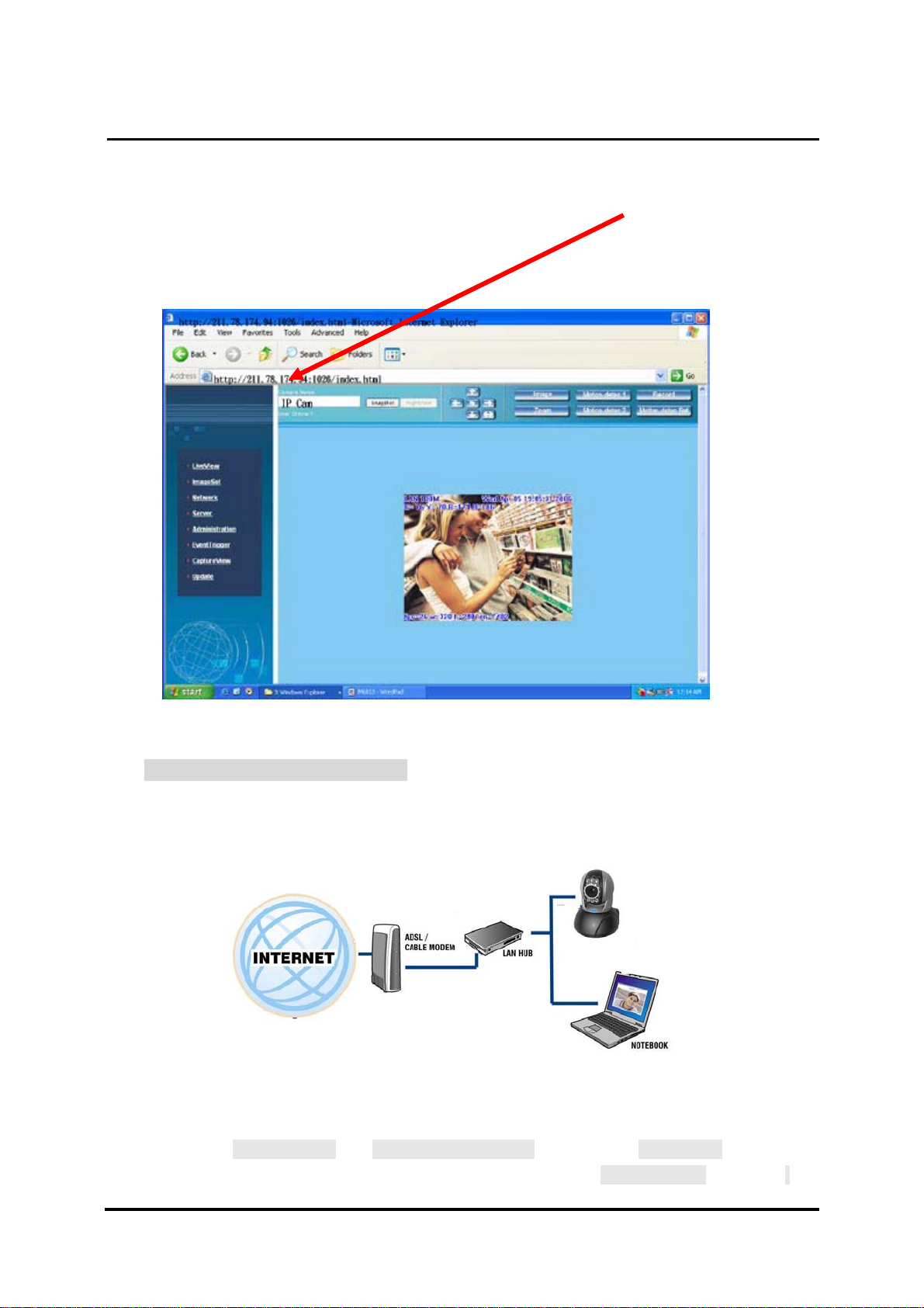
Example:
1. Set up the IP CAM with fixed IP address.
2. Turn on your computer and open IE browser. Type 211.78.174.94:(
1026、1039….)
in the Address line. Now you can access into the monitoring
screen of network.
1025、
a
2.4-2 DHCP - IP Address Setting:
Use RJ-45 Ethernet cable (red) to connect ADSL host and switching hub.
Then use RJ-45 Ethernet cable (blue) to connect PC and IP CAM (as shown
below).
Connect the power adaptor to the power port (on the rear) of IP-CAM. Now,
the status LED on the top of IP-CAM will light up.
Set up the connection way inside the PC network: Please go to
Control Panel ---> Network Connections ---> Choose Activated LAN
connection ---> right click your mouse ---> Select Properties(P)---> Select
DN-16032 USER’S GUIDE PAGE 12/61 Rev. PV1.0
Page 13
`
DN-16032 User’s Guide
PPaann//TTiilltt IIPP SSuurrvveeiillllaannccee CCaammeerra
Internet Protocol (TCP/IP)---> Select Properties(R)
--->Click Obtain an IP address automatically(O), Obtain DNS server address
automatically(B).
Obtain an IP address automatically (O)
Obtain DNS server address
automatically (B)
a
Open and execute CAM_EZ Search (as shown in Figure 3). Press Update
to scan the IP-CAM that you just installed automatically. Then, you will find
255DN-16032 in the column of Camera Lists. Click 255DN-16032 with left
mouse button. You can see the default settings for IP-CAM.
Step 1. Click Update. You can see 255DN-16032.
Step 2. Click 255DN-16032. You can see
Name : DN-16032
IP : 192.168.9.1
SubMask :255.255.255.0
GateWay :192.168.9.254
HTTP Port:Http communication port. The
default setting is 80.
Step 3. Choose DHCP.
Step 4. After finishing the settings, click Submit. The
network settings for DN-16032 IP-CAM will be
renewed. (That is, you can obtain a virtual IP
address)
DN-16032 USER’S GUIDE PAGE 13/61 Rev. PV1.0
Page 14
`
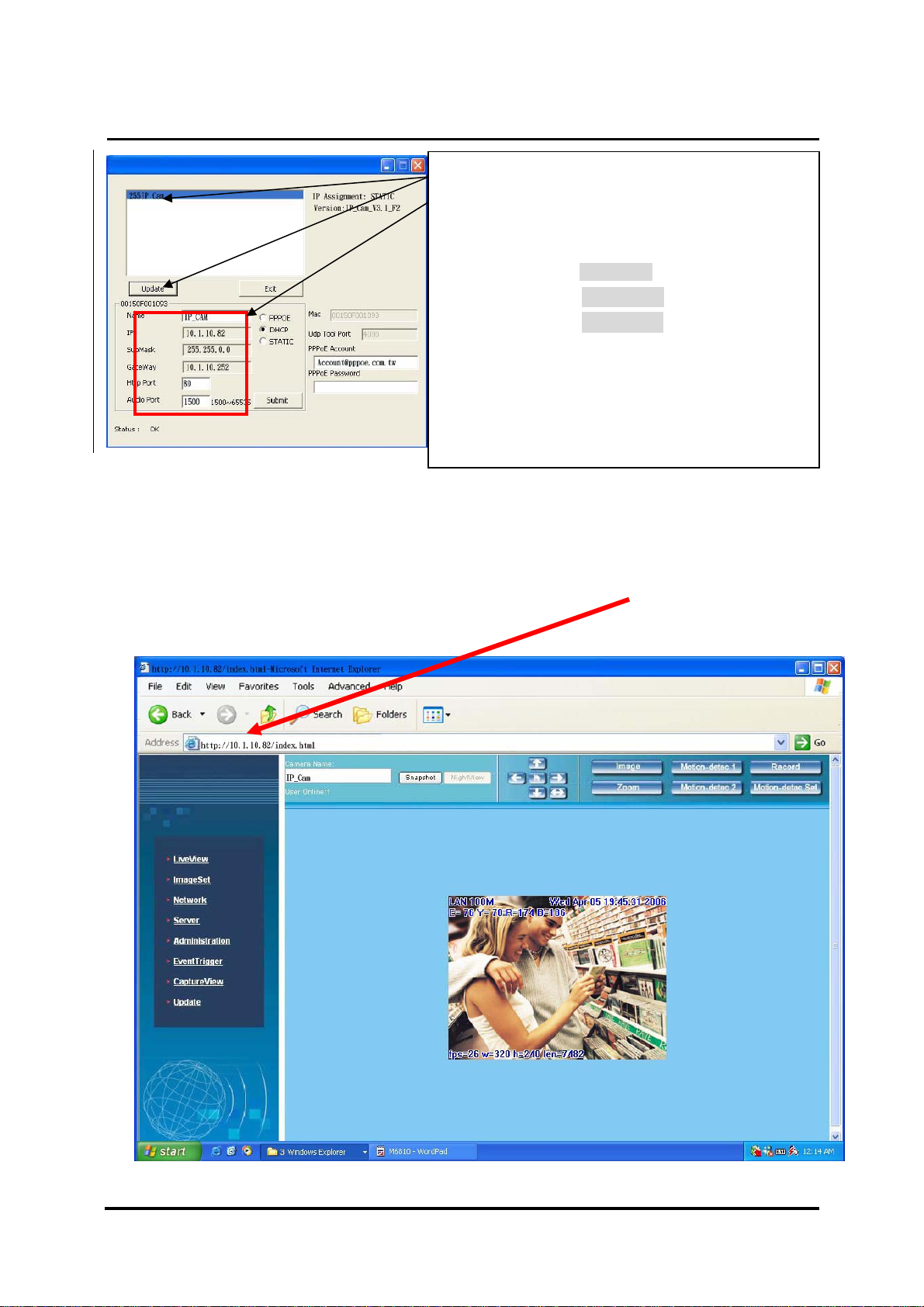
Figure 5
Example:
DN-16032 User’s Guide
Step 5. Click Update. You can see 255DN-16032.
Step 6. Click 255DN-16032. You can see the change
of IP-CAM:
Name : DN-16032
IP : 10.1.10.82
SubMask :255.255.0.0
GateWay :10.1.10.252
HTTP Port:Http communication port. The
default setting is 80.
Step 7. The IP setting is DHCP.
Step 8. Double click 255DN-16032 to open IE
browser to access into network monitoring
1. Now, IP-CAM is set up with the IP address in LAN.
2. Or, use CAM_EZ Search to access into monitoring screen of network
according to the instructions in Figure 5.
3. Or, turn on your PC and open IE Browse. Type 10.1.10.82 in Address lint
to access into monitoring screen of network.
PPaann//TTiilltt IIPP SSuurrvveeiillllaannccee CCaammeerra
a
DN-16032 USER’S GUIDE PAGE 14/61 Rev. PV1.0
Page 15
`
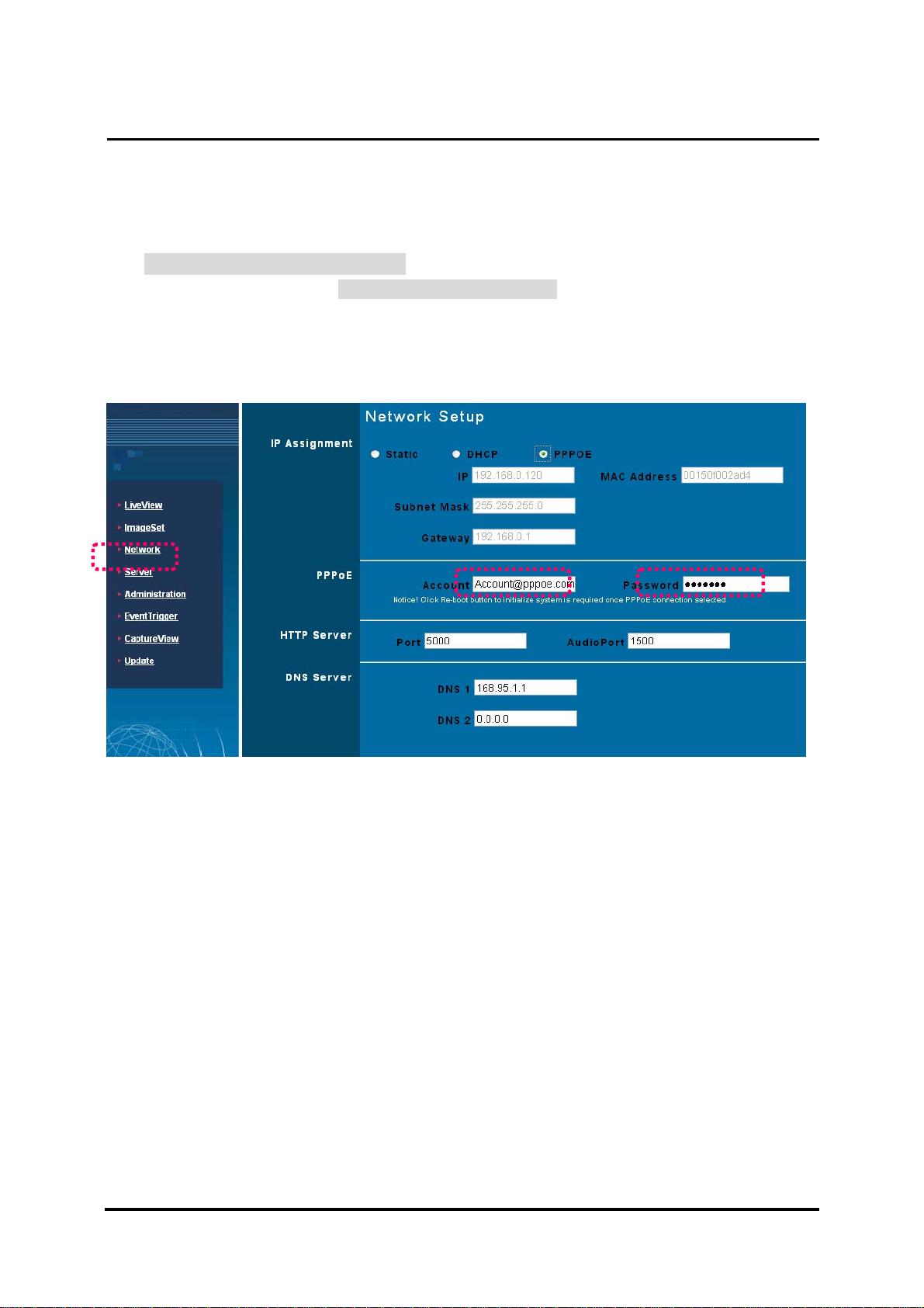
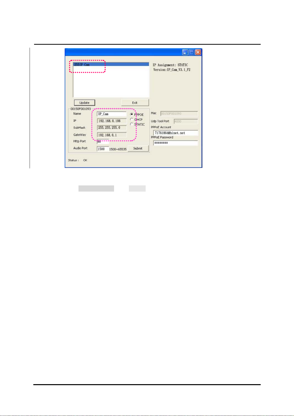
2.4-3 PPPoE - IP Address Setting
Access into monitoring screen of network by following the way stated in 2.2.
Click Network and open Network menu. Please choose PPPoE and key in
the Account and Password. (the following example uses ADSL account from
AT&T), press Submit to finish key in and then, please reboot and re-enter.
DN-16032 User’s Guide
PPaann//TTiilltt IIPP SSuurrvveeiillllaannccee CCaammeerra
a
Open CAM_EZ Search and click Update. Wait for 60 seconds (it varies
according to the connection quality). Then the system will search DN-16032
IP-CAM automatically. 1. Click the searched IP-CAM. 2. Check the IP
address and Gateway. Floating IP address, SubMask and Gateway will be
shown in dimmed color. It means that DN-16032 IP-CAM in LAN has been
searched successfully with PPPoE.
DN-16032 USER’S GUIDE PAGE 15/61 Rev. PV1.0
Page 16
`
DN-16032 User’s Guide
PPaann//TTiilltt IIPP SSuurrvveeiillllaannccee CCaammeerra
a
1.
2.
3. You can also directly use CAM_EZ Search and key in PPPoE Account &
Password.
Select PPPoE. Click Submit to send out. The DN-16032 IP-CAM network
settings will be renewed.
Now you can click the searched IP-CAM to open IE Browser for accessing
into IP-CAM web configurator automatically.
DN-16032 USER’S GUIDE PAGE 16/61 Rev. PV1.0
Page 17
`
DN-16032 User’s Guide
2.5 IP-CAM NETWORK FRAMEWORK INSTALLATION
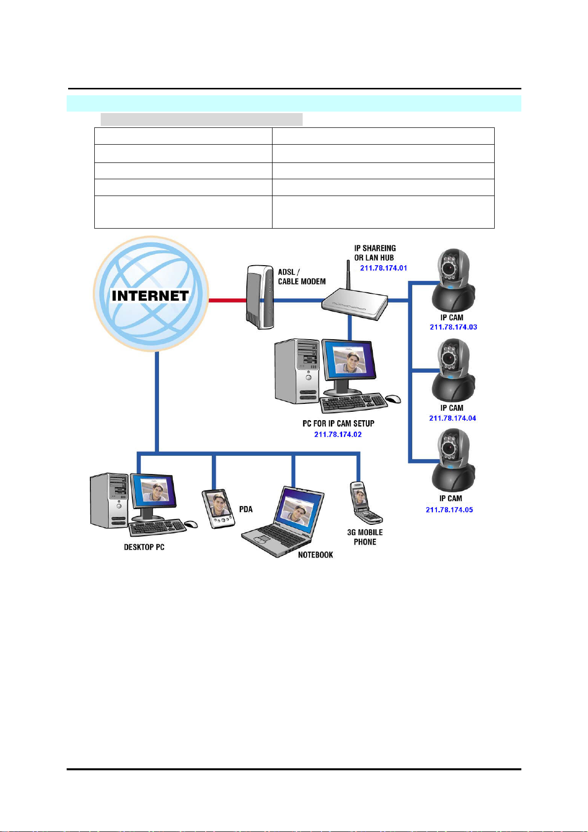
一. IP-CAM Network Framework Installation 1
Way to access Internet Use Permanent ADSL or Cable Modem
Physical IP Address Owns several physical IP addresses
IP Share or LAN Hub General model is OK.
Network Setup for IP -CAM LAN Enable / Manually
Suitable Objects Users with several physical fixed IP
addresses and several IP-CAMs installed
PPaann//TTiilltt IIPP SSuurrvveeiillllaannccee CCaammeerra
a
1. Connect the RJ-45 terminator on the rear of IP-CAM to the red test network cable.
One end is connected to the network card of computer; the other end is connected
to the rear side of the IP-CAM.
2. Refer to 2.4-1 STATIC – IP Address Settings to type the IP address properly.
3. Set a physical IP address for each IP-CAM.
4. Set up the IP-CAM with fixed IP address.
5. For viewing images in IP-CAM from remote computer: Open IP browser and type
in the physical IP address of the IP-CAM, e.g., http://211.78.174.03.
DN-16032 USER’S GUIDE PAGE 17/61 Rev. PV1.0
Page 18
`
DN-16032 User’s Guide
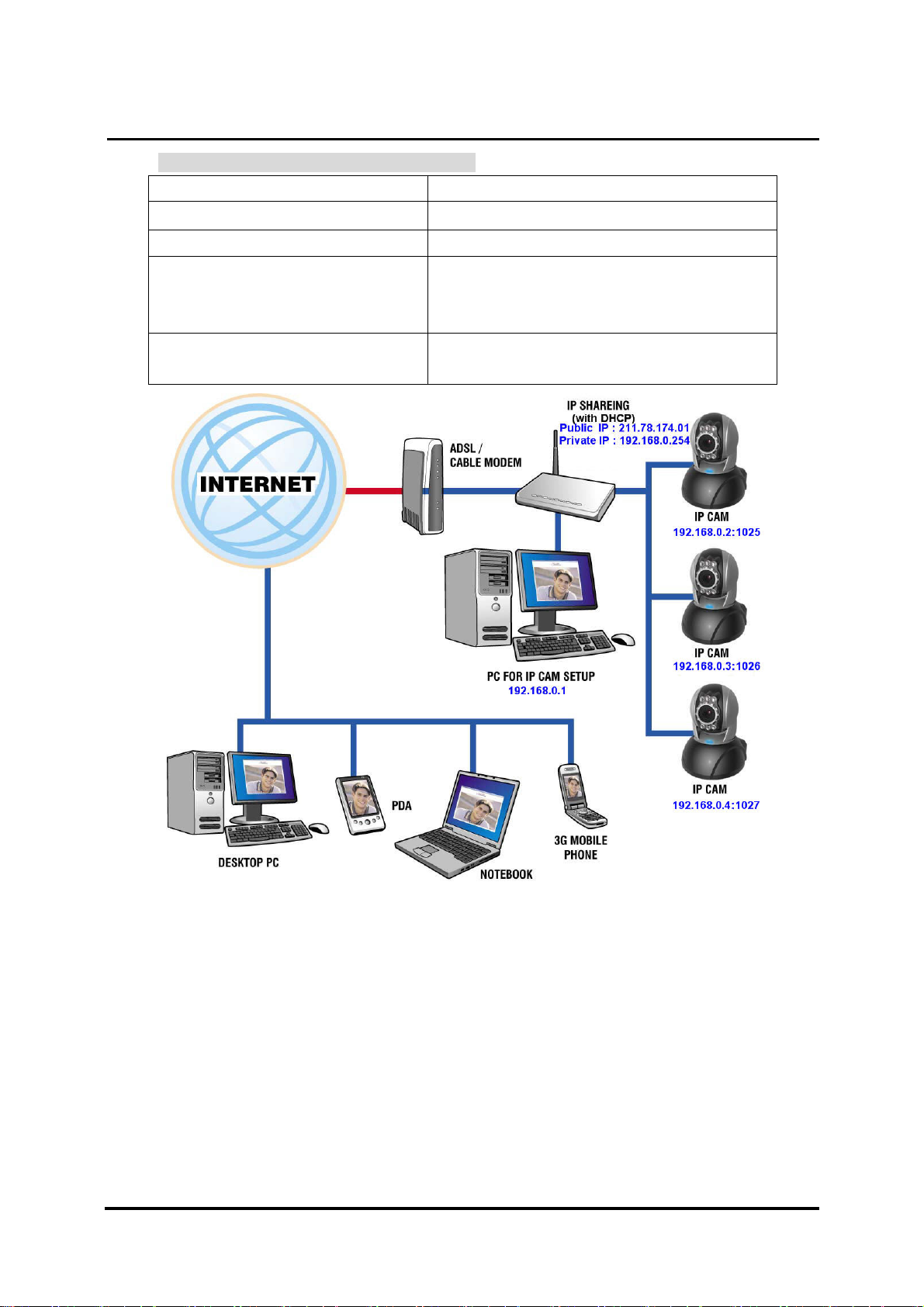
二. IP-CAM Network Framework Installation 2
Way to access Internet Use Permanent ADSL or Cable Modem
Physical IP Address Owns more than one IP address
IP Share or LAN Hub Must be equipped with DHCP function
Network Setup for IP -CAM LAN Enable / Manually
Web Server Port Number, need to be
adjusted
Suitable Objects Users with one physical fixed IP addresses,
IP Share and several IP-CAMs installed
PPaann//TTiilltt IIPP SSuurrvveeiillllaannccee CCaammeerra
a
1. Set a real physical IP address (e.g., 211.78.174.01) for the public IP of IP Share.
Then, set another private IP address and activate the DHCP server function of IP
Share.
2. In the IP configuration for each IP-CAM, please assign different virtual IP address
internally and respectively. In the Http Port setting, please specify different port
parameters. (Please refer to 2.4-1 STATIC - IP Address Settings to type the IP
address properly.)
3. For the port transformation in IP Share, please refer to IP and port settings of camera
to configure accordingly.
4. For viewing images in IP-CAM from remote computer: Open IP browser and type in
the physical IP address of the IP Share and the port number of IP-CAM, e.g., http://
211.78.174.01:1025.
DN-16032 USER’S GUIDE PAGE 18/61 Rev. PV1.0
Page 19
`
DN-16032 User’s Guide
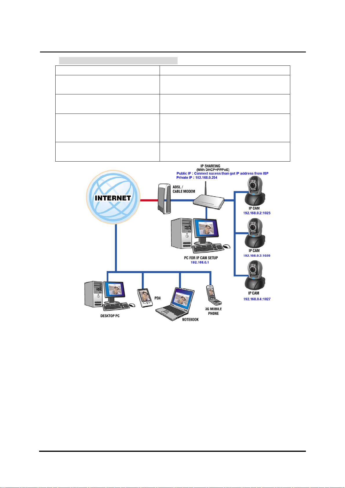
三. IP-CAM Network Framework Installation 3
Way to access Internet Use dial-up ADSL or Cable Modem
Physical IP Address Owns one float IP address (dispatched by
ISP dynamically)
IP Share or LAN Hub Must be equipped with DHCP and NAT
functions
Network Setup for IP -CAM LAN Enable / Manually
Web Server Port Number, need to be
adjusted
Suitable Objects Users with dial-up ADSL, one float IP address
and several IP-CAMs installed
PPaann//TTiilltt IIPP SSuurrvveeiillllaannccee CCaammeerra
a
1. Activate PPPoE function of IP share. Then, set another private IP address and
activate the DHCP server function of IP Share. When the dial-up of ADSL is
successful, you will get an float IP address from your ISP.
2. In the IP configuration for each IP-CAM, please assign different virtual IP address
internally and respectively. In the Http Port setting, please specify different port
parameters. (Please refer to 2.4-1 STATIC - IP Address Settings to type the IP
address properly.)
3. For the port transformation in IP Share, please refer to IP and port settings of camera
to configure accordingly.
4. For viewing images in IP-CAM from remote computer: Open IP browser and type in
the float IP address of ADSL and the port number of IP-CAM, e.g., http://
211.78.174.01:1025.
DN-16032 USER’S GUIDE PAGE 19/61 Rev. PV1.0
Page 20

`
DN-16032 User’s Guide
四. IP-CAM Network Framework Installation 4
Way to access Internet Use Permanent ADSL or Cable Modem
Physical IP Address Owns one physical IP address
IP Share or LAN Hub Not necessary
Network Setup for IP -CAM LAN Enable / Manually
Web Server Port Number, no need to be
adjusted
Suitable Objects Users with permanent ADSL, one fixed
physical IP address and one IP-CAM installed
PPaann//TTiilltt IIPP SSuurrvveeiillllaannccee CCaammeerra
a
1. Connect the RJ-45 terminator on the rear of IP-CAM to the red test network cable.
One end is connected to the network card of computer; the other end is connected
to the rear side of the IP-CAM.
2.
Refer to 2.4-1 STATIC – IP Address Settings to typing the IP address properly.
3. Set up the IP-CAM with fixed IP address.
For viewing images in IP-CAM from remote computer: Open IP browser and type
4.
in the physical IP address of the IP-CAM, e.g., http://211.78.174.94.
DN-16032 USER’S GUIDE PAGE 20/61 Rev. PV1.0
Page 21

`
DN-16032 User’s Guide
五. IP-CAM Network Framework Installation 5
Way to access Internet Use dial-up ADSL or Cable Modem
Physical IP Address Owns one float IP address (dispatched by
ISP dynamically)
IP Share or LAN Hub Not necessary
Network Setup for IP -CAM PPPoE function should be set, LAN Enable
Web Server Port Number, no need to be
adjusted
Suitable Objects Users with dial-up ADSL, and one IP-CAM
installed
PPaann//TTiilltt IIPP SSuurrvveeiillllaannccee CCaammeerra
a
1. Please acquire the necessary information of ADSL dial-up from your ISP.
ISP relational information: ADSL dial-up account name and password
2. Connect the RJ-45 terminator on the rear of IP-CAM to the red test network cable.
One end is connected to the network card of computer; the other end is connected to
the rear side of the IP-CAM.
3. Refer to 2.4-3 PPPoE - IP Address Settings for typing account name and
password.
4. Please type the Mail server setup information of IP-CAM.
5. Set up the IP-CAM to
Dial up ADSL Modem.
6. When the dial-up is successful, IP-CAM will send a notification e-mail of float IP
Address to the users.
7. Open IP browser and type in the physical IP address (such float IP is dispatched by
ISP) of the IP-CAM, e.g., http://211.78.174.94.
DN-16032 USER’S GUIDE PAGE 21/61 Rev. PV1.0
Page 22

`
DN-16032 User’s Guide
六. IP-CAM Network Framework Installation 6
Way to access Internet Use dial-up ADSL or Cable Modem
Physical IP Address Owns several float IP addresses
(dispatched by ISP dynamically)
IP Share or LAN Hub Must be equipped with DHCP and NAT
functions
Network Setup for IP -CAM LAN Enable / Manually
Web Server Port Number, need to be
adjusted
Suitable Objects Users with several float IP addresses and
several IP-CAMs installed
PPaann//TTiilltt IIPP SSuurrvveeiillllaannccee CCaammeerra
a
1. Please acquire the necessary information of ADSL dial-up from your ISP.
ISP relational information: ADSL dial-up account name and password
Connect the RJ-45 terminator on the rear of IP-CAM to the red test network cable.
2.
One end is connected to the network card of computer; the other end is connected to
the rear side of the IP-CAM.
3.
Refer to 2.4-3 PPPoE - IP Address Settings for typing account name and
password.
4. Please type the Mail server setup information of IP-CAM.
5. Install IP-CAM on LAN Hub.
6. Use CAM_EZ Search tool to find out the float IP address assigned by ISP for the
ADSL currently.
7. Open IP browser and type in the physical IP address (such float IP is dispatched by
ISP) of the IP-CAM, e.g., http://211.78.174.94.
8. Follow the steps above to configure for each IP-CAM.
DN-16032 USER’S GUIDE PAGE 22/61 Rev. PV1.0
Page 23

`
DN-16032 User’s Guide
七. IP-CAM Network Framework Installation 7
Way to access Internet Use Permanent ADSL or Cable Modem
Physical IP Address Owns one physical IP address
IP Share or LAN Hub Must be equipped with DHCP and NAT
functions
Network Setup for IP -CAM LAN Enable / Manually
Web Server Port Number, need to be
configured
Suitable Objects Users with one fixed physical IP, IP Share
and several IP-CAMs installed
PPaann//TTiilltt IIPP SSuurrvveeiillllaannccee CCaammeerra
a
1. Set a real physical IP address (e.g., 211.78.174.01) for the public IP of IP Share.
Then, set another private IP address and activate the DHCP server function of IP
Share.
2. In the IP configuration for each IP-CAM, please assign different virtual IP address
internally and respectively. In the Http Port setting, please specify different port
parameters. (Please refer to 2.4-1 STATIC - IP Address Settings to fill in the IP
address properly.)
3. For the port transformation in IP Share, please refer to IP and port settings of camera
to configure accordingly.
4. For viewing images in IP-CAM from remote computer: Open IP browser and type in
the IP address of IP Share and the port number of IP-CAM, e.g., http://
211.78.174.01:1025.
DN-16032 USER’S GUIDE PAGE 23/61 Rev. PV1.0
Page 24

`
DN-16032 User’s Guide
2.6 INSTALLATION FOR IP SHARE
When IP-CAM is installed under IP Share, it can obtain a dynamic IP address from DHCP
server. If you want to install the IP-CAM in WAN interface, you have to set a fixed IP address
for the device. No matter whether your IP Share has the function of virtual server, it is
necessary for IP-CAM to set a fixed IP address.
(1) Please use CAM_EZ Search to set a fixed IP address for IP-CAM, e.g.,
192.168.0.120 and change the http port number (1025~35534). (refer to Figure
1)
Figure 1
PPaann//TTiilltt IIPP SSuurrvveeiillllaannccee CCaammeerra
a
(2) Type admin to access into ADSL router’s web configuration. (Refer to Figure 2)
Figure 2
DN-16032 USER’S GUIDE PAGE 24/61 Rev. PV1.0
Page 25

`
DN-16032 User’s Guide
(3) Enable DHCP function of IP Share. (Refer to Figure 3. The range of available IP address is
192.168.0.100~192.168.0.199)
PPaann//TTiilltt IIPP SSuurrvveeiillllaannccee CCaammeerra
Figure 3
a
(4) Access into the web page of Virtual Server. Add the fixed IP address specified by CAM_EZ
Search in step (1) and enable it. (Refer to Figure 4.1)
Figure 4.1
DN-16032 USER’S GUIDE PAGE 25/61 Rev. PV1.0
Page 26

`
DN-16032 User’s Guide
(5) After adding the IP address, you can see jeffipcam1 in the virtual server list (refer to
Figure 4.2).
PPaann//TTiilltt IIPP SSuurrvveeiillllaannccee CCaammeerra
Figure 4.2
a
(6) Restart PC and IP Share. After restarting, if you want to connect IP-CAM from WAN
interface, please go to Status\WAN\IP Address of the router’s web configurator.
(http://59.104.28.251:5000, refer to Figure 5)
Figure 5
DN-16032 USER’S GUIDE PAGE 26/61 Rev. PV1.0
Page 27

`
DN-16032 User’s Guide
2.7 INTERNET IP SHARING & AUDIO SETTING
Please use the following steps for setting up if your IP cam does not have Audio
Step 1, setting Audio Part : the Pre-setting is 1500 (setting range is 1500~65535) and
press Submit
PPaann//TTiilltt IIPP SSuurrvveeiillllaannccee CCaammeerra
a
step 2, add one new UDP part 1500 in router (UDP port setting range is 1500~65535) as
one port can only appoint to the use of one IP cam. Therefore, please assign other
ports if you have more than two IP cams.
DN-16032 USER’S GUIDE PAGE 27/61 Rev. PV1.0
Page 28

`
DN-16032 User’s Guide
3. GETTING STARTED
3.1 SYSTEM LOGIN
The system login is the process of identifying all users trying to log into the system to
confirm user identify and grant permission to access to the system’s functions. This
system provides two layers of security access: “administer” and “general user”. After a
successful login to the system, users can begin to access both surveillance and setting
functions, Follow the steps below to log in as an ”admin” user:
Step 1: Open the login window, as shown below.
Using the CAM_EZ Search application, select the DN-16032 from the menu, and Double
Click on it ; .
PPaann//TTiilltt IIPP SSuurrvveeiillllaannccee CCaammeerra
1.
a
Step 2: The system login window will appear in Internet Explorer as shown below:
Step 3: Enter Account ID and Password (the default settings are “admin” and
“password”);
Step.4 Press Submit to confirm, and then follow the instructions for the
feature show on the next page ;
Step.5 If a mistake has been made, press Cancel, and enter login information again.
DN-16032 USER’S GUIDE PAGE 28/61 Rev. PV1.0
Page 29

`
DN-16032 User’s Guide
3.2 LIVEVIEW
When using IP Cam for the first time, users must change the Internet Explorer security
settings (please refer to settings step 3.2.1
). Otherwise, the system will display the
following warning, and be unable to display the surveillance feeds.
PPaann//TTiilltt IIPP SSuurrvveeiillllaannccee CCaammeerra
a
After having successfully set up the IP CAM settings during the first use, users do not
need to change the settings again for later use.
3.2.1 The IE security settings can be changed by following the steps below:
Step 1. IE Toolbar ---> Tools ---> Internet Options ---> Security ---> Custom Level …
DN-16032 USER’S GUIDE PAGE 29/61 Rev. PV1.0
Page 30

`
DN-16032 User’s Guide
PPaann//TTiilltt IIPP SSuurrvveeiillllaannccee CCaammeerra
Step 2. After clicking on Custom Level …, a security settings window shall appear.
Change ActiveX Control Options and Plug-ins settings to the following:
1. Download signed ActiveX controls: Enable
2. Download unsigned ActiveX controls: Enable
3. Initialize and script ActiveX controls not marked as safe: Enable
4. Run ActiveX controls and plug-ins: Enable
5. Script ActiveX controls marked safe for scripting: Enable
a
Step 3. After pressing “ok”, a warning window shall appear. Click on “Yes” , and you
shall return to the last window. Press “OK”, and the setup is complete.
DN-16032 USER’S GUIDE PAGE 30/61 Rev. PV1.0
Page 31

`
DN-16032 User’s Guide
PPaann//TTiilltt IIPP SSuurrvveeiillllaannccee CCaammeerra
Step 4. At this time, the computer should display a warning window, as shown above :
Press “Yes” , to begin;
Step 5. When the installation is complete, you may begin viewing the surveillance
image for the first time, as shown below.
a
DN-16032 USER’S GUIDE PAGE 31/61 Rev. PV1.0
Page 32

`
DN-16032 User’s Guide
PPaann//TTiilltt IIPP SSuurrvveeiillllaannccee CCaammeerra
Note: This action loads ActiveX components from the DN-16032 System to the local machine.
To ensure your machine cannot run malicious ActiveX content from the Internet without
authorization, you will be prompted to allow the ActiveX component of your browser to interact
with the Rimax DN-16032 each time you access it. When you view the stream from the IP Cam
and you see the prompts regarding downloading, running or enabling ActiveX content from the
IP address of the DN-16032, click “Yes” to allow your computer to display the video from your
camera .If you are prompted to allow ActiveX content when you are not connected to your
DN-16032, ensure the provider of the content is a reliable and secure source for running
programs on your PC. If you are in doubt about the source of the ActiveX program you are
being requested to allow to run on your system, click “No” to ensure you don’t allow malicious
programs to interfere with your PC.
3.3 TAKE A SHOT
This function allows users to capture the screenshot as a photo, and save it on the
computer.
Directions:
a
Step 1. Go to the
menu, and go to the live image.
Step 2: Hold down the Ctrl key on your keyboard;
Step 3. Place the cursor on the surveillance image and left click with your mouse. The
captured image should flash momentarily, as shown below:
(or press the
button)
DN-16032 USER’S GUIDE PAGE 32/61 Rev. PV1.0
Page 33

`
DN-16032 User’s Guide
PPaann//TTiilltt IIPP SSuurrvveeiillllaannccee CCaammeerra
Step 4. Release the Ctrl key, and the single still shot image will have been successfully
captured.
a
Step 5. Select the
menu to browse through the captured images. Refer to
Chapter 5.2 for details.
Note: Snapshot can only be stored to PC, can't store to SD Card
4. ADVANCED FUNCTION WITH LIVEVIEW
Move the cursor to the live image, and right click with your mouse. A small menu should appear
with four options.
- Image:Adjust image values
- Record:Setup for recording into AVI format.
- Zoom:Select digital zoom value for window.
- Motion Detect Set:Settings for motion detection
These settings are described in detail in the next chapter
4.1 IMAGE ADJUSTMENT
After selecting an Image, you may change various image settings, as shown below:
( )
DN-16032 USER’S GUIDE PAGE 33/61 Rev. PV1.0
Page 34

`
DN-16032 User’s Guide
4.2 AVI RECORD SETUP
By selecting “Record”, you can adjust the AVI Frame Rate settings ad file name.
PPaann//TTiilltt IIPP SSuurrvveeiillllaannccee CCaammeerra
a
(
):
DN-16032 USER’S GUIDE PAGE 34/61 Rev. PV1.0
Page 35

`
DN-16032 User’s Guide
4.3 ZOOM IN DISPLAY
Using your mouse, click and drag out a box to select the portion of video that you wish to
view as shown by the grey box in the image below. The image will zoom in according to
PPaann//TTiilltt IIPP SSuurrvveeiillllaannccee CCaammeerra
a
the dimensions entered and will show an image similar to this below (
):
4.4 MOTION DETECTION SETUP
Setting up the Motion Detection (MD) values, including the first area (red border) and
second area (green border).
Please check to see whether the Event Trigger has been enabled. If so, you can set up
Motion Detection as described below:
- Reset MD range: Select motion detect 1or2, and hold down on the left mouse button
(this will appear as the upper left corner of the MD range). Then, drag out the desired
range, and release when finished.
- Cancel MD: Same as above, but just left click once and release. This will cancel the
MD (Motion Detection).
DN-16032 USER’S GUIDE PAGE 35/61 Rev. PV1.0
( 、 )
Page 36

`
DN-16032 User’s Guide
- Motion_detec_set: This sets the MD (Motion Detection) sensitivity, which is usually set
to a value of 5. This means that the motion detection will be toggled with as little of a
5% change in the MD range. The lower the number entered, the higher the sensitivity
PPaann//TTiilltt IIPP SSuurrvveeiillllaannccee CCaammeerra
a
of the MD.
When motion is detected, the screen should display an MD warning in red in the upper
left hand corner if there is movement within MD1 or MD2, as shown in below:
- Any motion detection range can be selected in 640x480 and 320x240 resolutions
- In 160x120 resolution, the motion detection is fixed to the entire image.
( )
Note:
1. Motion Detection can exist PC and SD Card
2. Image that MD reaches PC is stored to C: \tmp\webmd
4.5 MOTOR CONTROL
1. — Home , return to the middle place.
2.
— Up , press it to move up.
3. — Down , press it to move down.
4.
— Left press it to move left.
5. — Right , press it to move right.
6. — Detection , After press the bottom, IP Cam will detect horizon automatically
5. ADVANCED APPLICATION
This chapter explains the advanced settings for the DN-16032, including:
- Image Setup
- Capture View
- Network Setup
- Server Setup
- Event Trigger Setup
- Administration Setup
- Software Update
DN-16032 USER’S GUIDE PAGE 36/61 Rev. PV1.0
Page 37

`
DN-16032 User’s Guide
5.1 IMAGE SETUP
This includes:
- Resolution:Users can select between image resolution of 160x120, 320x240, and
640x480. The default resolution is 320x240.
- Quality: Users can select between “fine”, “normal”, and “basic” image quality. The
default image quality is “basic”.
- Anti-Flicker:Users can select between 60Hz for USA and Canada, 50Hz for Australia
and Europe, or Outdoor for when you are observing a naturally lit outside area; The
default setting is 50Hz.
- Audio:Audio output. Default setting is “off”.
- Rotate 180:This setting turns the image upside-down for when the camera is mounted
to a ceiling; Default setting is “off”.
- IR Auto Detection:IR LED auto activation in low light. Default setting is “on”
- Message : LiveView characters are hidden,
Image Setup Directions:
Default setting is “on”
PPaann//TTiilltt IIPP SSuurrvveeiillllaannccee CCaammeerra
a
Step 1. Click on
to view the menu, the default settings are shown below;
Step 2. After entering the desired values, click on Submit.
Step 3. If you wish to cancel your changes, click on Cancel
5.2 CAPTURE VIEW
This view includes:
- Manual capture of still images using LiveView.
Automatic capture of still images via MD.
-
How to Use Capture View:
Step 1. Click on
DN-16032 USER’S GUIDE PAGE 37/61 Rev. PV1.0
to enter the menu. The menu is capable of saving up to
Page 38

`
DN-16032 User’s Guide
48 images, viewable on three pages of. Images saved using Motion Detection will not be
shown here;
PPaann//TTiilltt IIPP SSuurrvveeiillllaannccee CCaammeerra
a
Step 2. You can set the system to read from either your computer or your SD Memory
card. After making your selection, click on Apply.
Step 3. Select desired thumbnail image using the cursor to view image at the default
dimensions.
Note: Images seen in : PC is the image of Snapshot; FlashCard is the image
of MD; The image of MD to PC is stored in C:\tmp\webmd
5.3 EVENT TRIGGER
This includes both event trigger settings and display, including:
- Event: Entering events
- Trigger:Setting trigger and picture capture times
DN-16032 USER’S GUIDE PAGE 38/61 Rev. PV1.0
Page 39

`
DN-16032 User’s Guide
Detailed explanations are presented in the next chapter.
5.3.1 Event
Event settings, including:
- Motion Detection (set 1)
- Motion Detection (set 2)
Individual or both set signal input triggers can be seleced.
How to Use Event Settings:
Step 1. Activate Event for either set (MD will automatically display the trigger sensitivity)
Step 2. After you are finished, click on Submit, otherwise;
Step 3. Click on Default to use factory default settings (sets all to off).
Note: After engaging either type of event, “Save in PC” will automatically turn on.
5.3.2 Trigger
Event trigger image transfer settings, including:
- Save in PC:The image file is saved in your computer.
- Save in Flash Card:The image file is saved in the SD card.
- Mail Image:Send captured event trigger image file by e-mail.
- FTP Image: Send captured event trigger image file by FTP.
- Shutter Timer:Change shutter time for event trigger image capture. two (2) seconds is
the default setting.
5.4 NETWORK SETUP
Network Setup can be used to change the network connection settings of the IP CAM.
The default value for IP assignment is “static”. These settings also include:
- IP Assignment:Static, DHCP, or PPPoE
- PPPoE settings (PPPoE is the most common type of Broadband Internet connection,
where your ISP assigns a different IP address to your connection each time you log on)
PPaann//TTiilltt IIPP SSuurrvveeiillllaannccee CCaammeerra
a
DN-16032 USER’S GUIDE PAGE 39/61 Rev. PV1.0
Page 40

`
- Http Server port settings
- Set the port of UDP Server and also Audio Port
- DNS settings
MAC Address:Displays the Mac address of the IP CAM
DN-16032 User’s Guide
PPaann//TTiilltt IIPP SSuurrvveeiillllaannccee CCaammeerra
a
5.4.1 IP Assignment:
Static IP Assignment refers to the fixed settings of the ISP or network engineering
department.
IP Address: Includes Static, DHCP and PPPoE. DHCP and PPPoE are typically dynamic
IPs where a DHCP server or your ISP designates an IP address each time you log on.
When using the “Static” setting, you must enter the following information:
- IP Address:The IP address of the IP CAM
- Subnet Mask:Set by default to 255.255.255.0
- Gateway:Default gateway
When using the “DHCP” setting, you do not need to enter any of the above settings. You
must only enter the address of the DHCP Server in the “Server” field.
When using the “PPPoE” setting, you must correctly enter your ISP Login name and
password. Please refer to unit 5.4.2 for details.
5.4.2 PPPoE
This menu allows you to enter the dial-up settings during PPPoE IP assignment. This
usually refers to entering your ID account name and password. Remember that you must
DN-16032 USER’S GUIDE PAGE 40/61 Rev. PV1.0
Page 41

`
DN-16032 User’s Guide
also enter your ISP log-in settings.
How to Setup PPPoE
Step 1. Enter your correct user ID in the “Account” field.
Step 2. Enter your correct password in the “Password” field.
Step 3. Click on Submit to complete your settings.
Note: Because PPPoE utilizes a dynamic IP address from an ISP, the IP settings for the
DN-16032 could differ for each use. It is suggested that an IP Router be used
to connect to the PPPoE or DDNS. This will assist your computer in finding the
IPCAM.
5.4.3 HTTP Server
This menu allows you to enter the port number of the DN-16032 IPCAM internal
web server (or HTTP Server) via HTTP protocol. The default port number is “80”.
5.4.4 DNS Server
This menu allows you to enter the IP address of the DNS (Domain Name Server).
By doing this, you can replace the IP address of the IP CAM with an http name (such as
myIPCAM.XXX), making it easier to remember. The default DNS1 value is “168.95.1.1”
(Hinet). If the connection fails, the system will automatically attempt to connect to DNS2.
5.5 SERVER SETUP
This menu allows you to enter various server settings, including:
- Mail Server
- FTP Server
- DDNS Server
- NTP Server
PPaann//TTiilltt IIPP SSuurrvveeiillllaannccee CCaammeerra
a
DN-16032 USER’S GUIDE PAGE 41/61 Rev. PV1.0
Page 42

`
DN-16032 User’s Guide
PPaann//TTiilltt IIPP SSuurrvveeiillllaannccee CCaammeerra
a
5.5.1 Mail Server
This refers to settings pertaining to sending image files via a mail server. You must also
make sure that the Mail Image settings from
are enabled to e-mail a file to
the designated address upon event trigger. This system supports SMTP (Simple Mail
Transfer Protocol) servers.
How to use mail server settings:
Step 1: Enter the IP address or http web address of the mail server in “IP/Host”.
Step 2: Enter the e-mail address of the sender in “Mail From”.
Step 3: Enter the e-mail address of the recipient in “Receipt to”.
Step 4: Enter the registered account ID of the mail server in “Account ID”
Step 5: Enter the correct mail server password in “Password”
Step 6: Enter whether or not your mail server requires authorization in “Authorization”
Step 7: Click on Submit when you are finished.
5.5.2 FTP Server
This menu allows you to enter the FTP (File Transfer Protocol) Server settings. You must
also make sure that the FTP Image settings from
are enabled to send a file
to the designated FTP server via FTP upon event trigger. This system supports Port
DN-16032 USER’S GUIDE PAGE 42/61 Rev. PV1.0
Page 43

`
DN-16032 User’s Guide
Mode and Passive Mode. You must be able to write to the root folder of the ftp site to use
this feature.
How to use FTP Server settings:
Step 1: Enter the IP or HTTP address of the FTP server in “IP/Host”
Step 2: Enter the designated FTP port number in “Port”
Step 3: Enter the account ID of the FTP server in “Account ID”
Step 4: Enter the FTP server password in “Password”
Step 5. Select whether you wish to use “Port Mode” or “Passive Mode” transfer
protocol.
Step 6. Click on Submit when you are finished.
5.5.3 DDNS Server
This menu allows you to enter your DDNS (Dynamic Domain Name Server) Settings. You
can also use a PPPoE (with dynamic IP) to connect to the http address of the IPCAM
(such as sqipcam.dyndns.org) by entering the registered HTTP address of the DDNS
Server. This is convenient for viewing IPCAMS with non-fixed IP addresses.
Entering the DDNS Server Settings:
Step 1: Find a DDNS service (such as http://www.dyndns.org
account, password, and HTTP user address.
Step 2: Enter the address (IP or HTTP) of the DDNS server. Enter the host name,
account ID, and password in each appropriate field.
Step 3: Enter the account ID of the DDNS server in “Account ID”
Step 4: Enter the DDNS server password in “Password”
Step 5. Select the DDNS server connection status automatic display setting.
Step 6. Click on Submit when you are finished.
5.5.4 NTP Server
NTP(Network Time Protocol) allows you to calibrate the IP CAM timing.
Using the NTP Server settings:
Step 1: Enter the NTP Server IP or HTTP address in “IP/Host”
Step 2: Select the correct time zone in the “Time Zone” menu
Step 3: Click on Submit when finished.
PPaann//TTiilltt IIPP SSuurrvveeiillllaannccee CCaammeerra
), and register a user
a
DN-16032 USER’S GUIDE PAGE 43/61 Rev. PV1.0
Page 44

`
DN-16032 User’s Guide
5.6 ADMINISTRATION SETUP
This menu allows you to designate an IP CAM name, administrator password and other
user passwords. Administrators may access all IP CAM functions and settings, while
PPaann//TTiilltt IIPP SSuurrvveeiillllaannccee CCaammeerra
a
general users may only utilize the
settings.
view and may not access any of the
5.6.1 Camera Name
This allows you to set a name for the IPCAM name that will be displayed on the video for
identification purposes.
5.6.2 General User
This menu allows you to change the account ID and password for general users.
Using the General User settings:
Step 1: Enter the user name in the “Account ID” field.
Step 2: Enter existing password you wish to change in the “Old Password” field.
Step 3: Enter the new password in the “New Password” field.
Step 4: Confirm the password by entering it once more in the “Re-type” field;
DN-16032 USER’S GUIDE PAGE 44/61 Rev. PV1.0
Page 45

`
DN-16032 User’s Guide
Step 5: Click on Submit to finish.
5.6.3 Administrator
This menu allows you to change the account ID and password for administrators.
Using the Administrator Settings:
Step 1: Enter the registered IP CAM name in the “Account ID” field.
Step 2: Enter you’re the password you wish to change in the “Old Password” field.
Step 3: Enter the new password in the “New Password” field.
Step 4: Confirm the password by entering it once more in the “Re-type”.
Step 5: Click on Submit to finish.
5.7 SOFTWARE UPDATE
This menu allows you to update the IP Cam software online. You may use this feature to
update the internal DN-16032 software in order to make sure you have the newest
version available, as well as updates to fix any software glitches.
PPaann//TTiilltt IIPP SSuurrvveeiillllaannccee CCaammeerra
a
Using the Update Feature:
Step 1. Camera Name: The system will detect the name of current IP CAM
automatically.
Step 2. Current Version: The system will detect the software version of current IP CAM
DN-16032 USER’S GUIDE PAGE 45/61 Rev. PV1.0
Page 46

`
DN-16032 User’s Guide
PPaann//TTiilltt IIPP SSuurrvveeiillllaannccee CCaammeerra
automatically.
Step 3. New File Name: The filename (including directory) that you want to upload for
update.
Step 4. Click Browse… to select the file.
Step 5. Check the above settings and then click Submit.
Step 6. The system will upload the file right away. It might take 7~10 seconds in LAN of
100Mbps.
Step 7. The system will count down about 50 seconds automatically. If it succeeds, the
message of Update completed! System will auto reset after 3 seconds! will be
displayed on the screen.
Step 8. After finishing update, please close the window of Internet Explorer and delete
CSQ objects in the following path:
My Computer\Control Panel\Internet Options\ Settings…(Figure1)\View
Objects…(Figure2)\CSQ Object (Figure3)
a
(Figure1)
DN-16032 USER’S GUIDE PAGE 46/61 Rev. PV1.0
Page 47

`
DN-16032 User’s Guide
(Figure2)
PPaann//TTiilltt IIPP SSuurrvveeiillllaannccee CCaammeerra
a
(Figure3)
Step 9. Re-login IP CAM and type the Account ID and Password.
Step10. View Current Version to check if the upgrade is successful or not.
Note: After finishing Step 6., do not operate IPCAM and cause it disconnected.
Otherwise, it would be damaged and needed to be repaired by factory.
※ Strongly recommend: Please follow the connection method in 2.2. Open the
browse and access into network monitoring screen. Then, execute the work of upgrade. (The
reason is that the worse stability of the network might cause update failed and damage the
device. Then the device would be repaired by the factory.)
DN-16032 USER’S GUIDE PAGE 47/61 Rev. PV1.0
Page 48

`
DN-16032 User’s Guide
PPaann//TTiilltt IIPP SSuurrvveeiillllaannccee CCaammeerra
APPENDIX
APPENDIX A. USING A PPPOE DIALUP CONNECTION AND DDNS WITH THE DN-16032 EZ IPCAM
(USING A HUB )
This section is intended to help users connect to a computer to the DN-16032 via a hub. It also
describes how to connect to ADSL with a PPPoE type IP address and also how to connect to
the DN-16032 using DDNS. The directions are as described below:
A. Apply for a DDNS account using your home computer.
B. Connect to the DN-16032 with your home computer (using the CAM_EZ Search Tool).
C. Setup your DN-16032 to connect via PPPoE, and enter your DDNS settings.
D. You may now view your EZ IPCAM with DDNS viewer.
A. Applying for a DDNS Account with Your Home Computer
To do this, you must first have a Cable/ADSL Ethernet modem (with RJ-45 connectors),
and make sure that your broadband provider (ISP) is properly connected to the Internet.
Step 1: Turn on your home computer and connect to the Internet. Open Internet Explorer
and type in
http://www.dyndns.org/ website.
Step 2: Go to the “Account” Menu, and click on “Create Account”.
a
Step 3: Enter the desired account name (the account name “domain” is used in this
example). Enter your E-mail address and password application. Click on “Create
Account” to complete the application.
DN-16032 USER’S GUIDE PAGE 48/61 Rev. PV1.0
Page 49

`
DN-16032 User’s Guide
Step 4. mark the following two selects and press Create Account to complete the
application
Step 5: If the application is successful, the following shall appear on your screen.
PPaann//TTiilltt IIPP SSuurrvveeiillllaannccee CCaammeerra
a
Step 6: After your application has been completed successfully, respond by E-mail to
confirm, and go back to http://www.dyndns.org/
to enter your user name and
password.
Step 7: Go to Dynamic DNS from the “Account” menu, and click on “Add Host”. The
following should appear:
DN-16032 USER’S GUIDE PAGE 49/61 Rev. PV1.0
Page 50

`
DN-16032 User’s Guide
Step 8: The “Services” menu should automatically appear. Choose your Domain Name
(gotdns.com has been used in this example for your reference).
Step 9: Enter your Host Name (domain has been used in this example for your reference).
Click on “Add Host” to finish.
PPaann//TTiilltt IIPP SSuurrvveeiillllaannccee CCaammeerra
a
Step 10: After the new hostname has successfully created, the following screen should
appear:
DN-16032 USER’S GUIDE PAGE 50/61 Rev. PV1.0
Page 51

`
DN-16032 User’s Guide
B. Connecting to the IP CAM EZ IPCAM with Your Home Computer (Using the CAM_EZ
Search Tool)
Step 1: Please connect the IP CAM EZ IPCAM to the HUB as shown in following chart:
Step 2: Open CAM_EZ Search. Click on “Update” to begin searching for any IP CAM EZ
IPCAM connected to the local network. The menu should automatically display the
EZ IPCAM under the name “IP CAM”. It is recommended that you first change its
IP address to 192.168.9.1 (factory default). For gateway, it is recommended that
you use 192.168.9.254. Click “submit” to update.
PPaann//TTiilltt IIPP SSuurrvveeiillllaannccee CCaammeerra
a
2.
1.
3.
4.
5.
Step 3: Go to My Computer > Control Panel > Network and Dialup Connection > Local
Connection > click on “Preferences (P)”.
DN-16032 USER’S GUIDE PAGE 51/61 Rev. PV1.0
Page 52

`
DN-16032 User’s Guide
Step 4: Select “Internet Protocol (TCP/IP)”, and click on the preferences (R). Click on “Ok”.
-select
PPaann//TTiilltt IIPP SSuurrvveeiillllaannccee CCaammeerra
a
Step 5: Change the IP Address to 192.168.9.2. Change Subnet mask to 255.255.255.0.
The default gateway is 192.168.9.254 (Change the IP address to any numbers
within the range of 192.168.9.2 – 192.168.9.253). Click on “ok”.
Step 6: In EZ Search Tool, click on Update once more to search for IPCAM on the local
network. Double click on “IP CAM” from the list, and your browser will automatically take you to
the IP CAM EZ IPCAM login window.
Please refer to P. 1 0
for information on how to browse the surveillance video from the IP CAM
EZ CAM.
DN-16032 USER’S GUIDE PAGE 52/61 Rev. PV1.0
Page 53

`
DN-16032 User’s Guide
PPaann//TTiilltt IIPP SSuurrvveeiillllaannccee CCaammeerra
a
C. Changing the IP CAM EZ IPCAM Settings to PPPoE / Using DDNS
Step 1: Select “Network” to open the network menu. Enter your account ID and password
in the appropriate field in “PPPoE” (in this example, we have used Chung Hwa
Telecom ADSL for your reference). Click on “Submit”.
Step 2: Go to the “Server” menu. Enter the host name, account ID, and password in the
appropriate field in “DDNS Server”. Click on “Submit” to finish.
DN-16032 USER’S GUIDE PAGE 53/61 Rev. PV1.0
Page 54

`
DN-16032 User’s Guide
Step 3: At this time, you must change the IP settings of your home computer back to their
original values (automatically retrieve IP address). To do this, click on “Network
Neighborhood”, right click on the preferences (R). Select your local connection and
right click to view the preferences (R).
PPaann//TTiilltt IIPP SSuurrvveeiillllaannccee CCaammeerra
a
Step 4: Select “Internet Protocol (TCP/IP)”, and click on the preferences (R). Click on “ok”.
DN-16032 USER’S GUIDE PAGE 54/61 Rev. PV1.0
Page 55

`
DN-16032 User’s Guide
Step 5: Select “automatically retrieve IP Address (O)” and “Automatically retrieve DNS
server address (B)”. Click on “ok”.
PPaann//TTiilltt IIPP SSuurrvveeiillllaannccee CCaammeerra
a
D. Using the IP CAM EZ IPCAM with DDNS Viewer.
Step 1: Open CAM_EZ Search, and Click on Update. Wait for about 60 seconds (actual
time dependant on the quality of your connection), and the IP CAM EZ IPCAM
should be detected automatically. Click on the EZ IPCAM to view its IP and
Gateway settings. If the system detects a floating IP address, submask, or
gateway that cannot be changed, it means that the IP CAM EZ IPCAM on the local
network has been successfully connected via a PPPoE connection, as shown
DN-16032 USER’S GUIDE PAGE 55/61 Rev. PV1.0
Page 56

`
DN-16032 User’s Guide
below:
PPaann//TTiilltt IIPP SSuurrvveeiillllaannccee CCaammeerra
a
3.
1.
2.
At this time, you may select the EZ IPCAM that has been detected. Your browser should
automatically open to the EZ IPCAM login window.
Step 2: You may also view the surveillance video from the IP CAM EZ IPCAM via a browser
from a remote connection (such as your office) by entering a preset DDNS address
(such as domain.gotdns.com).
DN-16032 USER’S GUIDE PAGE 56/61 Rev. PV1.0
Page 57

`
DN-16032 User’s Guide
APPENDIX B. FAQ:
General questions for IP Camera
Q1:What is IP Camera?
A: IP Camera is an independent system that can connect to network or wireless network directly. It
is different with general camera. It is an all-in-one system with built-in CPU and transmits
high-quality video monitoring images via browser control and network. The IP Camera can setup
or view the Web browser of remote PC/Notebook through network.
Q2: How many IP Cameras are allowed to be connected in LAN?
A: Eight IP Cameras are allowed to be connected in LAN at one time. Transmitting too many
packets through LAN might lower down the efficiency of the network.
Q3: What algorithm that IP CAM uses for compressing images?
A: IP CAM uses JPEG file format to compress the images and uses dynamic JPEG image
compressing technology to process dynamic videos. Thus it can ensure both high-quality screen
and high-compression ratio of the images. JPEG is a standard industry image compression
technology, which can apply in various programs of browsers and does not need any plug-in
software for viewing.
PPaann//TTiilltt IIPP SSuurrvveeiillllaannccee CCaammeerra
a
Q4: How can I promote the image quality?
A1: Please make sure the color setting for your monitor display is 16 bits or above. 16 color or 256
color will reduce the image quality for your monitor display and result in bad quality of the video
images,
Q5: Can I capture the static images from IP Camera manually?
A: Yes. You can capture the static image form the IP Camera. While browsing the screen on
network, right click the mouse on the static image or click
Snapshot button on the
screen to save the picture with another filename. You can click the Re-arrange button on the
browser to re-capture the new screen via IP Camera.
Q6: Can I use IP CAM outdoors?
A: The IP CAM is not waterproof. You have to attach waterproof cover on it for using outdoors. By
the way, we do not recommend you to do so.
Q7: What kind of network cable is necessary for IP CAM?
A: Standard RJ-45 Category 5 UTP twisted pair is necessary for IP CAM IP CAM to connect 10
Base-T and 100 Base-T network communication.
DN-16032 USER’S GUIDE PAGE 57/61 Rev. PV1.0
Page 58

`
DN-16032 User’s Guide
Q8: Can I use IP CAM as general PC camera?
A: No. IP CAM IP CAM can connect and transmit through network or wireless network only, and
cannot be used with the same usage as a general PC Camera.
Q9: Why the time setting for the image is incorrect?
A: Please confirm the setting of SNTP is correct or not, especially Gateway must be able to
connect Internet. And make sure SNTP server can work normally. In addition, while initiating
the system, it will connect to SNTP sever to synchronize watches. Later it will be performed
again for every hour.
Q10: Why the IP Address cannot be renewed?
A: Please make sure if there is any IP address of certain device uses the same IP address with IP
CAM. If yes, please connect IP CAM to your computer to get rid of the interference of other
devices. Then, the update of IP address can be carried out.
Q11: Why IP CAM can be searched by IP Search Tool but cannot be linked by IE browser?
PPaann//TTiilltt IIPP SSuurrvveeiillllaannccee CCaammeerra
a
A: The reason is that the configuration for IE Browser is incorrect and results in browsing IP CAM
properly. Please close the Proxy server function.
To close the Proxy Server function, please do the following:
Internet Options(O)→Connections→ LAN Settings(L), check the box of Bypass proxy server
for local address
Q12: If I do not want to use SC card, can I send mail out?
A: Yes, currently, save in Flash Card and Mail Image can be used at the same time.
Q13: Why the video films cannot be shown from Internet?
A1: The ActiveX control might be invalid. If you use Internet Explorer 4.0 or above, please make
sure ActiveX control is invoked on network setting. Please refer to 3.2 LiveView – real time
monitoring network browse settings to set your Internet Explorer.
A2: Please make sure your IE browser supports ActiveX control. If you use Internet Explorer 4.0 or
old version, you have to upgrade your network browser software to view the video images
from IP Camera.
Q14: It seems that my network browser cannot be used with IP CAM smoothly. Why?
A1: Please make sure the version of your Internet Explorer is 6.0 or above. If the problem still
exists, please visit Microsoft web site for obtaining newest Internet Explorer.
Q15: How can I know the Active X control having been installed in the computer?
A1: Check if the program code of Cam Image Class is installed in C:\Windows\Downloaded
Program files folder of your hard disk. At the same time, “Installed” should be displayed on the
status bar. If the file is not listed on the above folder, please make sure the security settings of
DN-16032 USER’S GUIDE PAGE 58/61 Rev. PV1.0
Page 59

`
DN-16032 User’s Guide
Internet Explorer are properly or not. Then reload the web page of IP Camera for trying again.
Q16: Page Error message is shown in the status bar on the left side of the web page of Internet
Explorer.
A1: The ActiveX control was not downloaded and installed correctly for the IP Camera. Please
check the security settings of Internet Explorer and close it. Restart Internet Explorer and try to
browse and login again.
Q17: There is something wrong with the focal distance of IP CAM. How can I improve it?
A1: Focus the IP CAM manually. You can adjust the focal distance to a proper focal length.
Q18: If I forget IP password and IP address, how can I connect and access IP CAM?
A: For the user, who forget IP password and IP address, please press and hold reset for five
seconds to return to the factory default settings.
PPaann//TTiilltt IIPP SSuurrvveeiillllaannccee CCaammeerra
a
Q19: When I complete the factory default setting recovering, what should I type for Account ID and
Password?
A: Account ID= admin,Password = password (small letter)
Q20: When the mails cannot be sent out, what things will IP CAM do for it?
A: If IP CAM found that the mails could not be sent out due to some reasons, it would stop the
action of sending this mail out and return to the status of normal operation. It will not execute
the work of retry.
Installation Problems of IP Camera
Q1: Can IP Camera be operated in the environment of virtual IP (general local network)?
A: Sure. IP CAM IP Camera can be operated in the environment of virtual IP (general local
network).
Q2: Can IP CAM IP Camera be installed inside the firewall of network?
A: If the IP Camera is behind the firewall, port 80 usually is used for common web page
communication. You can change the port number for the IP Camera with 80 simply. And the
system will be active normally. Also, you can modify the firewall settings manually to make IP
Camera passing through the firewall easily. Or you can modify the NAT Route setting, and invoke
NAT forward function or DMZ function. It can forward the internal packets on the external network
to the virtual IP address in the network.
DN-16032 USER’S GUIDE PAGE 59/61 Rev. PV1.0
Page 60

`
DN-16032 User’s Guide
Q3: I cannot connect IP Camera through IE browser.
A1: It might be that the IP address has been used by other device. To solve this problem, you
have to disconnect the IP Camera with network. Then, use CAM_EZ Search to assign another IP
address that no device uses to the IP Camera.
A2: Check the LED on the network. Green and orange LEDs should blink. The green LED in the
front side will light or dark regularly. If not, please check the connection of the network between
two ends.
A3: Please make sure IP address and communication port that you connect are correct. You can
use
CAM_EZ Search tool to inspect the settings of IP Camera. Please confirm the gateway
settings of IP Camera matching the settings on gateway/router. It might be errors in the gateway,
please refer to the description of the gateway.
A4: Please check if there is any conflict happened among the communication port (initialing value
=80) of IP Camera, the IP setting/Gateway setting, and your gateway/router. Please modify the
settings manually.
A5: If the IP Camera is installed inside LAN (behind NAT Router), then the external Internet
Explorer of NAT Router cannot join to this IP Camera. You can modify DMZ or NAT forwarding
function of the router to assist the packets in Internet to be directed to this IP Camera correctly. At
the same time, you can open DDNS function to make the network address connecting to this IP
Camera easily and conveniently.
Q4: The power LED blinks for a long time. What’s wrong with it?
PPaann//TTiilltt IIPP SSuurrvveeiillllaannccee CCaammeerra
a
A: It might have trouble in power supply. Please make sure the power supply is offered by IP
CAM. The specification is DC 5V1.5A. In addition, please check if power cord connection and
power adaptor are installed properly. If there are problems still, please contact with your dealer
quickly.
Q5: The network LED indicates there is a problem occurred, why?
A1: It might be something wrong with your network cable. Please make sure the network cable is
OK. If the network cable is not normal, please replace a new and normal cable. Then the problem
can be solved.
A2: There might be something wrong with the network equipment connecting to IP Camera, e.g.,
hub or switch. Please make sure the power of these devices is connected correctly. Then, shut
down and restart the device for initiating test.
Q6: IP Camera cannot move smoothly in LAN, why?
A1: It might be that a firewall protects it. Please use the highest administrator of the system to
inspect the firewall settings. When you want to connect IP Camera of inner network from external
network, you probably need to change the firewall settings.
A2: Please make sure there is no conflict between IP Camera and other devices in the network.
DN-16032 USER’S GUIDE PAGE 60/61 Rev. PV1.0
Page 61

`
DN-16032 User’s Guide
A3: The default router might result in such problem. Please check your router’s settings and adjust
to allow IP Camera connecting to external area of LAN. (For example, you use NAT forwarding or
DMZ function of the router to make the inner network connecting to outside world.)
Q7: Why the image is in the black after you properly set up your IP cam?
A: It could be the effected by the safety re-new program from Microsoft,
please check with your local dealer for the update information.
PPaann//TTiilltt IIPP SSuurrvveeiillllaannccee CCaammeerra
a
DN-16032 USER’S GUIDE PAGE 61/61 Rev. PV1.0
 Loading...