

Digital Watchdog DW-VP94T4P, DW-VP163T8P, DW-VP123T8P, DW-VP163T16P, DW-VP124T8P Quick Start Manual
...Page 1
Quick Start Guide
9ch w/4 POE 12ch w/8 POE 16ch w/8 POE 16ch w/16 P OE
DW-VP 92T4P DW-V P123T 8P DW- VP163 T8P DW-V P163T 16P
DW-VP 94T4P DW-V P124T8 P DW- VP164 T8P DW-V P164T 16P
DW-VP 96T4 P DW-V P126T 8P DW- VP166 T8P DW-V P166T 16P
DW-V P129T 8P DW- VP169 T8P DW-V P169T 16P
DW-V P1212T 8P DW-V P1612T 8P DW-VP 1612T16P
Model Total PoE Power Budget Max Power per Por t
DW-VP9-4 P 90.24W att 15.4Wa tt
DW-V P12-8 P
158.4Watt 15.4Wat t
DW-VP 16-8P
DW-VP 16-16P 200Watt 15.4Wa tt
WHAT’S IN THE B OX
CD (QSG + Manual
+ Softwa re) & Quick
Start Guide
1 Set
48V D/C
& Power Cable
1 Set
IR Remote Control 1 Set
Terminal Block
and Rubber Mount
1 Pair
(2 Pieces)
1 Set
USB Mouse 1 Set
Username: admin Password: no password
Attention: T his document is inte nded to serve as a quic k reference page for i nitial set-up.
It is recommende d that the user read th e entire instruc tion manual for comp lete and proper NV R usage.
Tel: 866-44 6-3595 / 813-8 88-9555
Technical Support Hou rs: 9:00AM – 8:0 0PM EST, Monday thru Friday
digital-watchdog.com
Quick Start Guide
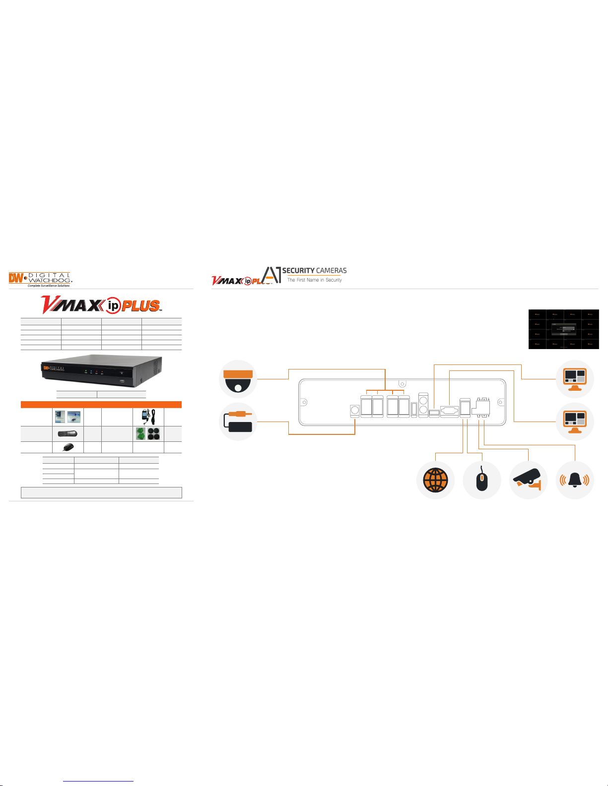
Step 1 – CONNECTING THE NVR Step 2 – POWERING UP THE NVR
SAFET Y TIPS
1. Mount and install al l necessary cameras an d external devices. Refer to their indiv idual manuals for
additional information.
2. Place the NVR in its nal position. See ins tallation tips below.
3. Connect all necessary cables to the NVR
4. Once all additional devices have b een properly connected to the NV R, connect the NVR to
an appropriate power s upply. The NVR will boot up automaticall y.
1. When the NVR boots u p, it will be in protective mode. This
means you will not be abl e to access the NVR’s setup menu
until you enter the proper u sername and password.
2. To unlock the NVR, right-clic k anywhere on the screen. The
login screen will ap pear. (Default Username / Password:
admin / no password)
3. When the NVR boots up for the rst time, you will b e guided
through the Startup Wizard.
1.
Make sure the cameras and t he monitors are properly conn ected to the NVR.
2. The NVR should be placed in a dust and m oisture free environment. It must neve r be directly exposed to
sunlight. Server ro om temperature is highly recomme nded to reduce the chance of overhe ating, which
may cause the NVR to bec ome unstable.
3. During the boot up process, the NVR sh ould not be interrupted by pressing any b uttons on the mouse.
Do not unplug the power a dapter or turn the NVR off duri ng the boot up process.
4. A UPS (Uninterrupted Power Supply) is hig hly recommended to prevent damage to th e NVR during a
power outage.
DC 48V PoE2
PoE1
PoE4
PoE3
PoE6
PoE5
PoE8
PoE7
AUDIO OUT
TV OUT
eSATA USB
LAN
PAL
RS485 SENSOR IN
RS485 SENSOR IN
ALARM OUT+
ALARM OUT-
NTSC
TV-OUT VGA
HD OUT VGA OUT
ADAPTER
CAMERA
VGA MONITOR
NETWORK CABLE USB MOUSE PTZ CAMERA ALARM / SENSOR
HD MONITOR
Back Panel Por ts may dier ac cording to mode l
Available from A1 Security Cameras
www.a1securitycameras.com email: sales@a1securitycameras.com
Page 2
Step 4 – MONITOR YOUR SYSTEM
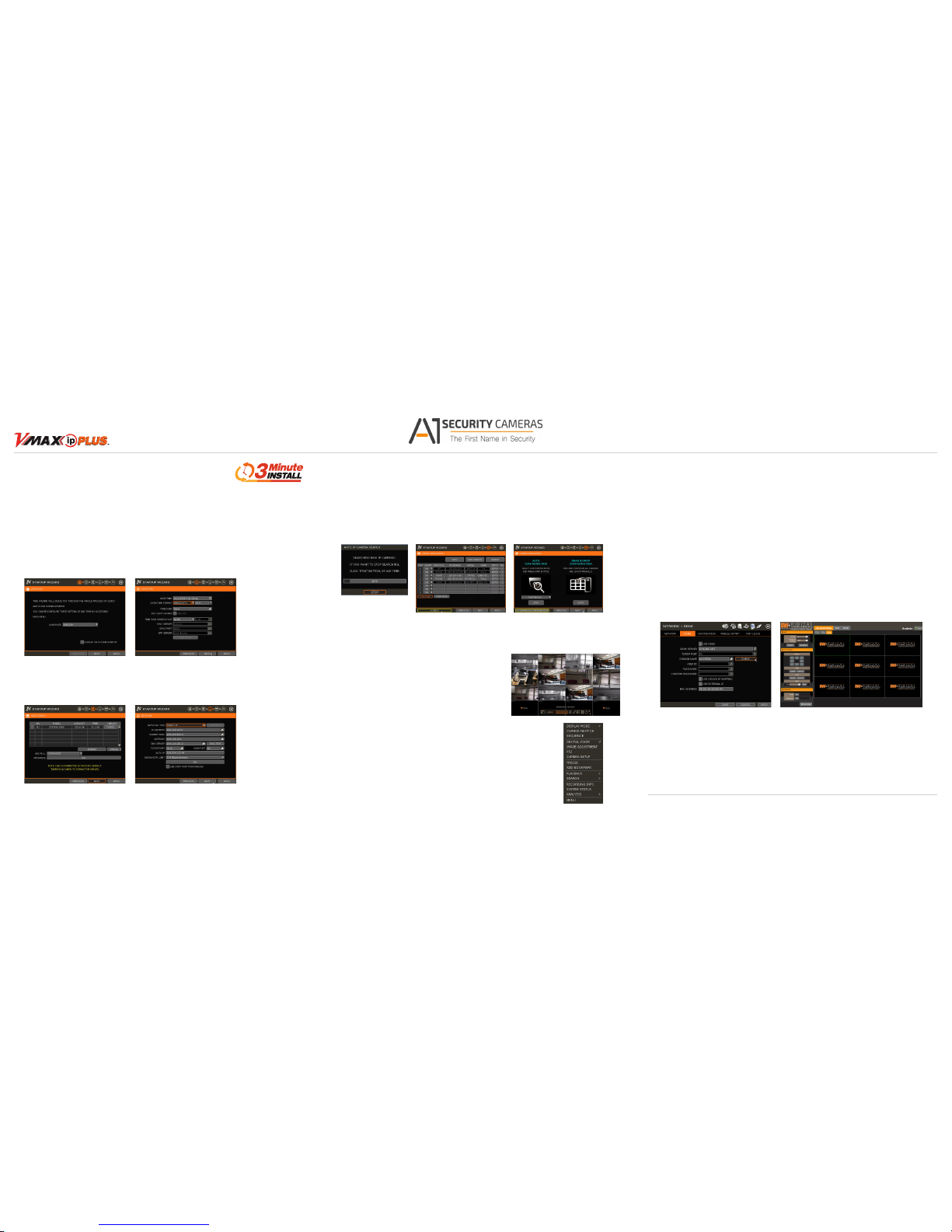
4. Set the NVR’s network settings to match yo ur network’s requirements. It is rec ommended to set the
network typ e to DHCP and let the NVR auto-detect the net work’s settings, then change t he type to Static.
Please contact your Net work Administrator for addition al information. Press Apply to Save and Nex t to
move to the next step.
5. The VMAX IP Plus’ Camera Con guration screen allows you to detect all the c ameras in your network and
automatically add th em to the NVR. Select one of the following o ptions:
a. AUTO MANAGEME NT – The system will automatically sc an the network and add the rst c ameras
it detects to the NVR. Camer as connected directly to the NVR’s PoE Switc h will be assigned to
channels automatically.
b. DRAG & DROP CONF IGURATION – The NVR will scan the net work for all supported cam eras and
display them in a table. Sel ect which cameras to add by click and ho ld the camera’s name, and
dragging it to the display a rea to its corresponding chann el.
1.
NAVIGATION – use the included USB m ouse to navigate around the NVR’s monitor ing and Setup pages.
a. To access the MENU BA R – move the mouse’s cursor to
the bottom of the display a rea to show the menu bar. You
can also display it con stantly by pressing the pin icon on
the right side.
b. To access the QUICK MENU O PTIONS – Right-click
anywhere on th e screen. This will take you to the quick
menu options, which in clude:
• Display Mode Options
• Camera Control features su ch as Digital Zoom, Virtual
PTZ and Camera I mage Adjustment and Setup
• Bookmark video
• Instant Playback and Se arch
• Recording and PoE status a nd analysis such as
network and system monitoring
• Access to the Main Menu
2. HELP – For your convenience, the HELP but ton located at the bottom right of
setup screens includ es basic information and explana tion of the features and
settings in that pag e, for on-the-go information.
Quick Start Guide
Rev Date: 12/15 © 2015 Digital Watch dog. All right s reser ved.
Step 5 – REMOTE MONITORING
DDNS Setup
The DDNS address prov ides your NVR a URL address, easier to rem ember than an IP address.
This is a free feature sup ported by Digital Watchdog for its custom ers.
1. Go to the Network setu p menu, and select the ‘DDNS’ tab.
2. Check USE D DNS to enable. (Make sure the NVR’s web por t has been properly setup in your ro uter).
3. Select DYNL INK.NET (default).
4. Enter a name for yo ur NVR and click the CHECK but ton. If the name is available, the system will
display the following me ssage: “THIS NVR NAME CAN BE USED”. Click SAVE to save all cha nges.
5. To use your DDNS, open a n Internet Explorer page and ente r the DDNS in the address bar:
NVRname.dynlink.net:port-number. (example: http://vmaxipplus.dynlink.net:80)
Step 3 – STARTUP WIZARD
1. Follow the start up wizard’s instructions to setup the NV R’s basic settings, including lang uage, date/ time,
network and con gure your cameras. At any time you can sk ip steps, go back, or exit the wizard and
setup the NVR manu ally.
2. La nguage – Select the appropriate la nguage from the drop-down menu o ptions. Press Apply to Save and
Next to move to the next step.
3. Set t he NVR’s date and time, including time zone, Daylig ht Savings and NTP Time Sync. If n eeded, set
the NVR to sync its time a utomatically with an externa l NTP server. Select the server fro m the TIME SYNC
MODE/CYCLE drop-down opt ions and the sync interval. Press Ap ply to Save and Next to move to the
next s tep.
Available from A1 Security Cameras
www.a1securitycameras.com email: sales@a1securitycameras.com
 Loading...