

Digital Watchdog DW-VAONE 43T, DW-VAONE 48T, DW-VAONE 44T, DW-VAONE 46T, DW-VAONE 81T User Manual
...Page 1

Rev: 0117
Page 2
User’s Manual | 2
Safety Information
The safety information is provided for the wellness of the equipment and for the safety of the
operator.
Please review and observe all instructions and warnings in this manual.
Note : Keep this manual handy every time you operate this equipment. Also, check with your dealer
for further assistance and for the latest revision of this manual. Your dealer might provide you with a
digital version of this manual. We also ask to keep the original box and packing materials in case of
return and for long-term storage of the DVR unit.
Preparations before installation
To protect your DVR from damage and to optimize performan ce, be su re to keep the DVR away from du st, humid ity, and
area with high voltage equipment such as refrigerator.
Do not install or place equipment in areas where the air vents can be obstructed, such a s in tight enclo sures or sm all utility
closet. Keeping the unit in a temperature-controlled room with ample regulated power is highly recommended. Do not
overload the wall outlet, as this can result in the r isk of fire or electric sho ck.
Uninterruptible power devices such as U PS power sur ge protectors are recom mended, and the DVR units must at least be
connected with UL, CUL, or CSA approved power surge protector. Avoid direct sun light and avoid heat.
FCC Information
This equipment has been tested and found to comp ly with the lim its of Cla ss A dig ital device,
pursuant to part 15 of the FCC Rules. These limits a re designed to pro vide reasonable protectio n
against harmful interference when the equipment is operated in a commercia l environment. This
equipment generates, uses, and radiates radio frequency energy, and if not insta lled and used in
Operation of this equipment in a residential area is likely to cause harmful in terference in w hich case t he user will be required
to correct the interference at his own expense. Changes or modifications not expressly approved by the party responsible
for compliance could void the user's authority to operate the equipment under FCC rules.
accordance with the instruction manual, may cause harmful inter ference to rad io communicat ions.
UL Information
- for pluggable equipment, the socket-outlet shall be installed near the equip ment and sh all be ea sily accessible
- if the battery is placed elsewhere in the e quipment, th ere shall be a marking close to the b attery or statemen t in the servicin g
instructions.
CAUTION
RISK OF EXPLOSION IF AN INCORRECT TYPE REPLACES BATTERY.
DISPOSE OF USED BATTERIES ACCORDING TO THE INSTRUCTION.
THIS EQUIPMENT IS FOR INDOOR USE, AND ALL THE COMMUNICATION WIRING IS LIMITED TO
INSIDE OF THE BUILDING, OR ANY SIMILAR WORD.
Page 3

3 | Full HD Digital Video Recorder
Contents
CHAPTER 1 : DVR USER MANUAL
1 GETTING STARTED 6
1.1 Checking Supplied Items 6
1.2 Connecting Peripheral Device 7
1.3 System Startup and Shutdown 9
2 EXPLANATION FOR EACH FUNCTION 11
2.1 Front Panel 11
2.2 Rear Panel 12
2.3 IR Remote controllerl 14
3 OPERATION 15
3.1 User Log-in 15
3.2 Quick Startup Wizard 16
3.3 Live Display Mode 17
3.4 PTZ Operation 22
3.5 Spot out Monitor 23
3.6 Playback of Recorded Video 24
3.7 Quick Backup during Playback 26
3.8 Search Recording Image 27
3.9 DST Setting 30
3.10 Schedule Reboot 31
3.11 Screen Saver 32
4 SETTING 33
4.1 System 34
4.2 Device 40
4.3 Record 47
4.4 Network 50
4.5 Export 57
4.6 Quick Setup 58
5 WEB SURVEILLANCE 59
5.1 Web Login 59
5.2 Web Configuration 60
5.3 Web monitoring 62
5.4 Web Playback 65
Page 4

User’s Manual | 4
APPENDIX : NETWORK SETUP FOR EXTERNAL USAGE 65
APPENDIX : SPECIFICATION 67
Page 5

5 | Full HD Digital Video Recorder
DVR U
Chapter 1
SER MANUAL
Page 6
User’s Manual | 6
1
G
ETTING STARTED
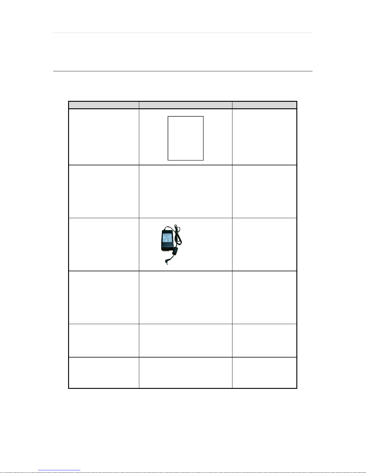
1.1 Checking Supplied Items
Make sure that you have the following items supp lied with y our DVR. If any of these item s are missing or da maged, not ify
your vendor immediately. Keep the packing utilities for moving or storage purpo ses afterw ards.
Items Photo Quantity
Quick Start Guide
12V DC Adaptor
Power Cable
(4- channel models)
12V DC Adaptor
Power Cable
(8- and 16- channel models)
Remote control
(Optional)
USB Mouse
Screws
1 Set
1 Set
1 Set
1 pcs
1 Set
1 Set
Page 7

7 | Full HD Digital Video Recorder
1.2 Connecting Peripheral Device
This section describes how to connect periphera l devices ef ficient ly to th e DVR.
Install the DVR on flat surface. If required, attach a ru bber mount for installat ion. If a 19-in ch rack is used w ith 1.5U Height
case, it is recommend to install the sy stem on a sh elf and use 2.5~3U (1U=1.75 inch or 4. 45 cm) space for proper ventilat ion.
NOTE
4ch 1HDD type
8ch 1HDD type
Install the system in a location with good ventilation to prevent overheating.
Page 8

16ch 1HDD type
User’s Manual | 8
16ch 2HDD type
WARNING !
※When connecting power cord to the system, it is strongly recommended first to plug the power cord
to the system and then plug the other side of power cord into the wall socket.
Page 9

9 | Full HD Digital Video Recorder
1.3 System Startup and Shutdown
1.3.1 System Startup
After connecting all necessary peripheral devices such as ca meras, mo nitors and a mouse to the DVR, po wer up the DVR b y
connecting DC12V adaptor to the p ower jack on the rear panel. The boot log screen wi ll appear. Please wait until the boo t
process is complete.
To login, right-click anywhere on the screen. Th is will bring up the login screen, where y ou can enter th e username and
password. There is only one Administrator Accoun t config urable in t he DVR sy stem. It is assigned w ith an unchan geable
User ID marked as ‘admin’. The def ault passw ord is e mpty (No Password). Administrator account has full a ccess to the DVR
and its configurable parameters. The Administrator Accoun t also has t he ability to cr eate n ew users and to assign right s to the
new user accounts. Those new users create d by the Administrator can also login with a specific password set by the
Administrator.
N
N
Do not forget the administrator’s password that was set for the first time. In case the password is lost,
OTE
contact your vendor.
The mouse is included. In case you need to replace it, it is highly recommended to choose well-known
OTE
major brands such as DELL, MICROSOFT, LOGITECH, or SAMSUNG.
Page 10

User’s Manual | 10
1.3.2 System shutdown and change password
To power off the DVR, follow one of the opt ions below :
1. Right-click on the screen and select ‘Shutdown’ from the drop-down menu. Enter the username an d password to power
off the DVR.
2. Right-click on the screen and select ‘Setup Menu’. Go to the System Settings sub- menu a nd select the ‘Def ault’ tab.
Press the ‘Shut Down’ button at the bottom right of the window. Enter your username and passw ord and select OK to
power off the DVR.
N
N
It is not recommended to disconnect the power cable abruptly from the back of the DVR because it may
OTE
affect the DVR and Hard Drive.
The default password for ‘admin’ account is no ne. Therefore, just click ‘Enter’ button on the d ial pad. If y ou changed the
password for ‘admin’ account, p lease ty pe in the cha nged password to login.
User can type in the password using the virtual keyboard or the numeric buttons on the IR remote
OTE
controller.
Page 11

11 | Full HD Digital Video Recorder
2 E
XPLANATION FOR EACH FUNCTION
2.1 Front Panel
4/8/16ch 1HDD type
16ch 2HDD type
No. Items Functions
1 LED Indicator
System status LED indicators
Green = The system is powered and ON.
Red = The system is currently recording
Yellow = The system is being accessed remotely via the network
2 USB Port USB Port for Mouse Operation, Backup Device or Firmware Update
Page 12

2.2 Rear Panel
4ch 1HDD type
8ch 1HDD type
User’s Manual | 12
16ch 1HDD type
Page 13

13 | Full HD Digital Video Recorder
16ch 2HDD type
No. Name Description
1 Video-In Camera inputs (Supports NTSC/PAL)
2 Audio-In Audio Input Device (with Amplifier)
3 Audio-Out Audio Output Device (with Amplifier)
4 USB Port USB 2.0 Port for Mouse Operation, Backup Device, or Firmware Update
5 HD OUTPUT HD OUTPUT
6 LAN Port
7 Power Input
8 Alarm Output Alarm Output
9 Sensor Input Sensor Input
10 RS-485 Port PTZ Dome Camera or External Keyboard Controller connection
VGA D-sub VGA Output
11
SPOT SPOT Output
12
Loop Loop Output
13
Note
Carefully check whether the specifications of the peripheral devices match the DVR’s specifications.
1 x 10/100/1000M
1HDD Type 4ch : 12V/2A 8ch : 12V/3A 16ch : 12V/5A
2HDD Type 16ch : 12V/5A
Page 14

2.3 IR Remote Controller(Optional)
The VMAX A1 DVR com es with a complimentary IR remote controller
User’s Manual | 14
The function buttons of the IR Remote Controller are a s below.
No. Functions
1 Start Instant Emergency Record
2 Numeric Buttons
3 Auto-Sequence on Live Display Mode
4 Spot out monitor
5 Channel Selection
6 Instant Playback
7 Search Button
8 OK (Select) Button
9 Audio Mute
Playback Control on Search Mode
10
(Fast Backward/Pl ayback/Stop/Fast Forward)
11 Exit Menu Setup
12 Display Mode
13 Digital Zoom
14 Bookmark
Zoom In & Out Button
15
16 Backup
17 PTZ Control
18 Directional Arrows Buttons (Up/Down/Right/Left)
19 Menu Setup
Page 15

15 | Full HD Digital Video Recorder
3 O
PERATION
3.1 User Log-in
The DVR has various setting categories. The administrator can set the syst em password and <U ser> to prevent
unauthorized changes to setting values and alteration of recorded f ile.
Enter the <Admin> or <User> password which had been set by using t he virtual keyboar d.
N
1) <LOGIN> window will be displayed until user logs in with the right ID and password.
OTE
2) If the DVR is set to Auto Log-In, DVR does not require LOG-IN. (Please refer to 4.1.2 User.)
Page 16

User’s Manual | 16
3.2 Quick Startup Wizard
Quick Startup Wizard is specially designed to make it much ea sier for th e major DVR sett ings such a s Time/Date setup,
Record setup, Network setup and Quick setup. When the DVR boots up, the Quick Startup Wizard oper ates automa tically. It
can be disabled by setting in the main menu.
Adjust the date & time for the DVR.
Setting this before the DVR starts
recording will prevent and time
conflict, which may result in data loss.
See section 4.1.1 System Info for
more information.
See section 4.4 Network for more
information on setting up the DVR for
external connection.
Use the DVR recording calculator to
setup the best recording parameters
for your needs. See section 4.6 Quick
Setup for more information.
Page 17

17 | Full HD Digital Video Recorder
3.3 Live Display Mode
3.3.1 Full HD(1080p) Live Display
Full HD Live Display can be supported in live mode by using its HD output.
Able to set max 4k(3840x2160) : HD output and supplied 4K monitor
N
HD Resolution 4K(3840x2160) support only 8ch and 16ch. 4ch is not support 4K resolution.
OTE
<Full HD Live Display>
Page 18

User’s Manual | 18
3.3.2 Channel Selection
Channel selection can be done by following one o f the st eps below:
1. CH1~CH16 buttons in the IR Remote Control.
2. 1~16 virtual buttons at the bottom of the GUI d isplay.
The display mode can be changed by select ing the appropria te disp lay mode from the m enu bar at the bo ttom of the display
area.
The live images can be displayed in real-time in 1 , 4, 9, 16 screen split s (depending on the mode l and the supported
channels). Whenever the left/right arrow button on the front panel or IR remote con troller is pressed, the screen w ill be
sequentially changed.
[1 Ch] [4 Ch]
[9 Ch] [16 Ch]
To select channel by mouse, click target channel single time to display in full screen . To return to previous display mode,
click the screen again.
To view the pop-up menu, right-click anywhere on the display screen.
NOTE
To select a channel using the mouse, perform a slow and clear click of the left mouse button.
Page 19

19 | Full HD Digital Video Recorder
3.3.3 Icons
The live mode display’s icons or messages w ill be ind icated on the screen to indicate the sy stem mode or statu s.
Below are the icon categories that are indica ted on t he monitor:
at Left-upper corner on each channel screen
NOTE
To show the menu bar , move the mouse’ s cursor
to the bottom of the screen. The menu bar wi ll be
displayed.
To hide the menu bar , move the mo use’ s cur sor
away from the menu bar .
Right-click the USB mouse to access the pop up
menu.
Icon to be shown
Continuous Recording
Motion Detection Recording
Sensor Activating Recording
Continuous+ Motion Recording
Continuous + Sensor Activating
Recording
Emergency Recording
If you cannot find any colored-mark in the top right corner of the live screen mode, then the system is not
set to record any image. Check the recording schedule or camera in the main setup menu.
at Left-bottom corner on full screen.
Icon to be shown
Sequence display on
Digital zoom on
Audio Channel
Menu Bar
Menu button. When pressed, System Setup, Search, Backup, Logout will appear.
Screen split options- Select from single channel, 4 channel, 9 channe l, or 16 channel display.
Sequence- if pressed, the system will start displaying all the channels in sequence mode.
To stop, press the button again, or right click on the screen and select ‘SEQUENCE’
CH. Buttons- view a specifc channel in full screen mode.
Instant (emergency) recording- The system will record video based on the panic record
settings.
PTZ mode- Control any supported PTZ cameras by moving the mouse pointer.
Go to Instant playback.
HDD usage indicator- Indicates the percentage of your HDD being used. If it shows 60%,
then 60% of HDD space has been used.
Page 20

User’s Manual | 20
3.3.4 Pop-up Menu
Right clicking anywhere on the screen will open up the pop up sub-menu as shown below.
DISPLAY- Select the display split from the available options:
- 1 Screen- Single channel. Automatically display s CH1. If 1 Screen is sele cted aga in, next chr onolog ical channel will b e
displayed.
- 4 Screen- Quad mode. Automatica lly di splay s channels 1 ~4. If 4 Scree n is se lected aga in, the next chron ological 4
channels (5~8) will be displayed.
- 9 Screen- Automa tically display es channels 1~9 . If 9 Screen is se lected again, the next cohoro nological channels
(10~16+1~2) will be displayed.
- 16 Screen- Displays all 16 channels (available only in 16 channe l models)
PTZ CONTROL- Open the DVR’s PTZ control. See sect ion 3.4PTZ fo r more infor mation.
SEQUENCE On/Off- when selected, icon will appear on the bottom right corner of the screen, and the display
screen will be sequentially changed.
Please note, option will be disabled if disp lay area is in Max channel mo de.
Spot out Monitor- Enter Spot out Monitor Control Mode.
ZOOM- Enables/ disables digital zoom function with x 2, x4, x8 button. When enabled, icon will appear and
zoomed area will be displayed on the bottom r ight corner. The Zoom will automa tically focus on the center of the ca mera’ s
display . To adjust it, go to the small zoom display at the bottom of the camera d isplay and move the y ellow fr ame to the area
you would like to view. To move the yellow frame, use your mouse to drag the lines to the desired location. To go back to live
display mode, right-click on the screen and select “ZOO M” again. This feature is available in single channel mode only.
INSTA NT REC On/Off- Start/ Sto p Panic Recording.
PLAYBACK- Select playback option:
- 10, 15, 30, 60 seconds- start playback from the selected number of seconds ago.
- 2, 3, 5, minutes- start playback from the selected number of minutes ago.
- Open Playback Mode- automatically go to instant playback.
SEARCH- Select video search options:
- Date/ Time- open calendar search.
- First/ Last Data- Go to the first or last recorded data.
- System/ Event Log- open log search window.
- Bookmarks- open bookmark search.
EXPORT - Users can archive a video clip recorded for a certain period o n a selected channel.
SETUP- open the DVR’s main menu.
SHUT DOWN- Power off the DVR.
LOGOUT- User logout.
Page 21

21 | Full HD Digital Video Recorder
As the Admin u ser, you can seup up multiple users with dif ferent le vels of auth orization. I f a certain u ser is not a llowed to view
a certain camera in live or playback, then no image will ap pear on the d isplay screen. To create, delete, or modify users, go to
the main menu and select system settings. S ee sect ion 4.1.2 U ser for more inform ation.
Page 22

User’s Manual | 22
3.4 PTZ Operation
Before starting PTZ control, please make sure the ca mera you w ish to contro l is a su pported PTZ cam era and is in stalled an d
configured properly. See section 4.2.6 PTZ for setup information. To enter PTZ mode, follow one of the options below:
1. Right-click on the screen and select PTZ Control.
2. Click on the joystick button in the menu bar located on the bottom of the main screen.
3. Press the PTZ button on the IR remote control.
4. Also to use UTC click the button, the camera menu display on the full screen. And user move button menu
by up/down, left/right button change the setting. Enter is select menu.
In PTZ mode, user can control PTZ operation with the USB mouse.
While pressing the left button of the mouse, drag t he mouse po inter up/dow n, left/r ight to move pan/tilt po sition of t he camera
accordingly . The further aw ay from t he center of t he screen y ou move t he mouse, faster w ill the ca mera move.
NOTE
For focus control in PTZ mode, right-click to get the pop-up men u as show n below. Default mode is to “ZOOM”.
The user can also select the preset button to star t/ stop a pre set, or exit PTZ screen model.
NOTE
Full PTZ functions are available by using USB mouse, IR remote control, or keyboard controller and are
available only on supported PTZ cameras.
User will see numeric pad to select “Preset” number. The preset is defined by setting a PTZ protocol in
the setting menu. The maximum number of preset is 255, but the number of available presets may vary
by camera make and model.
Page 23
23 | Full HD Digital Video Recorder
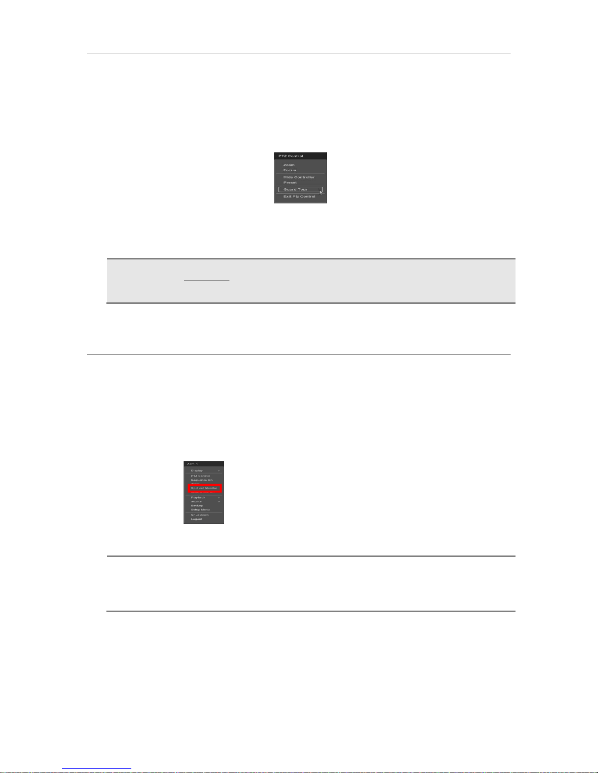
User can automatically switch PTZ camera positions according to defined presets by using the GUARD T OUR fun ction. The
connected PTZ camera must support touring functions. “GUAR D T OUR” on the pop- up menu can be enabled only in fu ll
screen mode. See 4.2.6 PTZ for instructions on how to setup the GU ARD TOUR.
CAUTION
Depending on PTZ camera, some preset positions might be skipped if, for example, the PTZ camera
cannot mechanically move or control focus within the interval time required by the DVR. In this case,
it is recommended to increase the interval setting to a value that allows for the cameras to finish its
Pan & Tilt.
3.5 Spot out Monitor
Click the right button on the mouse and select the Spot out MONITOR in order to enter call monitor contro l mode. The
numeric panel will pop up at the center of the screen .
Click the specific channel button on the numeric panel to display fu ll screen mod e out of a ssigned spot out channels.
▪ Press the close button on the bottom of the numeric pane l. It will go b ack to the previo usly programmed spot monitor mo de.
NOTE
- A spot out monitor displays another spot out monitor’s video in full screen through the function, spot out
monitor.
- In spot sequence setting mode, if spot out monitor is selected, spot sequence stops and selected
channel pops up.
- While call monitor runs, if a channel event happens, spot out monitor stops and the event pops up.
Page 24

User’s Manual | 24
3.6 Playback of Recorded Video
To play a recorded video, press the Play button fr om the menu bar, or the Instant Play in t he IR remote co ntroller.
The recorded files can be seen in rewind or fast forward modes. Press the rewind a nd fast-forward butto ns to contro l the
playback’s speed (x 2, x4, x8, x16, x32 real time).
User can click playback to automatically play the latest video clip in rew ind mode.
In playback screen, user can make various play back modes, make an instant manua l backup (ar chive), go to calendar
search mode, change channel, and chang e screen m odes. By clicking t he left mouse b utton in the colored-time bar, the user
can jump to a different time in the r ecording . In addit ion, user can mo ve the vertica l search b ar and release by dragging it
back and forth to search the desired time in deta il.
Page 25

25 | Full HD Digital Video Recorder
Button Function
N
OTE
Jump to first data. If recording i s set to motio n, system will jump to pr evio us recorde d motio n video.
Fast rewind
Frame-by-Frame Rewind
Play video in rewind
Pause video
Exit Playback to Live mode.
Playback video
Frame-by Frame playback
Fast playback
Jump to last data. If recording i s set to motion, system will ju mp to th e next recor ded moti on video .
Go to calendar search
Bookmark Video
Backup
Exit Playback to Live mode.
During playback, the DVR supports the following playback speed:
30fps in single channel view.
15fps in multi-channel view.
Page 26

User’s Manual | 26
3.7 Quick Backup during Playback
User can easily archive video while viewing the vid eo playback. See sect ion 4.5 Export for more inf ormatio n on manual
backup from the setup menu.
1. In live mode, right-click anywhere on the screen and select ‘Ba ckup’ to open the backup menu.
2. In playback mode, press the ‘Backup’ button on the popup me nu bar to open the backup menu.
3. Adjust the following options:
a. Select the channels to be included in the backup file.
b. Adjust the start and end time of the backup file.
c. Select to include the Backup Viewer with the archived file.
d. Press the ‘Calculate’ button to see the expected size of the ba ckup file.
e. Press the ‘Scan’ button next to the device to find the U SB drive for ba ckup.
f. Edit the file name and add a pro tection pa ssword if needed.
g. Press ‘Start’ to start the
backup process. A progress
bar will appear on the screen.
N
OTE
instructions on how to correctly setup main functions in the DVR.
The “HELP” button offers interactive help, recommended settings and step-by-step
Page 27
27 | Full HD Digital Video Recorder
3.8 Search Recording Image
3.8.1 Date/Time Search
To search your recorded data by date/ tim e, follow on e of the opt ions below :
1. Click the quick Menu button at the left side of the menu bar, select Search Date/ Time
2. Right-click anywhere on the screen, select Sear ch Date/ Time
The calendar window will appear, Days with recorded data available w ill be indicated in RED.
1. Select from the calendar the date.
If necessary , use t he manual y ear
and month options on the left side
to adjust the calendar view.
2. The ‘Intelli-Search Bar’ at the
bottom of the window will display
hours when recorde data is
availablein color code. Once the
recorded video data of the
selected date is shown, user can
adjust the vertical search line to
the time that user wants to search
by dragging a mouse. As the
vertical line is moving back and
forth, user can see “the Search
time” clock is also changing.
When user decides the Search
time, click Play to see the
selected video data.
4
1
3
2
5
3. The recording mode will be distinguished in the time bar according to color:
Color Recording Mode
No Color Camera has no recorded data for the selected t ime.
Red Panic recording triggered by the user.
Yellow Continuous recording.
Green The system records o nly w hen motion is detected
Blue “Continuous” + “Motion”-The system records continuously and will switch to motion record ing configurat ion
Orange The sy stem records when a sensor is triggered an d only during the dwell time as se t in “ SENSOR” of the
Brown “Continuous” + “Sensor”- The system records continu ously and w ill switch sensor record ing if a sensor is
if motion is detected. The sy stem will a lso send a “mot ion event” m essage to the Pivot Client Softw are. If
“MOTION ALARM” is disabled in the “DEVIC E” menu, and record ing is set to “CONT + MOT”, the system
will record with continuous record ing even w hen motion is detected in motion area.
“DEVICE” menu. If “SENSOR” is disabled under the “DEVICE” menu, a nd recording schedule is set to
“SENSOR”, the system will not record even though a sensor is tr iggered.
triggered during dwell time. Th e system w ill also se nd a “sensor e vent” message to the Pivot C lient
Software over the network. If “SENSOR” is disabled in the “DEVIC E” menu, and re cording mode is set to
“CONT + SENS”, the system will record w ith continuous re cording even when a se nsor is triggered.
Page 28

User’s Manual | 28
C
AUTION
4. To view video from the selected time, fo llow one of th e option s below:
5. Press the ‘Play’ button at t he botto m fo the wind ow. The system will d isplay all channels in playback m ode,
Dark Blue Color
The data recorded during DST (Daylight Saving Time) will be indicated in Dark Blue color in the IntelliSearch Bar on playback mode.
a. Use the manual hour option to view specific hours of the day.
b. Using the table, click on the hour you would like to vie w in play back.
corresponding to the selected date and time .
3.8.2 Event Log
The Event log search allows you to search f or a part icular event, displaying the sear ch results in a detailed table .
1. To open Event Log Search, perform one o f the follow ing option s:
a. Click quick menu butt on, select Search Event Log
b. Right-click anywhere on the screen ans select Search Event Log.
2. Select the date you would like to se arch.
3. Select which events to include in the report. Select from Sensor, Motion, Video Loss, P anic Recording , HDD Full, or All
4. Press ‘Search’. The system will d isplay all search re sults in the table, st arting with the latest even ts.
5. Use the buttons on the bottom of the window
to switch between the report’s pa ges.
6. Export the log report to a USB memory
device in text file format.
a. Attach a USB memory stick to the
USB port
b. Press “SCAN” to detect the USB
stick
c. Press “EXPORT” to copy the log
information to the media.
7. Click play icon to play back the
selected event data.
N
If an alarm or event do not appear in the envent log, check the alarm settings, and connection port at the
OTE
DVR’s rear panel.
Page 29

29 | Full HD Digital Video Recorder
3.8.3 System Log
The system log search allows you to search for any changes made to the sy stem, di splay ing the search re sults in a deta iled
table.
1. To open System Log Search, perform one of t he follow ing options:
a. Click quick menu butt on, select Search Sy stem Log
b. Right-click anywhere on the screen ans select Search System Log .
2. Select the date you would like to se arch.
3. Select which events should be inclu ded in the log report. Sele ct from: S ystem, Setup, Network, or All
4. Press ‘Search’. The system will d isplay all search re sults in the table, st arting with the latest even ts.
5. Export the log report to a USB memory
device in text file format.
a. Attach a USB memory stick to
the USB port.
b. Press “SCAN” to detect the
USB stick.
c. Press “EXPORT” to copy the
log information to the media.
3.8.4 First Data
Go to the first screen of the recorded video. Th is is the oldest video recorded.
3.8.5 Last Data
Go to the last screen of the recorded video. Th is is the latest vide o recor ded.
3.8.6 Bookmark
Go to the bookmark list to search recorded video in th e bookmark list. Users can m ake their ow n bookmark list by clicking th e
button during playback. The first ‘Bookmark’ press w ill indicate t he start time f or the boo kmarked video. Press the
button again to end the bookmark and save it. Click the button next to any bookmark event to playback
video.
Page 30

User’s Manual | 30
3.9 DST Setting
DST starts at 2:00AM local time on 2nd Sunday of March, and ends at 2:00AM DST on 1 st Sunday of No vember.
During DST (Daylight Saving Time), the DVR’s clock needs to be adjust ed accordin g to re gional time zone. The DVR’ s t ime
will shift one hour after the DST sett ings star t, and the DVR will rest ore the t ime clock ba ck to normal after DST en ds.
To enable DST setting on the DVR, right- click any where on the scre en and go to: SYSTEM > SYSTEM INF O and click
“DATE/TIME” to get the DST sett ing window. Check the box next to “USE DST” and se lect the DST “Begin & End” time.
Since the clock jumps from 2:00 to 3:00, when you go to search mode, you can see there is no dat a in al l channels for one
hour due to DST.
When DST ends, there is an hour of overlapped video. The overlapped video will be indicated in a dark b lue color on the
Intelli-Search Bar during playback mode.
Page 31

31 | Full HD Digital Video Recorder
When user click the overlapped period, “Recorded video Se lect ion” message will pop up. Select whether to play DST data or
Non-DST data.
.
Click OK to play DST image. Click CANCEL to play Non-DST image.
[“DST” image is displayed on screen] [“Non-DST” image is displayed on screen]
3.10 Schedule Reboot
Add Schedule Reboot
Reboot the DVR on a designated date and time. During the long time working, refresh the DVR automatically
Click the Schedule Reboot button>Check the 'USE' >Select week>Select day.
Page 32

User’s Manual | 32
3.11 Screen Saver
The Screen Saver features protects the screen an d data of the DVR by turning of f after a set t ime of ina ctivity. To enable the
Screen Saver, r ight-click anyw here on the screen and go to the menu setup: SY STEM > SY STEM INFO and click “SCRE EN
SAVER”. Select H D output and set the W a iting Time from the options in the drop- down me nu.
NOTE
The Screen Saver will not work if Waiting Time is set to “NONE” or the HD output box is unchecked.
Screen Saver may also be disabled during a firmware upgrade, HDD format, or data backup. The system
will continue to record while the monitor is off.
Page 33

33 | Full HD Digital Video Recorder
4 SETTING
General settings structure consists of “System”, “Device”, “Record”, “Network”, “Export,” and ‘Quick Set up”.
To open System Log Search, select one of the follow ing option s:
1. Click the button in the quick menu bar and select Setup Menu.
2. Right-click anywhere on the screen and select Setup Menu.
To view the sub-menu categories for each menu op tion, hover t he mouse over the menu option. To enter the setup menu,
click on the desired category.
<SYSTEM> <DEVICE> <RECORD>
<NETWORK> <EXPORT> <Q-SETUP>
Main Classification Sub Classification
SYSTEM
DEVICE
RECORD
NETWORK
EXPORT
Q.SETUP
SYSTEM INFO
USER
CONFIGURATION
HDD
FACTORY DEFAULT
REGISTER PRODUCT
CAMERA
AUDIO
SENSOR
MOTION ALARM
EXTRA ALARM
UTC/PTZ
RECORD SETUP
PANIC RECORD
SCHEDULE
HOLIDAY
NETWORK
DDNS
NOTIFICATION
HEALTH CHECK
PATH FINDER
EXPORT
QUICK SETUP
Page 34

User’s Manual | 34
4.1 System
4.1.1 System Info
The System Info sub-menu includes the following options: Date/ Time, HD output Resolution, Language, R emote ID, Version
& System Upgrade, Video Signal, IP & MAC Addre sses, Keyboard Set up, NTP Setup, D isplay Setup, and Screen Saver
Setup.
- Date/ Time- Using the available options, manually
adjust the date and time, select the display mode for the
time and the date, and select the appropria te time zon e.
If applicable, check the ‘USE DST’ box. See 3.12 DST
Setting for more information.
- HD Resolution- Select the DVR’s output resolution.
DVRs support the following video resolution s:
1024x768, 1280x1024, 1920x1080, 3840x2160(4K no
support 4ch model.)
User must set the proper resolution according to the
monitor resolution
- Language- Select the DVR’s display language from the availanle in the drop-down menu .
- Remote ID- Set the DVR’s remote ID, which should be the same as th e IR Remote Cont rol (default ID is 1).
- Firmware Version & upgrade- when a new version is available use the easy upgrade menu to upgrade your DVR. It is
always recommended to maintain your DVR up to d ate with the latest firmw are to guarantee t he DVR’ s proper
functionality . To upgrade your system:
Upgrading system using USB memory stick:
1. Insert a USB drive with the firmware file formatted by FAT32 in any USB port of DVR (compatible with USB
2.0).
2. Select ‘USB’ from the Me thod drop down options and press the ‘Scan’ button.
3. Once the system detects the USB drive, it will d isplay the firmw are file under ‘Upgrade File Name’ and the
‘New Ver’.
4. Click “OK” to confirm.
Page 35

35 | Full HD Digital Video Recorder
- Upgrading system using Digital Watchdog’s FTP serv er:
1. Select FTP in the drop-down options under ‘Method’.
2. Enter the FTP’s address: ftp.dwcc.tv
NOTE
C
AUTION
- Video Signal- Displays the video input signal to the DVR. This is a default in formation an d will display NTSC or PAL,
depending on the signal from the cameras.
- IP & MAC Addresses- This information is necessary w hen connecting to the DVR via it s w eb viewer or the Pivot Client
Software. See section 4.4 Network for more information and setup.
- Keyboard setup- Setup the DVR’s ID, baudrate and model to match the informatio n of th e keyboard y ou would like to
use. The Keyboard’s ID must match the ID set in the DVR.
The FTP server address is subject to change without a prior notice
3. Enter the username and password (these should be filled out au tomatically ). Username: vmaxa1 passw ord:
vmaxa1
4. Click ‘Check’ to allow the DVR to connect to the FTP server and check the latest Fir mware ver sion. If a new
firmware is available, the DVR will ask you
whether you want to upgrade it or not.
5. Click ‘OK’ to confir m and click ‘STAR T’ to start
upgrading.
It is recommended to format the HDD after firmware upgrades because the data recorded by previous
firmware may cause malfunction of DVR.
It is highly recommended to check all functions and menus after a firmware upgrade for proper layout
and performance. If necessary, you can return system to its default settings.
- NTP Setup- Setup the DVR to automatically sync with a Network Time Protocol.
There are two types of TIME SYNC MODE:
o Client Mode- The operating DVR is set as the
client DVR. Enter the IP address or URL of a nother
DVR or Central Monitoring Software (CMS), as a
Time Sync Server in “ SYNC SER VER”. Thi s will
cause your DVR to sync its time w ith a Time Sync
Server in the set interval time.
- Display Options- Setup OSD information in live and
playback modes, transparency, spot output, sequence dwell
time, spot-out dwell time, and pop-up camera
Page 36

o OSD:
Select which information to display in the OSD on each channel in Liv e.
Select which information to display in the OSD on each channel in Playback.
o Set the OSD’s transparency le vel. The h igher the n umber, the more transparent the text will appe ar.
o Setup a dwell time for the OSD text, after which, the OSD w ill disappear.
o Setup a dwell time for the Setup Menu, after which, the Menu w ill disappear.
o Set sequence dwell time- Setup how long each channel w ill be display ed in Sequen ce mode, be fore
switching to the next view .
- Screen Saver Setup- See section 3.11 Screen Saver for more information.
User’s Manual | 36
Page 37

37 | Full HD Digital Video Recorder
4.1.2 User
Master user is always the Adm in with factory default o f No password. This u ser cannot be deleted. It is recommended to
change the Admin ’s pa ssword for ex tra security. The admin user can d esignate a n ew user w ith dif ferent per mission leve ls by
functions, menu access and live & playback.
To add a new user , go to the Sy stem Setup Menu, and select System > User.
To add a new user , pres s the ‘Add’ button.
To edit an existing user , pre ss the ‘Edit’ button.
To delete an existing user , check the box next to th e user and pre ss the ‘Delete’ button.
User Add/ Edit Screen:
- Authority/ User – enter the user’s name on the
right side. Use the pencil button to open the on
screen keyboard. Enter the password for the
username. This is the login password to the D VR.
- Function - restrict a user’s access to functions
such as search, PTZ control, backup, and
playback.
- Menu Access- restrict a user’s access the DVR’ s
system, device, record, network, backup, and
quick setup menu options.
- Live & Playback- restrict a user’s viewing of deselected channels. If a ch annel is deselecte d, user will not be able to
view live or playback for that certain camera chan nel.
N
To setup auto login for users, so the y do not ha ve to enter th eir password w hen logging to the DVR, pre ss the ‘Option s’
button. You can select to allow a u ser to auto login on DVR bo ot up, or setup an auto log out. If enab led, the DVR w ill
automatically log out of a user’s access after a set time of inactivity.
Total number of users including administrator is 9 users.
OTE
Page 38

User’s Manual | 38
4.1.3 Configuration
Copy the system configuration valu es from this D VR to sa ve for your record s or copy to another DVR. “ Export” allows y ou to
copy the settings to a USB memory device. “Import” allow s you to apply previously sa ved sett ings from a USB de vice and
override the current DVR settings. You can select to import or export specific settings, or copy the DVR’s entire se tup option s.
During import, make sure the firmware version of the sour ce DVR is the same as the de stination DVR.
4.1.4 HDD
HDD sub-menu displays all relevant information regarding all HDDs inst alled in t he DVR. Press ‘Check’ next to the HDD’s
name to view that HDD’s health sta tus. The sy stem wi ll display :
Model: Make and model of the Hard Drive.
Size: Total HDD size, in KB.
Temperature: HDD temperature. Normal operating temperature s is bet ween 30° and 45° C degrees.
Live Time: Remaining esti mated hours o f operation.
Bad Sector: any unusable areas in the HDD that may affe ct recording.
Select “Overwrite” or “Rec Stop” when HDD is full. If ‘Overw rite’ is selected, n ew vid eo will be recorded OVER older dat a
when HDD is full. If ‘Rec Stop’ is selected, a ll record ing will stop when t he HDD is full.
To format the HDD, check the box next to the HDD, and click “HDD C lear”
If system resources are occupied with ta sk, such as making a network con nection or per forming video play back during the
format process, the format may fail. If the format fails, reboot the sy stem and try aga in.
N
1) Formatting may take 40 sec for 320GB, 1 minutes for 500GB, or 7 minutes for 2TB.
OTE
2) The system always reserves a maximum of 20GB of space in each built-in HDD for archiving
effectively.
Page 39

39 | Full HD Digital Video Recorder
4.1.5 Factory Default
With an authorized password, you can reset the sy stem back to it s factory default con figuration. You can select which
configurations to reset to default, or select al l for an o verall fact ory reset. You can also chose to enable the Quick Startup
Wizard after reset. See sect ion 3.2 Quick Startup Wizard for more info rmation.
N
All the configuration values made by the user will be deleted. The system setting will be sent to factory
OTE
defaults. The recorded video data will not be erased.
4.1.6 Register Product
Registering your Digital Wat chdog product speeds up y our access t o our Technical Support personnel should you require
assistance.
N
Please enter all of the information required to set up your account
OTE
Page 40

User’s Manual | 40
4.2 Device
There are seven sub menus in the Device menu, including Camera, Audio, Sensor, Motion Alarm, Extra Alarm, and PTZ.
4.2.1 Camera
Users can setup the camera’s title, brightness, contrast, color, motion sensitivity, and audio mapping. The motion area
setup is the entire camera area. To disable motion detection for parts of the camera’s view, uncheck the corresponding
boxes, removing the yellow markers.
Audio mapping is Applies a user specified channel to audio connection.
Automatically detect the cameras such as 3M, TVI, HDA(Analog HD) and 960H. (Set Video Type as AUTO)
Most type of camera is automatically apply 3M, TVI, HDA, 960H
HD-TVI type : In case of TVI camera disconnect, Please set it manually
HD-A type : In case of HDA camera disconnect, Please set it manually
HD-CVI type : In case of CVI camera, please set ‘HD-CVI type’ manually
N
When Auto detection is not working well under improper environment,select type of camera directly on
OTE
Video Type.
Page 41

41 | Full HD Digital Video Recorder
- Event Camera Group Recording:
This feature allows users to setup a recording rule so when a sing le camera ha s an even t triggered, mu ltiple ca meras w ill
start recording. There are a total of four (4) groups you can setup (Group A~D). Each camera can be adde d to one group
only . The group’s recording parameters will fo llow that of t he first camer a added to the group. For example, if CH 4 was
added first to Group B, then all other cameras in Group B will fo llow CH4’ s recording settings for e vents.
To setup:
1. Go to the master channel, the one you want to use as the recording guide for all oth er cameras in the group.
2. Under the GROUP REC. drop-down, select the group you want to add the camera to (For example, GROUP A).
3. Go to the next camera you want to add to this group. Select the same group (GROUP A) from the GROUP REC. drop-
down.
4. Click SAVE. Repeat with all other cameras y ou want to add to that group .
Below is an example how Event Camera Group Recording w orks:
Recording Scenario #1 ( CH1,2 and 3 is GROUP A)
CH1- Motion Recording , CH2-Sensor Recording, CH3- Continuous Recording. CH2 & CH3 will follow CH1’ s (Master CH)
recording schedule.
When one of the camera detects motion, all 3 cameras in the group will start recording a s motion (CH1’ s settings).
NOTE
Setting up PANIC recording for a camera in a group will trigger panic recording for all channels of the
DVR.
If the master camera’s settings are set via the quick setup mode, all other cameras in the group will follow
the same quick setup mode schedule if an event is detected.
The Event Camera Group recordings work on Sensor and Motion detections only..
Page 42

User’s Manual | 42
4.2.2 Audio
Users can select the audio input and output dur ing live display and mat ch the audio input to a de signated channe l. (Ple ase
refer to Section 4.3.1 Camera Record).
In addition, users can listen to the audio for b oth live d isplay and play back mode through t he network using Central
Management System (CMS), web browser.
4.2.3 Sensor
Use the sensor setup menu to enable and assign sens or and alarm tr iggers to corresponding cameras. Sele ct the sensor
type, enable notifications for each sensor, assign relay action and set th e dwell time
Type- OFF, N/O (Normal Open) , N/C (Normal Close) The Sensor.
Cam- Select the associated camera for each sensor connected to the DVR.
Notify- Select how to alert when a sensor is activated or motion is triggered. The system can generate a buzzer
sound and/or have a pop-up screen for the camera.
C
AUTION
Relay contact can handle up to 24VDC/1A(or 125VAC/0.5A) of other devices. If connected to a circuit
that is over 24VDC/1A(or 125VAC/0.5A), the system may experience problems.
Page 43

43 | Full HD Digital Video Recorder
Preset- Assign apposit ion for t he camera to move to when a sensor is triggered. (Th is option requires a PTZ camera.
See section 4.2.6 PTZ for more information).
Relay- OFF/ON- enable or disable relay output when a sensor is activated.
Dwell Time- Set the recording period from the start of sensor a ctivation. During th is period, the correspondin g camera
will record according to the frame an d alarm (re lay) out put set. The record ing stops and alar m output is turned off
when the dwell time ends.
NOTE
NOTE
NOTE
“Sensor” refers to the alarm connected to the DVR, triggered by a physical sensor input.
If the sensor does not operate properly, check the setting of the sensor type (N/O or N/C).
The alarm might not function if the actual connecting sensor type and the sensor type in the system
setting are inconsistent.
“Camera pop-up” means that if the DVR Is displaying a multi-channel view, the view will switch to single
channel mode when an alarm is triggered.
Page 44

User’s Manual | 44
4.2.4 Motion Alarm
Select Motion alarm to record only w hen motion detect ion is tr iggered b y DVR S/W upon user’s defined motion area.
An alarm signal is sent via the selected sensor-out channel. To enable, check the box next to each channel, select the
notification option (beep and/ or camera popup), se lect to en able a rela y output w hen motion a larm is trigge red, and set the
dwell time for recording.
Notify- Select how to alert when a sensor is a ctivate d or motion is tr iggered. The syste m can generate a buzzer
sound and/or have a pop-up screen for the camera.
Relay- OFF/ON- enable or disable relay output when a sensor is activated.
Dwell Time- Set the recording period from the start of sensor act ivation. During th is period, the correspondin g camera
will record according to the frame an d alarm (re lay) out put set. The recording stops and alar m output is turned off
when the dwell time ends.
Copy Setting- you can copy the settings from one sensor inp ut to mult iple sen sors for ea sy and qu ick configuration.
Choose the sensor you want to copy from at the “From” fie ld. Choose the sett ings you want to copy by select ing the
check box next to each one. Check the checkbox next to the sensor numbers to apply the copy setting(s) to on the
“To” box.
N
“Motion Alarm” here means alarm triggered by motion detection set by motion menu of DVR.
OTE
4.2.5 Extra Alarm
HDD S.M.A.R.T. is triggered when the HDD is abou t to be out o f operation. This alarm is triggered by the HDD, and therefore
will not be functional if the HDD does n ot suppor t HDD S.M.A.R .T notif ication s.
Users also set the percentage for HDD
Usage. For example, when usage is 50%
(DVR is 50% full), the DVR will notify by a
camera popup or a beep.
Y ou can a lso setu p system notificat ions for
video loss, recording failure, and fan failure.
Users also set the percentage for HDD
Usage. For example, when Usage is 50%,
DVR will notify by a camera popup or a
beep sound when HDD is 50% full.
Page 45

45 | Full HD Digital Video Recorder
4.2.6 UTC/PTZ
1) Connect PTZ
Full control and setup of supported PTZ cameras is a vailable in this me nu. For more infor mation on controlling PTZ cameras
in live mode, see section 3.3 PTZ. Use this setup menu to setup a PTZ camera, adjust the camera ’ s zoom, focus and iris (on
supported models), adjust the pan, tilt and zoom con trol spee d, or se tup presets pan , tour and guard schedule s.
Adding a PTZ camera: Once a PTZ camera is properly connected to the DVR using the RS485 port s, go to the PTZ setup
menu and adjust the following values:
Protocol- Select the proper protocol of the connected PTZ ca mera from the supported dr op down menu options.
HD-A / HD-TVI : In case of Menu-Enter is works pr eset 95 or IRIS, the connection is auto detected.
HD-A(C) : Some of HDA camera which no n-detected on the HD-A / HD-TVI, apply this protocol
HD-TVI(C) : Some of TVI camera which non-detected on the HD-A / HD-TVI, apply this protocol
HD-CVI(C) : CVI apply this protocol.(To Be Determined)
Address- Set the PTZ driver address of the connected camera. This address mu st match the PTZ’ s addre ss.
Baud rate- User can select the baud rate leve l from 1,200bp s up to 115,200bps.
Troubleshooting- if the camera is unresponsive, check the follow ing:
1. The protocol of the PTZ camera is correct and matches t he one selecte d on the DVR.
2. The communication settings, including the baud ra te, of the PTZ camera are in accordan ce with the assign ed values
on the DVR.
3. The address of the PTZ camera is correct and matches t he one selecte d on the DVR.
4. The wiring to the PTZ controllers are correct and the cable s are intact.
2) PTZ set up
Controlling a PTZ camera: To check the ‘US E PTZ MENU’ mode on the UTC/PTZ tab. Once the camera is properly
connected and configured, use the follow ing setting o ptions as needed:
Zoom, Focus and Iris- on supported models, use the + and –to ad just the camera’ s lens.
Directional arrows- use these arrows to move the camera to a d esired positio n or contr ol the camer a’ s OSD menu (on
supported models).
Pan, Tilt and Zoom speed- Use the bars for each option to adjust the control speed. The higher the number, the more
sensitive the camera will be to control commands fro m the DVR, and move faster.
Page 46

PTZ Control mode
If check the Continuous, The command is entered in quick succession
Control any supported PTZ cameras by moving the mouse pointer.
User’s Manual | 46
1) UTC set up
UTC is remotely set to camera OSD menu in the DVR. Select the proper protocol of the connected camera. Check the
‘USE PTZ MENU’ mode, set the menu and adjust as below.
Menu : Activate the camera OSD menu for setup and adjust
Up/Down arrow : move to categories
Right/Left arrow : Adjust the camera settings
Enter : Select the camera settings or enter the subcategories
2) To use UTC in the Live Mode
Select the single channel which adjust the camera set and change the PTZ Control mode.
Click the right button of mouse and select PTZ menu for activating UTC
click the button, the camera menu display on the full screen. And user move button menu by up/down, left/right
button change the setting. Enter is select menu.
Focus
Iris
Select the preset number and ‘Set’ button, ‘Move’ button is move to setting area
Activate the PTZ menu
Enter
Zoom In/Out
Page 47

47 | Full HD Digital Video Recorder
4.3 Record
Users can configure various record settings such as Continuous, Event, and Panic f or each ind ividua l channel in the Record
Setup Menu.
4.3.1 Record Setup
1. Go to Record Setup. If Quick Setup is selected, record setup w ill be disabled . To enable, go to Setup Menu > Quick
Setup and disable the ‘Use Quick Setup’ option.
2. Choose the desired resolution, frame rate, quality and recording ty pe for continuou s recording.
3. Choose the desired resolution, frame rate, quality and recording type for Event recording.
4. Configure each channel separately, or use the ‘Copy Settings’ button to apply one channel’ s settings to mult iple
channels.
a. Choose the camera you want to copy from at the “From” f ield.
b. Choose the settings you want to copy by selecting the check box next to each on e.
c. Check the checkbox next to the cameras to apply the copied setting(s) to on the “To” box.
N
2nd Stream- Setting the 2nd stream resolution.
OTE
Page 48

User’s Manual | 48
4.3.2 Panic Record
Configure Panic Record settings. These settings are when emergency or panic recording is en abled by a u ser. To start
emergency recording during live view, click the icon from the menu bar at the bottom of the screen. It is highly
recommended to use the maximum resolution, FPS, and qua lity for this record ing ty pe.
Panic Active
To prevent involuntary panic recording such as press the recod ing button on the rem ote, this fe ature can be enabled/ disabled
through this check box.
Page 49

49 | Full HD Digital Video Recorder
4.3.3 Schedule
Setup a recording schedule by applying a multip le recording mode s to e ach camera ac cording to date and time.
1. Select a channel you want to setup be pressing the channel nu mber. You can also select the ‘All’ button to apply the
recording schedule to all the channels.
2. Select a recording mode from the available opt ions by che cking the box next to it.
3. Click on the corresponding date and time boxes to enable re cording. You can also click-and-drag to select multiple time
boxes. Selected boxes will appear with the color associated with the selected recording mode.
Repeat steps 2-3 as needed to add multiple recor ding modes to d if ferent part s of the sch edule. Pre ss ‘Sa ve’ to save all
changes.
4.3.4 Holiday
Setup a specific day as a holiday to assign it dif ferent r ecording sched ules.
1. Go to the ‘Holiday’ tab.
2. Select a day from the calendar by clicking on it.
3. Select the repeating options. Select to rep eat this ho liday settings for the sa me day every year, or for the same day of
the week of that month.
All days selected as holidays in the holiday setup pag e will have the recording settings a ccording to t he one s assigned in the
schedule setup page.
Page 50

User’s Manual | 50
4.4 Network
Use the Network Setup page to configure the DVR ’ s network sett ings (for remote connection s), DDNS addr ess, and e-mail
and software notifications and setup the DVR’s true health check opt ions.
4.4.1 Network
The system has built-in web server.
Network Type- Sele ct network connect ty pe. Sele ct either St atic I P or DHCP for dy namic IP.
N
IP Address- displays the DVR’s IP address. If DHCP is selected, the IP address will aut omatical ly adjust t o match t he
Subnet Mask- Subnet Mask address classifies the system’ s su bnet. Standard ad dress is 255.25 5.255.0.
Gateway- This is the IP address of the router or ga teway server. It is required when connecting to the DVR through t he
For proper network setup and configuration of the DVR, please contact your Network Administrator for
OTE
more information.
If DHCP is selected, the DVR will automatically configure the network settings accor ding to the curren t network
requirements. If DHCP is selected, click ‘IP DETECT’ button to dete ct automati cally all the network settings.
If Static IP is selected, manually enter all necessary netw ork sett ings. For proper con figuratio n, it is re commended t o
assign the DVR a DHCP address and let it auto discover all the pr oper network se ttings, and then change the Network
Type back to Static I P and save t he chang es.
network’s requirements. You can also manually change the IP address as needed.
external router over the internet (from another network). For more in formation, consult y our network administrator or
your internet provider.
DNS Server 1 & 2- Enter the IP address of the Domain Name Server. There are two DNS setting s. (The preferred DN S
and the alternative DNS).
Network Port- Enter the port number to use when connecting locally or remotely, or via the free mobile app. Default
port is 80.
Page 51

51 | Full HD Digital Video Recorder
Bandwidth Limit- you can limit the Mbps used by the DVR. This is re commended for netw orks with limited bandwidth.
Contact your network administrator for more information.
UPnP (Universal Plug and Play) - UPnP is a p lug-and-play feature that allow s the DVR to be au tomatically
discovered by a PC on the same network. To locate the DVR, go to “My Network” on your PC. The computer will scan
your network for all supported devices. The first f ive characters of the file name of a det ected DVR represent the model
number, followed by the DVR’ s IP address
VMAX A1 -16- VMAXA1 -8- VMAXA1 -6- VMAXA1 -8- VMAXA1 -6-
192.168.0.215 192.168.0.138 192.168.0.242 192.168.0.142 192.168.0.256
Once the PC discovered the DVR, double click on the icon to o pen the DVR ’ s web client. Enter y our User ID and Passw ord
to login and click ‘Connect’ to conne ct. See sect ion 5. Web Surveillance for m ore inform ation.
Auto Private IP Setup (NAT Traversal) - Automat ically setup a ro uter if you want to connect to t he DVR remote ly over
the internet. The router will need to be setup to suppor t communicat ion to the DVR from an externa l network by
opening the corresponding ports. Settings need to be done indi vidually for ea ch DVR in t he network.
The router must support UPnP NAT Traversal for the function to work. C heck ‘Auto I P (N AT Traversal)’ che ck box in the
UPnP setup menu. Then it will ta ke care of Auto IP detect by itse lf. Co ntact your network ad ministra tor for more
information.
NOTE
The DVR transfers video at real-time over the network even if no recording options are setup.
Page 52

User’s Manual | 52
4.4.2 DDNS
Digital Watchdog® of fers free and r eliable DDNS service su pport. This allows you to a ssign the DVR a URL address rather
than a long complicated IP Address. This simplified the connection pro cess to the DVR. Th e DDNS service is supported by
Digital Watchdog® and is free of charge for our custo mers. To setup DDNS:
Check the box “Use DDNS” to enable registration.
DDNS Server- select an appropriate DDNS server fr om the available options. dw ddns2.net is D igital Watchdog’s free
DDNS serve service. You may also select dy ndns if you have a pa id accoun t.
TCP/IP Port- this by default is set to port 80. Some netw orks have tha t port disabled. C ontact y our network
administrator for more information.
Host Name- assign the DVR a unique name. This will be the unique id entifying part of the URL associated with your
DVR.
ID and Password- If necessary, assign an additional username and pa ssword to a ccess the DDNS address.
Press the ‘Request’ button. The system w ill check t o make su re the hostname is available. If the name is availa ble and
registration is completed, ‘Success’ will appear at the bottom of the screen.
N
The standard DDNS domain name is dwddns.net, and users can use dwddns2.net or dyndns.com by
OTE
drop-down list.
Page 53

53 | Full HD Digital Video Recorder
4.4.3 Notification
On this setup menu, you can setup the DVR to send even t notificat ions to a remote softw are or an e-mail a ddress.
Notifications Setup- the DVR’s outbound notifications messenger needs to be setup in ord er to send not ification s.
1. DVR Name- This is the name that will appear in the notif ication’ s sender infor mation. Ma ke sure it is associat ed
with the DVR for easy identification.
2. SMTP Server- Enter the server information a ssociated w ith the sender’s email account.
3. Port- Enter notifications port info. Consult your netw ork admini strator for more information
4. Username and password- These are the username and password for the sender’s e-mail informat ion.
5. From- This is the identification for the e-mail sent from the DVR. Th is should be t he sending e-ma il account.
6. Interval- setup an interval between every notification sent from the DVR. The DVR will then send one not ification,
and wait the set interval time before sending anot her notification , even if the same event is occurring during that
time.
7. User SSL- Check this option to use a Secure Socket Layer (encry pted) option.
8. A VI Video Clip- C heck the box to include a short AVI video clip of the event with the no tification
Remote Notify- The system can send event notification to a n Advanced Client Software over the network.
1. To enable, check the box next to ‘Remote Notify ’.
2. Press the ‘Add’ button to ad d a notif ication rule.
3. Enter the IP Address of the PC ru nning the r eceiving cl ient software and the port informat ion. A dditional setup in
the router may be needed so it is recommended to consu lt your network administrator.
4. Chose the alarm types that will trigger a notification . Select the o ptions b y checking the box next to each event
type.
E-mail Notify- The system can send event notif ication t o an E-mail addre ss.
1. To enable, check the box next to ‘E-mail Notify ’
2. Press the ‘Add’ button to ad d a notif ication rule.
3. Enter the receiving E-mail Addre ss or phone numb er.
4. Chose the alarm types that will trigger a notification . Select the o ptions b y checking the box next to each event
type.
5. Select what event information to include in th e notification.
6. For text messages, select the length of the message.
Page 54

User’s Manual | 54
NOTE
The system will not send alarm messages or email notification upon motion alarm or sensor unless the
recording schedule is set to record according to that event.
For example, if user sets “Continuous” only for “Schedule Setup” of the “RECORD” menu and marks the
“All” checkbox in “REMOTE NOTIFY”, then the system will not send alarm messages. In this case, user
has to set “C + M”, “MOTION”, “SENSOR” or “C+ S” for REMOTE NOTIFY or E-Mail NOTIFY to function
properly.
Page 55

55 | Full HD Digital Video Recorder
4.4.4 Health Check
The VMAX A1 of fers a true DVR he alth monitor ing, with pop-u p messages a nd e-mail not ification on video loss, re cording
failure, and storage failure.
To setup:
1. Check the box next to "Enable Health Check"
2. Check the box next to the conditions you w ould like t o be notified on.
3. Set the occurrence intervals.(For Example: when video lo ss occurs mor e than 1 tim e a minute)
4. Select whether to receive a popup message when conditions are m et.
5. Go to Network Notifications.
6. Under e-mail notifications, make sure the Health C heck option is enab led.
When any condition occurs beyond the set intervals, t he system will display a popup a lert and send an e-mail no tification.
Page 56

4.4.5 Path Finder
Click the P2P menu box
P2P will be activated, then the success message will be show n
N
OTE
Depends on network condition, the connect ion w ould be delay ed
User’s Manual | 56
Page 57

57 | Full HD Digital Video Recorder
4.5 Export
4.5.1 Export
Archive video from the DVR’s files to an external storage device. You can also backup video using the “Quick Backup” during
playback. See section 3.7 Quick Backup during Play back for more information.
1. Connect USB drive (USB HDD, USB-CD/DVD) with sufficient stora ge to the D VR and press ‘Scan’. Backup
device should be a well-known major brand USB thu mb drives formatted by FA T/FAT32 for proper backup.
2. Select which channels to include in the ba ckup file.
3. Set the start and end time to backup.
4. Select to include the backup player on the USB or not.
5. Press ‘Calculate’. The system will d isplay estimate d necessary storage spa ce for the set start and end time . If
necessary , adju st the times to adjust the file size.
6. Y ou can a lso limit the backup file according to the fi le size.
7. Edit the file name and if necessary, add a password to play the backu p file.
8. Press ‘Start’ to initiate the backup pr ocess. Data f iles are in PSF format in t he folder.
N
Backup device shall be a well-known major brand of USB
OTE
thumb drives formatted by FAT/FAT32 for proper backup.
Please check the USB format type on the File system. It
must be set the FAT32
If user need to high-capacity memory format, Please use
the utility such as ‘USB disk storage format tool’ or ‘FAT 32
Formatter’
Page 58

4.5.2 View Export Video
If backup player was added to the backup file:
1. Access the backup USB device and select
the “Player Launcher.exe” fi le.
2. Press ‘Open’.
3. Select the backup files you want to view.
Y ou can print, capture, zoom in and out, or ma ke an
ASF file, from the backup player’s menu.
User’s Manual | 58
N
You may also playback backup videos using the Central Management System.
OTE
4.6 Quick Setup
Quick Setup simplifies recording configuration by allow ing the user to set all camer as to record a ccording to how many days
of data you want, or by resolution.
If the ‘Use Quick Setup’ box is checked, all recordin g options under the Record menu will be d isabled.
Quick Recording Setup according to days of storage- You can select how many days of recorded storage you want to
have. Based on the DVR’s inter nal storage, the sy stem will au tomatically setup the recom mended recordin g resolut ion,
frame rate and video quality to match those settings.
Quick Recording Setup- Y ou can select to set all channels o f the DVR to record at a spec ific resolution, frame rate and
quality , regardless of events. Man ually enter the opt ions for each o f the Recording Set tings. Total recorded days based
on those selections will appear below the settings.
N
After the user marks “Use Quick Setup” to define settings, the system will ignore all other configurations
OTE
set by full menus.
Page 59

59 | Full HD Digital Video Recorder
5 W
EB SURVEILLANCE
The VMAX A1 DVR has a bu ilt-in web serve r, allowing the user to access the DVR using an ordinary w eb-browser over a
network. The web client allows you to view live monito ring, pl ayback, or remote DVR conf iguration without instal ling a r emote
client software.
5.1 Web Login
In order to connect to the DVR’s web client, the DVR’ s netw ork setting s and ports in th e router must be properly setup. See
section 4.4 Network and contact your network administrator for more information. See the Appendix for information on
network setup for external connection.
After allowing the download of the Active-X file (see section 5.3 W eb Monitoring), enter t he username and password to
access the DVR. The DVR’s defau lt user ID a nd password are “admin” and No password.
N
Web ACS require to install Active X, Please use only IE
OTE
It is recommended to use an Internet Explorer web page.
Then, simply enter the DVR’s IP address or DDNS address in the address bar and click on the on the tool bar of
the web viewer.
If you are running Internet Explorer 8 or higher, make sure the DVR’s ad dress is added to the compa tibility list.
Page 60

User’s Manual | 60
5.2 Web Configuration
The DVR can be remotely configured using the web client . Th is option is ava ilable o nly w hen connecting to the DVR remote ly
using the ‘admin’ user.
To enter the DVR’s remote setup, press the ‘Remote Setup’ button on the top right side of the screen. The menu options will
be identical to those available on the DVR itself. See 4. Sett ings for more in formation
Main Classification Sub Classification
SYSTEM INFO
SYSTEM
DEVICE
RECORD
NETWORK
QUICK SETUP
USER
HDD
DEFAULT
CAMERA
AUDIO
SENSOR
MOTION ALARM
EXTRA ALARM
RECORD SETUP
PANIC RECORD
SCHEDULE
NETWORK
DDNS
NOTIFICATION
QUICK SETUP
After logging in with the right ID and password, users can make various configur ation changes in the W eb Configuration
window seen below . This Web Configuration menu is only ava ilable to the “adm in” account.
[System] [Device]
Page 61

61 | Full HD Digital Video Recorder
[Record] [Network]
[Quick Setup]
N
This web GUI screen is directly supported from the built-in web server in the DVR, regardless of Internet
OTE
connection.
Page 62

User’s Manual | 62
5.3 Web monitoring
5.3.1 ActiveX Installation
The first time you access your DVR via the Web viewer, you will be asked to instal l an Active-X file before monit oring live
video. Please follow the installat ion proce ss to comp lete the Active-X insta llation. Without it, you w ill not be able to view video
from the DVR.
N
Once the ActiveX files have been properly instal led, and y ou login to the DVR using the proper usernam e and passw ord, you
will access the web client page. To connect to the DVR, select the viewing mode (Live/ Playback) and cl ick “Connect” on the
top left corner of the screen.
Web ACS require to install Active X, Please use only IE
OTE
[Web Active X Install ]
Page 63

63 | Full HD Digital Video Recorder
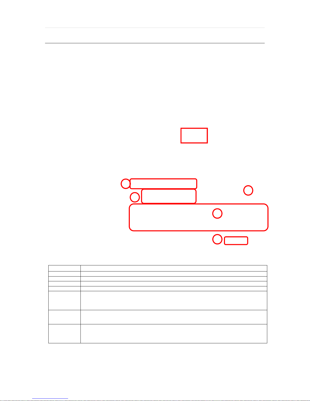
5.3.3 Web Client View
①
②
⑤
⑥
③
④
⑦
⑧
⑫
⑬
⑭
⑩ ⑪
⑨
No. Title Function
1
Connection Mode View the DVR in Live or Playback Mode.
2
Connection Option
3
PTZ
4
Calendar
5
Playback Controllers
6
Audio
7
Export Options
8
Display Options
9
Channel Selection
10
Time bar
11
Time indicator
12
Main Display Area
13
Remote Setup
14
Logout Exit connection from the DVR.
Connect or Disconnect from the DVR.
High quality(Main Stream) or low quality(Second Stream)
PTZ control options, including virtual direction arrows, zoom, focus, and preset
management.
Date & time search.
First data, fast rewind speed, play rewind, pause, play, fast forward speed, and
last data.
Enable/ disable audio.
Export an image, video, or print a still image with notes of a selected channel.
Single channel, 4-channel, 9- channel or 16-channel viewing mode.
Select a specific channel to view in single channel mode.
In playback mode, indicates available recorded video for each channel for the
24 hours of the selected day.
Use the time line indicator to update playback video.
View live or playback from the DVR.
Remote DVR setup options (See 5.2 Web Configuration). Available for admin
users only.
Page 64

User’s Manual | 64
5.3.3 Web Client Operation
User can monitor live video in 1, 4, 9 or 16 screen modes. If user wants to see single channel in full scree n, user can doubleclick on the left mouse button when the cursor is po sitioned on the live video screen. User can change to sin gle mode by
clicking the mode icon located at the bottom left.
Y ou can return to multi- channel vie wing mode by double-clicking any where on the scree n
NOTE
NOTE
The image resolution in “Live monitoring” can be adjusted from the DVR’s ‘Live Stream’ sub-menu under
the Quick Setup Menu. See 4.6 Quick Setup for more information.
If live image does not show properly due to network capabilities or low bandwidth, it is recommended to
close the web page and re-open.
Page 65

65 | Full HD Digital Video Recorder
5.4 Web Playback
Using the DVR’s web client, you can remotely playback vide o from the DVR by clicking “ SEARCH” in the top of the left side
panel. To connect to the DVR in search mode:
1. Check the box next to ‘Search’
2. Press the “Connect” button below the viewing mode .
3. Select the date and time using the calendar on the left side panel. D ays with recor ded data w ill appear in R ed. Click the
button to apply the day selection to the time bar.
4. Play DST- Check this box to play overlapped imag es during DST (Day light Saving Time) period. For further details,
please refer to Section 3.9 DST Settings for more information.
5. Once a day has been selected, the time bar below the main d isplay will show recorded data for each chan nel for t he
selected day . Use the vertica l timeline to mo ve play back along the time bar. The colors on the time bar indicate dif ferent
recording mode. See 3.8.1 Date/ Time Search for more information.
6. Use the playback control keys to play, pause, fast forward or rew ind the video.
Page 66

User’s Manual | 66
6 A
PPENDIX : NETWORK SETUP FOR EXTERNAL USAGE
Please note: The following informat ion are general guideline s. These may vary by network an d router specification s. Contact
your Network Admin istrator or I nternet S ervice Provider for ad ditional in formation.
If you are not connecting to your DVR from within th e same netw ork, y ou will have to perform por t forwar ding on y our router
to access the DVR externally, via the internet.
1. In the [Network] menu set “Network Type” to [Dynamic IP] and click [IP DETECT]. The syst em will automatically
detect the correct settings for the network w here the DVR is in stalled .
2. Once the system generates all the information ba sed on y our network require ments, change the Network Type to
Static and save all the changes as static.
For additional information, and to obtain a proper IP address, contact y our network adm inistrator or Internet
Service Provider .
3. Some internet service providers block port 80 in the ir customer' s routers. Ch anging the w eb port numb er to 81 or
82 is recommended.
4. Access your router by entering its external IP address in y our web brow ser. This information can be found by
running an ipconfig command on your computer's Co mmand Prompt. T he router's extern al IP address is the
GATEW AY addre ss.
5. Check the DHCP settings in your router and setup the DVR f or external conne ctions by performing por t
forwarding. It is highly recommended that you cont act y our Network Administrator for more informa tion and proper
handling of your router. Port forwarding will tell t he router that a ll data r eceived via th ose spe cific ports, wi ll be
redirected to the DVR. For the VMAX A1, you will need to port forward the tw o following ports:
a. Network Port: 81 or 82 (Default was 80)
6. Visit www.portforward.com for additional informatio n on port forw arding for spe cific routers.
7. Visit www.yougetsignal.com to te st whether the p orts have been properly opened. Allow up to five (5) minutes for
the router to update.
8. Once the router settings have been configured, open an internet explor er page and enter your router's external IP
address:DVR's port number (for example: 72.243.193.215:81).
Page 67

67 | Full HD Digital Video Recorder
7 A
PPENDIX : SPECIFICATION
1HDD Type Model 4ch 8ch 16ch
Front Image
Compression H.264
HDD Interface 1 x SATA
Operation System Embedded Linux
Video
Video Mode NTSC
Display Speed 120fps@1080P
Screen Split 1, 4 1, 4, 9 1, 4, 9, 16
Input 4BNC 8BNC 16BNC
Output 1 HD Output, 1 VGA OUT, 1 SPOT OUT
240fps@1080P
120@4k
480fps@1080P
240@4k
Recording
Speed
(NTSC)
Recording Resolution NTSC: 480x240, 960x240, 960x480 / 720P, 1080P, 3M, 4M, 5M
Recording Modes Time-Lapse, Event, Pre-Event, Post-Event, Instant(Panic) Record
Play back &
Search
Audio Input / Output In: 1 x RCA Jack / Out: 1 x RCA Jack
Alarm Input / Relay Output 1 x In / 1 x Relay Out 4 x In / 1 x Relay Out 1 x In / 1 x Relay Out
PTZ Control and Port
Network Transmission
Remote PTZ Control Pan/Tilt/Zoom/Focus/Iris
Main Stream
Speed x1/32, x1/16, x1/8, x1/4, x1/2, x1, x2, x4, x8, x16, x32
Function
LAN 1 x 10/100/1000Mbps Gigabit Ethernet
Mobile S/W Android, iPhone
Max.120fps@1080P,
Max.80fps@3M/4M,
Max.48fps@5M
1, 4
(Multi-Channel Playback)
Date/Time, Record Table, Calendar, Event preview, Bookmark, System log
RS 485 Port 1ea
(PTZ, Keyboard
Controller)
Video Dual-Stream (Local Recording & Network Transmission)
Live monitoring, Remote Playback and File Backup (Triplex-on-Remote)
Virtual Joy-Stick Control on screen(by mouse)
Remote System Reboot by Client(CMS)
Max.240fps@1080P,
Max.160fps@3M/4M,
Max.96fps@5M
1, 4, 9
(Multi-Channel Playback)
RS 485 Port 2ea
(PTZ, Keyboard
Controller)
Remote & E-Mail Notification
Max.480fps@1080P,
Max.320fps@3M/4M,
Max.192fps@5M
1, 4, 9, 16
(Multi-Channel Playback)
RS 485 Port 1ea
(PTZ, Keyboard
Controller)
Page 68

1HDD Type Model 4ch 8ch 16ch 8ch
S/W Central Management System
Remote
Management
Backup
Device
Advanced Function
System Operation Mouse
Temperature
& Humidity
Cerification CE, FCC, WEEE, RoHS, KC
Dimension(W x H x D) 280 x 48 x 245
Web(IE) Live monitoring, Playback & System Configuration
Internal N/A
External
Power 12V x 2A D/C 12V x 3A D/C 12V x 5A D/C
Storage
Operating
Local backup by USB memory stick (2ea) ,
Network backup by CMS support
Multi-Language, System Upgrade by USB & Network,
Help menu on Major Function
Import & Export & Instant File Backup
Warning Alarm for System Over-Temperature
-20 ~ 60℃ / 20 ~ 95%RH
5 ~ 40℃. 20 ~ 80%RH
User’s Manual | 68
Page 69

69 | Full HD Digital Video Recorder
2HDD Type Model 16ch
Front Image
Compression H.264
HDD Interface 2 x SATA
Operation System Embedded Linux
Video
Input 16BNC
Output 1 HD Output, 1 VGA OUT, 1 SPOT OUT, 2 LOOP OUT
Video Mode NTSC
Display Speed 480fps@1080P, 240@4k
Screen Split 1, 4, 9, 16
Recording
Speed
(NTSC)
Main Stream
Max.480fps@1080P,
Max.320fps@3M/4M,
Max.192fps@5M
Recording Resolution NTSC: 480x240, 960x240, 960x480 / 720P, 1080P, 3M, 4M, 5M
Recording Modes Time-Lapse, Event, Pre-Event, Post-Event, Instant(Panic) Record
Speed x1/32, x1/16, x1/8, x1/4, x1/2, x1, x2, x4, x8, x16, x32
Play back &
Search
Function
1, 4, 9, 16
(Multi-Channel Playback)
Date/Time, Record Table, Calendar, Event preview, Bookmark, System log
Audio Input / Output In: 1 x RCA Jack / Out: 1 x RCA Jack
Alarm Input / Relay Output 4 x In / 1 x Relay Out
Virtual Joy-Stick Control on screen(by mouse)
PTZ Control and Port
RS 485 Port 2ea
(PTZ, Keyboard Controller)
LAN 1 x 10/100/1000Mbps Gigabit Ethernet
Video Dual-Stream (Local Recording & Network Transmission)
Network Transmission
Live monitoring, Remote Playback and File Backup (Triplex-on-Remote)
Remote & E-Mail Notification
Remote System Reboot by Client(CMS)
Mobile S/W Android, iPhone
Remote PTZ Control Pan/Tilt/Zoom/Focus/Iris
Page 70

2HDD Type Model 16ch 8ch
S/W Central Management System
Remote
Management
Backup
Device
Advanced Function
System Operation Mouse
Temperature
& Humidity
Cerification CE, FCC, WEEE, RoHS, KC
Dimension(W x H x D) 360 x 66 x 356
Web(IE) Live monitoring, Playback & System Configuration
Internal N/A
External
Power 12V x 5A D/C
Storage
Operating
Local backup by USB memory stick (2ea) ,
Network backup by CMS support
Multi-Language, System Upgrade by USB & Network,
Help menu on Major Function
Import & Export & Instant File Backup
Warning Alarm for System Over-Temperature
-20 ~ 60℃ / 20 ~ 95%RH
5 ~ 40℃. 20 ~ 80%RH
N
The specifications are subject to change without notice
OTE
User’s Manual | 70
 Loading...