

Page 1
USER MANUAL
Rev.0515
※ The picture might differ according to the specification and model.
※ Contents of this user manual are protected under copyrights and computer program
laws.
Thank You!
Before operating the system, please read this User Manual and retain it for future
reference.
Page 2

WARNING
TO REDUCE FIRE OR SHOCK HAZARD,
DO NOT EXPOSE THE UNIT TO RAIN OR MOISTURE.
The installation should be made by a qualified service person
and conformed to all local codes.
Page 3

Cautions
Read Before System Operation
Follow these details to prevent material damage or personal injury.
Signs of Caution and Warning
Warning: This sign indicates that the user could die or be seriously wounded if not used or installed
properly.
Caution: This sign indicates that the user could be wounded or could expect property damage if not
used or installed properly.
Warning: Do not expose the product to fog, rain or too much humid to decrease danger from electric shock
or fire.
General Warning
Warning
1. Use the power cord, which is supplied or recommended by the supplier, or
it may cause fire.
2. Do not disassemble or reassemble the product.
It may cause malfunction or fire.
3. Enquire to your vendor for repair.
It may cause electric shock or fire if the repair is not done properly.
4. Do not touch the product with wet hands.
It may cause malfunction or electric shock.
5. Product installation must be ensured to a professional for product installation, or
it may cause malfunction, electric shock or fire.
6. Ground applies to video products equipped with a 3-wire grounding type plug having a third (grounding) pin.
This plug only fits into a grounding-type power outlet.
If grounding is not done, it may cause malfunction or electric shock.
7. Ground connection must not touch gas pipe, water pipe or telephone line.
If grounding is not done properly, it may cause electric shock.
8. Prevent metallic foreign substance from going inside the product.
It may cause malfunction or electric shock.
9. Do not spray insecticide or flammable spray while driving.
It may cause fire.
10. Place the system in a open place where air ventilation is guaranteed, or
it may cause over-heating and seriously damage the system to be fired.
11. Prevent water from instilling inside electrical parts.
Clean with a dry towel or malfunction or electric shock could result.
Page 4

Caution
1. Use the power cord, which is supplied or recommended by the supplier.
The internal fan rotates at high speed and may cause an accident.
2. Do not drop, give strong vibration, or shock to the product.
It may cause malfunction.
3. The air inhaler of the front panel and air outlet of the back panel must not be blocked during installation.
The internal temperature of the product would be greater than allowable and could cause malfunction or fire.
4. Do not touch the product or the power cord when there is thunder.
It may cause electric shock.
5. Do not install the product near or on top of heating source.
The internal temperature of the product would be greater than allowable and could cause malfunction or fire.
6. Do not install the product on inclined or unstable location or where vibration could be committed.
It may cause malfunction.
Cautions about the Power
Warning
1. Must use the outlet of the grounding to connect the power cord, or
it may cause fire.
2. Do not connect on the middle of power cord or use extension cord.
It may generate heat or cause fire.
3. Do not touch the power cord with wet hands.
It may cause electric shock.
4. Keep power cord dr y and prot ec t fr o m humidi t y.
It may generate heat or cause fire. The power cord is not waterproof.
5. Hold the body of the plug while removing the power plug.
Do not pull the power cord. Damage to the power cord may generate heat or cause fire.
6. Check the power plug regularly.
Humidity and moderation in smoking may cause fire.
7. Remove power cord from outlet when product is not used for a long time.
It may cause short-circuit or electric shock.
Caution
1. Do not turn off the power by removal of the power plug.
To turn off the power, click the power button from the front panel.
When the system stops abnormally, the power button might not work. Click power button for 5 full seconds to turn
power off.
2. Do not cut off the power artificially, or give shock or vibration to unit while the hard disk is activating.
It may cause hard disk failure or loss of data.
Remarks
※ Pictures and buttons are subject to be changed or modified up to different models.
※ Function or configuration is subject to be changed or modified without prior notice for improvement of the product.
Page 5

1 | VMAXAHD CORE™ User Manual
Contents
1. GETTING STARTED ............................................................................................................................................................... 2
1.1 CHECKING SUPPLIED ITEMS .................................................................................................................................................... 2
1.2 SYSTEM STARTUP .................................................................................................................................................................... 3
1.3 BUTTON EXPLANATION ........................................................................................................................................................... 3
1.4 SYSTEM SHUTDOWN................................................................................................................................................................ 7
2. STARTUP WIZARD ................................................................................................................................................................. 7
2.1 LANGUAGE .............................................................................................................................................................................. 8
2.2 DATE/TIME .............................................................................................................................................................................. 8
2.3 HDD FORMAT ....................................................................................................................................................................... 9
2.4 RECORD................................................................................................................................................................................. 10
2.5 NETWORK .............................................................................................................................................................................. 11
2.6 FINISH ................................................................................................................................................................................... 12
3. OPERATION ........................................................................................................................................................................... 14
3.1 USER LOG-IN ......................................................................................................................................................................... 14
3.2 LIVE DISPLAY MODE ............................................................................................................................................................. 14
3.3 PTZ OPERATION .................................................................................................................................................................... 17
3.4 PLAYBACK RECORDED IMAGES ............................................................................................................................................. 18
3.5 QUICK BACKUP DURING PLAYBACK ...................................................................................................................................... 19
3.6 SEARCH RECORDED IMAGE ................................................................................................................................................... 19
3.7 DST SETTING AND IMAGE PLAYBACK ................................................................................................................................... 23
4. SETTING ................................................................................................................................................................................. 24
4.1 SYSTEM ................................................................................................................................................................................. 25
4.2 DEVICE ................................................................................................................................................................................ 33
4.3 EVENT ................................................................................................................................................................................... 37
4.4 RECORD .............................................................................................................................................................................. 41
4.5 NETWORK .......................................................................................................................................................................... 46
4.6 BACKUP .............................................................................................................................................................................. 51
5. WEB SURVEILLANCE THROUGH M/S IE ....................................................................................................................... 54
5.1 WEB LOGIN ........................................................................................................................................................................... 54
5.2 WEB MONITORING ................................................................................................................................................................ 55
5.3 WEB PLAYBACK .................................................................................................................................................................... 56
5.4 SETUP .................................................................................................................................................................................... 57
6. Q & A ......................................................................................................................... ERR OR! BOOKMARK NOT DEFINED.
Page 6
VMAXAHD CORE™ User Manual | 2
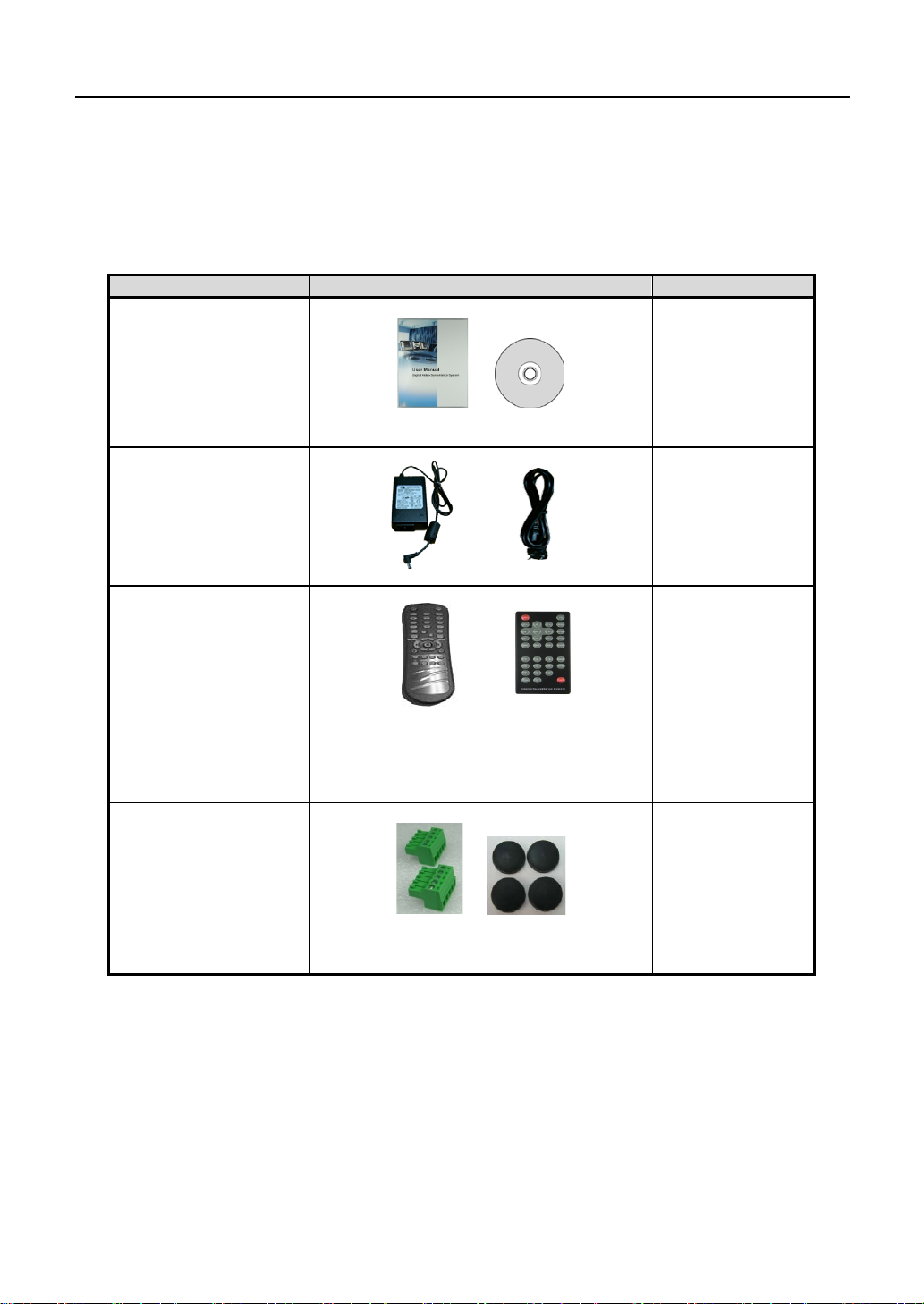
Items
Photo
Quantity
1. Getting Started
1.1 Checking Supplied Items
Make sure that you have following items supplied with your DVR. If any of these items are missing or
damaged, notify your vendor immediately. Keep the packing utilities for moving or storage purposes
afterwards.
User Manual and
Remote Software
12V D/C Adaptor
& Power Cable
IR Remote Controller
Terminal Block
and Rubber Mount
(*) Quick Manual and CD
or
(*) Type of controller may differ
depending on the DVR model
and can be replaced by USB
Mouse.
(*) Packed goods may differ
depending on the DVR model
1 Set
1 Set
1 Set
1 Pair (2 Pieces)
1 Set
*The picture might differ according to the specification and model
Page 7
3 | VMAXAHD CORE™ User Manual
Caution
It may take a few minutes to startup the system after turning on the power. If the network is not
network.
Note
1) Do not forget the administrator’s password that was set for the first tim e. In case the pa ssw ord is
2) Refer to the “Sectio n 4.1.2 U ser” for AUTO LOGIN and AUTO LOGOFF.
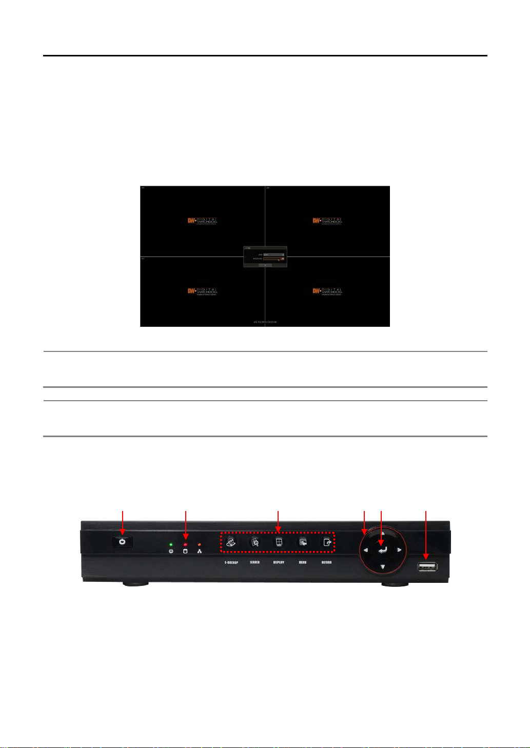
1.2 System Startup
After connecting peripheral devices such as cameras, monitors and a mouse to the DVR, power the DVR by
connecting the 12V adaptor to the device. The login window will appear as shown below.
To login, enter the username and password in the popup screen. There is only one Administrator Account
configurablein the DVR. It is assign ed wit h an un changea ble User ID marked as “ADMIN”. The f actory defaul t
password is “1234”. The Administrator account has full access to the DVR and its configurable parameters
such as creating new users an d ass ign ing r ights to users. If DVR is set a s AUTO LO G IN, login process is not
necessary.
connected or the user sets the network configuration as DHCP when no DHCP server is in the
forgotten, please contact your local dealer for help.
1.3 Button Explanation
1.3.1. Front Panel
*
The picture might differ according to the specification and model
① Power : System ON/OFF
② LED Indicator : Indicates system status.(Power, Record and Network status)
③ Function Button : E-Backup, Search, Screen display mode, Menu, Return
④ Direction Button : Move to the desired menu position
⑤ Enter Button : Select value or setting
⑥ USB Port : For backup, upgrade and so on.
Page 8
VMAXAHD CORE™ User Manual | 4
Note
User can control multiple DVRs with one IR Remote Controller.
(The initial ID is set as “0”.)
Note
How to setup the ID # in IR Remote Controller
For example, press “000” for 0, “023” for 23, “234” for 234.
○
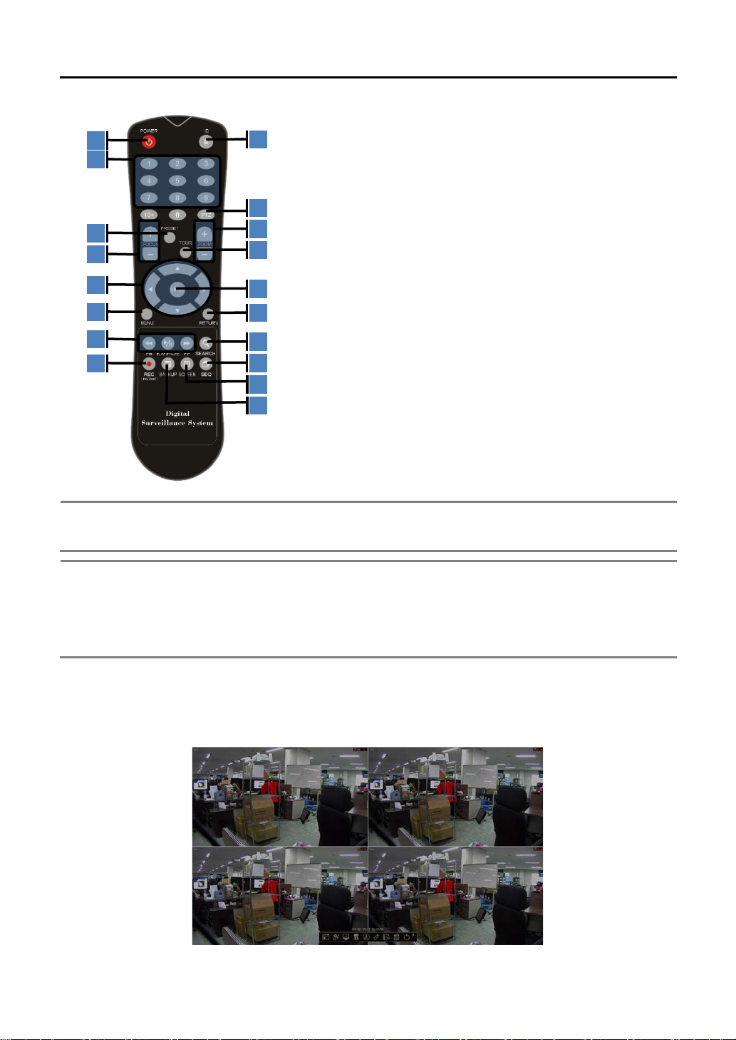
1.3.2. IR Remote Controller
① Power : System ON/OFF
② DVR ID Selection
③ Numeric Button : Channel selection or Password input
④ PTZ Button
⑤ Preset Button : Select Preset on PTZ mode
⑥ Focus Button : Focus IN/OUT on PTZ mode
⑦ ZOOM Button : Zoom IN/OUT on PTZ mode
⑧ Preset Tour : Tour ON/OFF on PTZ mode
⑨ Direction Button
⑩ Enter Button
11
○
13
15
○
○
○
○
○
○
12
14
16
17
18
The picture might differ according to the specification and model
⑪ Menu Button
⑫ Return Button
⑬ Playback Button on Search mode
⑭ Search Button
⑮ Emergency Recording Button
16E
Auto-Sequence Button on Live mode
A
○
17E
A
A○
Screen Mode Button
18E
A○
A Backup Button
In order to control multiple DVRs, each DVR has different Remote ID.
1) Keep pressing ID selection button for about 5 seconds.
2) Set the ID number by pressing numeric button on IR Remote Controller.
ID number is available from 000 up to 255.
3) You have to press numeric button as three-digit nu mber f orm at.
User must set REMOTE ID to match with the ID of the IR remote controller, if the user wants to use it to
control the DVR.
1.3.3. Tool Bar on Live Mode
In live view, move the mouse cursor to the bottom of the screen to show the menu bar as it appears below.
Page 9
5 | VMAXAHD CORE™ User Manual
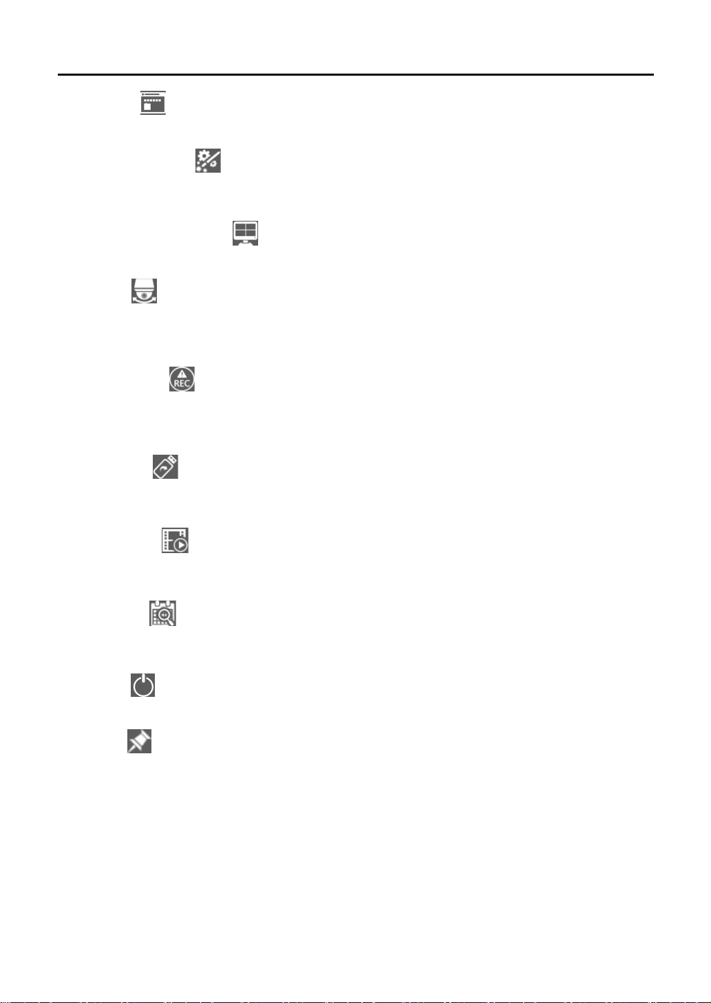
Menu Button
Click on the menu button to access the DVR’s main menu screen. (Please refer to “4. Setting” for details.)
Startup Wizard Button
Click on the Startup menu button to access the Startup Wizard. (Please refer to “2. Startup Wizard” for
details.)
Screen Display Mode Button
Click on screen display mode button to switch screen display mode . Select 1ch, 4ch, 9ch, or 16ch mode.
PTZ Button
Select the PTZ button to control any channel using a PTZ camera. In PTZ mode, you can move pan/tilt and
zoom-in/out by moving the mouse pointer, called virtual joysti ck. Click this button after selecting full screen
mode for the channel. (Please refer to the “Section 3.3 PTZ Operation” for details.)
Recording Button
Select the recording button to urgently start recording. In emergency recording, the system records all
channels with full frame rate at the maximum resolution regardless of recording mode setting. To stop
emergency recording, click the same icon again.
Backup Button
Click the backup button to archive video clips taken during a specific time frame. The video content will be
stored onto an external device. (Please refer to the “4.6 Backup” for details.)
Playback Button
Select the playback button to watch recent video clips automatically. (Please refer to the “3.4 Playback
Recorded Image” for details.)
Search Button
Use this button to search recorded videos with various search modes. (Please refer to the “3.6 Search
Recorded Image” for details.)
Exit Button
User can exit with three different options: Log Off, Reboot and Shutdown.
Pin Button
When selected, the DVR’s menu bar will be display ed on the screen p ermanen etly, regardless of the mouse’ s
position.
Page 10
VMAXAHD CORE™ User Manual | 6
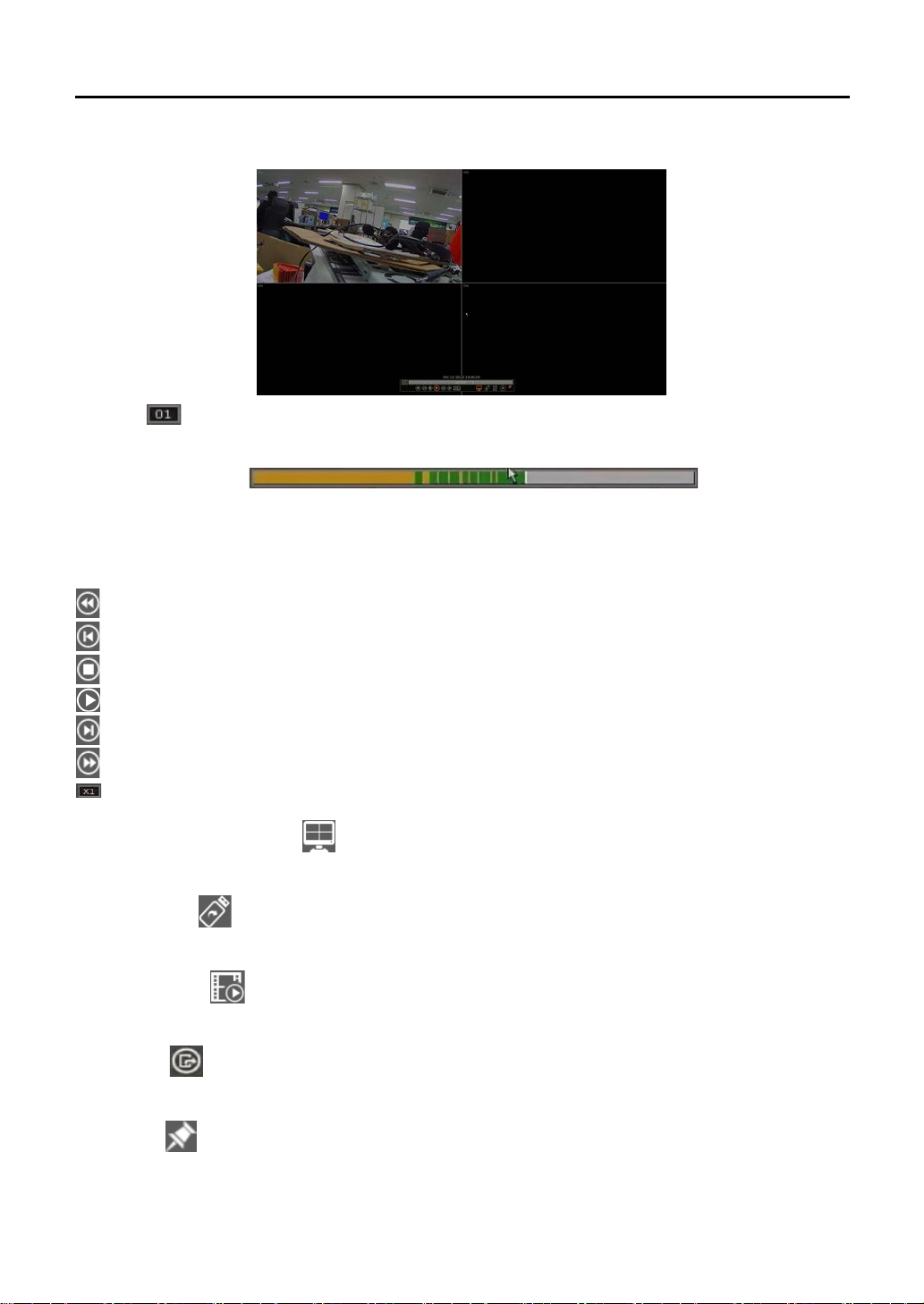
1.3.4. Tool Bar on Playback Mode
In Playback mode, move the cursor to the bottom of the screen to show the menu bar.
Channel
Indicates the currently selected channel.
Intelligent Search Bar
Shows the recording status for the selected channel from 00:00 to 24:00. A white-vertical line indicates the
time which is currently playing. Moving the white-vertical line will update the video.
(Please refer to “Section 4.4. 1 S ched ule” f or detai ls on col ors .)
Playback Control Button
: Playback speed control. (32x / 16x / 8x / 4x / 2x).
: Move backward by one frame
: Stop button
: Play button
: Move forward by one frame
: Playback speed control. (2x / 4x / 8x / 16x / 32x)
: Current playback speed
Screen Display Mode Button
Select the display split mode from the available options. You can select 1ch, 4ch, 9ch, or 16ch mode.
Backup Button
Backup recorded video to the external devices.(Please refer to “4.6 Backup” for the details.)
Playback Button
Switch to playback mode. (Please refer to “3.4 Playback Recorded Image” for the details.)
Exit Button
Close playback mode and move to live mode.
Pin Button
When selected, the DVR’s menu bar will be display ed on the screen p ermanen etly, regardless of the mouse’ s
position.
Page 11
7 | VMAXAHD CORE™ User Manual
Note
User can input password by virtual keyboard, IR remote-control or front numeric buttons (if
available).
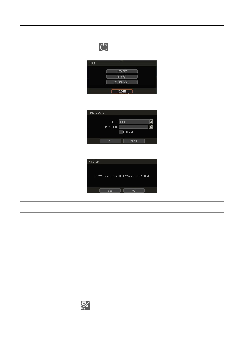
1.4 System Shutdown
To turn off the power, click the exit button [ ] on the tool bar and then click “SHUTDOWN” in the pop-up
screen as shown below. Do not turn off the power by disconnecting the power plug.
Input the password and click “OK” to shut down the system.
And then, click “YES” to confirm shutdown in the pop-up screen as below.
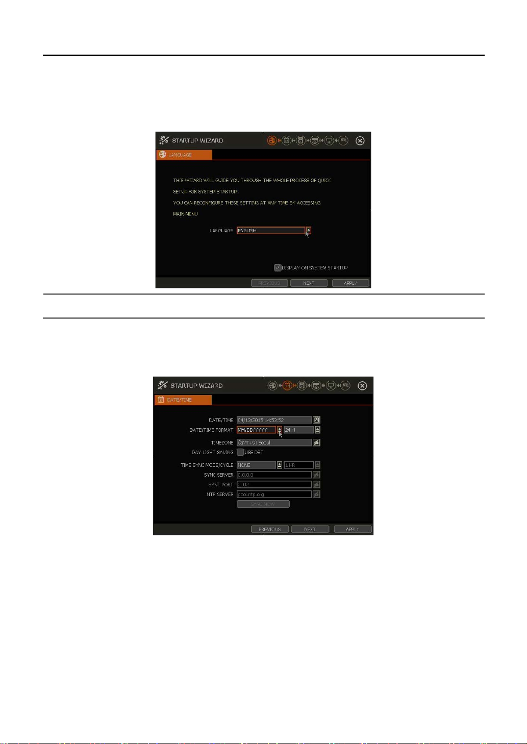
2. Startup Wizard
When the DVR is launched for the first time, the Startup Wizard will appear automatically. This wizard helps
you set up the DVR’s most basic settings for proper functioning. Access the Startup Wizard screen at any
time by clicking Startup Wizard [ ] button in the tool bar
Page 12
8
Note
If “DISPLAY ON SYSTEM STARTUP” is selected, Startup Wizard will pop up every time the
system is started.
2.1 Language
Select the language according to the country or user’s preference. The DVR supports various languages. If
you cannot find your preferred language, please contact your dealer in your area accordingly.
2.2 Date/Time
User’s can control various settings such as time zone selection, DST (Daylight Saving Time) and time sync
mode
TIME SYNC MODE
There are three types of time sync mode.
Server Mode: The operating DVR is set as a Time Sync Server, which can synchronize with the time
of other DVRs connected over the same network.
Client Mode: Input the IP address of a designated DVR as a Time Sync Server in “SYNC SERVER”.
The DVR’s time clock will be synchronized with the server by interval time set in “TIME SYNC
CYCLE”.
NTP Mode: “pool.ntp.org” is the recommended NTP Server. To activate, set the time zone . If you
want to activate this mode, you have to correctly set the TIME ZONE of your local area and then click
button [SYNC NOW].
Page 13
9
Note
1) It may take a few minutes to format HDD.
memory.
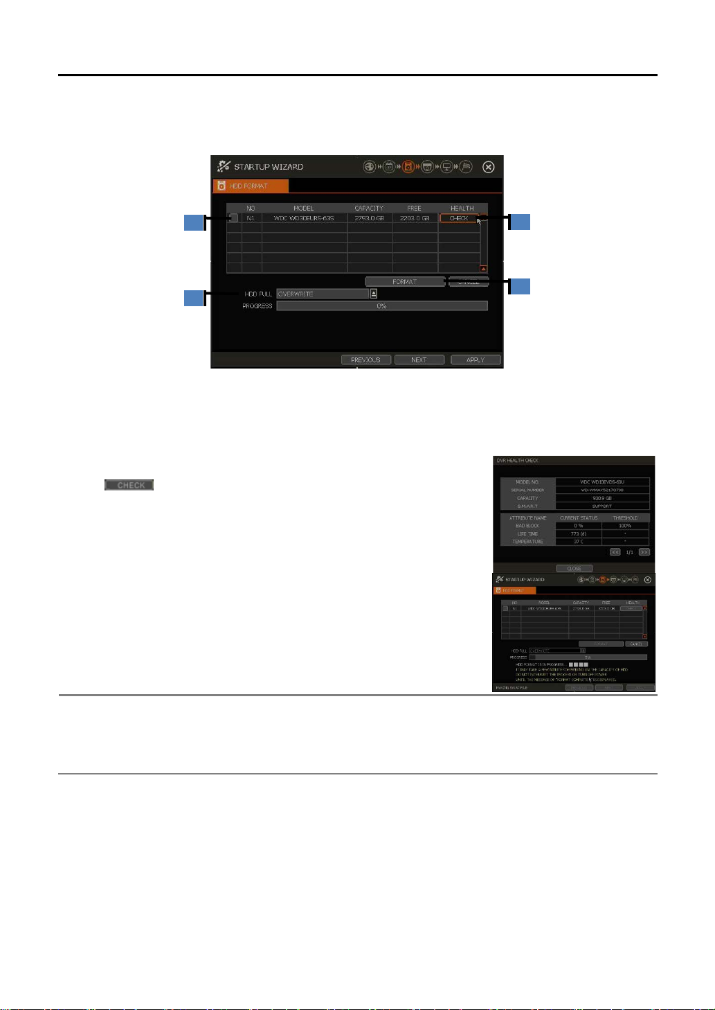
2.3 HDD FORMAT
Digital Watchdog’s DVRs are shipped with pre-installed HDDs that are formatted and ready to be used. There is no need to
format the HDDs out of the box.
HDD FULL (
Select “Overwrite” or “Stop recording” when HDD becomes full.
Overwrite: DVR deletes the oldest data and records new data.
Stop recording: DVR stops recording.
HDD CHECK (
Click ( ) next to each HDD to view full information on ea ch HDD
such as model name, serial no, capacity, bad sector ratio, life time (used
time) and temperature.
HDD FORMAT (
A○
1E
A)
2E
A○
A)
3E
A○
A)
When the new HDD is installed or there seems to be a problem on the
HDD, user needs to format the HDD.
If system resources are occupied such as network connection during
format process, format may fail. It is recommended to reboot the system to
release system resources and then try to format again.
User can select HDD to format by ticking the check box.
If it takes a long time, please check the status of HDD.
2) When the format is done, all data in the HDD will be deleted.
3) The system always reserves some space in each built-in HDD to effectively utilize archiving
Page 14
10
Note
1) VBR (Variable Bit Rate)
: 128K~896KBPS / 1M~3MBPS / Low / Standard / High / Highest / Ex. Highest
Caution
Recordable period (DAYS TO RECORD) in this menu is just for reference and may vary
depending on the actual site situation.
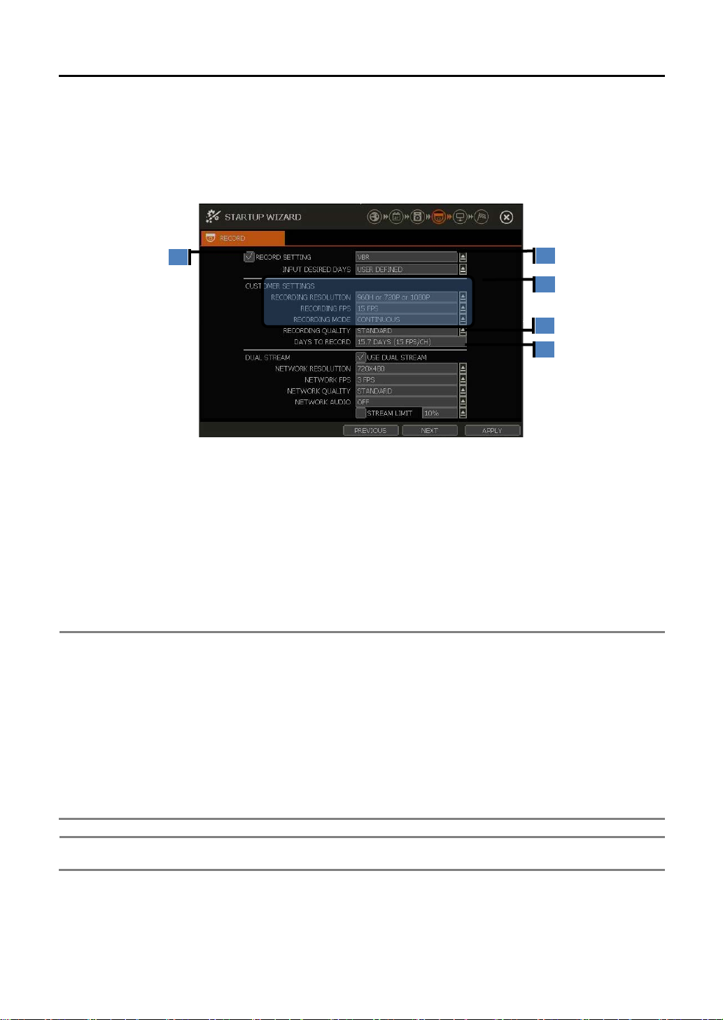
2.4 Record
Users can control simple recording settings for all channels through the Startup Wizard.
It allows you to easily configur e recording resolution, recording speed, recording mode, rec ording quality and
recording periods based on the capacity of HDD installed.
Setting in this menu applied to “Menu > Record> Camera” menu (4.4.1 Camera).
RECORDING SETTING()
If user selects this, the new setting is app lie d to the camera. If not, new setting is not applied to the c amera.
COMPRESSION MODE SETTING ()
User can select “VBR” or “CBR” compression modes.
“VBR” mode allows you to set “INPUT DESIRED DAYS”, recording factors (resolution, frame & quality) are
set to be suitable for the condition, automatically. User can adjust those settings separately (), and then
the expected recording period is shown (
In case of [CBR] mode, user can set recording resolution, frame & mode (). Then, the image quality is
follows the CBR mode. And the expected recording period is shown ().
It focuses on the image quality rather than data size. So, in case of complicated & high
frequency motion image, data size is getting bigger and the recording period is getting shorter.
In this mode, user can change each camera’s quality by selecting one of the following options.
: Low / Standard / High / Highest
2) CBR (Constant Bit Rate)
It focuses on keeping constant data size regardless of the image quality. It can be helpful for
maintaining recorded data as requested period but, in case of complicated & high frequency
motion image, the image quality is getting worse accordingly.
In this mode, user can change all camera’s quality by selecting one of the following options.
) in consideration of the installed HDD capacity.
DUAL STREAM ()
User can set image resolution, frame rate and quality for transmission, separately from those for recording.
(Please refer to the [DUAL STREAM] of menu “4.4.1. CAMERA”)
Page 15
11
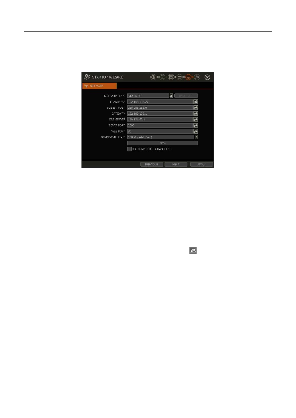
2.5 Network
Set up the DVR’s network settings for remote connection.
NETWORK TYPE
Select either STATIC IP or DHCP for dynamic IP.
If DHCP is selected, the DVR will automatically configure the network settings according to the current
network requirements. If DHCP is selected, click the “IP DETECT” button to automaticaly detect the
network settings.
If Static IP is selected, manually enter all necessary network settings. For proper configuration, it is
recommended to assign the DVR a DHCP address and let it auto discover all the proper network setings,
and then change the Network Type back to Static IP and save the changes.
IP ADDRESS
If DHCP is selected, the IP address will automatically adjust to match the network’s requriements. You can
also manually change the IP address as needed.
If STATIC IP is selected, the user can set IP address for the DVR with button.
SUBNET MASK
Subnet Mask address classifies the subnet that the system belongs to. For more information, please
consult your network administrator or your internet provider.
GATEWAY
This is the IP
through the external router over the internet (from another network). For more information, please consult
your network administrator or your internet
DNS SERVER
Enter the IP address of the Domain Name Server. You should input the DNS Server information in order to
use DDNS, E-mail notifications and NTP Server. If you do not have the correct information, input “8.8.8.8”.
For more information, please consult your network administrator or your internet provider.
TCP/IP PORT
Input the port
blocks the port # 9010, you need to input another valid port number (ex. 9020).
WEB PORT
Input the port number to use when connecting from the Web Browser. Default is 80. If your ISP bl ocks the
address of the network router or gateway server. It is required when connecting to the NCR
provider.
number to use when connecting to the DVR locally or remotely. Default is 1910. If your ISP
Page 16

12
Note
The maximum number of simultaneous connection is 15 users.
Note
For the other network settings, such as DDNS, Notifications, Mobile Push & P2P Cloud, please
refer to the “4.5 Network”.
port # 80, you need to input another valid port number (ex. 8080).
BANDWIDTH LIMIT
Depending on the setting made by user, the system can control the data volume transmitted over network
ranging from 25 kbps up to 1Gbps. This function is effective especially under narrow bandwidth network
conditions or when the user wants to limit “network bandwidth occupied by video transmission” to a certa in
level. Default is 100Mbps.
UPnP (Universal Plug and Play)
UPnP is a feature that allows the DVR to be automatically discovered by a PC on the same network. To
locate the DVR, go to “My Network” on your PC. The computer will scan your network for all supported
devices. The first five characters of the file name of a detected DVR represent the model number, followed
by the DVR’s IP address. This feature may not be support ed i n so me r outers and some netw ork cond itio ns.
Input necessary information based on your network environment.
NETWORK TYPE : Select STATIC IP (in case of fixed IP)
IP ADDRESS : Assign a local IP # to DVR (ex, 192.168.0.164)
SUBNET MASK : Input subnet mask of your LAN (ex, 255.255.255.0)
GATEWAY : Input gateway of your LAN (ex, 192.168.0.1)
DNS SERVER : Input IP # of your DNS server
You must input the IP # for internet connection. Please contact your ISP to
get this IP #. You may also input “8.8.8.8” if you do not know the IP #.
TCP/IP PORT : Default is 9010.
If your ISP blocks the port # 9010, you need to input another valid port
number. (ex, 9020)
WEB PORT : Default is 80
If your ISP blocks the port # 80, you need to input another valid web port
number. (ex, 8080)
BANDWIDTH LIMIT
: Default is 100 Mbps.
Select bandwidth limit you want to set in consideration of network condition.
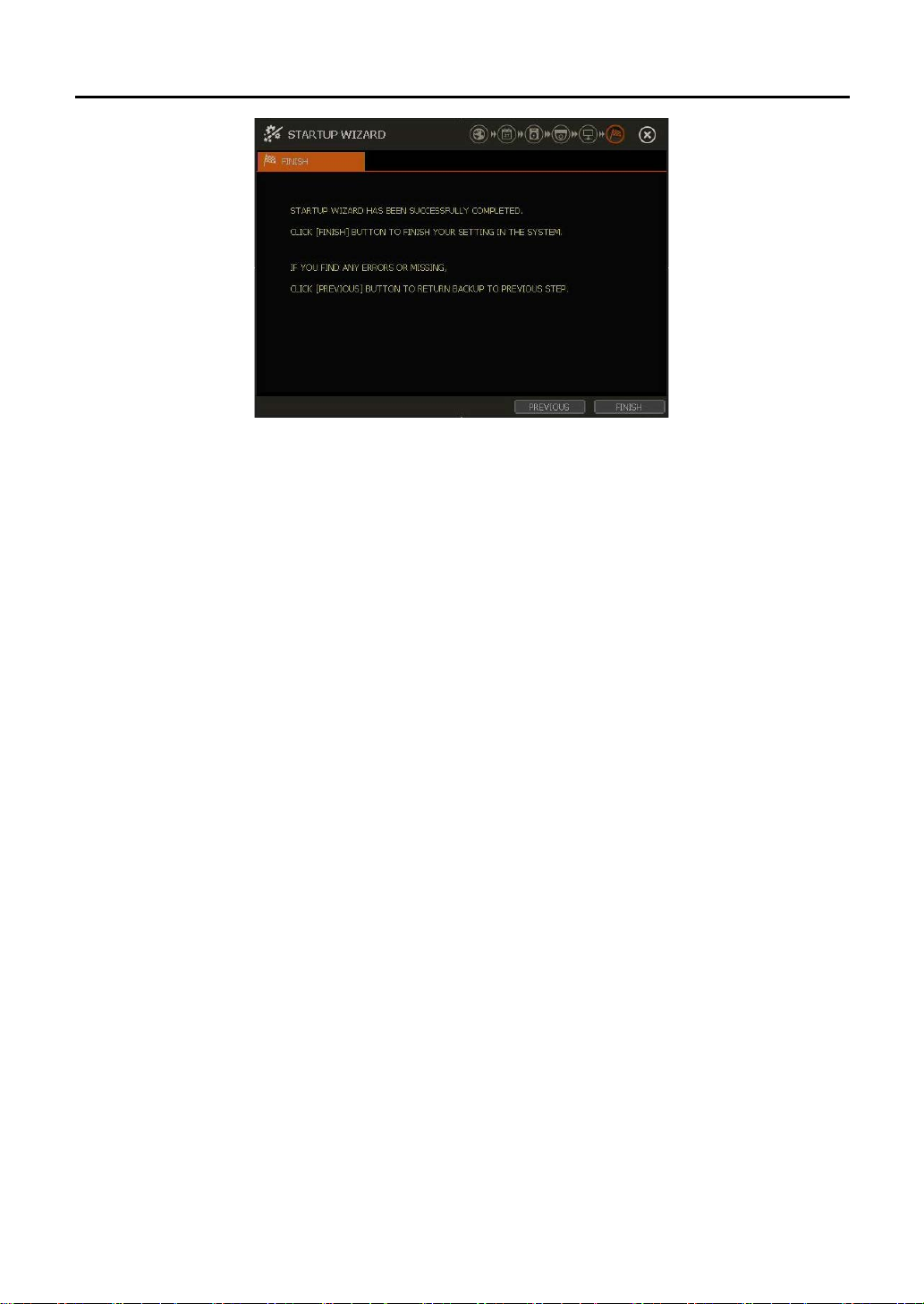
2.6 Finish
Once the setup process is complete, click “FINISH” to close Startup Wizard and go to the live view screen.
Page 17
13
Page 18
14
Note
1) LOGIN window will be permanently displayed until a user logs in with the right ID and
more information.
Note
Some screen mode may not be available.
3. Operation
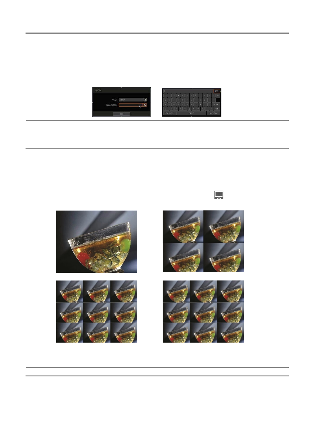
3.1 User Log-in
Input USER and PASSWORD after turning on the system. The factory default of user and password are
“admin” and no password.
password.
2) If the DVR is set as AUTO LOGIN, the login proce s s is not nec essary. See “4.1.2 User” for
3.2 Live Display Mode
3.2.1. Channel Selection
Live image can be seen by using the easy button operation after power-up.
The images can be viewed in 1,4,9, and 16 screen splits. When the up/down arrow button on the front panel
or IR remote controller is pressed and when the screen display m ode button ( ) on the tool bar is clicked,
the screen will be sequentially changed.
[1 Ch] [4 Ch]
[9 Ch] [16 Ch]
To select channel by mouse, simply click. To return to previous screen mode after selecting a full channel,
click of the left mouse button again.
“VIDEO LOSS” is shown on th e display screen w hen n o cam era is c onnecte d or a camera is disconnecte d o n
a certain channel. When a camera is disconnected, a warning sound may be generated depending on the
system settings.
Page 19
15
Continuous + Motion Alarm
Recording
Continuous + Sensor Activating
Recording
Motion Detection + Sensor Activating
Recording
Note
If you cannot find any recording icon in the top right corner of the live screen mode, it means that
. In this case, you need to check recording schedule or
camera of the main setup menu.
Admin users can set diff erent levels of authoriz ation for eac h user. If a certain user is not authorized to view a
certain live and playback channel, then no image is shown on the display screen, as shown below.
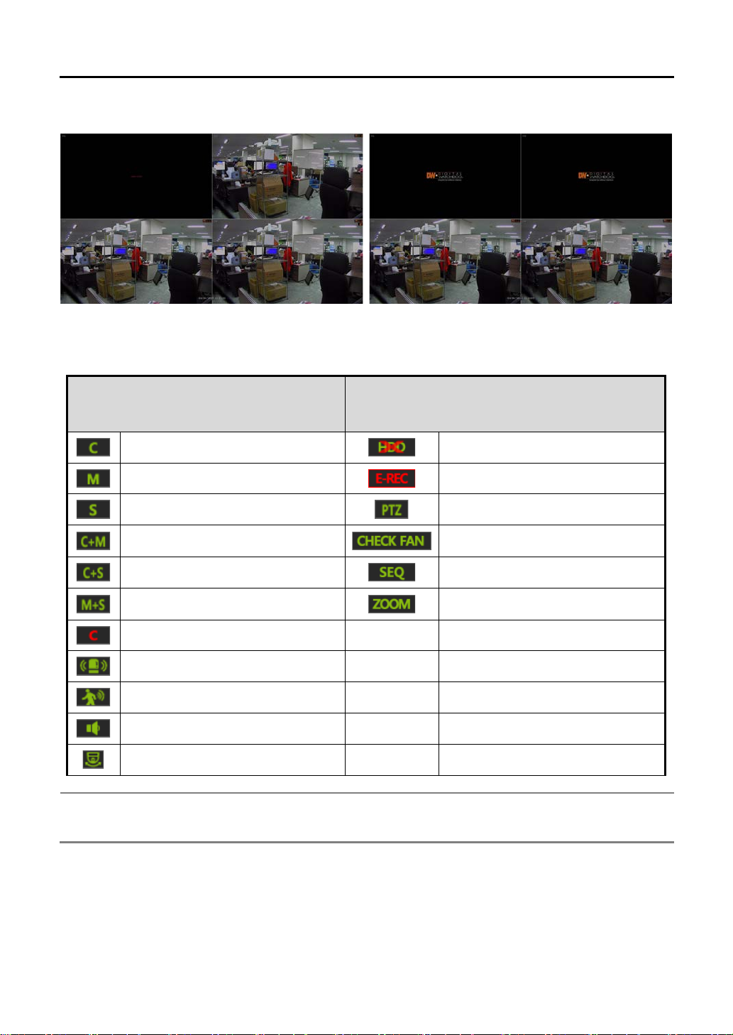
3.2.2. Icons
In real time live mode, ico ns or mes sa ges will be indicated on the scre en to notify the system mode or status.
Below are the icon categories, which are indicated on the monitor.
Icon to be shown
at right-upper corner on each channel screen
Continuous Recording
Motion Detection Recording
Sensor Activating Recording
Emergency Recording
Sensor Activated
Motion Detected
Audio Channel
PTZ Camera
Icon to be shown
at right-bottom corner on full screen
No HDD
Using Emergency Recording
Using PTZ
Warning for ex ceeding temperature
Showing sequence mode
Showing digital zoom mode
.
the system is not recording any video
Page 20
16
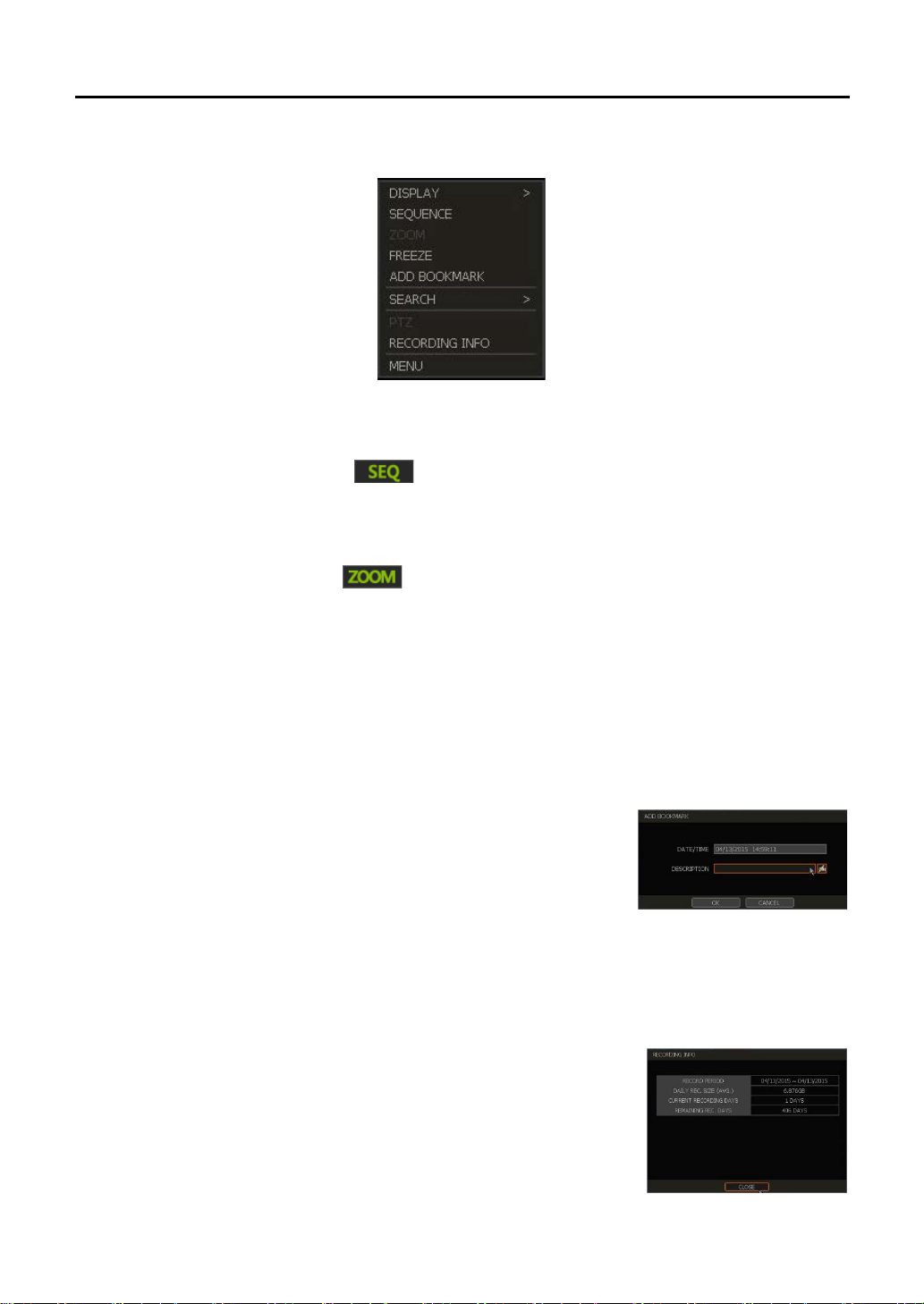
3.2.3. Pop-up Menu
Users can click the right button of the mouse to pop up the sub-menu shown below. For control over specific
channels, move the mouse cursor over t hat cha nnel and click.
DISPLAY MODE
Users can change screen display mode from all of the available split options.
SEQUENCE
When “SEQUENCE” is selected, the icon will appear on the bottom-right corner of the screen an d
the display screen will be sequentially changed.
ZOOM (Digital-Zoom)
Digital Zoom is only available in single channel view.
When “ZOOM” is selected, the icon will appear on the bottom-right corner of the screen and
digital zoom controls w ill be co me available. (It is different from the zoom in PTZ.)
To zoom, right-click on the screen and select zoom from the pop-up menu. Then zoom-in by clicking
and dragging their cursors over the desired area. Users can also zoom-in & zoom-out by mouse wheel
control. Once the image is zoomed-in, users can move that area by clicking and repeating the preious
step.
To exit from the zoom mode, click the right button of the mouse and select “ZOOM EXIT’ in the menu.
FREEZE
Freeze the current live view but allow system clock (date/time information) to continue running at the
bottom of the screen. Select “FREEZE” again to resume the live view.
ADD BOOK MARK
Add a bookmark with a description on the currently displayed image. When
the bookmark menu appears, enter a description and click “OK” to save, as
shown on the right.
SEARCH
Search recorded video using the Calendar, Date/Time, First Data, Last Data, System Log, Event Log and
Bookmark options. (Please refer to “3.6 Search Recorded Image” for details.)
PTZ
Enable PTZ mode. (Please refer to “3.3 PTZ Control” for detail.)
RECORDING INFO
Check the recording status of the DVR such as Recording Period, Daily
Recording Size (A v erage), Recording Days and Re ma ini ng Recording Days.
MENU
Open the main menu setup screen.
Page 21

17
Note
Full PTZ functions are available by using USB mouse, IR remote control, or keyboard controller.
Caution
User can set interval for each preset position.Some preset positions might be skipped in case
it is recommended to make setting of the interval time longer.
3.3 PTZ Operation
In order to operate a PTZ camera, the channel which is connected by PTZ must be in full screen mode.
To activate PTZ control, right-click the mouse button and select “PTZ” in the pop-up men as seen below, or
select PTZ icon in the menu bar. When it is in the PTZ mode, the icon is shown on the
bottom-right corner of the screen.
PTZ Control
In PTZ mode, users can control PTZ cameras with the USB
mouse. While clicking and holding the left button, drag the
cursor up/down or left/rightward to move the camera’s pan/tilt
position. The further away from the center the cursor is moved,
the faster the PTZ camera will move.
To move the camera to a preset position, click the present
position number at the bottom of the screen. The presets must
be set prior to selection.
ZOOM/FOCUS
Zoom in/out by rolli ng the w heel of m ouse to up or dow nw ard. I f user chan ges the m ode
into “Focus” in the pop-up menu, focus can be controlled by rolling the wheel of mouse
as well.
PRESET
When the preset menu pops-up, select the preset number and click “Enter” bu tton to
move to the corresponding preset position.
Maximum Preset number supported is 255 (It can be restricted by the number that PTZ
camera supports).
GUARD TOUR
When enabled, the camera will automatically switch positions according to the sequence of
presets set in the GU ARD TOUR settings .
switching to full screen for the channel that the PTZ camera is connected to. If “GUARD TOUR” is shown
as disabled, check if PTZ camera setting is correct. (Please refer to “4.2.3 PTZ” for more inf ormat ion.)
the camera cannot mechanically move or control focus within the set interval time. In this case,
“GUARD TOUR” can be enabled on the pop-up meny after
Page 22

18
Note
Jog/Shuttle in the front panel may not be available depending on the DVR model.
3.4 Playback Recorded Images
To playback recorded video, pre ss the Play button on the Front Panel, IR remote controller or the playback
icon ( ) in the menu bar. When the DVR returns to playback mode, it will automatically playback the latest
recording video.
It is easy to use a USB mouse or the front panel’s Jog/Shuttle operation to playback recorded files. The
Jog/Shuttle operations allow you to view video in forward or reverse at 1x, 2x, 4x, 8x, 16x or 32x normal
speed.
Date/Time()
Shows date & time of the image that is being displayed, currently.
Tool Bar()
Contains functions such as playback control, r ec orded data check, screen mode and more. (Please refer t o
“1.3.4. Tool Bar on Playback Mode” for details.)
Pop-up Menu()
Display mode : Change display mode (1, 4, 9, 16 screen mode).
Backup : Backup recorded data using the backup window.
Search : Search recorded data by various conditions (Please refer to “3.6 Search Recorded
Image” for detail.)
Add Bookmark : Add a bookmark to the current image and make it easier to locate later.
Live Mode : Go to Live mode
Exit Playback Mode()
In order to exit from the playback mode, click Exit icon in the menu bar.
Page 23

19
Note
[HELP] button can help you understand how to setup several important settings.
Note
There are several ways to get into the search men u.
3.5 Quick Backup during Playback
Easily archive video while watching playback data. While in playback mode, press “ENTER" button in the fr ont
panel to set archive “start” time. After pressing this “ENTER” button, “Quick backup starts” will appear in the
bottom-right of the screen.
Once Quick backup starts, user can keep p lay ing bac k v ideo u ntil user wants to finish archiving, and the n pre s s
the same “ENTER” button again to set ba ckup “end” time. The backup menu window will be appear to complete
the backup. Select the backup media such as CD/DVD or USB thumb drive, and execute archiving.
3.6 Search Recorded Video
User can search recorded video with various conditions.
① In Playback mode, Pop-up menu Search menu.
② In Live mode, Tool bar Search button
③ [SEARCH] button in front panel
Page 24

20
3.6.1. Calendar Search
To search data for a specific date and time, use the Calendar Search window.
Move the white-vertical lin e () to the time that user wants to search.
The colors of the time bar represent different recording modes. Please refer to “4.4.2” for details on colors.
The time bar displays f our ch a nnels at a time. To check another four channels, select the group button on the
bottom of the window ().
“*” mark in date as above picture () means that there is a video data recorded.
3.6.2. Search Date/Time
Enter the desired date and time in the Date/Time Search screen.
Use the arrow button or mou s e to move to each day/month/year and time
category for selecting second / minute / hour / month / year.
Days with recorded dat a will have the “*” mark next to the the m, a s shown on
the right.
3.6.3. First Data
Go to the first screen of the recorded image. This is the oldest image recorded.
3.6.4. Last Data
Go to the last screen of the recorded image. This is the latest image recorded.
Page 25

21
3.6.5. System Log
The system log search is used to find particular system log information such as Syetem, Setup or Network
events.
① Select date to se arch.
② Select log type t o search. U ser ca n search individ ual event s or all a t once.
③ Click [SEARCH] t o show list wit h time and event.
④ Click [EXPORT] to copy the list to external d evice su ch as US B memory stick a s “.txt” file.
⑤ Once the expor t is co mplet ed, a d ate fo lder will creat ed in U SB memory stick. There is “system.log” file stored in
the date folder.
Page 26

22
Note
on another page.
3.6.6. Event Log
Find particular events such as sensor activation, motion detection, video loss or HDD full.
① Select date to se arch.
② Select log type t o search. U ser ca n search individ ual event s or al l at onc e.
③ Click [SEARCH] to show the s earch res ults in list form.
④ Click [EXPORT ] to copy the list t o an external device such as a U SB memory stick as “.txt” file.
20 records will be shown on one page. Click the arrow buttons ( ) to search the log records
3.6.7. BOOKMARK
Bookmark search allows you to check, modify and delete bookmarks.
search results list and click [PLAY] to display the corresponding video.
Select a bookmark from the
Page 27

23
3.7 DST Setting and Image Playback
DST (Daylight Saving Time) begins at 2:00 AM loca l time on the 2nd Sunday of March and ends at 2:00 PM
DST on the first Sunday of November.
During DST, the DVR’s time clock has to be adjusted according to the regional time zone.
3.7.1. DST Setting
To enable DST setting on the DVR, go to the menu of SYSTEM > INFORMATION and click “DATE/TIME ”
to open thw window shown below. Simply check the “USE DST” box to apply the DST time change. (Select
the proper Time Zone that allows the DST setting to be activated.)
3.7.2. DST Image Playback
When there is an hour overlapped data due to DST, the overlapping hour will be indicated in Blue in the
Intelli-Search Bar during playback.
To playback data from the overlapped hour, select a time in th e intelli-search bar . A “Data Selection” message
will appear. Select whether to play DST data or Non-DST data.
Click [OK] to play DST image Click [CANCEL] to play Non-DST image.
[“DST” image is displayed] [“Non-DST” image is displayed]
Page 28

24
Main Classification
Sub Classification
INFORMATION
USER
DISPLAY
HDD
CONFIGURATION
CAMERA
AUDIO
PTZ
KEYBOARD
SENSOR
MOTION ALARM
EVENT ALARM
CAMERA
SCHEDULE
QUICK SETUP
NETWORK
DDNS
NOTIFICATION
MOBILE PUSH
P2P CLOUD
BACKUP
BACKUP
4. Setting
The General setting structure con sis ts of “System”, “Device”, “Event”, “Record”, “Network” and “Backup” as
shown below. Each setup menu consists of sub-menus and additional categories.
SYSTEM
DEVICE
EVENT
RECORD
NETWORK
To access the setup menu, click the button in the menu bar or right-click anywhere on the screen and
select “Setup Menu”. To view the submenus, simply move the cursor over the main menu icons.
Page 29

25
4.1 System
4.1.1. Information
SITE NAME
Enter a site name on the keyboard shown below to differentiate the DVR from other sites.
SITE ID
Setup SITE ID to match the ID settings of a keyboard controller to use it to contr ol DVR.
Ensure that the keyboard model and BUAD RATE are set up in “MENU > DEVICE > KEYBOARD” (Please
refer to “4.2.5 Keyboard” for detail).
REMOTE ID
Setup REMOTE ID to match with the ID setting of IR remote controller , in or de r to use it to control the DVR.
Page 30

26
Note
The “HELP” button can help you understand how to setup several important settings.
DATE/TIME
Manually adjust the date and ti me, sele ct the di splay mode fo r the ti me and da te, a nd sele ct the ap propr iate
time zone. If applicable, check the “USE DST” box.
There are three types of time sync mode.
Server Mode
The operating DVR is set as a Time Sync Server, which can synchroniz e the time clock of other DVR(s)
connected over the same network.
Client Mode
The operating DVR is set as one of the client DVR(s). Input the IP address of designated DVR as a
Time Sync Server in “SYNC SERVER”. Then, the DVR’s time clock will be synchronized with server by
interval time set in “TIME SYNC CYCLE”.
NTP Mode
“pool.ntp.org” is the recommended NTP Server. To activate, set the TIME ZONE of your local area and
then click [SYNC NOW].
For DST setting, please refer to “3.7 DST Time Setting.
LANGUAGE
Select the display language from the available options. If you cannot find your preferred language, please
contact your dealer.
Page 31

27
Caution
Do not click CANCEL button dur ing firm ware upgrade. It may cause serious dam age to
and operating condition of the DVR after firmware upgrade.
Procedure
How to upgrade system firmware using USB memory stick
(*) It is not allowed to use the partitioned USB memory.
VERSION
View the DVR’s current firmware verison and update to a newer version via DVD/CD/USB Memory
Stick/FTP server.
the system!!!
Settings may have been changed to factory default. It is recommended to check the settings
① Input USB thumb-drive which was formatted by FAT/FAT32 in any USB port of DVR
(compatible with USB 2.0)
② Select “USB” from the Method drop down options and press the “Scan” button.
③ Once the system detects the USB drive, it will display the firmware file under
“CURRENT VER” and the “NEW VER”.
④ Click START to begin the upgrade process.
How to upgrade system firmware using Digital Watchdog’s Automatic Firmware
Upgrade via FTP Server:
① Select FTP in the drop-down options under “METHOD”.
② Enter the FTP’s address: ftp.dwcc.tv
should be filled out automatically). Username: vmaxahd, Password: vmaxahd
③ Enter the CHECK TIME that is convenient for you and then click the [SAVE] button.
and enter the username and password (these
Page 32

28
④ The system will automatically check the FTP server for a newer firmware everyday at
user-specified hour and will alert the user if a newer versi on is found .
⑤ Click [START] button to proceed automatic firmware upgrade. After completed, the
system will reboot.
VIDEO SIGNAL
Check the right video signal (NTSC or PAL). This setting should be matched the [NTSC/PAL] Selection
Switch located on the rear panel. Video im ages m ight heav il y shake and bl ink if NTSC/PAL is not properly
set.
IP ADDRESS
Shows the DVR’s IP Address. It can be set at ‘MENU>NETWORK>NETWORK’.
MAC ADDRESS
Shows the unique identity number for the DVR.
KEY PAD BEEP
User can turn on or turn off the beeping sound of key pad.
Page 33

29
Note
Maximum number of users including administrator is 16.
4.1.2. USER
The ADMIN user (default password is no password) has full authority for system setting, allowing this user to
change the system password or add/delete users and assign different permission leves to each user.
User Management
Admin use r can control authorization for each function. This authorization is applied the same when the
user connects to the DVR from a remote software.
① Add User
To add a new user, click the [ADD] button. In the setup window that
appears, set new user’s ID, description, password. Also, select which
functions/menu options the user will have access to allow by checking
the box next to the corresponding functions.
In Live & Playback mode, only selected channels are visible t o monitor
by the user.
To change any settings, select user and click the [Edit] button.
② Delete User
Select a user in the list by highlighting their name and clicking the [Delete] button.
③ Option
If Auto Logon “On Boot” is enabled, the DVR will not request an ID or
password after power up.
If “Auto Logoff” is enabled, the DVR will log off the current user after the set
time of inactivity . Then, the user must login again to operate the DVR.
Example : How to set a user with “Live Monitoring Only”
1) Add a new user name, description and passw ord.
2) Disable all options in [FUNCTION] and [MENU ACCESS].
3) In [LIVE & PLAYBACK], select channel(s) for live monitoring, and click [OK].
4) Click [SAVE].
5) To verify this limite d fu nct ion , log-off through Exit icon and login as the user set above. User can
receive the live images. However, when the user clicks the playback button or selects any other
function, a warning message reading “No Permission for this function” will pop up.
Page 34

30
4.1.3. DISPLAY
Set the sequence dwell time, VGA resolution, OSD display options, spot-out dwell time and spot-out channel
as shown below.
SEQUENCE
Set the dwell time for sequential channel display..
VGA RESOLUTION
The system supports four kind s of vide o res olution s for HDMI and VGA : 800x600, 1024x768, 1280x 1024
and 1920x1080. Set the proper resolution in accordance with the monitor resolution.
OSD
Select what information will appear over the display by checking the corresponding boxes.
SPOT OUT
Select channel to be displayed on spot monitor and set dwell time.
4.1.4. HDD
HDD FULL ()
When an HDD is full, select whether to “Overwrite” or “Stop recording”.
Overwrite : DVR deletes the oldest data and record new data.
Stop recording : DVR stops recording.
Page 35

31
Caution
WARNING MESSAGE
properly, or temperature around the system is properly kept.
Note
1) It may take a few minutes to format an HDD.
memory.
HDD CHECK ()
Click check button ( ) next to each HDD to open the health
check window. See full information for each HDD such as model name,
serial no, capacity, bad sector ratio, lifetime (used time) and
temperature.
To achieve high-level system stability, a warning message of high temperature will be
appear when temperature inside the system exceeds optimum range. This problem may be
driven from a malfunction of ventilation fans. In this case, inspect if the cooling fan is working
HDD FORMAT ()
When the new HDD is installed or there seems to be a problem on the
HDD, formatting the HDD is recommended.
If system resources are occupied such as network connection while the
HDD format is in process, formatting may fail. In this case, re boot the
system and try to format again.
Select the HDD to format by checking the box next to the HDD name
and pressing the format button.
2) When the format is done, all data in the HDD will be deleted.
3) The system always reserves some space in each built-in HDD to effectively utilize archiving
Page 36

32
4.1.5. CONFIGURATION
FACTORY DEFAULT
The system can be reset to its factory default configuration, as long as the user has the authorized
password.
After opening the configurati on window under system , click on t he [DEFAULT] button to initiat e reset. Once,
the factory default is complete, any configuration adjustments made will b e de lete d and the system settings
will return to factory default.
Recorded video data is protected.
EXPORT/IMPORT
System configurations can be copied and pasted in th is menu.
Export : Copy the settings of this system to a removable USB memory device.
Import : T r ansfer the sett ing s found on another system from a CD/DVD/USB memory device.
During the import process, make sure that the F/W version of the sourced DVR is the same as the target
DVR which the settings are being transferred to.
Page 37

33
4.2 DEVICE
4.2.1. CAMERA
Set each camera’s title, covert channel settings and general camera adjustments.
STATUS
Status of each camera is shown automatically when the camera is connected.
TITLE
In order to distinguish each channel from the others, designate a name for each channel. The name will
appear on both the DVR and the remote mo nitor ing sof tware.
COVERT
“Covert,” also called “hidden camera,” hides a camera display and playback as if there were no camera
recording. Covert settings apply to both Live and Playback view so only the administrator can view the
video.
Page 38

34
Procedure
How to setup PTZ camera with Pelco-D protocol (example)
ADJUST
Set the camera’s like brightne ss, contrast, color, etc.
① Click [SET] in the ‘ADJUST’ section to get to the setup window shown below.
② Adjust the applicable settings using the drop-down menu options.
③ To make changes to another channel, use the drop-down menu next to “Camera.”
④ To make changes to all channels, click [Apply All].
⑤ Click “Save” to save any changes made.
⑥ Click [EXIT] to exit.
4.2.2. AUDIO
Select an audio input and output during live display and match it to a designated channel. The number of
audio channels may di ffer depending on the DVR model. Users can he ar au dio sou nd u nd er both liv e di sp lay
and playback mode, depending on the system setting.
Select “USE 2-WA Y AUDIO” to make voice communication between DVR and remote side.
4.2.3. PTZ
Full control of PTZ cameras is available in this menu. For details, please refer to “3. 3 PTZ O perat io n”.
Check the below items for proper PTZ operation.
Check if the protocol of the connected PTZ camera is correct.
Check if the communication setting, including baud rate, m atches the assigned value for that PTZ
protocol.
Check if the address of the connected PTZ camera is correct.
Check if the camera is connected through RS-485 cables.
Page 39

35
1) Make sure of serial communication with the PTZ camera through RS-485 port.
3) Click “Save” button to confirm this configuration.
2) Select “Pelco-D” in the protocol list, and set address.
PROTOCOL
Select the proper protocol of the connected PTZ camera.
BAUD RATE
Select the baud rate level from 2,400bps up to 57,600bps.
ADDRESS
Set the PTZ driver address of the connected camera. It should be the same as that of the PTZ.
CONTROL (The functions are depends on the PTZ model)
When the [SET] button is clicked, the OSD menu of the camera will appear on the monitor. Set the PTZ’s
speed, preset, tour, auto pan, etc.
① Direction buttons: move camera up/down & left/right.
② M (depends on PTZ model): Show/hide camera’s OSD menu on
the DVR monitor. Use the directional arrows to navigate the meny
options.
③ ZOOM/FOCUS/IRIS: Control IN(+)/OUT(-) for each function.
④ Speed: Change the PTZ speed (0~100) and apply it by clicking
[SET] button.
⑤ Preset
Set: Move the camera’s position and zoom to the desired
position. Select the pre set num ber using t he button and then
press the [SET] button. (The s y stem suppor t s preset the nu mber
of preset from 1 to 255.
Move : Select the desired position with the button and click the [Move] button to move the
camera to the preset position of that preset number.
⑥ TOUR : Set the camera to move between preset positions in order. The camera will continuously run
until it is manually disabled.
⑦ AUTOPAN: Set the camera to move 360° in one direction. The camera will keep running the auto-pan
until is it manually disabled.
⑧ GUARDTOUR : Set the camera to move between selected presets in
a set order and interval. The camera will keep running the guard tour
until it is manually disabled.
Set : Set the Inter v al (Sec) and select the desired preset position.
Add to Sequence by clicking the button. The preset wil appear
in the Sequence column indicating the preset number and the set
interval time.
Page 40

36
D elete : To delete a preset position from the sequence, select the preset in the Sequence column
and click the button.
⑨ AUX: Use the [AUX] button to control additional settings such as Power, Light, Wiper & Pump, etc.
4.2.4. KEYBOARD
When an external keyboard is used, select the model and corresponding baud rate from the drop-down
options. The baud rate must match the one set in the keyboard itself. Make sure the Keybaord ID in the
SYSTEM>INFORMATION set up page match the one set in the keyboard.
Page 41

37
Caution
Relay contact can stand up to 24V/1A. If it is connected to an external circuit which is over
24V/1A, the system may experience problems.
4.3 Event
4.3.1. SENSOR
Install multiple sensors on the system t o get th e pre & pos t alarm rec ordi ng along w ith the in tensiv e recordin g
function.
ON/OFF
Turn the sensor on or off.
CAM
Select the associated camera.
OUT
Select the associated alarm output.
INTENSIVE RECODING
When the alarm is triggered, the DVR is switched from recording mode to continuous mode during the
selected dwell time. (Please refer to the “4.4.1 CAMERA” for detail.)
PRESET
Select a preset position for the camera to move to when the sensor is triggered. (See “3.3 PTZ Operation”
menu for additional information.)
DWELL (Post Alarm)
Set the sensor operation time to between 1 and 15 seconds. During this period, the corresponding camera
will record according to the Re cord s et ti ng. The recording stops and alarm outp ut is t ur ne d of f w hen the set
period is elapsed.
PRE-ALARM
Set recording period in seconds just before motion is detected. Input up to 5 seconds of time.
Pre-alarm recording mode is always “continuous” at the recording speed that the user sets in the “Record”
menu.
TYPE
Select the sensor type between N/O(Normal Open) and N/C(Normal Close). The circuit of an N/O sensor
type is usually open, and the activation fo the sensor occurs at the time of close. N/C type works in the
Page 42

38
Note
Check the setting of the sensor type (N/O or N/C). It is recommended to use “Dry Contact Type”
while “Wet Contact Type” may cause the damage to the system.
Note
“Camera pop-up” means that multi-s cree n liv e v ideo mode will be switched to single channel mode
automatically upon alarm triggered. This single channel video is the channel triggered by alarm.
Caution
Relay contact can stand up to 24V/1A. If it is connected to the external circuit which is ov er
24V/1A, the system may experience problems.
opposite way.
NOTIFY
Select how to be alerted when the sensor is activated or motion is triggered by
pressing “NOTIFY” button. The system will generate buzzer sound in the selection
of buzzer and/or make pop-up screen of the camera in the selection of camera
pop-up.
4.3.2. MOTION ALARM
Motion alarm enables the system to begin recording when motion is detected by the cameras. The system
will trigger an alarm signal via the selected sensor-out channel.
ON/OFF
Turn the sensor on or off.
CAM
Select the associated camera.
OUT
Select the associated alarm output.
INTENSIVE(RECORDING)
When the alarm is triggered, the DVR is switched from recording mode to continuous mode during the
selected dwell time. (Please refer to the “4.4.1 CAMERA” for detail.)
DWELL (Post Alarm)
Set the sensor operation time to between 1 and 15 seconds. During this period, the corresponding camera
will record according to the Re cord s et ti ng. The recording stops and alarm outp ut is turned off when the set
period is elapsed.
Page 43

39
Note
Motion detection area and sensitivity should be set, properly, in consideration of the actual motion
happened in the site.
PRE-ALARM
Set recording period in seconds just before motion is detected. Input up to 5 seconds of time.
Pre-alarm recording mode is always “continuous” at the recording speed that the user sets in the “Record”
menu.
MOTION AREA
Set the camera’s motion area and sensitivity. The area can be selected by clicking a specific block and
dragging the cursor across the screen to select multiple blocks. Areas where motion detection is activated
will appear with a green border line. Unselected areas will be shown with a grey border.
Click [SET] in the “MOTION AREA” section to set area.
After selecting the area of motion, click [EXIT] menu(③) and then click [SAVE] button(
change.
To set all channels with the same condition, click [SELECT ALL] button(②) and click [SAVE] button(
save the change.
A○1E A) to save the
A○1E A) to
Page 44

40
Note
S.M.A.R.T(Self-Monitoring Analysis and Reporting Technology) is the techno logy that is developed
HDD. It is recommended to do HDD health check in the HDD menu regularly.
Note
Extra alarm will appear in the event log only when it is set as “ON”.
4.3.3. Extra Alarm
Set up alarms for additional DVR abnormalitites such as SMART HDD check, VIDEO LOSS, RECORDING
FAILURE and DISK FULL.
S.M.A.R.T.
Triggers an a larm signal when H DD is about t o be ou t of op er at ion . Plea se r ef er to t he “Section 4.1.4 HDD”
to check the HDD status.
by HDD manufacturers. In some cases, S.M.A.R.T may not detect the abnormal operation of the
VIDEO LOSS
Triggers an alarm signal when the camera signal is disconnected.
RECORDING FAILURE
Triggers an al ar m signal w hen the syst em does not record images due to an error in the HDD or system.
DISK FULL
Triggers an alarm signal when the HDD is oc cupied w ith a cer tain p ercenta ge of its ca pacity. If the user sets
HDD FULL as STOP RECORDING in HDD menu and the HDD is occupied with the certain percenta ge se t
here, the DVR stops recording and the alarm is triggered.
Page 45

41
Note
1) VBR (Variable Bit Rate)
options: 128K~896KBPS / 1M~3MBPS / Low / Standard / High / Highest.
4.4 RECORD
4.4.1. CAMERA
Adjust the recording settings for each channel separately from the menu shown below.
ON/OFF
This switches “recording” on and off in each channel. If recording is not required on the selected channels,
even when the camera signal is input, set the recording of the corresponding channel as [OFF]. Recording
of the channel stops without disconnecting the camera’s BNC cable.
RESOLUTION
Select the desired resolution for each channel. Users can select eithjer 352×240/288, 720×240/288,
720×480/576 or 960x480/576. As the resolution number increases, the picture quality becomes better. F o r
example, 352×240 is VHS level and when high quality camera is used, 960×480/576 shows DVD level
picture quality. When the picture quality gets higher, the recording file size becomes bigger and the
recording period will be shorter. Thus, selecting appropriate resolution according to the situation is
important.
FPS
The system automatically calculates frames per second (FPS) and displays it as “Remaining FPS”.
Focuses on the image quality rather than data size. So, in case of complicated & high frequency
motion image, data size is larger and the recording period is shorter.
In this mode, the user can change each camera’s quality by selecting one of the following
options: Low / Standard / High / Highest.
2) CBR (Constant Bit Rate)
It focuses on keeping constant data size regardless of the image quality. It can be helpful for
maintaining recorded data as requested period but, in case of complicated & high frequency
motion image, the image quality is getting worse accordingly.
In this mode, the user can change each camera’s quality by selecting one of the following
Page 46

42
Note
recorded before August 11 will be deleted by the system.
AUDIO
Select the associated audio channel.
AUTO DEL (Auto Delete)
When activated, this enables the system to delete video recording that is longer than the number of days
set by “Auto Del”.
“Auto Del” does not guarantee the number of recording days that user set. For example, even
though the user sets “Auto Del” t o 10 day s, if there is not enough HDD space, then the system cannot
record up to 10 days.
If user sets 10 days in “Auto Del” on August 20 for the system that has, for example, 30 days of
video data, then the system will keep video from August 11 to August 20 for 10 days. All other video
USE DUAL STREAM (A○
The DVR can simultaneously generate two independent video streams (one for local recording and the
other for network transmission) for users to effectively manage recording image quality and network traffic.
The frame rate and resolution for each stream can be independently set. For example, users can set
recording settings as “30fps at 960H resolution” while the network setup as “just 1 fps at CIF resolution”.
1E
)
A
RESOLUTION
Select the desired resolution to be transmitted. Higher resolution requires the bigger network bandwidth
due to its data size.
FPS
Select the frame rate to be transmitted. It is not related to the record setting.
QUALITY
Select the image quality to be transmitted. It is not related to the record setting.
Higher quality requires the bigger network bandwidth due to its data size.
AUDIO
Select whether or not to transit audio data by clicking [Yes] or [No].
STREAM LIMIT
Allows users to reduce the image quality for transmission by percentage of the standard quality. Lower
percentages require smaller network bandwidth but image quality will be lower. On the contrary, higher
percentages require the bigger network bandwidth but the image quality will be better. The highest image
quality (100%) is equal to the standard image quality of record setting.
Page 47

43
Note
According to the setup of Resolution and FPS, the system automatically calculates “Remaining
FPS” for dual stream.
Dual stream function is applied to network transmission of the live image monitoring, only. VOD
(Playback) is not related to dual.
Note
4.4.2. SCHEDULE
Set the recording schedule for each camera individually or set for “ALL.” Recording can be set by each hour
from 00 through 23 a day. Y ou can also set up a s pecial re cording schedule for holidays.
NO COLOR (Off)
No color indicated that there is no recording in progress. When a camera is set to “off” in the recording
schedule, the system will not record anything even though the user set recording frames and set the
camera to on in “CAMERA.”
YELLOW (Continuous Recording)
The system records at all times as set in the “CAMERA” settings.
GREEN (Motion-Detection Recording)
The system records only when motion is detected and stops recording when motion is not detected.
If “EVENT > MOTION ALARM” is disable d, then the system will re cor d when motion is detected, b ut m otion
alarm will not be activated.
ORANGE (Sensor-Activated Recording)
The system records only when the sensor is triggered as set in “EVENT > SENSOR” menu.
If “EVENT > SENSOR” and set this mode, then not record anything even though a sensor is triggered.
SKY BLUE (Continuous + Motion Detection Recording)
The system records continuously as set by “RECORD > CAMERA” menu.
When motion is detected according to the settings in “EVENT > MOTION ALARM”, the DVR will switch
recording mode to motion configuration and display a “motion event” message to Remote Software over
the network.
If “EVENT > MOTION ALARM” is disabled, then the system will record when motion detected but the
motion alarm will not be activated.
BROWN (Continuous + Sensor-Activated Recording)
The system records continuously as set by the “RECORD > CAMERA” menu.
When motion is detected according to the setting in “EVENT > SENSOR”, the DVR will switch recording
mode to motion configuration. If “EVENT > SENSOR” is disabled, then the system will begin recording and
Page 48

44
Note
In case the recording schedule is set by “CONT + MOT” or “MOT + SENS”, the system records by
by “MOTION ALARM” or “SENSOR” of “EVENT ” menu.
Note
Dark Blue
Intelli-Search Bar on playback mode.
Note
Instant Recording (Emergency Recording)
recording.
send a “sensor event” notification to Remote Software when a sensor is triggered.
PINK (Motion Detection + Sensor-Activated Recording)
The system records only when motion is detected AND when a sensor is tr iggered at the same time. If both
“EVENT > MOTION” and “EVENT > SENSOR” are disabled, then the system will record only when a
sensor is triggered, but neither motion alarm nor sensor alarm will be activated.
continuous or motion detection mode in normal operation. However, when motion is occurrs in
motion area or alarm is activated, then recording mode will be switch to intensive recording as set
The data recorded during DST (Daylight Saving Time) will be indicated in Dark Blue color in the
HOLIDAY SETUP
Set up specific days as “holidays” in HOLIDAY SETUP to assign special
recording schedules for those days. The system supports up to 32
holidays.
Press [DATE] button ( ), write a description, and then press [ADD] button
to save the date as a holiday.
In case of an emergency, enable “Instant recording” by pressing the panic button in front panel.
The system will instantly start recording all the channels with full frame rate at the maximum
resolution regardless of recording mode setting. will appear in live mode and a
red-colored bar is shown in the time sear ch bar o f play ba ck mode f or th e v ideo r e cor ded by i nsta nt
Page 49

45
Caution
Recordable period calculated by QUICK SETUP is just for reference and may vary
depending on the actual site situation
4.4.3. QUICK SETUP
Users can simultaneously set up multiple cameras with the same confiugrations, including recording
resolution, recording speed, recording mode, recording quality and recording periods based on the capacity
of HDD installed.
① Check the box [USE QUICK SETUP] and set encoding mode (Refer to the menu “4.4.1
CAMERA”).
② Designate the [Input Desired Days] (recording days).
③ The settings for recording resolution, fps and quality will be optimally adjusted accordi ng to the
recording period set in [INPUT DESIRED DAYS].
④ The user also had the option to adjust the settings under CUSTOMER SETTINGS by manually
inputing the settings to get the “Recordable Period” at DAYS TO RECORD based on the capacity
of HDD installed.
Page 50

46
4.5 NETWORK
The DVR can be connected to network or internet through either fixed IP or dynamic IP by proper setting of
DVR and router.
4.5.1. NETWORK
NETWORK TYPE
Select either STATIC IP or DHCP for dynamic IP.
If DHCP is selected, the DVR will automatically configure the network settings according to the current
network requirements. If DHCP is selected, click the “IP DETECT” button to automatically detect the
updated IP address information.
If STATIC IP is selected, manually enter all necessary network settings. For proper configuration, it is
recommended to assign the DVR a DHCP address and let it auto discover all the proper network settings,
and then change the Network Type back to STATIC IP and save the change s.
IP ADDRESS
Displays the DVR’s IP address. If DHCP is selected, the IP address will automatically adjust to match the
network’s requriements. If STATIC IP is selected, users can input IP address by clicking button.
SUBNET MASK
Subnet Mask address classifies the subnet that the system belongs to. For more information, please
consult your network administrator or your internet provider.
GATEWAY
This is the IP address of the network router or gateway server. It is required when connecting to the DVR
through an external router from another network. For more information, please consult your network
administrator or your internet p rov ider
DNS SERVER
Enter the IP address of the Domain Name Server. You should input the DNS Server information in order to
use DDNS, E-mail notifications and NTP Server. For more information, please consult your network
administrator or your internet prov ider.
TCP/IP PORT
Input the port number to use when connecting to the DVR locally o r rem otel y. The default is set to 9010. If
your ISP blocks the port #9010, you need to input another valid port number (ex. 9020).
Page 51

47
Note
The maximum number of simultaneous connection is 15 users.
WEB PORT
Input the port number to use when connecting from the Web Browser. Default is 80. If your ISP blocks the
port #80, you need to input another valid web port number (ex. 8080).
BANDWIDTH LIMIT
Depending on the setting made by the user, the system can control the data volume transmitted over a
network ranging from 25 kbps up to 1Gbps. This function is effective especially under narrow bandwidth
network conditions or when a user wants to limit “network bandwidth occupied by video transmission” to a
certain level. Default is 100 Mbps.
UPnP (Universal Plug and Play)
UPnP is a plug-and-play feature that allows the DVR to be automatically discovered by a PC on the same
network. To locate the DVR, go to “My Network” on your PC. The computer will scan your network for all
supported devices. The first five chartacters of the file name of a detected DVR represent the model
number, fo llowed by the DVR’s IP address. UPnP supports “auto por t for ward function (NAT TRAVERS AL)”
even if the user does not set port forward in the router. It may not be supported in some routers and some
network conditions.
Input necessary information based on your network environment.
NETWORK TYPE : Select STATIC IP (in case of fixed IP)
IP ADDRESS : Assign a local IP # to DVR (ex, 192.168.0.164)
SUBNET MASK : Input subnet mask of your LAN (ex, 255.255.255.0)
GATEWAY : Input gateway of your LAN (ex, 192.168.0.1)
DNS SERVER : Input IP # of your DNS server
You must input this IP # for internet connection. Please contact your ISP to
get this IP#. You can input “8.8.8.8” in case you do not know this IP#.
TCP/IP PORT : Default is 9010.
If your ISP blocks the port # 9010, you need to input another valid port
number. (ex, 9020)
WEB PORT : Default is 80
If your ISP blocks the port # 80, you need to input another valid web port
number. (ex, 8080)
BANDWIDTH LIMIT
: Default is 100 Mbps.
Select bandwidth limit you want to set in consideration of network condition.
Page 52

48
Note
HELP” button will help you understand how to setup several important settings.
menu)
4.5.2. DDNS
Users can use either a public DDNS server or the DDNS server operated by DVR maker
(dynlink.net) to connect through dynamic IP.
DDNS SERVER
Digital Watchdog® offers free and reliable DDNS service support. This allows you to assign the DVR a URL
address rather than a long complicated IP address, simplifying the connection process.
Check the “Use DDNS” box. The default is [DYNLINK.NET] and user can select [DYNDNS.COM] by using
drop-down list. “dynlink.net” is the fixed domain name of DDNS server operated by DVR maker while
“dyndns.com” is one of public DDNS severs. To set up DDNS, follow the following instructions:
Input necessary information based on your network environment. And then click the [SAVE] button.
① Enable “Use DDNS”
② DDNS SERVER : Select DYNLINK.NET.
③ TCP/IP PORT : Default is 80.
④ DOMAIN NAME : Assign domain name for your DVR (ex. DVROFFICE). If the same domain
name is assigned, a message will appear when you click [SAVE].
“
For example, if you need help about how to set D DN S, click “H ELP” button at t he right bott o m of the
IP MAPPING and EXTERNAL IP
If you are using IP Mapping and Port Forwarding (e.g. using router for internet connection), enable both
[Use Device IP Mapping] and [Use External IP] for proper connection.
SETTING AT M/S I/E
In the [Option > Setting], input DDNS address and port number. The DDNS Server address is “dynlink.net”
and the port number is “80”.
In case of using sub domain name, user can type domain name + dynlink.net
.
Ex) 1. If Mac address is “00:1C:84:01:00:02” input as “http://001c84010002.dynlink.net”
2. If domain name is “DVROFFICE” input as “http:// DVROFFICE.dynlink.net”
Page 53

49
4.5.3. NOTIFICATION REMOTE NOTIFY
The system can send an alarm message to the IP address of a Remote Software P/C. Select REMOTE
NOTIFY to use this function and set IP address & events.
E-MAIL NOTIFY
The system can make a notifications directly to a user’s e-mail address.
Select E-MAIL NOTIFY to use this function and set e-mail address & events.
ADD / EDIT / DELETE
User can add/edit/delete e-mail addresses which will receive e-mail notifications.
EVENT
Activate automatic notifications for specific events. When “ALL” is s elected, notifications will be sent for
every event.
SENDER Setting (SMTP)
Set sender to send e-mail notifications.
SMTP : Input the SMTP server address.
PORT : Input the port number that will be used for e-mail sending.
USER : Input the user in case the log-in is required to SMTP server.
PASSWORD : Input the password in case the log-in is required to SMTP server.
Page 54

50
Note
Configuration first priority is alw ay s on “RECORD > SCHEDULE” menu.
mail notifications, set the
“SCHEDULE > RECORD”, “EVENT > MOTION ALARM” and “EVENT > SENSOR” accordingly.
Note
HELP” button will help you understand how to setup several important settings.
bottom of the menu.
FROM : Input the sender’s e-mail address.
E-MAIL TEST : Check if the settings were entered correctly. The DVR will send an e-mail and
inform you of the result.
1) Results arrive at varying times depending on the SMTP se rver’s resp onse
time.
2) In some cases, SMTP server does not send e-mail if the e-mail is receiv ed.
Use SSL AUTHENTICATION: In case the SMTP server requires SSL authentication
(e.g. Gmail, Yahoomail, etc.), select this option.
Thus, the system w ill no t e mai l alarm message upon motio n alar m or se nsor even though the user
checks the event selection box. To receive motion and sensor e-
“
For example, if you need help about how to set up a notification, click “HELP” button at the right
Page 55

51
Note
It is recommended to use built-in CD/DVD burner or well-known major brand of USB thumb drives
2) It is not allowed to use the partitioned and/or password-encoded USB memory.
Note
“HELP” button will help you understand how to setup several important settings.
the menu)
4.6 BACKUP
4.6.1. Manual Backup
Easily archive video while viewing the video playback.
① In live mode, click the [BACKUP] icon in the menu bar to open the backup menu.
② In playback mode, press the [QUICK BACKUP] icon in the menu bar. Pressing it once will indicate
the start time for the backup file. Click the icon again to indicate the end time for the backup clip.
The backup menu screen will appear as shown below.
③ Connect an appropriate USB memory device like USB thumb drive, built-in CD or USB ODD burner
and press [SCAN] button to get the system recognize it before actual archiving. Necessary file si ze
will be shown before burning.
④ Adjust the following options a s needed:
a. Select the channels to be included in the backup file.
b. Adjust the start and end time of the backup file.
c. Press the ‘Estimate’ button to see the expected size of the backup file.
d. Check the box next to [ADD VIE WER] to add the backup player to the bac ku p file. The backup
player allows to play the video clip without installing any programs.
e. Edit the file name and add a protection password if needed.
f. Press [BACKUP] to start the backup process. A progress bar will appear on the screen.
formatted by FAT/FAT32 for proper backup.
1) The system does not detect external HDD due to different format type.
For example, if you need help about how to set Backup, click “HELP” button at the right bottom of
Page 56

52
4.6.2. Backup Video Retrieve
If [ADD VIEWER] is selected, the backup image can be reviewed on a PC with no need for additional
installation. Once the backup device (USB, CD/DVD) is connected to the PC, the files will appear in the
USB’s folder.
To play recorded data, double c lick the “MultiBackupPlayer.exe” file. Then, in the backup player, open the
video data file (SSF format) you wish to playback in the date folder.
1E
A○
To playback a single channel, click the [SINGLE CH] tab (
the viewing area.
To playback multiple channels, click the [MULTI CH] tab (
A) and select a SSF file to playback and drag it to
1E
A○
A) and ‘Search” to open folder that keeps SSF file.
2E
A○
Users can print, export an image, and zoom in/out by using the icons(
A) on the bottom-left of the player
window.
Option MENU
V ar ious set ting s are available in the OPTION window of the backup player software.
Use DirectDraw
There are some PCs that do not support “Direct Draw”. In this
case, users can uncheck the DirectDraw check-box in the
“Option” menu.
Show Image Info on Snapshot
Image information will be added as text overlay when exporting
an image.
Show POS Data on video channel
POS data that has been backed up can be displayed during playback.
Page 57

53
No alteration was found on
original A VI video clip
A VI v ideo clip has b een
altered
WATERMARK Verification on AVI File
Convert the backup file from SSF format to AVI format to play the file in ordinary media programs.
1) Playback the SSF file in Single CH mode, click [Pause].
2) Click [AVI Convert].
3) Define the start time and end time.
When the AVI file is played back in the BackupPlayer, verify whether the AVI file has been altered or not by
pressing the [Watermark] button ( ). If the file has been altered, a popup message will appear.
Page 58

54
5. Web Surveillance through M/S IE
The system has a built-in web server by itself. This allows you to access the system using an ordinary
web-browser via network for live monitoring, playback or remote configuration without installing any
additional software.
5.1 Web Login
In an Internet Ex plorer pag e, type the DVR’s IP address or DD NS addre ss in the address bar. When the l ogi n
page appears, enter the user ID and password. The default user ID and password are “admin” and no
password. After login, download & install Active-X file
.
Active-X Installation
1. If the P/C doesn’t have Active-X installed, an installation guide message will automatically appear,
prompting you to install the latest version of Active-X.
2. Click “install” and follow the installation wizard to complete the Active-X installation.
3. To avoid download restructions, make sure that Active-X controls are enabled in the web browser’s
security settings. Go to “Tools > Internet Options > Security > Internet > Customer Level” and enable all
Active-X controls and plug-ins as shown below.
Page 59

55
5.2 Web Monitoring
Once the Active-X files are properly installed, the live view from the DVR will appear on the web page
automatically. Users can select other menus such as PLAYBACK and SETUP, or LOGOUT.
LIVE
Users can select which channels to view in live mode, set the reconnection time interval in case of
connection loss, and connect or disconne ct all cha nnel s.
PTZ CONTROL
Users can control Pan/Tilt, Zoom In/Out, Focus In/Out and Preset buttons to control PTZ cameras
connected to the DVR.
FUNCTION
Enable or disable audio in from the camera.
Enable or disable interlace function to improve image quality.
HIDE MENU/SHOW MENU
To hide the menu bar, press the “HIDE MENU” button. To view the menu bar again, press the “SHOW
MENU” button.
POP-UP MENU
Right-click to open additional options:
Display Mode: change the current s plit view option from 1x , 4x,
9x, or 16x options.
Full Screen: View current split view in full screen view.
Right-click anywhere on the screen to exit full scree n view.
Original Screen Ratio: view the cameras in their orig inal as pect
ratio.
Archive: Backup a clip to your PC. Click the screen once to s ta rt the backup. Selec t the
directory whe re you want the files to be stored. Click the Archive option again to end th e
backup process. A popup screen will ask you to sav e the a rchive or not.
Page 60

56
5.3 Web Playback
Users can remotely playback the DVR video by clicking “PLAY” button in on the top of the window.
PLAYBACK TIME
Select the date/time and click the “GO” button to view video from the selected time.
PLAYBACK ICON
Play/Pause is toggled and playback speed is shown on the right box.
PLAY DST
Check this box to play overlapped video during DST (Daylight Saving Time) period.
For details, please refer to Section “3.7.DST Setting and Image Playback”.
INTELLI-SEARCH BAR
Move the red-vertical line to the desired time you want to search.
The colors of the time bar are different by each recording mode. Please, refer to Section “4.3.2” for details
on colors.
Page 61

57
INFORMATION
USER
DISPLAY
CONFIGURATION
CAMERA
AUDIO
KEYBOARD
SENSOR
MOTION ALARM
EXTRA ALARM
CAMERA
SCHEDULE
QUICK SETUP
NETWORK
DDNS
NOTIFICATION
5.4 Setup
[Menu of Setup]
Main Classification Sub Classification
SYSTEM
DEVICE
EVENT
RECORD
NETWORK
After logging in with the right ID and password, users can adjust various configurations in the Web Setup
window shown below. This Web Setup is only available to the “admin” account.
[System] [Device]
[Event ] [Record]
Page 62

58
Note
This DVR system has its own built-in web server.
regardless of Internet connection.
Note
<System Reboot> enables user to reboot the system without any change of the setup.
case of DHCP mode.
[Network]
Therefore, this web CGI screen is directly supported from the built-in web server of DVR
User can use this function when the network is disconnected due to abnormal operation of the
system and try to reconnect. However, the IP number assigned to the system may be changed in
Page 63

59
6. Frequenty Asked Questions
1. Why doesn’t the DVR record images in sensor mode and/or motion mode?
1) It records images only when there is an event for the corresponding mode.
2) Please check if the setting is correctly done at the menu of [Event > Sensor],
[Event > Motion Alarm], and [Record > Schedule].
2. There is a HDD installed but the “No HDD” icon( ) is still shown on the screen.
1) Please check the cable connection of the HDD again.
2) If you can see the HDD list at [System > HDD] but the capacity indicates “0”, it means that the HDD
requires formatting.
3. Why is there nothing displayed on the HDMI / VGA monitor, even though the power is
connected?
1) Please check if the power is supplied properly. When the power is supplied, you can hear the noise
from FAN and HDD operation.
2) Please check the HDMI / VGA cable connection with the DVR. Remove all the cable connections,
except for the monitor cable, and then apply power to the DVR again and check booting status.
3) Please check if the option [VGA] is selected at the rear panel of DVR.
4) In case that the display screen is stopped at logo screen, please contact your dealer or distributor.
4. How do I establish a PoE connection (xDSL, cable and so on)?
1) There is no function to log-in at the DVR.
2) Please use a router which supports PoE log-in.
5. Is it necessary to open the por t when using DDNS (dynlink.net or dyndns.org)?
Yes, it is.
DDNS is the function that lets remote software acknowledge the changed address of the DVR (dynamic
IP provided by ISP) or to allow connection to the DVR by domain (domain.dynlink.net) without
memorizing IP.
6. Remote software connection to the DVR works fine but WEB connection doesn’t work.
1) Some ISPs block port number 80. Please try again after changing WEB port.
(8080 is recommended.)
2) Please check whether the port number 80 is opened or not.
7. Why isn’t the image showing after login at WEB monitoring?
TCP Base port should be opened. Default of TCP base port is 9010.
8. The image on remote software suddenly disappeared a fter displaying for a short time.
1) Some ISP restricts upload data/traffic volume. Please contact your ISP.
2) Upload traffic restriction can be easily checked with the following steps.
① Turn off the power of Modem & Router.
② After some time (1~5minutes), turn on the power of Modem first and then Router.
③ After reconnection, if it is disconnected again after a short time (in a similar period later), it
means that the ISP restricts upload traffic.
Page 64

60
9. Why can’t I backup or upgrade firmware through my USB memory stick even though it
is detected by the DVR?
1) Make sure the USB memory stick is formatted by FAT or FAT 32.
2) It is not allowed to use partitioned and/or password-encoded USB memory sticks.
10. Why won’t the firmware upgrade using a CD?
1) DVR detects the files only when they are in root directory.
2) Files in sub folder cannot be detected.
3) It is recommended to upgrade firmware with USB memory stick.
11. Why won’t my Time sync work through NTP server?
NTP server requires DNS server address. Please check if DNS server address is correct
at [Network] tab.
12. Why am I not receiving notifications via E-mail transmission?
1) E-mail notification function work based on SMTP service.
2) Please check if the sending mail address is correct and if the mail server supports SMTP service.
3) In case using SMTP service which is based on TLS authentication (including SSL) such as Gmail
and yahoo mail, please enable [Use SSL Authentication at [Notificat ion] tab.
4) SMTP service is provided based on DNS. Please check if the DNS server address is correct on the
[Network] tab.
 Loading...