

Page 1
ABOUT MANUAL
Before installing and using the camera, please read this manual carefully.
Be sure to keep it handy for future reference.
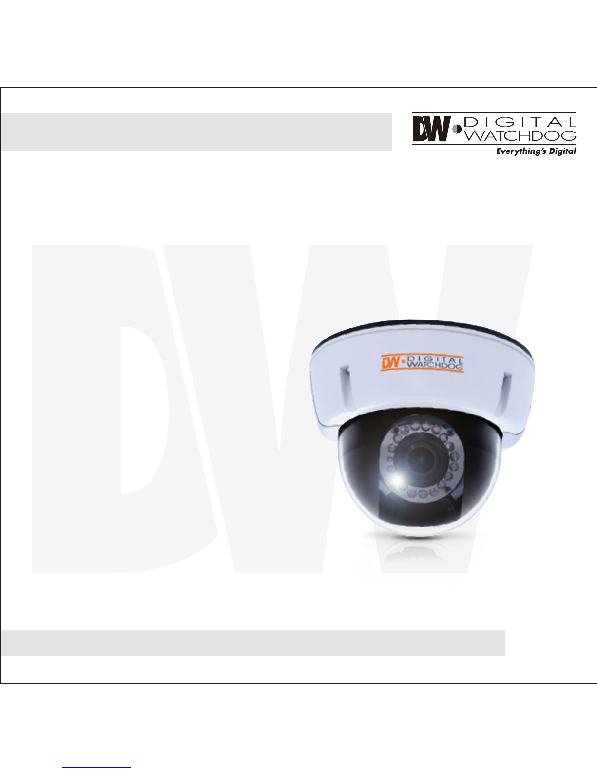
High Resolution
Vandal-Proof Dome Camera
DWC-V1362DIR
08092012
Page 2

2
PRECAUTIONS
FCC COMPLIANCE
Do not open or modify.
Do not open the case except during maintenence and installation, for it may be dangerous and can
cause damages.
Do not put objects into the unit.
Keep metal objects and flammable substances from entering the camera.
It can cause fire, short-circuits, or other damages.
Be careful when handling the unit.
To prevent damages, do not drop the camera or subject it to shock or vibration.
Do not install near electric or magnetic fields.
Protect from humidity and dust.
Protect from high temperature.
Be careful when installing near the ceiling of kitchen or a boiler room, as the temperature may rise
to high levels.
Cleaning:
To remove dirt from the case, moisten a soft cloth with a soft detergent solution and wipe.
Mounting Surface:
The material of the mounting surface must be strong enough to support the camera.
This equipment has been tested and found to comply with the limits for a Class B digital device,
pursuant to part 15 of the FCC rules. These limits are designed to provide reasonable protection against
harmful interference. when the equipment is operated in a residential environment. This equipment
generates, uses, and radiates radio frequency energy; and if it is not installed and used in accordance
with the instruction manual, it may cause harmful interference to radio communications.
WARNING: Changes or modifications are not expressly approved by the manufacturer.
Page 3
TABLE OF CONTENTS
3
Introduction
Installation
Troubleshooting
Warranty Information
Memo 22-23
Specifications
Features
Parts and Descriptions
Dimensions
Inside the Box
Mounting the Camera
Connecting to Monitors
Adjusting the Camera Lens
4
5
6
7
8-12
13
14
17
18-19
20-21
Camera Control Board 16
Adjusting the 3-Axis Gimbal 15
Page 4
4
FEATURES*
1/3” CCD
570 TV Lines [B&W], 540 TV Lines [Color]
3.3~12mm Varifocal Auto Iris Lens
100ft Range IR with Intelligent Camera Sync
Electronic Day and Night
3D-DNR (3D Digital Noise Reduction)
D-WDR (Digital Wide Dynamic Range)
HME (Highlight Masking Exposure)
SLC (Side Light Compensation)
Programmable Privacy Zones & Motion Detection
AGC / BLC / AWB
Easy Icon Driven OSD Menu with Built-in Joystick
IP66 Certified (Weatherproof)
Auto Sensing 12VDC/24VAC with Line Lock
Secondary Video-BNC Output
Page 5
5
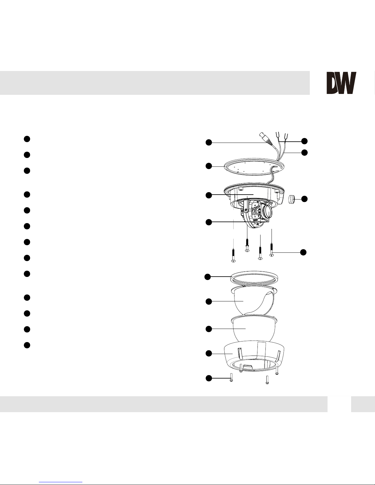
PART & DESCRIPTIONS*
1
2
3
4
5
6
7
13
12
11
10
9
8
Lens
Video Output Connector - BNC
Power Input Connector
12VDC/ 24VAC Dual Voltage
RS485: BK(D+), WH(D-)
Rubber Band
Black Dome Insert
Bubble Dome
Upper Case
Assembly Screws
T20 M4X16
NPT Plug
Bottom Case
Rubber Pad
Mounting Screws
1
2
3
4
5
6
7
13
12
11
10
9
8
Page 6
6
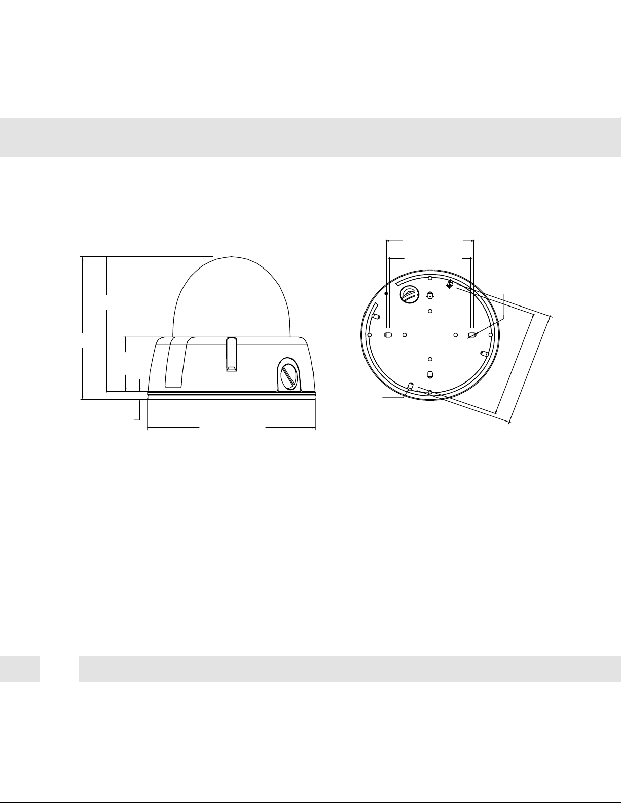
DIMENSIONS IN MILLIMETERS (IN)*
109.6(4.31”)
103.1(4.06”)
41.3
(1.63”)
6.5(0.26”)
145(5.71”)
117.0(4.61”)
125.0(4.92”)
5.0(0.2”)
4.5(0.18”)
91.0(3.58”)
85.0(3.35”)
Page 7
7
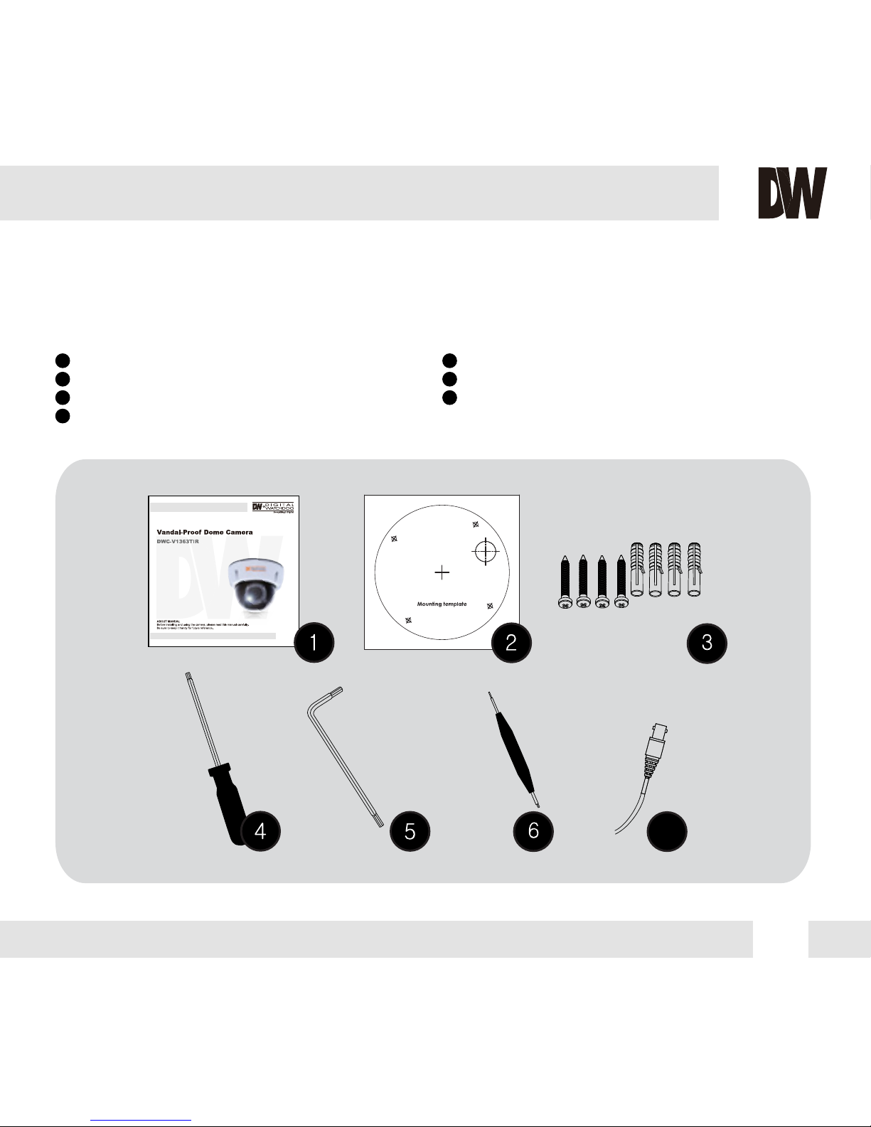
INSIDE THE BOX*
Included with V1 Vandal Dome Camera
1
2
3
4
5
6
7
User Manual
Mounting Template
4 Machine Screws and 4 Dry Wall Anchors
TORX-T20 Hex Key
Double-Sided TORX-T20 Hex Key
L-Key
Secondary Video-BNC Cable
7
Page 8
8
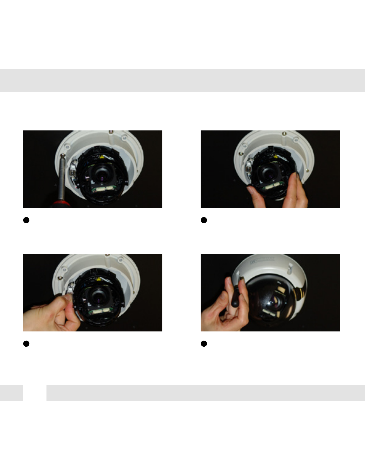
MOUNTING INSTALLATION INSTRUCTIONS*
Pull wires through and make connections.
Refer to page 13. Use mounting template to
mount camera with drywall mounts and
machine screws.
Adjust the camera (pan, tilt, zoom). See
page 14 for details.
Use the joystick to adjust the OSD menu.
See pages 15-17 for details.
Attach the camera housing to the junction
box using the assembly screws.
1 2
3 4
Page 9

9
JUNCTION BOX INSTALLATION INSTRUCTIONS*
Check to see all parts are in
the box.
Use the dry wall anchors and
machine screws to mount the
junction box and rubber
gasket to the wall.
Insert wires through the
wall and make the
appropriate connections.
Attach the camera to the
junction box using the
machine screws.
Attach the camera housing
to the junction box using the
assembly screws.
1 2 3
4 5
Page 10

10
WALL MOUNT INSTALLATION INSTRUCTIONS*
Check to see all parts are in
the box.
Insert the wires from the
camera through the wall
mount housing.
Attach the camera to
the wall mount housing.
Use the mounting template to
make pilot holes. Use the dry
wall anchors and machine screws
to attach the assembly to the wall.
Attach the camera housing
to the fixture.
1 2 3
4 5
Page 11

11
PENDANT MOUNT INSTALLATION INSTRUCTIONS*
Check to see all parts are in
the box.
Attach the top shield to the
pendant mount.
Slide the wires from the
camera through the pendant
mount.
Attach the camera to the
pendant mount using the
machine screws.
Attach the camera housing to
the fixture.
Use the mounting template to
make pilot holes. Mount the
camera assembly to the ceiling
using wall mount anchors and
machine screws.
1 2 3
4 5 6
Page 12

12
CORNER MOUNT INSTALLATION INSTRUCTIONS*
Check to see all parts are in the box. Attach the two compression fittings to the
corner bracket.
Attach the wall mount to the corner bracket
with the 4 machine screws.
Attach the seembly to a wall corner with dry
wall anchors and machine screws.
1 2
3 4
Page 13

13
CONNECTING TO MONITORS*
Power Connection: 12VDC & 24VDC Dual Voltage (Auto Polarity Detection and Protection)
All cameras are equipped with a second video output for on-site configuration.
Use the diagram below to connect to a Monitor or CRT Monitor properly.
Video Output BNC Cable
Main Monitor
Field Test Monitor
Spot Monitor Cable
DC12V / AC24V
300mm(11.8”)
Page 14

ADJUSTING THE CAMERA LENS*
Follow the instructions below to make any lens adjustments.
14
Loosen the zoom and focus handles by rotating them counter-clockwise.
Adjust the field of view by moving the handle to the RIGHT (tele) to zoom in or to the LEFT(wide)
to zoom out.
AFTER the desired zoom position is established, adjust the focus the same way as described
above.
Once the desired adjustments have been made, please tighten the handles back by turning them
clockwise.
1
2
3
4
Zoom Handle
Focus Handle
Page 15

ADJUSTING 3-AXIS GIMBAL*
The Gimbal mechanism yields maximum rotation and placement as shown below.
Rotation 360
o
Panning 360
o
NO IR
IR
NO IR
IR
Tilting 90
o
NO IR
Tilting 82
o
IR
15
Page 16

CAMERA CONTROL BOARD*
CAUTION: Check for polarity when using a 12VDC Power Supply.
16
LEFT
UP
DOWN
RIGHT
CON2
CON1
SW
SW: Functional Control of On Screen Display Menu
CON1: Second Video Output Connector
CON2: RS-485 Connector
Page 17

FOR NO VIDEO
FOR OUT-OF-FOCUS VIDEO
Before sending your camera for repair, check the following or contact our technical specialist.
Check the coaxial cable and make sure it is connected securely.
Check the lens’ iris adjustment at the camera’s OSD menu.
Check the power supply and make sure the camera has the proper voltage and current.
Check the clear dome cover and the lens for dirt or fingerprints. Use a soft cloth and gently clean.
Check the lens’ manual focal and zoom adjustment. The use of a field test monitor is recommended.
TROUBLESHOOTING
17
Page 18

WARRANTY INFORMATION*
Digital Watchdog (referred to as “the Warrantor”) warrants the Digital Watchdog Camera against defects
in materials or workmanship as follows:
LABOR: For the initial five (5) years and one (1) year on IR LED from the original purchase date,
if the camera is determined to be defective, the Warrantor will repair or replace the unit with a new
or refurbished product at its option at no charge.
PARTS: In addition, the Warrantor will supply replacement parts for the initial five (5) years and
one (1) year on IR LED.
To obtain warranty or out of warranty service, please contact a Technical Support Representative at
1-866-446-3595 Monday through Friday from 8:30AM to 8:00PM Eastern Standard Time.
A purchase receipt or other proof of the original purchase date is required before warranty service
is rendered. This warranty only covers failures due to defects in materials and workmanship which
arise during normal use. This warranty does not cover damage which occurs in shipment or failures
which are caused by products not supplied by the Warrantor or failures which result from accident,
misuse, abuse, neglect, mishandling, misapplication, alteration, modification, faulty installation,
set-up adjustments, improper antenna, inadequate signal pickup, maladjustment of consumer
controls, improper operation, power line surge, improper voltage supply, lightning damage, rental
use of the product or service by anyone other than an authorized repair facility or damage that is
attributable to acts of God.
18
Page 19

LIMITS AND EXCLUSIONS*
There are no express warranties except as listed. The warrantor will not be liable for incidental
or consequential damages (including damage to recording media without limitation) resulting
from the use of these products or arising out of any breach of the warranty. All express and
implied warranties, including the warranties of merchantability and fitness for particular purpose,
are limited to the applicable warranty period set forth above.
Some states do not allow the exclusion or limitation of incidental or consequential damages, or
limitatons on how long an implied warranty lasts, so the exclusions or limitations listed above
may not apply to you. This warranty gives you specific legal rights, and you may also have other
rights that vary from state-to-state.
If the problem is not handled to your satisfaction, then write to the following address:
Digital Watchdog, Inc.
ATTN: RMA Department
5436 W. Crenshaw Street
Tampa, FL 33634
Service calls which do not involve defective materials or workmanship as determined by the
Warrantor, in its sole discretion, are not covered. Costs of such service calls are the responsibility
of the purchaser.
19
Page 20

SPECIFICATIONS*
20
VIDEO
Image Sensor 1/3" CCD
Total Pixels 811 (H) x 508 (V), 411K Pixels
Minimum Illumination F1.2 (30IRE): 0.14 Lux [Color]
F1.2 (30IRE): 0.0 Lux [B&W]
Horizontal Resolution 570 TV Lines [B&W], 540 TV Lines [Color]
S/N Ratio 50dB (AGC off)
Effective Pixels 768 (H) x 494 (V)
Synchronization Internal or Line Lock
Video Output CVBS: 1.0Vp-p / 75 Ω
Focal Length 3.3-12mm
Lens Type DC Auto Iris
Back Light Compensation OFF / BLC / HME / D-WDR
3D-DNR OFF / LOW / MID / HIGH / SMART
Day & Night Electronic
Frequency 15.734KHz (H), 59.95Hz (V)
LENS
OPERATIONAL
DWC-V1362DIR
IR Distance 100ft Range IR
Page 21

21
OPERATIONAL
Housing Material Aluminum
Dimensions ∅145 X 109.6 mm (∅5.7 X 4.3 in)
Dome Cover Material Polycarbonate
Weight 1.8 lbs
ENVIRONMENTAL
Storage Temperature -20oC ~ 70oC (-4oF ~ 158oF)
Operating Humidity Less than 90% (Non-Condensing)
ELECTRICAL
Power Consumption 12VDC: 1.96W, 163mA / LED ON 4.6W, 383.3mA
24VAC: 2.2W, 91.7mA / LED ON 4.9W, 204mA
Power Requirement Dual (12VDC & 24VAC)
MECHANICAL
Operating Temperature -10
o
C ~ 55oC (14oF ~ 131oF)
*Specification is subject to change without prior notice.
Privacy Zones OFF / ON (8 Programmable Zones)
Language ENGLISH / GERMAN / JAPANESE / MANDARIN / CANTONESE
RUSSIAN / FRENCH / SPANISH / ITALIAN / DUTCH
White Balance AWC / ATW / MANUAL / PUSHLOCK
IP Rating IP66 (Protects against dust and high pressure water.)
Page 22

MEMO*
22
Page 23

MEMO*
23
Page 24

5436 W Crenshaw St. Tampa, FL 33634
Tel : 866-446-3595 / 813-888-9555
Fax : 813-888-9262
www.Digital-Watchdog.com
technicalsupport@dwcc.tv
Technical Support Hours : Monday-Friday
8:30am to 8:00pm EST
 Loading...