

Page 1
Quick Start Guide
DWC-PVF9Di2TW
Default Login Information: admin | admin
When logging into the camera for the first time, you will be prompted
to set up a new password. You can set the new password using the
DW® IP Finder™ software or directly from the camera’s browser menu.
WHAT’S IN THE BOX
Quick s etup and
download guides
Metal m ounti ng
plate
Mounting
template for bolt
and nut
installation
Mounting
template for metal
plate installation
NOTE: Download all your support materials and tools in one place
1. Go to: http://www.digital-watchdog.com/resources
2. S earch your product by enterin g the part num ber in the
‘Search by Product’ search bar. Result s for applica ble
part numbers will populate automatically based on the
part number you enter.
3. Click ‘Search’. All supported materials, including manu als
and quick start guide (QSGs) will appear in the results .
Attention: This document is intended to serve as a quick reference for the
initial setup. It is recommended that the user read the entire instruction manual
for complete and proper installation and usage.
Tel: +1 (866) 446-3595 / (813) 888-9555
Technical Support Hours:
9:00 AM – 8:00 PM EST, Monday through Friday
1 set
1
1
1
Mount b olts
and nut s –
2pcs
Screws and
plastic anch ors
– 3pcs
Waterproof
cap
Hex Allen
wrench
1 set
1 set
1 set
digital-watchdog.com
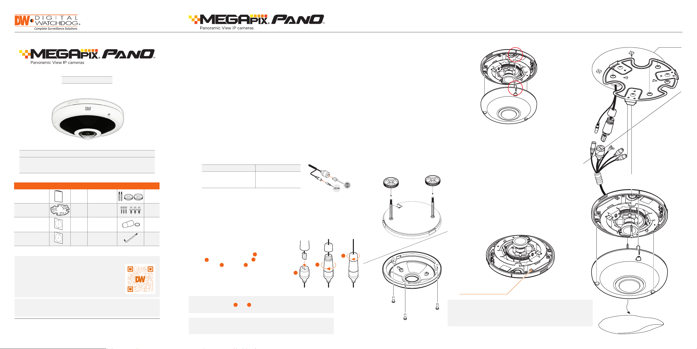
STEP 1 – PREPARING TO MOUNT THE CAMERA
1. The mounting surface must bear five times the weight of your
camera.
2. Do not let the cables get caught in improper places or the electric line
4. Re-attach the camera’s gasket ring and dome to the
camera module by aligning the screw holes. Be sure
to align the wedge on the side of the camera with
the one on the mounting bracket.
Mounting template
cover to be damaged. This may cause a breakdown or fire.
3. Using the mounting template sheet or the camera itself, mark and drill
the necessary holes in the wall or ceiling.
Installation using mount bolt and screws:
1. Using the template sheet for the nuts and bolts
installation, mark and drill the holes on the mounting
STEP 2 – CABLING THE CAMERA TO
EXTERNAL DEVICES
Pass the wires through the mount bracket and make all necessary
connections.
a. NETWORK CONNECTIONS – If you are using a PoE switch,
connect the camera using an Ethernet cable for both data and
power.
b. NETWORK CONNECTIONS – If you are using a non-PoE switch,
connect the camera to the switch using an Ethernet cable for data
transmission and use a power adapter to power the camera.
surface.
2. Secure the two long mounting screws to the
camera’s base.
3. Pass the wires through the mount bracket and make
all necessary connections.
4. Mount the camera to the mounting surface by using
the 2 mounting nuts. Rotate the locking discs over
the screws until the camera is held tightly from the
mounting surface.
5. Re-attach the camera’s gasket ring and dome to the
camera module by aligning the screw holes. Be sure
to align the wedge on the side of the camera with
Power Requirements Power Consumption
DC12V, PoE IEEE 802. 3af
Class 3 (Adapter not
included)
DC12V: max 8.5W
PoE: max 10W
POWER
NETWORK
the one on the mounting bracket.
STEP 3 – INSTALLING THE CAMERA
1. Once all cables are connected, secure the camera to the mounting
surface using the included screws.
2. For soft installation surfaces, use the included metal mount plate. Fix
the mounting plate on the mounting surface using the
included screws. Then, press the bottom case onto
1
the mounting plate. The three bezels on the case will
align and snap lock onto the plate.
3. To use the camera’s waterproof wiring:
(1). Install the LAN cable into .
(2). will be assembled to with a 1/4 turn.
b
(3). Thread tightly to .
c
a
a
b
a
NOTE: To ensure moisture seal, make sure the o-ring is in place
a
between and . In extreme environments use of an
b
outdoor rated sealer is recommended.
NOTE: When using the waterproof cap, crimp the RJ45
connector after passing the cable through the
waterproof cap.
c
b
Reset Button
Resetting the camera: To reset the camera, use the tip of a
paper clip or a pencil and press the reset button. Pressing the
button for five (5) seconds will initiate a camera-wide reset of
all the settings, including network settings.
Page 2
Quick Start Guide
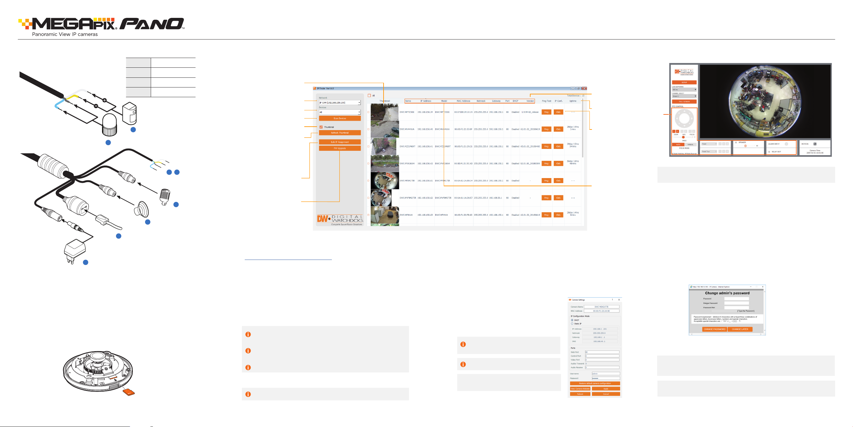
STEP 4 – CABLING
1
Power
DI (+)
DI (-)
DO (-)
DO (+)
6
Alarm input
5
Alarm output
2
Network
WHITE
YELLOW
SKY BLUE
GRAY + DOT
4~5
out
4
3
Audio output
Alarm in/
Audio input
STEP 5 – MANAGING THE SD CARD
To install the memory card:
1. The SD card slot is located next to the reset button.
2. Detach the camera’s cover dome from the camera’s module by
unscrewing the cover dome screws.
3. Insert a Micro SD/SDHC class 10 card according to the diagram.
4. To remove the SD card, press the card gently into the card slot to
release it. The card will pop out automatically.
STEP 6 – DW IP FINDER
™
Use the DW IP Finder™ software to scan the network and detect all MEGApix® cameras, set the camera’s network settings or access the camera’s web client.
Thumbnail view
Select network to scan
Filter device type to scan
Firmware version
Camera’s uptime
Scan devices
Show/hide thumbnail view
Refresh thumbnail view
Open Device
configuration
settings
Bulk IP assignment
Device’s
information
Firmware upgrade
Network Setup
1. To install the DW IP Finder™, go to:
http://www.digital-watchdog.com
2. Enter “DW IP Finder” on the search box at the top of the page
and press Enter.
3. Click on the DW IP Finder from the search result and go to the
Software tab. Click on the download icon to download the DW
IP Finder installation file.
4. Run the installation file and follow the wizard to install the DW
IP Finder™. Open the DW IP Finder™ and click ‘Scan Devices’. It
will scan the selected network for all supported devices and list
the results in the table. During the scan, the DW logo will
turn g ray.
Selec t DHCP if the internet service is dynamic IP. This will allow the
camera to receive its IP address from the DHCP server.
Selec t “Static” to manually enter the camera’s IP address, (Sub)
Netmask, Gateway and DNS information.
* The camera’s IP must be set to Static if connecting to
DW Spectrum
Contact your network administrator for more information.
Default TCP/IP information: DHCP
5. Select a camera from the list by double-clicking on the
camera’s image or click on the ‘Click’ button under the IP Conf.
column. The pop-up window will show the camera’s current
network settings, allowing admin users to adjust the settings as
needed.
6. To access the camera’s web page, click on ‘View
Camera Website’.
7. To save the changes made to the
camera’s setting, input the username
and password of the camera and click
Apply. Click “Scan Devices” from the
main screen again to display the
updated information.
‘Port forwarding’ has to be set in your
network’s router for external access
to the camera.
Default ID / PW : admin / admin
*NOTE: For security purposes, it is highly
recommended to change your
password after initial setup.
STEP 7 – WEB VIEWER
*
The GU I display may di er by camera models .
* NOTE: Some menu options may not be available based on the
camera model. See the full manual for more information.
Once the camera’s network settings have been setup properly, you can
access the camera’s web viewer using the DW® IP Finder™.
To open the camera’s web viewer:
1. Find the camera using the DW® IP Finder™.
2. Double-click on the camera’s view in the results table.
3. Press the ‘View Camera Website’. The camera’s web viewer will
open up in your default web browser.
4. Enter the camera’s username and password you setup in the DW®
IP Finder™. If you did not setup a new username and password via
the DW® IP Finder™, you will not be able to view video from the
camera. A message will direct you to setup a new password for the
camera in order to view video.
5. When accessing the camera for the first time, install the VLC player
for web files in order to view video from the camera.
NOTE: 32bit version of VLC player must to be installed. If you are
using 64bit system, uninstall the previous 64bit version and
reinstall using the 32bit version.
NOTE: Please see the full product manual for web viewer setup,
functions and camera settings options.
Rev Date: 0 4/20
Speci fications an d pricing are subjec t to change with out notice.
Copyright © Digital Watchdog. All rights reserved.
 Loading...