

Page 1
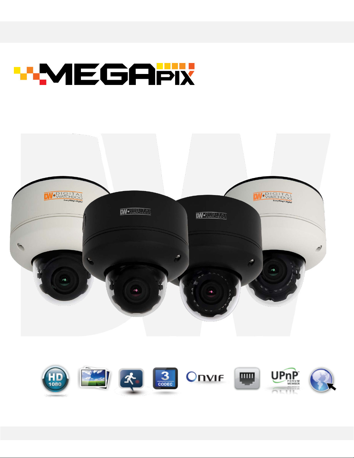
DWC-MV421D, DWC-MV421DB
DWC-MV421TIR, DWC-MV421TIRB
MEGApix 1080p Snapit™ Outdoor Dome IP Camera
Before installing or operating the camera, please read and follow this manual carefully.
Rev.:09/10
Page 2

PRECAUTIONS
Do not open or modify.
Do not open the case except during maintenance and installation, for it may be dangerous and
can cause damages.
Do not put objects into the unit.
Keep metal objects and flammable substances from entering the camera. It can cause fire, short-
circuits, or other damages.
Be careful when handling the unit.
To prevent damages, do not drop the camera or subject it to shock or vibration.
Do not install near electric or magnetic fields.
Protect from humidity and dust.
Protect from high temperature.
Be careful when installing near the ceiling of a kitchen or a boiler room, as the temperature may
rise to high levels.
Cleaning: To remove dirt from the case, moisten a soft cloth with a soft detergent solution and
wipe.
Mounting Surface: The material of the mounting surface must be strong enough to support the
camera.
FCC COMPLIANCE
This equipment has been tested and found to comply with the limits for a Class B digital device,
pursuant to Part 15 of the FCC rules. These limits are designed to provide reasonable protection
against harmful interference, when the equipment is operated in a residential environment. This
equipment generates, uses, and radiates radio frequency energy, and if it is not installed and used in
accordance with the instruction manual, it may cause harmful interference to radio communications.
WARNING: Changes or modifications are not expressly approved by the manufacturer.
2
Page 3

TABLE OF CONTENT*
Introduction ......................................................................................4
Features ....................................................................................................4
Inside the Box ...........................................................................................5
Parts .........................................................................................................6
Camera Control Board ...............................................................................7
Dimensions ...............................................................................................8
Installation ........................................................................................9
Network Connection ..................................................................................9
Installation ..........................................................................................10- 12
SD Card Installation .................................................................................13
Cabling ....................................................................................................14
Adjusting the 3 - Axis Gimbal......................................................................15
MEGAPIX Camera Setup .....................................................................16
Installing DW IP Finder .............................................................................16
Using DW IP Finder .............................................................................17- 18
Network Options ......................................................................................19
Camera Reboot ........................................................................................20
MEGAPIX Camera Web Viewer ............................................................21
Accessing the Web Viewer ..................................................................21- 22
First & Second Stream .............................................................................23
Export Image ...........................................................................................24
Print Image .............................................................................................25
Panic Recording .................................................................................26- 27
MEGAPIX Camera Setup ....................................................................28
Video & Audio ....................................................................................28- 33
Event ..................................................................................................34- 37
Network ..............................................................................................38- 43
Record & Remote Backup ....................................................................44- 47
System ...............................................................................................48- 54
Specifications .............................................................................55- 56
Troubleshooting ..........................................................................57- 60
Warranty ..........................................................................................61
Limits & Exclusions ...........................................................................62
3
Page 4

FEATURES*
2.1 Megapixel Image Sensor (1080p, 30fps)
Wide Dynamic Range (WDR)
Triple Codecs (H.264, MJPEG, MPEG4) with Simultaneous Dual- Stream
2.8~12mm Auto Focus P- Iris Lens
CleanView™ Hydrophobic Dome Coating Repels Water, Dust and Grease
Snapit™ Easy Installation Housing
Smart IR™ with Intelligent Camera Sync. 70ft Range (IR Models)
True Day/Night with Mechanical IR Cut Filter (IR Models)
Manual IR Activation (IR Models)
Smart DNR™ 3D Digital Noise Reduction
Auto Gain Control (AGC)
Backlight Compensation (BLC)
Auto White Balance (AWB)
Programmable Privacy Zones
Motion Detection
Micro SD/SDHC Class 10 Card Slot for Emergency Backup [card not
included]
Junction Box Built- in
Alarm Sensor Input
Relay Output
Web Server Built- in
PoE and DC12V
Black Housing Option
ONVIF Conformant, Profile S
IP68 Certified (Water Resistant)
4
Page 5
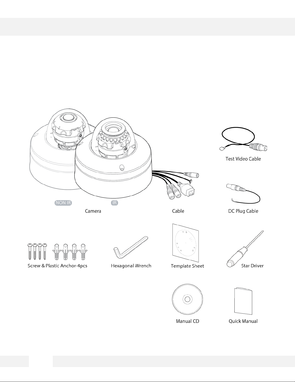
INSIDE THE BOX*
5
Page 6
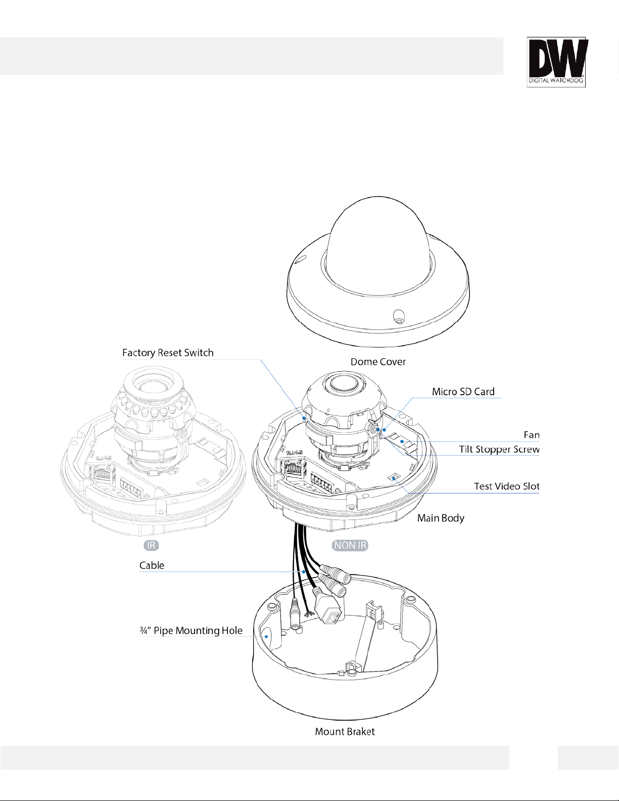
PARTS & DESCRIPTIONS*
6
Page 7
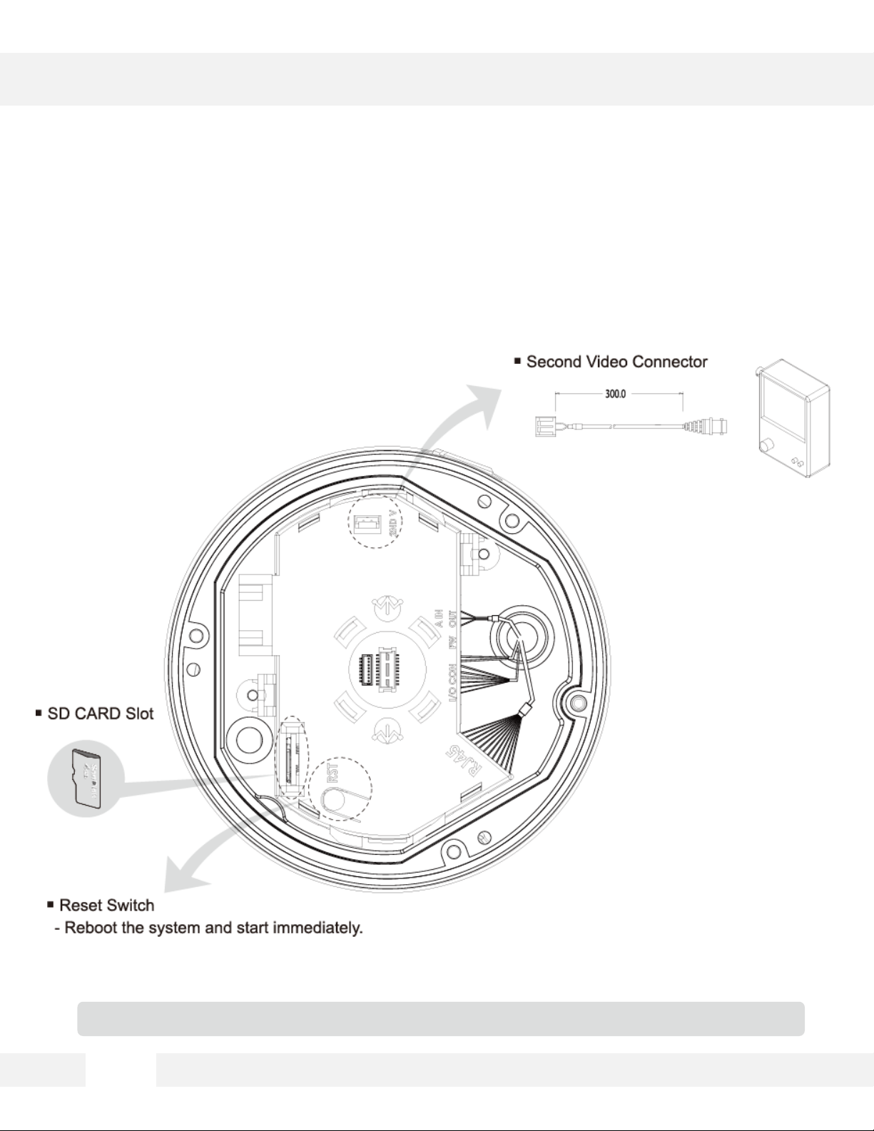
CAMERA CONTROL BOARD*
UART +/- is for debugging purposes only.
7
Page 8
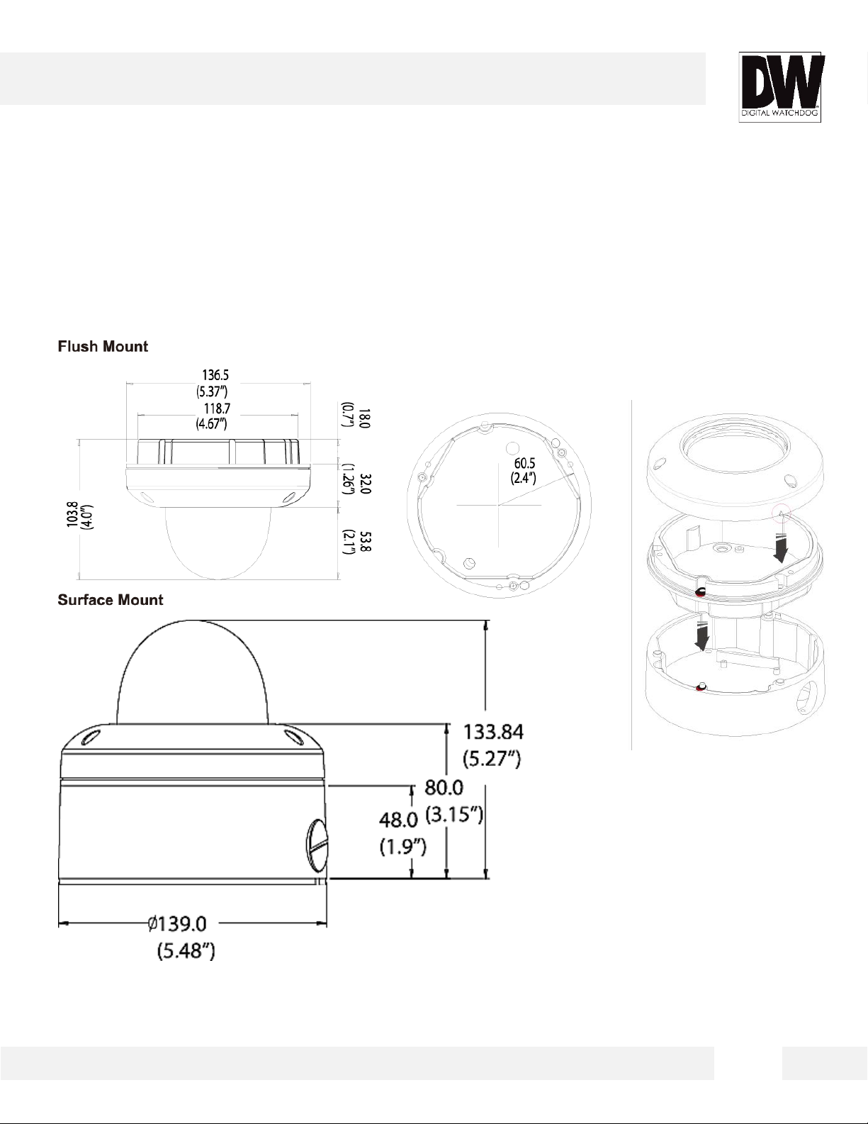
DIMENSIONS*
8
Page 9
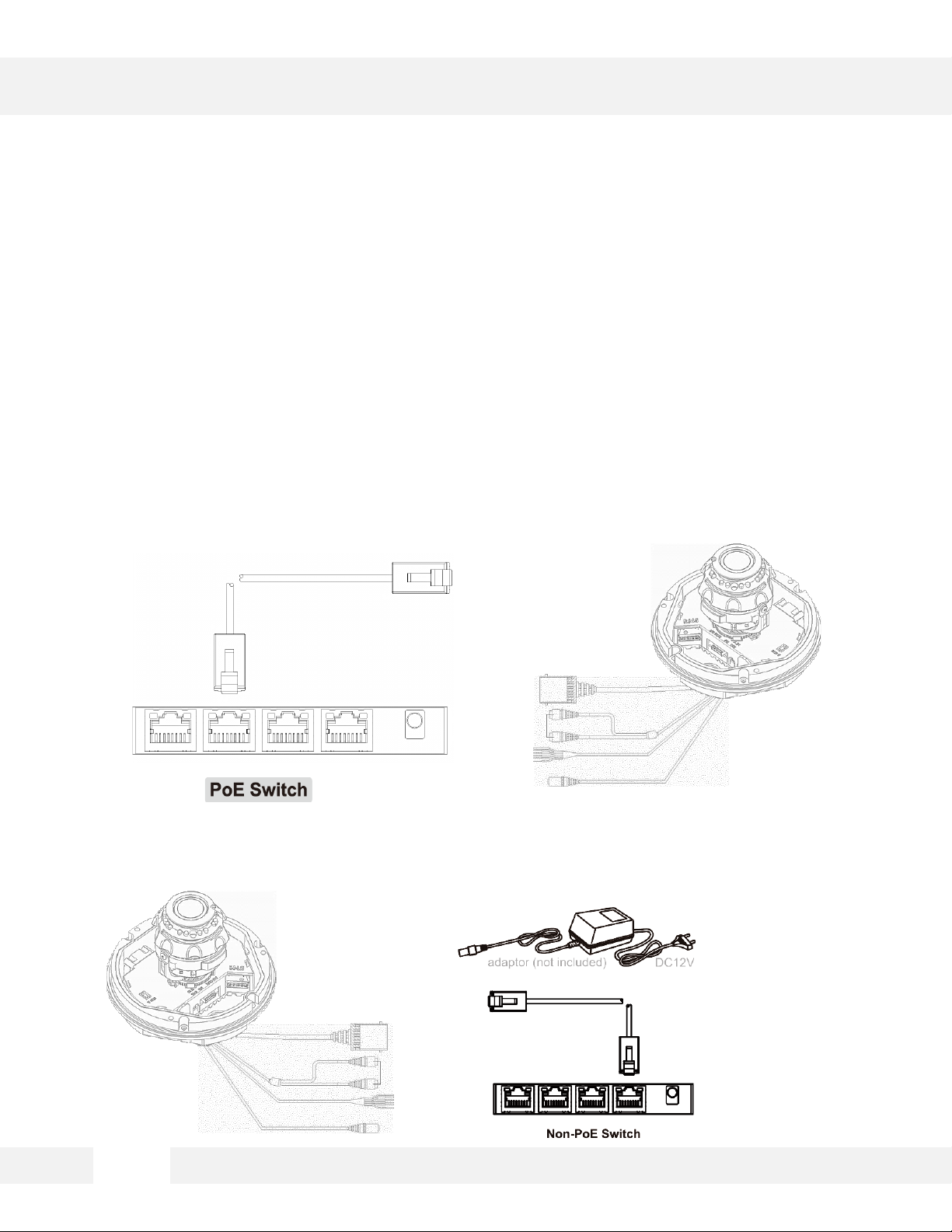
NETWORK CONNECTION*
There are two way to power a MEGApix® 1080p™ camera.
Use a PoE- enabled switch to connect data and power through a single
cable and begin viewing and recording images instantly. A non- PoE switch
will require an adaptor for power transmission.
1. Using a PoE-Enabled Switch
The MEGApix® 1080p™ Camera is PoE-Compliant, allowing transmission of power and data via a
single Ethernet cable. PoE eliminates the need for the different cables used to power, record, or
control the camera. Follow the illustration below to connect the camera to a PoE-enabled switch
using an Ethernet cable.
2. Using 12VDC
If a PoE injector is not available, use a power adaptor for power transmission and a non-PoE switch
for data transmission. Follow the illustrations below to connect the camera without a PoE Injector.
9
Page 10
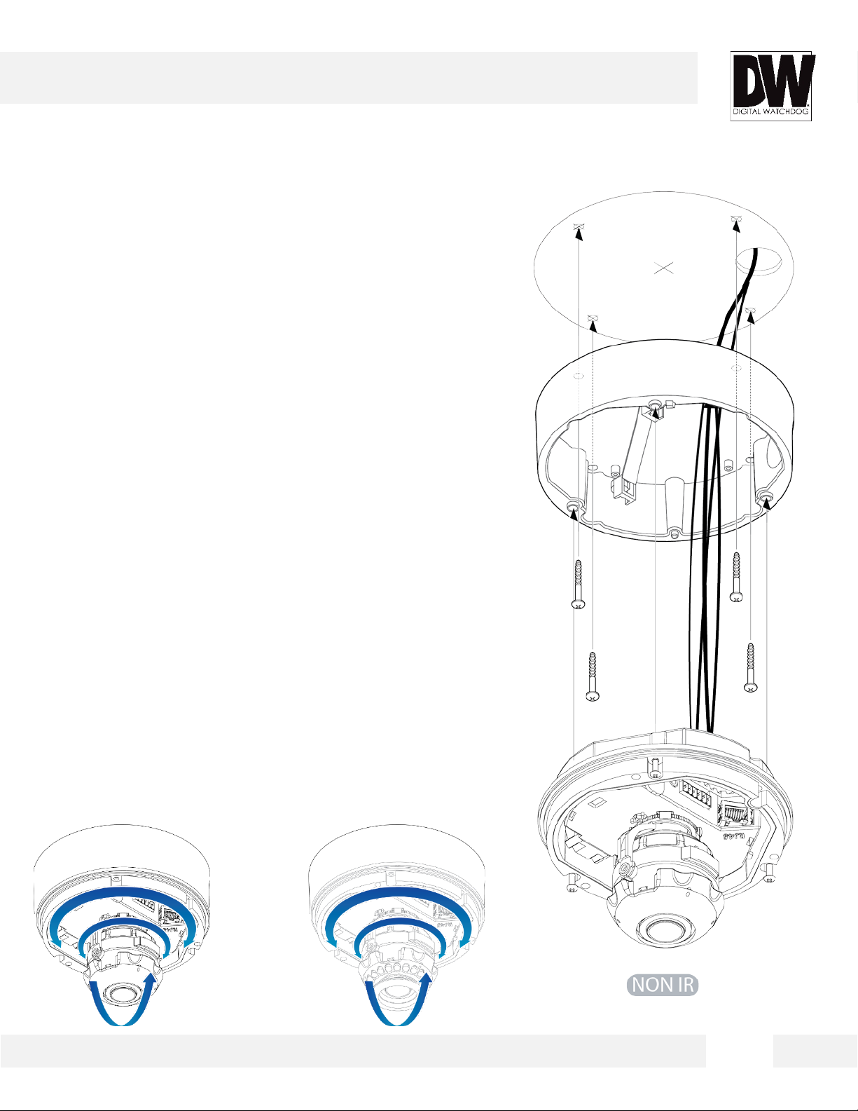
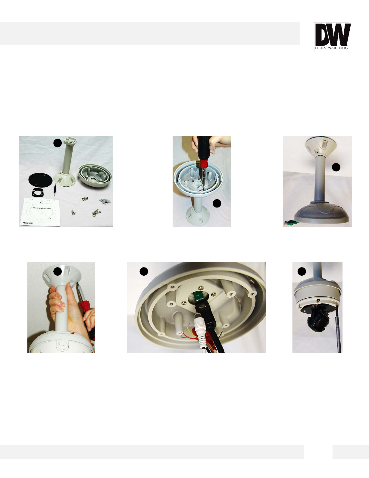
INSTALLATION*
Snapit Easy Installation
1. For the installation process, remove the
junction box from the camera module. To
remove the camera dome, loosen the three (3)
screws on the dome using the wrench
provided with the camera.
2. Use the camera’s mounting template or your
camera’s junction box to mark the holes as
required.
3. Drill holes into the mounting surface and
insert the drywall mounts into the holes.
4. Pull wires through and make connections. See
page 14 for more information
5. Secure the Camera module to the junction box
using three (3) screws.
6. Check the LED light.
Green light flickers for booting.
Red light turns on when booting is complete.
7. Adjust the camera’s tilt and lens position See
page 15 for more information.
8. Assemble the dome cover over the camera
body and detach the protecting film from the
dome bubble.
10
Page 11
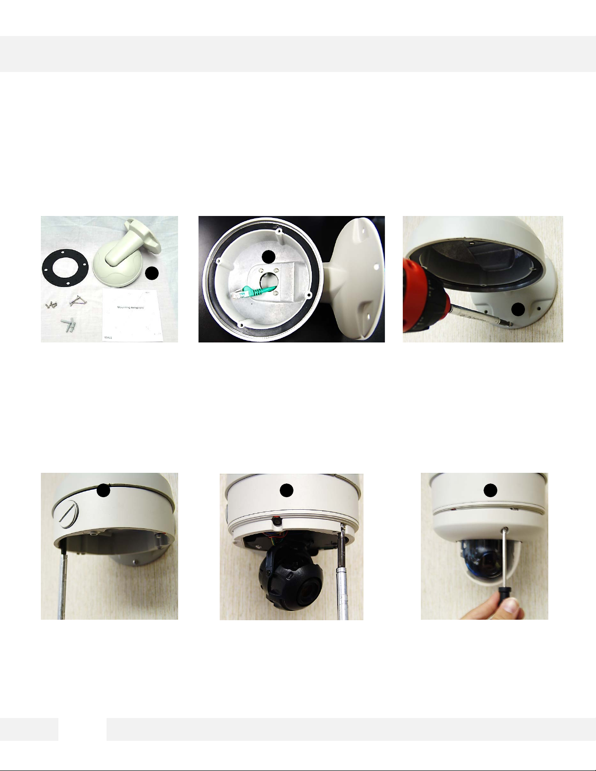
INSTALLATION*
Wall Mount for V4 Housing
1
2
3
1. Verify all parts are in
the box.
4 5 6
4. Attach the camera’s
Surface Mount Plate to
the Wall Mount.
2. Run cables into the
mount.
5. Connect all cables and
snap the camera
module onto the base.
3. Use the mounting template to
make pilot holes. Use the dry
wall anchors and wood screws
to attach the assembly to the
wall.
6. Adjust the camera and
secure the cover dome
over the camera
module.
11
Page 12
INSTALLATION*
Ceiling Mount for V4 Housing
1
3
2
1. Verify all parts are in
the box.
4
4. Use the mounting
template to make pilot
holes. Use the dry wall
anchors and wood
screws to attach the
assembly to the wall.
2. Attach the top shield to
the pendant mount.
5. Connect all cables and
verify camera is
operating properly.
3. Run all necessary
cables from the
ceiling to the mount.
65
6. Attach the camera to
the ceiling mount
and secure the cover
dome properly.
12
Page 13
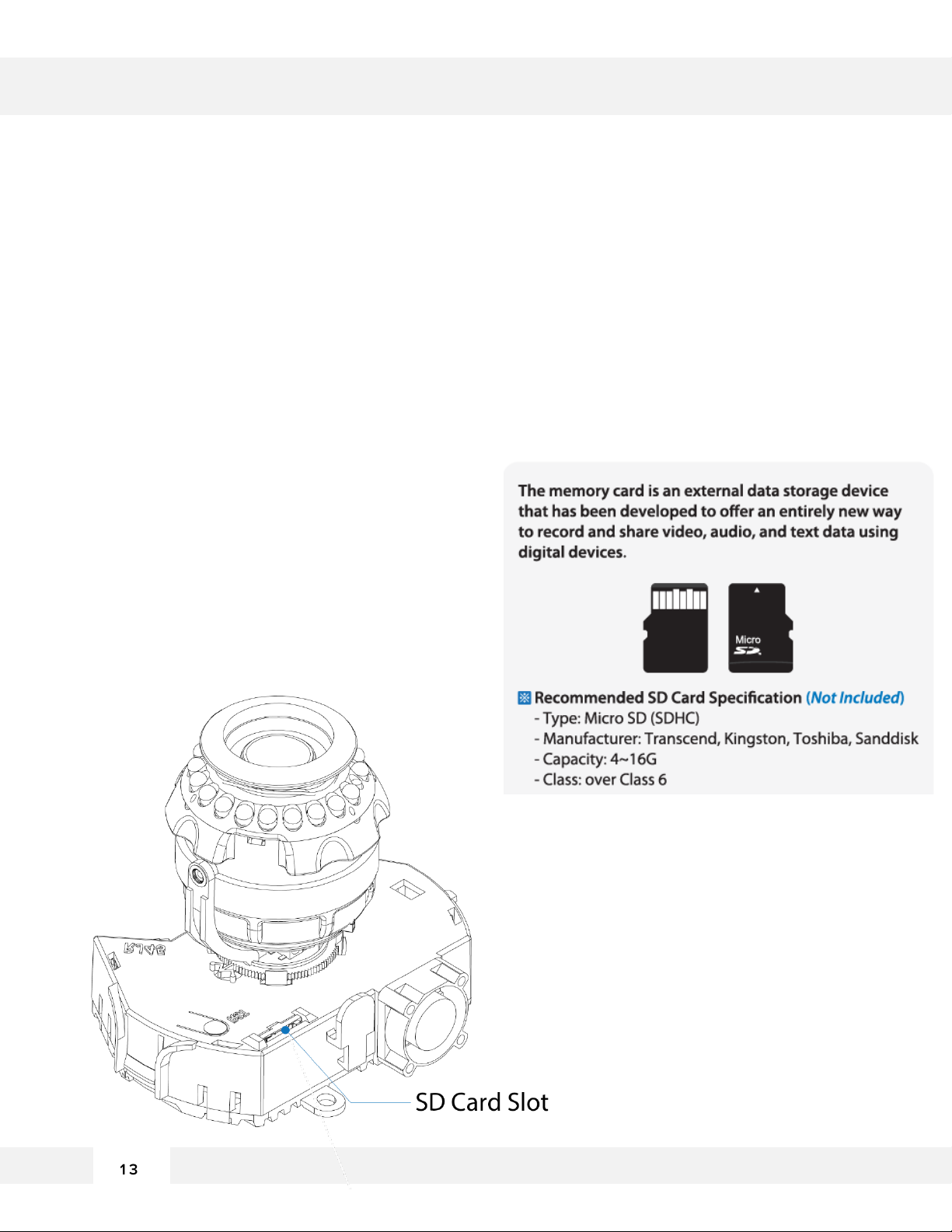
INSTALLATION*
SD Card
Use the diagram below for installation of 15an SD Card for local emergency
backup. When setup properly, the camera will record to the local SD card
when it detects it is not recording to any servers and is not connected to
the network.
To install the SD card:
1. Locate the SD card slot in the back of the camera
module.
2. Insert the SD card in the slot and push it down, until
you hear a ‘click’ sound.
3. To remove SD card, press the SD card down until
you hear a ‘click.’ The SD card will eject from the slot.
4. When you are complete, go to the camera’s web
viewer. (See page xx for more information)
13
Page 14
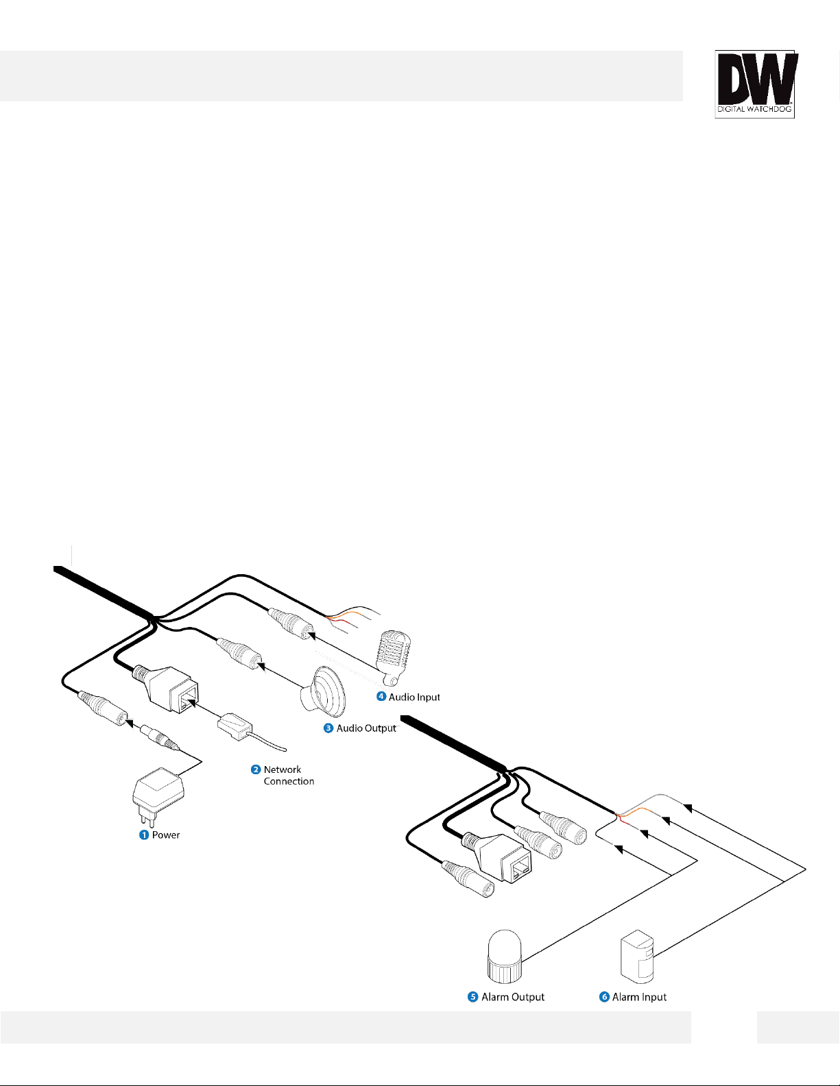
INSTALLATION*
Cabling
Use the diagram below to connect all external devices such
as alarms, sensors, and audio, to the camera.
1. Network Connection: Connect the camera to your network using an RJ59 cable.
2. Audio Input: Connect the camera to an audio input source such a microphone.
3. Audio Output: Connect the camera to an audio output such as speakers.
4. Alarm Input: Connect the camera to an alarm input source such as a sensor.
5. Alarm Output: Connect the camera to an alarm output source such as an alarm, door lock, etc.
6. Power: If PoE switch is not available (See page 9), use DV12V power supply to power the camera.
14
Page 15
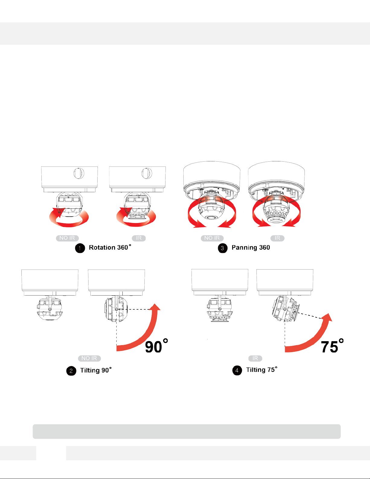
CAMERA’S ANGLE*
The Gimbal mechanism yields maximum rotation and
placement as shown below.
Do not over rotate the lens. Doing so will damage the camera lens module.
15
Page 16
DW DESKTOP TOOL™
Installing DW IP Finder™ Software
DW Desktop Tool™ searches for all available Digital Watchdog devices
currently connected to your network.
1. Install DW Desktop Tool to find the MEGApix® 1080p™ camera on your local network. The
software can be found on the included User Manual CD. Run DW Desktop Tool and install onto
your PC.
2. When setup is complete, launch DW Desktop Tool.
3. The software will automatically search your network for all Digital Watchdog® supported devices.
Your camera will appear as ”DWC-MD421D”, “DWC-MD421DB”, “DWC-MD421TIR”, “DWC-
MD421TIRB”.
4. Double-click on the camera name and select ‘View Camera Website’ to launch the camera’ web
viewer.
*Install the DW Desktop Tool to a computer on the same Subnet Mask as the MEGApix® camera.
16
Page 17
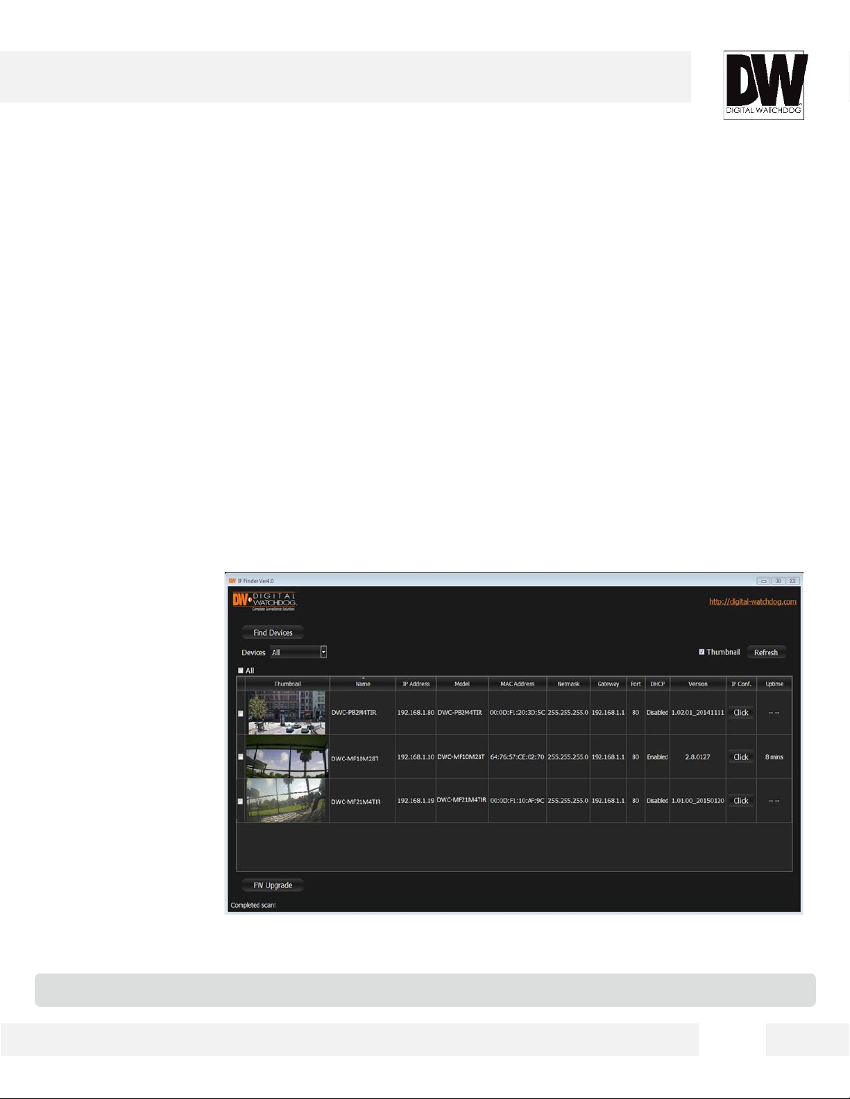
DW IP FINDER™
Using DW IP Finder™ Software
Use DW Desktop Tool™ to change the basic settings of your MEGApix®
camera or to connect to your MEGApix® camera.
17
Page 18
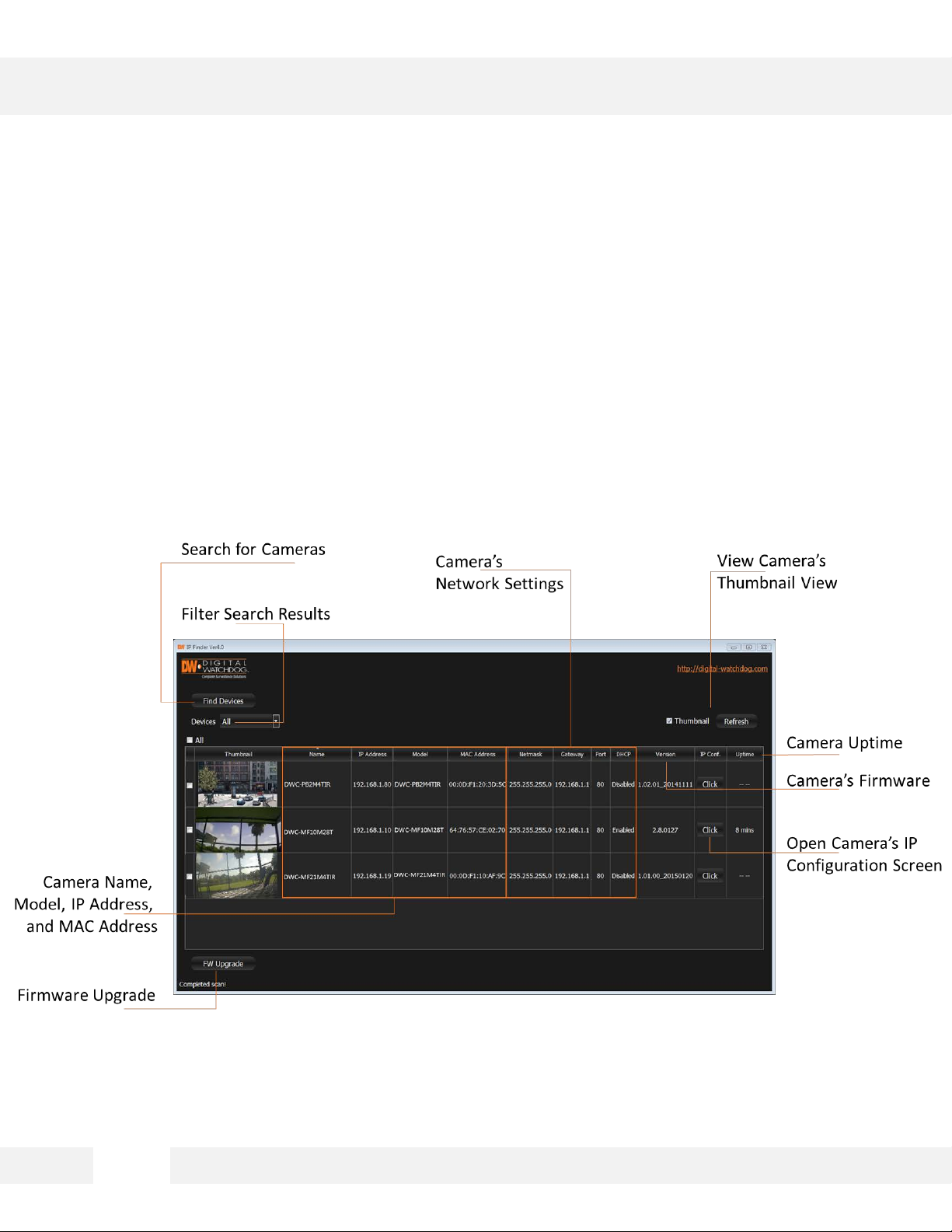
DW IP FINDER™
Using DW IP Finder™ Software
Use IP Finder to set the connection type and the IP address information
for your MEGApix® 1080p™ camera.
1. DHCP: Select DHCP to access the camera within the same internal network. For further
explanation on DHCP, please see page 15.
2. Static IP: Select Static to connect to the camera from an external network. For further
explanation on Static, please see page 15.
*If you change the camera’s IP, write down the camera’s MAC Address for identification in the future.
18
Page 19

DW IP FINDER™
DHCP
The Dynamic Host Configuration Protocol (DHCP) is a network configuration protocol that allows
a device to configure automatically according to the network it is connected to. If your network
supports DHCP, and your MEGAPIX camera is setup as DHCP; then once you search for your
camera using IP Finder, the search results will display your MEGAPIX camera with already set
network settings that correspond to your network requirements.
Static
Static IP addresses are recommended when using a network that does not support DHCP. If Static is
selected, then you must manually enter all the network settings for your MEGAPIX camera that would
correspond with your network. Static IP addresses are recommended if you want to setup your device
to be accessed externally via the internet. For each setup of the camera to a static IP address, it is
recommended that you first setup the camera to DHCP, allow it to configure itself according to your
network, and then change the settings to a static IP address. To set your MEGAPIX camera to static,
highlight the desired device from the search results list, and click on Configuration. In the new setup
window, make sure static is selected. Enter the following information: IP Address, Netmask, Gateway,
Preferred DNS. Click Apply and System Reboot to save all changes.
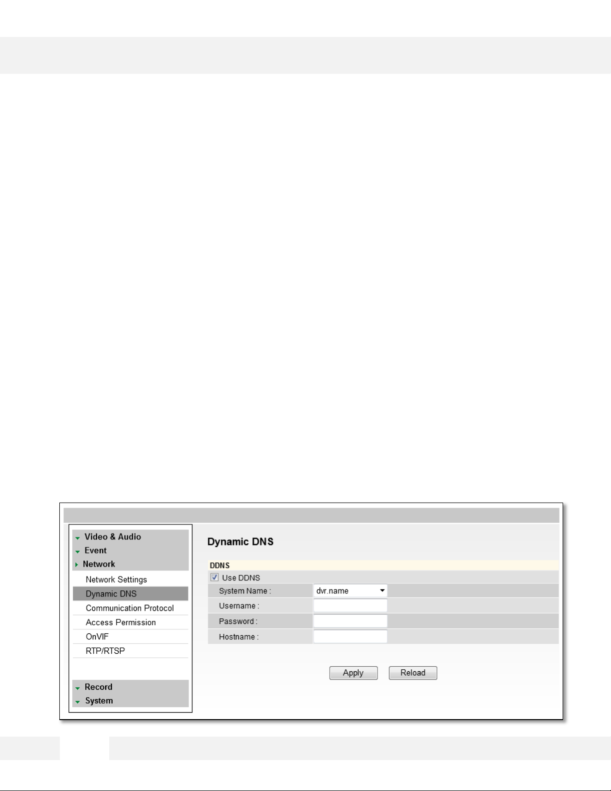
DDNS
Dynamic Domain Server is a feature that allows you to use a URL instead of an IP address to access
your MEGAPIX camera. The feature is optional, for it may require subscription and payment. To use the
DDNS feature, check the box next to Use DDNS. Select the server you wish to use. *Some servers may
require subscription and payment. Enter the desired Hostname. If applicable, enter the User ID and
Password. Click Apply and System Reboot to save all changes.
19
Page 20
CAMERA REBOOT*
Resetting the Camera
Pressing the reset button on the camera’s control board for five (5) seconds will initialize all
environmental variables to factory default. Previous setup for IP default, time, etc. will be deleted. If a
system’s IP address is lost, reset the camera back to factory default.
The following are the default network settings.
IP Mode DHCP
IP Address 192.168.1.123
Subnet Mask 255.255.255.0
Gateway 192.168.1.123
Base Port 7000
HTTP Port 80
*Frequent use may cause system error.
20
Page 21
WEBVIEWER*
Remote Video Monitoring Via Internet Explorer
Monitor and configure the MEGAPIX camera through a builtin Web viewer.
1. Type the IP address of the camera on the Internet Explorer window.
Example: http://192.168.1.123 (Factory Default)
2. Enter Username and Password. Username: admin | Password: admin
3. The web browser will ask to install Active-X Control. Once it has been installed, Internet Explorer will
display video images from the camera.
21
Page 22

WEBVIEWER*
Remote Video Monitoring Via Chrome, Firefox, or Safari
Yo u can view your MEGAPIX camera using web browsers
other than Internet Explorer. To do so, at least one of the
streams of the camera must be set to the codec MJPEG.
1. Open Google Chrome, Mozilla Firefox, or Apple Safari Web Browser.
2. Enter the IP camera’s IP address. NOTE: If the first stream is set to H.264, then a video will not be
displayed on the GUI.
3. Click the Setup button. Then go to Video & Audio > Stream Settings.
4. Modify one of the two streams to the codec MJPEG.
5. Click Apply to make sure all changes have been saved and your camera has been rebooted.
6. Exit the screen to return to the camera’s main page.
7. At the bottom of the page, select the stream you set as MJPEG. The camera will start streaming
video.
22
Page 23

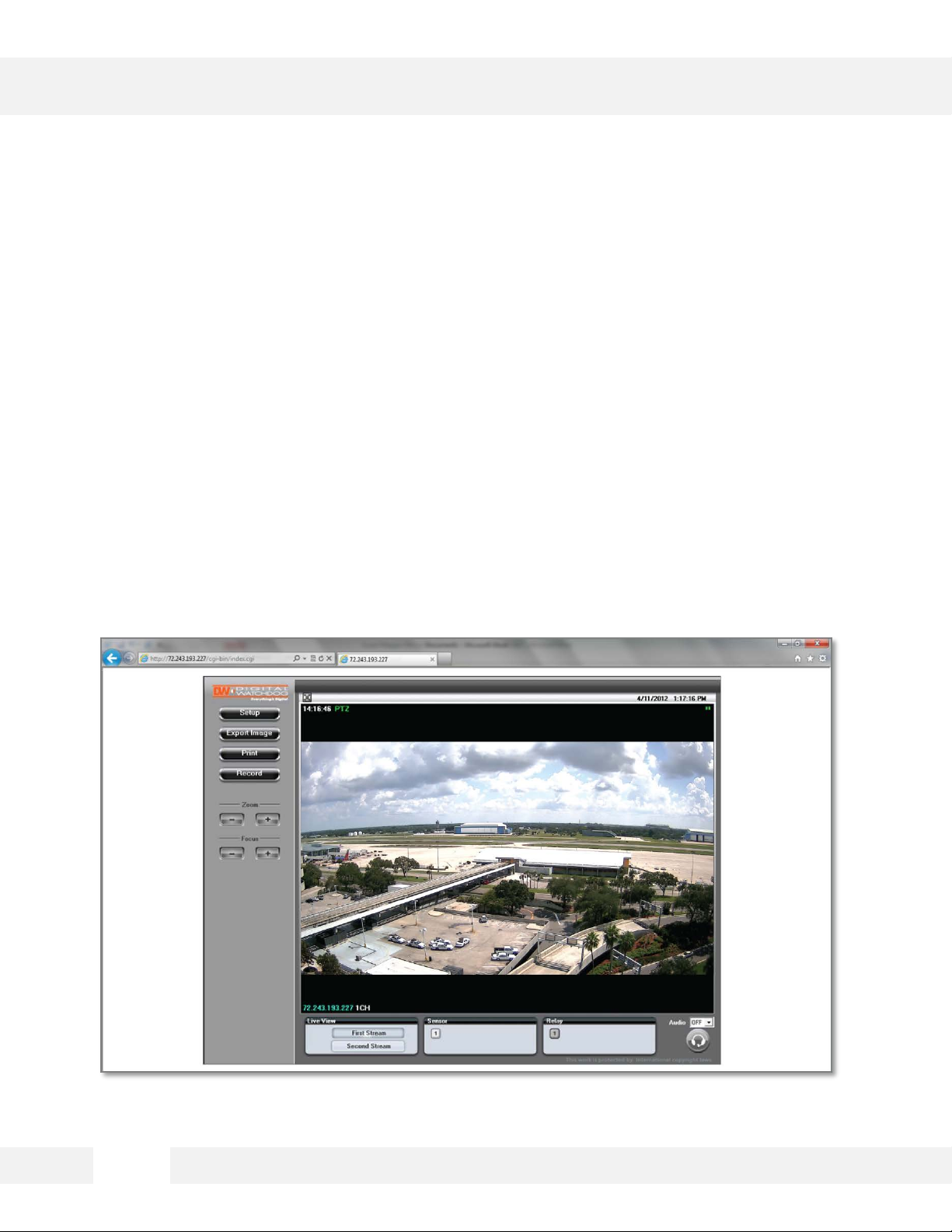
WEBVIEWER*
Display Screen > First Stream & Second Stream
Configure two stream settings for monitoring and recording.
On the main monitoring page, view the camera with the First Stream settings or the Second Stream
settings.
Below the display screen, click on the First Stream and Second Stream buttons to view the different
camera settings.
To setup Stream Settings, refer to page xx.
23
Page 24

WEBVIEWER*
Display Screen > Export Image
Export a screenshot of current live video to your computer.
1. Select the Export Image button. A ‘Save As’ window will appear.
2. Select the folder you wish to Save in and type a File Name.
3. Click ‘Save’ and the screenshot will be saved.*
1
*By default, image can only be saved as a JPEG file.
2
3
24
Page 25

WEBVIEWER*
Display Screen > Print Image
Print a screenshot of the current live video.
1. Select the Print button. The Print Preview window will appear.
2. Adjust the orientation of the screenshot: portrait or landscape, facing left, right, up, or down.
3. Zoom in on a portion of an image prior to printing or select the image’s scale on the page:
4. To print information about the screenshot, select View Title.
5. To add a memo for the screenshot, select Page Option.
6. Go to Printer Setup to select the printer and manage printer properties.
7. Select Print to print the page, or Close to cancel the print.
5
1
3
2
7
4
6
25
Page 26
WEBVIEWER*
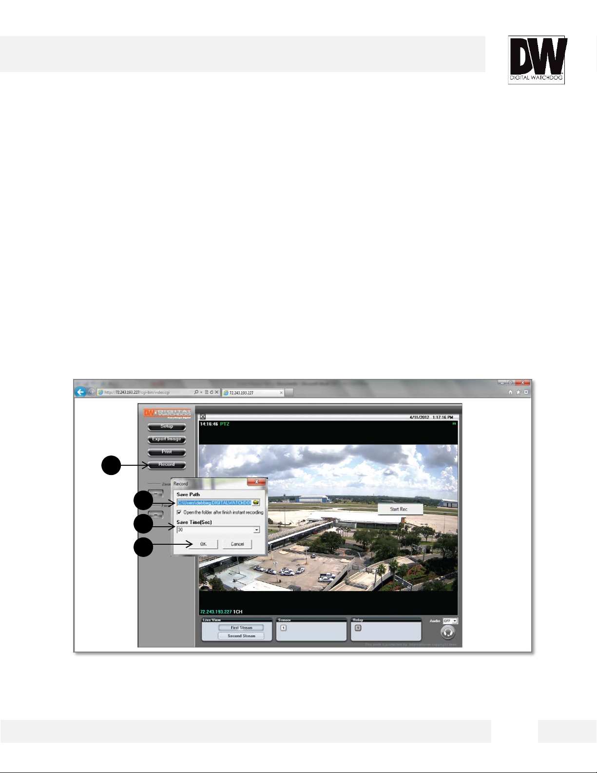
Display Screen > Record
Instantly record live video to your local drive.
To Setup Instant Recording
1. Select the Record button.
2. Indicate where you want the videos to be saved.
3. Setup the duration of the instant recording. You can record up to 120 seconds of live video.
4. When setup is complete, click OK to save changes or Cancel to cancel any changes.
1
2
3
4
26
Page 27
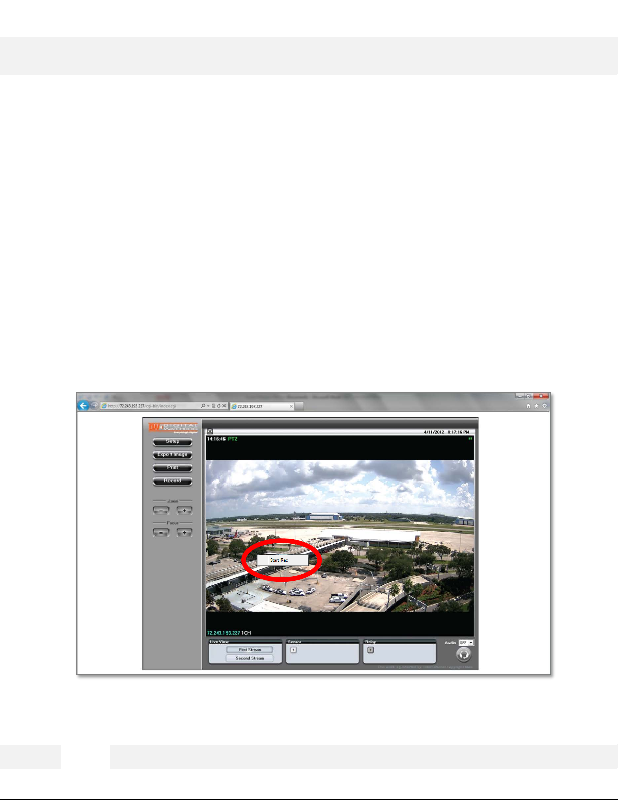
WEBVIEWER*
Display Screen > Record
Instantly record live video to your local drive.
To Start and Stop Instant Recording:
1. To Start, right-click anywhere on the display screen.
2. Select Start Rec. The icon on the top right of the screen will change to INSTANT.
3. To Stop, right-click anywhere on the display screen.
4. Select Stop Rec. The video will be displayed in the designated folder when recording is complete.
27
Page 28

WEBVIEWER*
Setup > Video & Audio > Stream Settings
The Recommended Stream Settings are indicated on the
image to the left. This is also the factory default settings.
1. Name: Set a distinguished name to each stream to identify each.
2. Resolution: Set Resolution for each stream. The better the resolution of the video, the more
bandwidth it will require to stream images.
3. Compression Type (Codec): Select the type of compression to use when outputting the video.
4. Data Transfer Speed: Set encoding bitrate if H.264 and MPEG4 compression type is selected.
5. Framerate: Select from 0fps to 30fps.
6. MJPEG Quality: Set MJPEG image quality. This is only available when the compression is set to
MJPEG. The higher the quality, the more bandwidth will be required to stream the image.
7. Select Apply to save changes.
1
3
5
7
2
4
6
28
Page 29
WEBVIEWER*
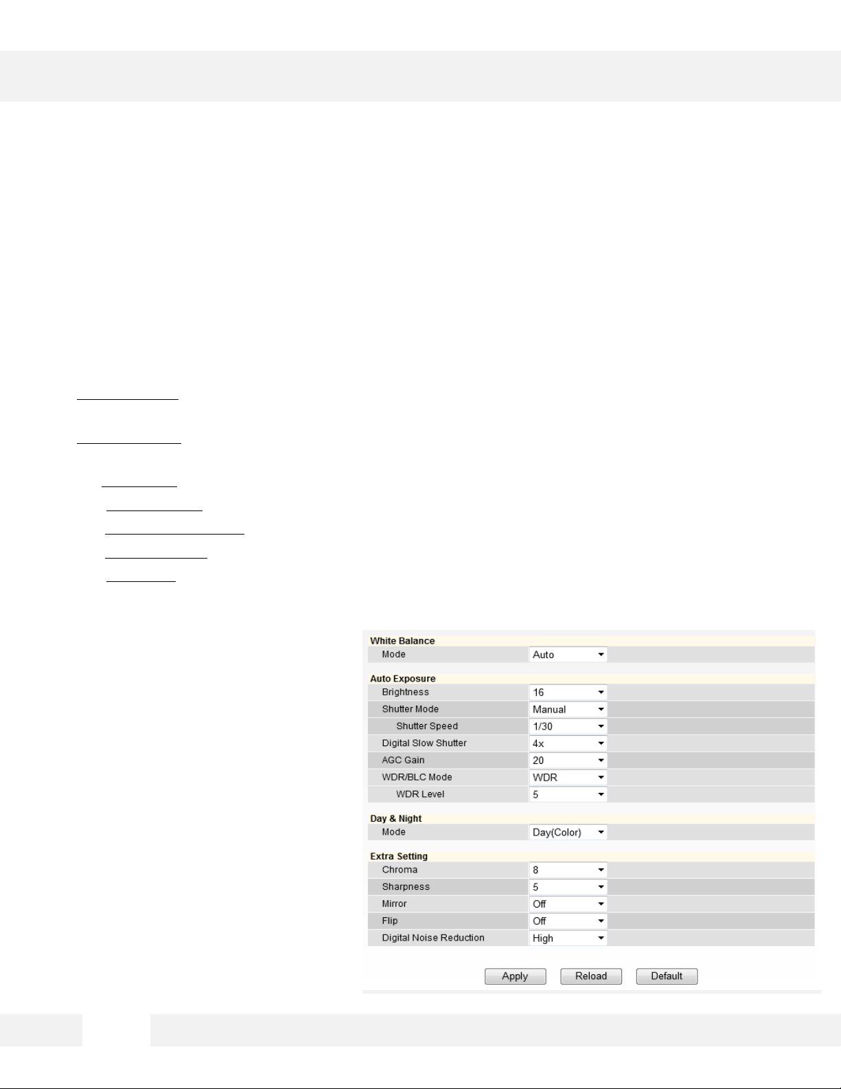
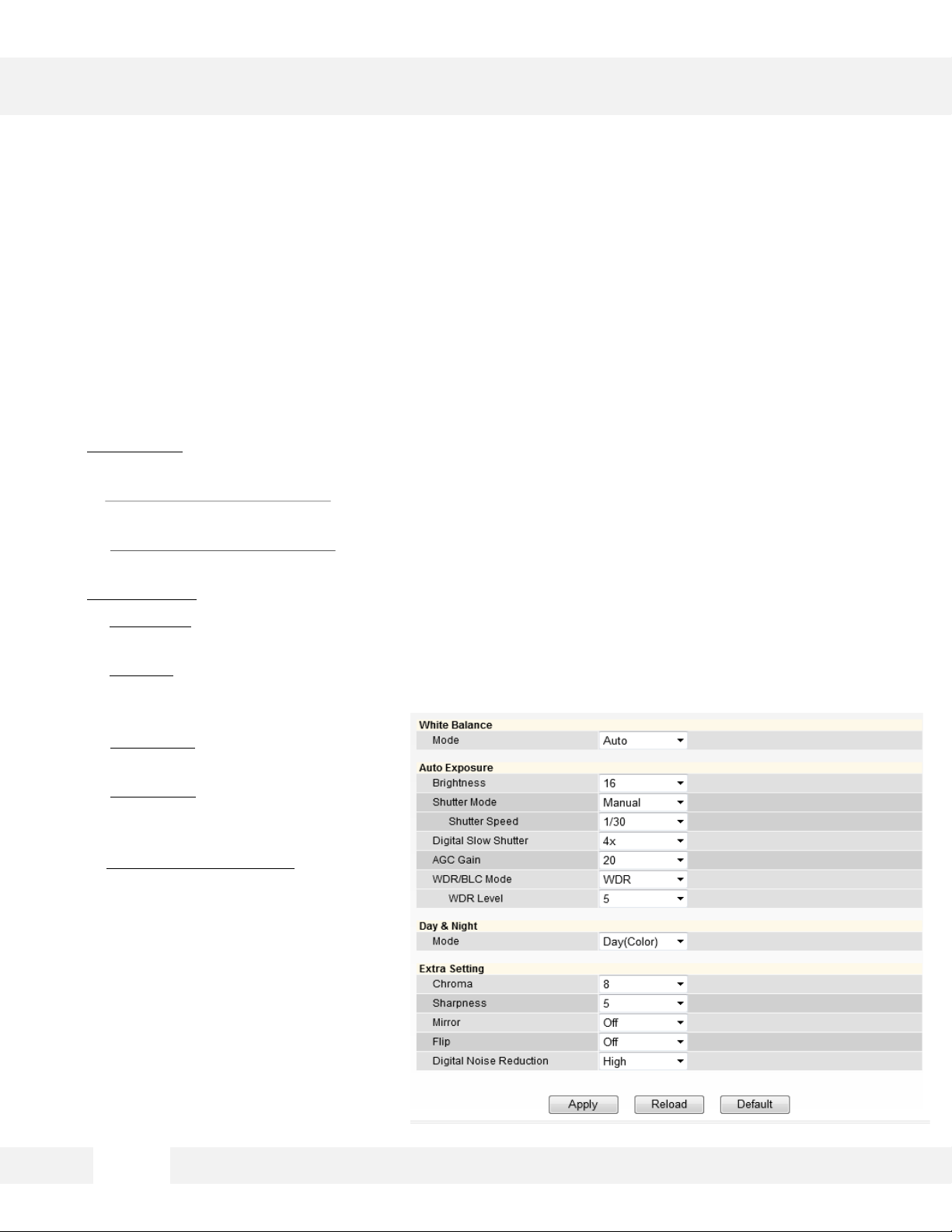
Setup > Video & Audio > Color Settings
Use this setup menu to adjust the camera’s White Balance,
Exposure, Day/Night and image settings.
• White Balance: Mode - Also known as Color Balance. This gives the camera a reference to “true
white.” Select from Auto, Auto_H, Auto_L, Preset, or Manual.
• Auto Exposure: Set Brightness, Shutter Mode, Digital Slow Shutter, Shutter Speed, AGC Gain, and
BLC Mode.
1. Brightness: Select from 0 (darkest) to 20 (brightest).
2. Shutter Mode: Set the amount of light allowed in the video manually or automatically.
3. Digital Slow Shutter: Recommended in low light conditions. Turn On (2x, 3x, 4x) or Off.
4. Shutter Speed: Select the speed at which the camera’s shutter will operate—1/30, 1/60, or 1/120.
5. AGC Gain: Maximum light gain settings in low light conditions. Select from 0 (least light) to 20
(most light).
29
Page 30

WEBVIEWER*
Setup > Video & Audio > Color Settings
Use this setup menu to adjust the camera’s White Balance,
Exposure, Day/Night and image settings.
• WDR/ BLC Mode: In this menu you can select to apply either Wide Dynamic Range or Backlight
Compensation to adjust the image in harsh lighting environments.
1. WDR Level: If WDR is selected, adjust the level of WDR between 0 (no WDR) to 9 (high WDR
adjustment). The default value is 5. The higher the WDR level, dark areas in the image will appear
brighter, and bright areas will appear darker.
2. Back Light Compensation (BLC): Adjust the camera’s capture of light when there is strong
backlight in the camera’s Field of View [FoV]. Select to enable or disable.
• Select ‘Apply’ to save changes, ‘Reload’ to return to the last saved settings, or ‘Default’ to return all
settings to their factory default values.
30
Page 31
WEBVIEWER*
Setup > Video & Audio > Color Settings
Use this setup menu to adjust the camera’s White Balance,
Exposure, Day/Night and image settings.
• Day & Night: Set the mode to Night (B/W), Day (Color), or Auto. If set as Auto, set a desired Color to
B/W Level and B/W to Color Level.
1. Switching from Color to B/W: Select from 0~10. The higher the number, the less darker
the environment will have to be for the camera to switch from color to B/W.
2. Switching from B/W to Color: This number should always be lower than the number set
to color to B/W.
• Extra Settings: Set Lens Type, Chroma, Sharpness, Mirror, Flip, and Digital Noise Reduction.
3. Lens Ty pe: Set the camera to an indoor or outdoor lighting environment. Select Manual,
DC, or AF.
4. Chroma: Affect the quality of the color in the image. Select from 0~20. The higher the
number, the brighter the color in
the video.
5. Sharpness: Select sharpness from
0~10 of the image.
6. Mirror/ Flip: Select On or Off to
mirror the image from left to right,
or flip it upside down.
7. Digital Noise Reduction: Control the
level of noise in the image. Select from
Off, Low, Middle, or High.
8. Select Apply to save changes.
31
Page 32
WEBVIEWER*
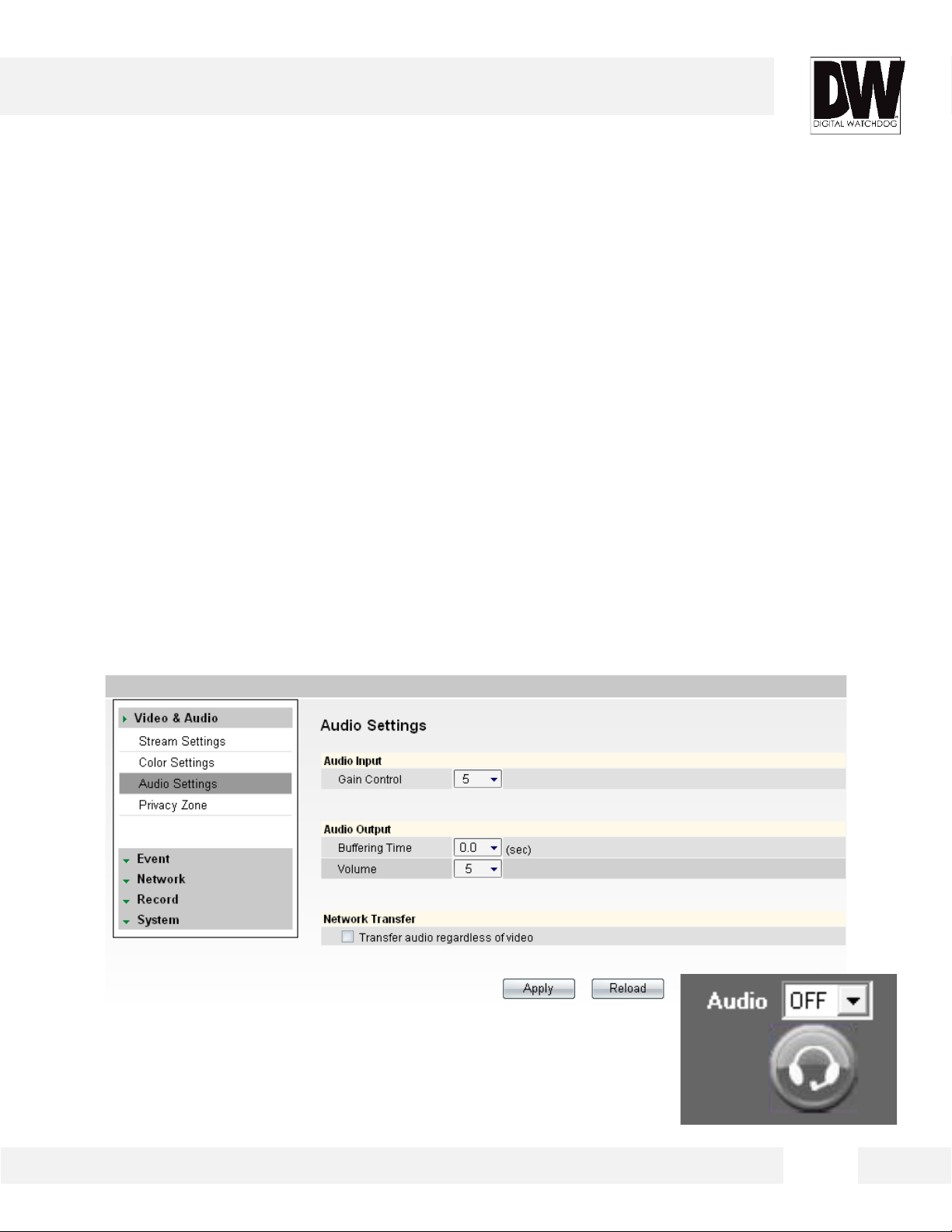
Setup > Video & Audio > Audio
Connect speaker/microphone wires (not included) to your
camera and to a monitoring device (ex.: PC computer).
• On the Display Screen in your Web viewer, go to Setup, Video & Audio, and finally, Audio. Adjust
settings to your preference.
1. Audio Input: Set Gain (0-5).
2. Audio Output: Set Buffering Time & Volume (0-5).
3. Network Transfer: Select Transfer Audio regardless of video.
• On the Display Screen, change Audio (in the bottom left corner) from OFF to 1. This will enable you to
hear external audio.
• To transfer audio to the camera, select the ‘headset’ button beneath Audio.
32
Page 33

WEBVIEWER*
Setup > Video & Audio > Privacy Zone
The MEGAPIX® camera offers up to 30 privacy zone settings.
To set Privacy Zones:
1. Change Mode to On. Click Apply. By default, all 30 privacy zones will be displayed.
2. Select the color of the zone and transparency of the color from the drop down list. Click Apply.
3. Select the zones you want to view and/or modify. Use the Show All button to display all 30 privacy
zones, or Hide All to deselect them and select only a single privacy zone. Click Apply.
4. Set the zone’s size and location, using the grid lines. Under Local Settings, select the zone you want
to modify, then select the position:
- Horizontal Position: 0~57
- Vertical Position: 0~31
- Width: 0~60
- Height: 0~34
5. Click Apply after each modification to
verify the size and position match your
requirements.
33
2
Page 34
WEBVIEWER*
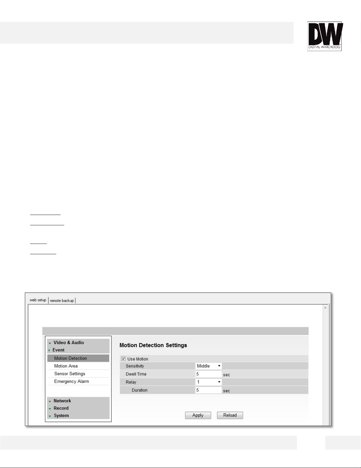
Setup > Event > Motion Detection
The Motion detection feature allows the MEGAPIX camera to
detect motion and trigger an alarm. To set the camera to
send e- mail notifications for every motion triggered alarms,
see page xx.
To setup motion detection:
1. Check the Use Motion box.
2. Sensitivity: Select from Low, Middle, or High.
3. Dwell Time: When a motion is triggered, the camera can be set to record for a certain period of time.
Dwell Time can be set up to 900 seconds.
4. Relay: an alarm out triggered by motion detection. Select None or 1.
5. Duration: determines how long the alarm out will last. Maximum is 900 seconds.
6. Select Apply to save changes.
To setup specific areas of the camera’s view to motion detection, please see the next page.
34
Page 35
WEBVIEWER*
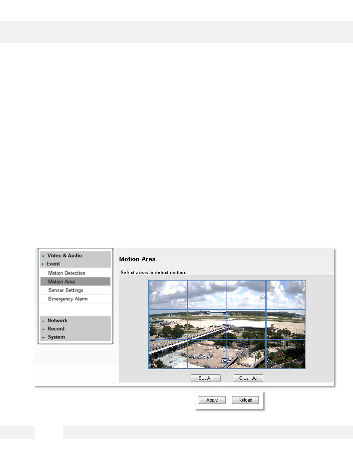
Setup > Event > Motion Area
The Motion detection feature allows the MEGAPIX camera to
detect motion and trigger an alarm. To set the camera to
send e- mail notifications for every motion triggered alarms,
see page xx.
To adjust the camera’s motion detection zones:
1. Hold the left mouse button and drag the mouse pointer over image to select the motion area, or use
Set All button to select the entire screen.
2. Select Clear All to deselect motion areas.
3. Select Apply to save changes.
35
Page 36

WEBVIEWER*
Setup > Event > Sensor Settings
You can connect the camera to an external sensor,
integrating the camera into an existing surveillance solution.
To setup an external sensor:
1. Sensor: Select sensor type(NO/NC) and check sensor number. To use relay out, check relay number
and set time to activate.
- NO(Normal Open): Sensor is activated when it closes. (Example: Door normally remains open and an
alarm is triggered when the door closes.)
- NC(Normal Close): Sensor is activated when it opens. (Example: Window normally remains closed
and an alarm is triggered when the window is opened.)
2. Relay Activity: To use Relay Activity, select USE and set time to activate.
3. Select Apply to save changes.
36
Page 37

WEBVIEWER*
Setup > Event > Emergency Alarm
Send alarm triggered information to predefined destination
(i.e. remote client software).
To setup an external emergency alarm notification:
1. Site Information: Enter the Site Name, Transmission Settings, and Video Duration for the video that
will be sent when motion is detected.
2. Emergency Alarm Recipient List: Enter the IP address and the Port for the remote site(s) to which you
want to send the video. You can set-up up to five different servers. You must set same port to get EA
data.
3. Event for EA: Select which type of event will trigger the alarm – Motion or Sensor.
4. Select Apply to save changes.
37
Page 38

WEBVIEWER*
Setup > Network > Network Settings
Use this setup page to adjust the camera’s network settings.
• IP Mode: Select the type of IP address for the camera.
- DHCP: Select this option if you have a DHCP Server and would like your camera to obtain its
network settings automatically.
- PPPoE: Select this option when you use WAN service. Yo u will need a Username and Password
from your Internet Service Provider.
- Static IP: Manually enter the camera’s network information.
• IP Address: Enter the static IP Address of the camera
• Subnet Mask: default is 255.255.255.0
• Gateway: The gateway is your router’s external (public) IP address. It is used when accessing the
camera from outside the network. The router will channel your data to the correct destination even
if it is on a different subnet mask.
• DNS: Enter Primary DNS and
Secondary DNS. These translate web
addresses to IP addresses.
• IPv6 Mode: If applicable, you can setup
the camera using the IPv6 protocol.
• MAC Address: Displays the camera’s
MAC (Mobile Access Control) Address.
• Port: Displays all the ports necessary
for network communication.
• Reboot your system to apply the
changes to your camera. When you
select Apply, a dialogue box will appear,
notifying you the camera will reboot to
apply the changes. It may take up to 20
seconds for the camera to reboot.
* Contact your Internet Service Provider or Network Administrator for more information.
38
Page 39
WEBVIEWER*
Setup > Network > Dynamic DNS
If you do not use a public IP address, DDNS provides you to
connect on WAN. DDNS allows you to connect to the
MEGAPIX camera with a URL address instead of an IP
address. DDNS automatically redirects traffic to your IP
address every time it changes.
To us e DDNS:
1. Select the Use DDNS checkbox.
2. Select one of the DDNS System Names from the drop down list.
3. Enter Username & Password if needed. The Username & Password must be registered at the DDNS
site.
4. Enter the Host Name.
5. Reboot your system to apply the changes to your camera. When you select Apply, a dialogue box
will appear, notifying you the camera will reboot to apply the changes. It may take up to 20 seconds
for the camera to reboot.
39
Page 40

WEBVIEWER*
Setup > Network > Communication Protocol
Current Protocol displays the current selected protocol.
To change the Protocol:
1. Select one of the three options—TCP, UDP, or Multicast.
2. If you select Multicast, enter the Multicast IP and Multicast Port.
3. Reboot your system to apply the changes to your camera. When you select Apply, a dialogue box
will appear, notifying you the camera will reboot to apply the changes. It may take up to 20 seconds
for the camera to reboot.
40
Page 41
WEBVIEWER*
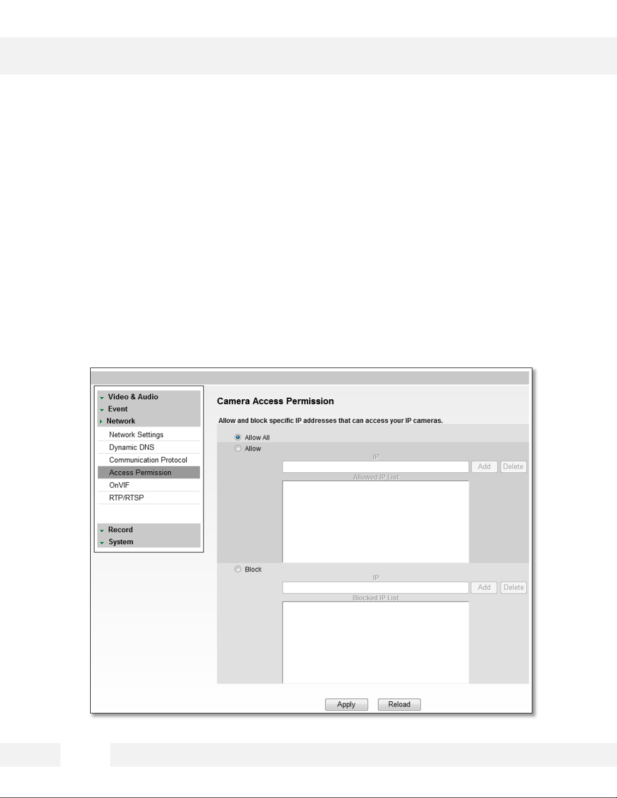
Setup > Network > Access Permission
Use the Access Permission page to allow or block specific
IP addresses to connect to the camera.
1. Select Allow All to allow anyone to connect to this camera. If Allow All is selected, the Allowed IP List
and Blocked IP List will be ignored.
2. To allow only a specific list of IP addresses to connect to this camera, select Allow. Enter an IP
Address and click the Add button.
3. To block a specific list of IP addresses from connecting to this camera, select Block. Enter an IP
Address and click the Add button.
41
Page 42

WEBVIEWER*
Setup > Network > OnVIF
OnVIF is the Open Network Video Interface Forum.
To us e OnVIF:
1. Make sure Enable is checked.
2. Set the Service Port to “8032.”
3. Select On or Off for WS-Security.
4. Select desired Options from the list.
5. Select On or Off for WS-Discovery (Web Services Dynamic Discovery)
6. Select On or Off to Verify Service Address.
7. Select Apply to save changes.
42
Page 43

WEBVIEWER*
Setup > Network > RTP/ RTSP
RTP and RTSP Ports Configuration and Management
Real-time Transport Protocol (RTP) and Real-time Streaming Protocol (RTSP) are data transfer protocol for
delivering live and stored media to one or more clients at the same time. These protocols allow
software to access the first and second stream directly, by assigning each stream its own ports. RTP and
RTSP are used for integration and communication between the cameras and other software.
To use RTP/ RTSP:
1. Check the box to enable authentication on RTSP
2. If necessary, modify the ports for the first and second stream.
3. Click ‘Apply’ so save all changes or ‘Reload’ to view the last saved settings.
43
Page 44

WEBVIEWER*
Setup > Record > Storage Device
This setup screen allows you to view and setup your SD
card for local EMERGENCY recording. The camera will
record to the SD card only when no network connection is
detected.
• Device Information:
- Click the icon Load Device Information to find the SD card connected to the camera.
- The system will display all storage devices currently connected to the camera.
- To activate the SD card to start recording, select Record Start.
- To stop the SD card’s recording, select Record Stop.
• Recording Information:
- This section displays the first and last recorded data available on the selected SD card.
- SD card records video from the second stream. To modify recording quality, please see page xx.
* IMPORTANT: This is an emergency recording feature, designed to record only under a network
loss. If you connect to the camera via the Web viewer or an NVR, the SD card will stop recording.
44
Page 45

WEBVIEWER*
Setup > Record > Schedule
This setup screen allows you to view and setup your SD
card for local EMERGENCY recording. The camera will
record to the SD card only when no network connection is
detected.
Video Schedule
1. Set recording schedule daily or weekly. Default is daily setting. It only saves single day’s setting
without changing to ‘Multi Day Mode.’
2. Select the type of recording: Continuous (Cyan), Motion (Yellow) & Sensor (Red) by clicking on the
corresponding button.
3. Drag your mouse over the hours you want to set for motion recording. The recording mode will be
applied to the hours you selected when you release the mouse’s right-click.
4. To remove scheduled recording for a specific day, select ‘No Record’ and press the box for which
hours you want the recording removed. The box will now appear white.
5. Select Apply to save changes, or Reload to view the last saved settings.
45
Page 46

WEBVIEWER*
Setup > Record > Schedule
This setup screen allows you to view and setup your SD
card for local EMERGENCY recording. The camera will
record to the SD card only when no network connection is
detected.
Recording Control
1. Pre-Alarm Time: Save previous image of event for duration of time.
2. Motion Post-Alarm Time: Save images after motion events for duration of time.
3. Sensor Post-Alarm Time: Save images after sensor events for duration of time.
4. Overwrite: If selected, once the SD card is full, new video will be recorded over older data.
5. Key Frame Only: If selected, the SD card will record only Start and End Key Frame, the main frames
in the series. This option is recommended when you have limited storage space.
6. Select Apply to save changes.
46
Page 47

WEBVIEWER*
Setup > Record > Schedule
This setup screen allows you to view and setup your SD
card for local EMERGENCY recording. The camera will
record to the SD card only when no network connection is
detected.
To backup recorded data from the camera’s SD Card:
1. Go to the Remote Backup Tab in the camera’s Setup menu.
2. On the calendar, select the date for remote backup. Dates with recorded data will appear in bold.
3. Once a day from the calendar is selected, recorded data for that day will appear on the time bar.
Hours with recorded data will be indicated by the pink line.
4. Select the Backup Start Time and Backup End Time.
- Use the start and end time lines to input the desired time.
- Yo u can also use the interactive time bar:
a. Right-click on the time you want to set as Start Time.
b. Left-click on the time you want to set as End Time.
The time frame you have selected will appear in BLUE.
5. Select the Target Drive to save the backup file.
6. Select Backup Start.
7. To cancel a backup in progress,
select Backup Cancel.
47
Page 48
WEBVIEWER*
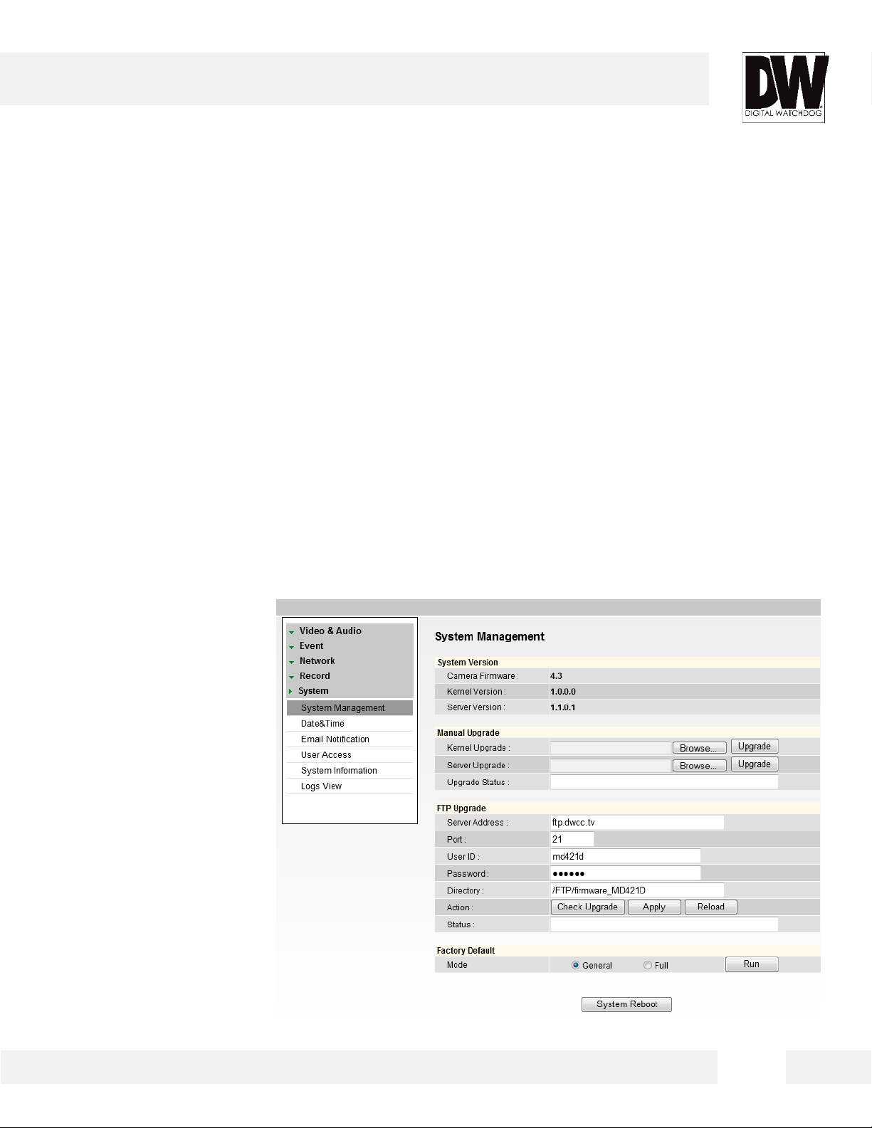
Setup > System > Upgrade
Use this setup screen to view the camera’s current firmware,
upgrade to a new firmware or reset to factory default.
• System Version: Shows the current version of the camera.
• Manual Upgrade: To upgrade system firmware, you have to contact manufacturer and get the
upgrade file first. Go to www.Digital-Watchdog.com and select Support tab.
a. Browse file and select the file.
b. Press Upgrade button. A dialogue box will appear. Select OK. System will automatically reboot.
• FTP Upgrade (all information below will be set to camera default):
a. Server Address: Shows the Digital Watchdog® FTP Server IP address.
b. Port: Default is 21.
c. User ID and Password: FTP Server Log in ID and password
d. Directory: Upgrade File Path.
e. Action: Select Check
Upgrade to display the
Upgrade File list
f. Status: Display progress
of the Upgrade
g. If camera detects an
upgrade, a dialogue box
will appear and the system
will automatically reboot
once the upgrade is
complete.
1
2
3
48
Page 49

WEBVIEWER*
Setup > System > Upgrade
Use this setup screen to view the camera’s current firmware,
upgrade to a new firmware or reset to factory default.
• Factory Default: You can reset the camera to its original factory settings.
a. General: Reset the camera to factory default on all settings except for the IP and Network
configuration.
b. Full: Reset ALL of the camera’s setting, including the network configurations.
49
1
2
3
Page 50
WEBVIEWER*
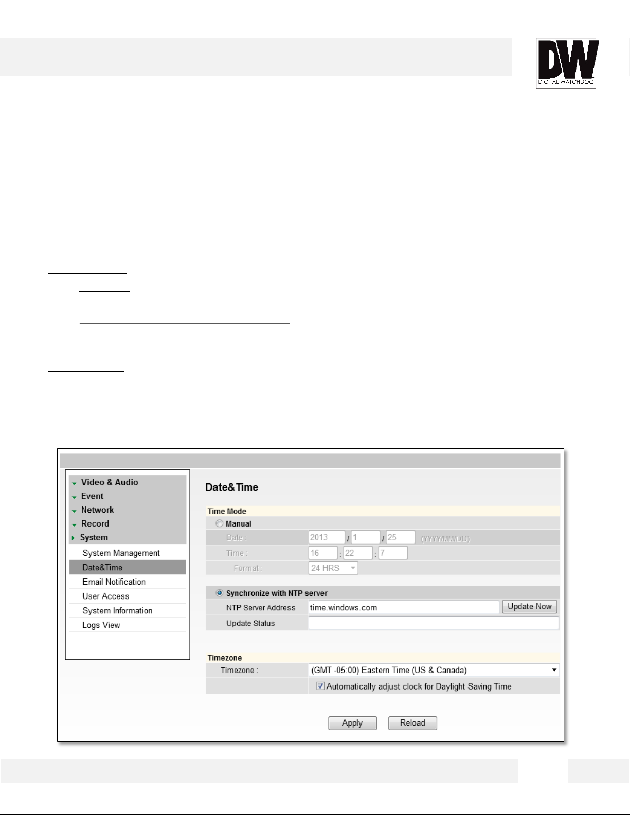
Setup > System > Date & Time
Set date and time information.
• Time Mode:
a. Manual: Insert the Date and Time. Select the type of Format for your
time.
b. Synchronize with NTP Server: This option will allow the camera to
obtain its date and time settings from an NTP server automatically. To
setup, enter an NTP server’s IP address (Example: pool.ntp.org).
• Time Zone: Select the appropriate time zone for the camera from the
available options in the drop- down list.
• Select Apply to save changes.
50
Page 51

WEBVIEWER*
Setup > System > E- mail Notification
Send an e- mail notification when an event is triggered.
1. Select Use Event Mail option. Select Event Type.
2. Enter SMTP Server information. Example: smtp.gmail.com.
3. Enter Username and Password.
4. Enter Sender E-mail.
5. Add the E-mail(s) you wish to send the notifications to.
6. Select Apply to save changes.
*Email Notifications do not support TSL/SSL option. Notifications are TEXT only.
51
Page 52
WEBVIEWER*
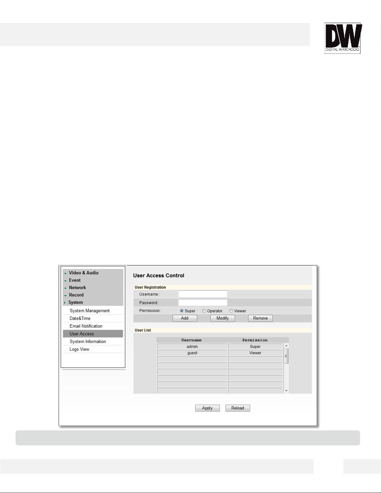
Setup > System > User Access Control
Use this setup screen to add, edit, or delete users with
access to the camera.
To add a new user:
1. Enter Username and Password.
2. Select a Permission type.
- Super: Administrator
- Operator: View and Edit Video and Event Settings Only
- Viewer: View Only
3. Click Add.
4. To modify a user, select the user from the User List, and click Modify.
5. To remove a user, select the user from the User List, and click Remove.
1
3
4
*The maximum number of users who can be added to the User List is twenty.
2
52
Page 53

WEBVIEWER*
Setup > System > System Information
System Information will display all the current camera
settings
You can export a camera’s settings to apply
to other cameras by using the import/
export buttons on this page.
• To Export the settings from the current
camera:
Press the export button. The system
will generate a ‘.bin’ file with all the
cameras settings in your Internet
Explorer ‘Downloads’ page.
• To import settings from a different
camera:
Press the Browse button and locate the
‘.bin’ file you have imported from a
different camera. Select the ‘Import’
button. The system will update the
current camera’s settings with all the
imported information. The progress bar
will display the import process.
53
Page 54

WEBVIEWER*
Setup > System > Logs View
User can view detailed logs for system and/or events
triggered and recorded in the camera.
To view a camera log report:
1. Select the type of report you want to view: System, Event, or System & Event.
2. Press View. The system will generate a report up to 140,000 bits of data.
3. For events to record, make sure the camera is set to record when an event, like motion detection, is
triggered.
4. You can export the log report by pressing ‘Export All’.
54
Page 55
SPECIFICATIONS*
IMAGE
Image Sensor 1/2.8” CMOS Sensor
Total Pixels 2010 (H) X 1109 (V)
Minimum Scene Illumination
F1.2 (30IRE): 0.5 Lux (Color)
F1.2 (30IRE): 0.01 Lux (B/W)
LENS
Focal Length 2.8~12mm
Lens Type Auto Focus P-Iris Lens
OPERATIONAL
Brightness 0~19
Shutter Mode Auto/ Manual
Digital Slow Shutter Off/ 2X/ 3X/ 4X
Shutter Speed 1/30, 1/60/ 1/120
Auto Gain Control 0~20
Back Light Compensation Off/ On
Day and Night Auto/ Day (Color)/ Night (B/W)
Lens Mode Manual/ DC/ AF
Chroma (Color Quality: Hue, &
Saturation Settings)
0~20
Sharpness 0~10
Mirror & Flip Off/ On
3D- Digital Noise Reduction Off/ Low/ Middle/ High
Privacy Zone Off/ On (30 Programmable Zones)
Motion Detection: Sensitivity Low/ Middle/ High
Audio Communication Two-Way
Digital Zoom 8X Digital Zoom
Sensor 1 Input/ 1 Output Built-In
Remote Backup Up to 24 HR Backup to Local Directory
55
Page 56

SPECIFICATIONS*
NETWORK
LAN 802.3 Compliance 10/100 LAN
Video Compression Type H.264, MPEG4, MJPEG (Super Fine ~ Low)
Resolution 1920X1080 (16:9) ~ 320X240 (4:3)
Frame Rate Up to 30fps at All Resolutions
Stream Capability Dual-Stream at Different Rates and Resolutions
IP IPv4, IPv6
Protocol TCP/IP, HTTP, DHCP, PPPoE, ICMP, ARP, RARP, RTSP, NTP, UDP, Multicast
Maximum User Access 20 Users
Memory Slot Local SDHC Card Backup
ONVIF Conformance Yes
Supported OS: Windows XP, Windows Vista, Windows 7, MAC OS
Web Viewer
Supported Browser: Internet Explorer, Google Chrome, Mozilla Firefox,
Safari
Video Management Software DW Spectrum™ IPVMS
ENVIRONMENTAL
Operating Temperature/ Humidity -29°C ~ 55°C (-20°F ~ 131°F)
Operating Humidity Less than 90% (Non-Condensing)
IP Rating IP68 (protects against Dust and Immersion Beyond 3ft).
Other Specifications CE, FCC, RoHS
Electrical
Power Requirement DC 12V, PoE (IEEE802.3af Class 3)
IR OFF: 7.2w, 600mA
Power Consumption
IR ON: I8.64W, 720mA
Mechanical
Housing Material Aluminium
Dimensions 139 X 118.8 mm (5.47 X 4.7 in)
Weight 2.05 lbs
54
Page 57

TROUBLESHOOTING
Before sending your camera for repair, check the following or contact your technical specialist.
I can’t find my MEGAPIX camera on the IP Finder software.
Is the PoE cable connected properly?
Make sure cable is tightly connected at both ends. It should make a “click” sound when connected properly. Make
sure cable is intact and there are no cuts or exposed wires.
If Yes, are the camera’s LED lights turned on and blinking?
The camera’s LED lights indicate that the camera is powered on. Blinking LED lights indicate that the camera has
finished booting up and is transmitting data.
If Yes, is the internet working properly?
Make sure you can connect to the internet with other devices on the network (ex. your computer). Your internet
could be temporarily down.
If Yes, if using a power adaptor, does it meet camera’s power requirements? Power Requirements: DC12V (IR OFF:
7.2w, 600mA IR ON: I8.64W, 720mA), PoE Ports (Class 3)
If Yes, if using PoE Switch, is it connected to a proper internet outlet and operating properly?
Make sure the PoE Switch is connected to a router/modem and the ports that have devices connected to them
have a green LED on.
If Yes, is the computer on the same network as the MEGAPIX camera?
Camera and computer should be connected to the same router. Contact your network administrator if you have
more than one network available.
If Yes, try pinging the IP camera’s default IP address 192.168.1.123.
From your desktop, go to Start > Programs > Accessories > Command Prompt. Type “ping 192.168.1.123” and press
Enter. If you get the message “Request timed out,” camera is not connected. Camera is connected if you get data.
If Yes, try connecting the camera to a differ port in the PoE Switch.
That specific Switch Port may be damaged or currently not working properly.
If Yes, try resetting the camera to default settings.
Press the reset button on the control board and hold for 5 seconds. The camera will return to factory default with
default IP address 192.168.1.123. If your network supports DHCP, the camera will be found using the IP Finder
software with an IP address that matches your network’s requirements.
57
Page 58

TROUBLESHOOTING
Before sending your camera for repair, check the following or contact your technical specialist.
I can’t connect to my MEGAPIX camera through the Web Browser.
Are the camera’s LEDs on and blinking?
The camera’s LED indicates the camera is On. If the LED blinks, the camera has finished booting up and is
transmitting data.
If Yes, is the internet working properly?
Make sure you connect to the internet with other devices on the network (ex. your computer). Your internet could
be temporarily down.
If Yes, is the computer on the same network as the IP camera?
Camera and computer should be connected on the same router. Contact your network administrator if you have
more than one network available.
If Yes, try pinging the MEGAPIX camera’s IP address as it appears on the IP finder.
From your desktop, go to Start > Programs > Accessories > Command Prompt. Type “ping” followed by the
camera’s IP address; then, press Enter. If you get the message “Request timed out,” camera is not connected. If
you get data back, that means the camera is connected.
If Yes, try connecting the camera, to a different port in the PoE Switch.
That specific Switch Port may be damaged or currently not operating properly.
If Yes, check your security settings on your internet browser.
Try adding the camera’s IP address to the trusted sites list in your Internet Options. *Setup may vary depending
on the browser you use.
58
Page 59

TROUBLESHOOTING
Before sending your camera for repair, check the following or contact your technical specialist.
I can’t see the live video of my MEGAPIX camera.
Are you trying to view the camera’s video from an Internet Explorer browser?
Make sure you have the minimum PC requirements to view the MEGApix® Snapit™ camera. See below for
more information.
If Yes, did you install ActiveX files?
When you connect to your MEGAPIX camera for the first time, your browser will ask you to install ActiveX. Make
sure your Web Browser’s security settings do not block pop-up windows and allows ActiveX files to be installed
and used. *Setup may vary depending on the browser you use.
If Yes, verify nothing is blocking the camera’s lens.
Are you trying to view the camera’s video from a different browser than Internet Explorer (ex. Google Chrome,
Mozilla Firefox, MAC Safari)?
If Yes, at least one of the streams of the camera must have codec (Compression Type) set to MJPEG.
Go to the camera’s setup menu. Select Stream Settings. Select one of the streams and change its codec to
MJPEG. Click Apply to save changes. Go back to live screen and at the bottom of the screen, select the stream
you have set to MJPEG. Live video will start streaming to your web browser.
Web Viewer Specifications
Minimum Requirements for PC
CPU Intel P4 2.0GHz Dual Core
RAM More than 1GB
HDD 200 GB Required for Saving Clip Image
OS Microsoft Windows XP or Higher
Resolution Higher than 1024X768
59
Page 60

TROUBLESHOOTING
Before sending your camera for repair, check the following or contact your technical specialist.
Setting the IP Address for your PC
Dynamic Host Configuration Protocol (DHCP) is the default setting for the camera.
If the MEGAPIX camera is connected to a DHCP network and the camera’s IP Configuration Mode is set to DHCP, the
server will automatically assign an IP address to the camera. If the camera is using DHCP, the default IP address will
be 192.168.1.123, and the default subnet mask will be 255.255.255.0.
The MEGAPIX camera can also connect to the web viewer using a static IP address. This will allow you to set your
own IP address manually.
Setup the Network Protocol on your PC.
1. Go to Network icon on your PC.
2. Right-click and select Properties.
3. Double-click Local Area Connection.
4. Click Properties.
5. Double-click Internet Protocol Version.
6. Select “Obtain an IP address automatically” to set the computer to a dynamic IP address, or select “Use the
following IP address” to set the computer to a static IP address.
7. If the option “Use the following IP address” has been selected, setup the IP address as 192.168.1.XXX. The last
three digits should be a number between 1 and 254.
60
Page 61

WARRANTY INFORMATION*
Digital Watchdog (referred to as “the Warrantor”) warrants the Camera against defects in materials or workmanships
as follows:
Labor: For the initial five (5) years, one (1) year for IR LED, from the date of original purchase if the camera is
determined to be defective, the Warrantor will repair or replace the unit with new or refurbished product at its option, at
no charge.
Parts: In addition, the Warrantor will supply replacement parts for the initial five (5) years, one (1) year for IR LED.
To obtain warranty or out of warranty service, please contact a technical support representative at 1-866-446-3595
Monday through F riday from 9:00AM to 8:00PM EST.
A purchase receipt or other proof of the date of the original purchase is required before warranty service is rendered.
This warranty only covers failures due to defects in materials and workmanship which arise during normal use. This
warranty does not cover damages which occurs in shipment or failures which are caused by products not supplied by
the Warrantor or failures which result from accident, misuse, abuse, neglect, mishandling, misapplication, alteration,
modification, faulty installation, set-up adjustments, improper antenna, inadequate signal pickup, maladjustments of
consumer controls, improper operation, power line surge, improper voltage supply, lightning damage, rental use of the
product or service by anyone other than an authorized repair facility or damage that is attributable to acts of God.
61
Page 62

LIMITS & EXCLUSIONS*
There are no express warranties except as listed above. The Warrantor will not be liable for incidental or consequential
damages (including, without limitation, damage to recording media) resulting from the use of these products, or arising
out of any breach of the warranty. All express and implied warranties, including the warranties of merchantability and
fitness for particular purpose, are limited to the applicable warranty period set forth above.
Some states do not allow the exclusion or limitation of incidental or consequential damages or limitations on how long
an implied warranty lasts, so the above exclusions or limitations may not apply to you. This warranty gives you specific
legal rights, and you may also have other rights from vary from state to state.
If the problem is not handled to your satisfaction, then write to the following address:
Digital Watchdog, Inc.
ATTN: RMA Department
5436 W Crenshaw St
Tampa, FL 33634
Service calls which do not involve defective materials or workmanship as determined by the Warrantor, in its sole
discretion, are not covered. Cost of such service calls are the responsibility of the purchaser.
62
Page 63

Headquarters Office: 5436 W Crenshaw St, Tampa, FL 33634
Sales Office: 16220 Bloomfield Ave., Cerritos, California, USA 90703
PH: 866-446-3595 | FAX: 813-888-9262
www.Digital-Watchdog.com
technicalsupport@dwcc.tv
Technical Support PH:
USA & Canada 1+ (866) 446-3595
International 1+ (813) 888-9555
French Canadian 1+ (514) 360-1309
Technical Support Hours: Monday-Friday
9:00am to 8:00pm Eastern Standard Time
 Loading...