

Page 1
High Resolution Bullet Camera
DWC-B1362TIR650
ABOUT MANUAL
Before installing and using the camera, please read this manual carefully.
Be sure to keep it handy for future reference.
08092012
Page 2

PRECAUTIONS
Do not open or modify.
Do not open the case except during maintenence and installation,
for it may be dangerous and can cause damages.
Do not put objects into the unit.
Keep metal objects and flammable substances from entering the camera.
It can cause fire, short-circuits, or other damages.
Be careful when handling the unit.
To prevent damages, do not drop the camera or subject it to shock or vibration.
Do not install near electric or magnetic fields.
Protect from humidity and dust.
Protect from high temperature.
Be careful when installing near the ceiling of kitchen or a boiler room,
as the temperature may rise to high levels.
Cleaning
To remove dirt from the case, moisten a soft cloth with a soft detergent solution and wipe.
Mounting Surface.
The material of the mounting surface must be strong enough to support the camera.
FCC COMPLIANCE
This equipment has been tested and found to comply with the limits for a Class B digital device, pursuant
to part 15 of the FCC rules. These limits are designed to Provide reasonable protection against harmful
interference. when the equipment is operated in a residential environment. This equipment generates, uses,
and radiates radio frequency energy; and if it is not installed and used in accordance with the instruction
manual, it may cause harmful interference to radio communications.
WARNING : Changes or modifications are not expressly approved by the manufacturer.
22
Page 3

Table of Contents
Introduction
Installation
Troubleshooting
Warranty Information
Specifications
Memo 18-19
Features
Parts and Descriptions
Dimensions
Included Accessories
Surface Mount Installation
Connecting to Monitors
Camera’s Control Board
Adjusting the Camera’s Lens
Adjusting the Camera’s Angle
14-15
16-17
4
5
6
7
8
9
10
11
12
13
3
Page 4

FEATURES*
1/3” Sony Super HAD Ⅱ CCD
570TV Lines (B/W), 540TV Lines (Color)
6 ~ 50mm Varifocal Auto Iris Lens
250ft Range IR with Intelligent Camera Sync
True Day & Night / TDN5 (Electro Magnetic Mechanism)
DRC (Dynamic Range Compressor)
HME (Highlight Masking Exposure)
SLC (Side Light Compensation)
AGC / BLC / AWB
Negative Imaging
Mirror Image Control
RS485 Built-In
Programmable Privacy Zone (4) & Motion Detection
Easy Icon Driven OSD Menu with Built-In Joystick
Auto Sensing 12VDC or 24VAC with Line Lock
Secondary Video-BNC Output
4
Page 5
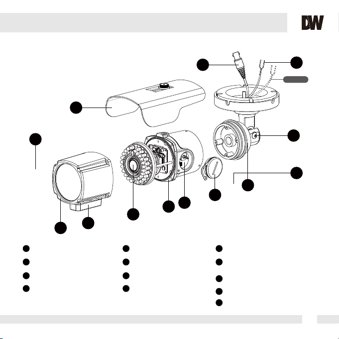
PART & DESCRIPTIONS*
3
9
10
RS 485
OPTION
11
2
1
1
Front Case
2
Zoom, Focus Housing
3
Sunshield
4
Lens
4
5
Rear Case
6
Control Board
7
Con Cap
8
Double Arm Bracket
5
12
13
8
6
7
9
BNC Jack
10
Power Input Connector
DC 12V / AC24V Voltage
11
Assembly Screw
12
Fixing Screw
13
Set Screw
5
5
Page 6
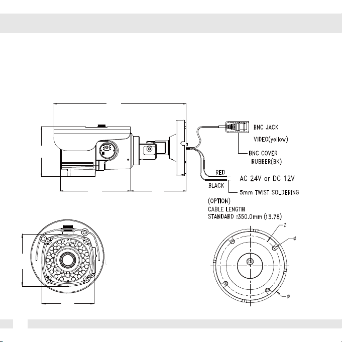
DIMENSIONS IN MILLIMETERS*
230.0
(9.05”)
86.5
(3.4”)
68
(2.67”)
6
68
(2.67”)
122
(4.8”)
96.5
(3.8”)
78
(3.07”)
(3.77”)
96
(0.2”)
5
Page 7

INSIDE THE BOX*
Included with B2 Bullet Camera
1
User Manual
2
Mounting Template
3
4 Machine Screws and 4 Dry Wall Anchors
4
Secondary Video-BNC Cable
Bullet Camera
ABOUT MANUAL
Before installing and using the camera, please read this manual carefully.
Be sure to keep it handy for future reference.
5
L-Key
6
Double-Sided TORX-T20 Hex Key
7
Page 8

SURFACE MOUNT INSTALLATION INSTRUCTIONS*
Use the 4 mounting screws to install the camera on the
*Installation Using a Junction Box
8
wall or ceiling.
Then, follow the next step on the pages 9-12.
NPT 3/4” Pipe
*Note: Electrical junction box and required screws sold separately.
Page 9

CONNECTING TO MONITORS*
Use the diagram below to connect to a Monitor or CRT Monitor properly.
12VDC/24VAC
Left
Second Video Output
Monitor
Power connection - 12VDC/24VAC Dual Voltage (Auto Polarity Detection and Protection)
All camera are equipped with a second video output for on-site configuration.
CCTV Monitor
Up
Right
Down
9
Page 10

CONTROL BOARD*
Joystick: Controls the OSD menu.
Secondary Connector:
Video Output Connector for
On-Site Configuration
1
Remove clear plastic ring from the control cap.
2
Turn control cap counter-clockwise until cap separates completely from the camera body.
10
Page 11

ADJUSTING THE CAMERA LENS*
Follow the instructions provided below to make any lens adjustments.
FOCUS
1
To adjust the field of view, use the L-Key to turn the zoom screw (located on the bottom of the
camera) counter-clockwise to zoom in, or clockwise to zoom out.
2
Adjust the focus the same way as descriped above AFTER the desired zoom position is established.
ZOOM
11
Page 12

ADJUSTING THE CAMERA ANGLE*
CAUTION :
1
Do not rotate more than 360o.
2
Do not unnecessarily twist too many times.
12
Page 13

TROUBLESHOOTING
Before sending your camera for repair, check the following or contact our technical
specialist.
FOR NO VIDEO
Check the coaxial cable and make sure it is connected securely.
Check the lens’ iris adjustment at the camera’s OSD menu.
Check the power supply and make sure the camera has the proper voltage and
current.
FOR OUT-OF-FOCUS VIDEO
Check the clear dome cover and the lens for dirt or fingerprints. Use a soft cloth and
gently clean. Check the lens’ manual focal and zoom adjustment. The use of a field
test monitor is recommended.
13
Page 14

WARRANTY INFORMATION*
Digital Watchdog (referred to as “the Warrantor”)
warrants the Digital Watchdog Camera against defects in
materials or workmanship as follows:
LABOR : For the initial five (5) years and one (1) year on IR LED
from the original purchase date,
if the camera is determined to be defective, the Warrantor will
repair or replace the unit with a new or refurbished product at its
option at no charge.
PARTS : In addition, the Warrantor will supply
replacement parts for the initial five (5) years and one (1) year on IR LED.
To obtain warranty or out of warranty service,
please contact a Technical Support Representative at
1-866-446-3595 Monday through Friday from 8:30AM to 8:00PM
Eastern Standard Time.
A purchase receipt or other proof of the original purchase date is required
before warranty service is rendered. This warranty only covers failures due to
defects in materials and workmanship which arise during normal use.
This warranty does not cover damage which occurs in shipment or failures
which are caused by products not supplied by the Warrantor or failures
which result from accident, misuse, abuse, neglect, mishandling,
misapplication, alteration, modification, faulty installation, set-up adjustments,
improper antenna, inadequate signal pickup, maladjustment of consumer controls,
improper operation, power line surge, improper voltage supply, lightning damage,
rental use of the product or service by anyone other than an authorized repair
facility or damage that is attributable to acts of God.
14
Page 15

LIMITS AND EXCLUSIONS*
There are no express warranties except as listed above.
The Warrantor will not be liable for incidental or consequential
damages (including without limitation or damage to recording media),
resulting from the use of these products or arising out of any breach
of the warranty. All express and implied warranties, including the
warranties of merchantability and fitness for particular purpose,
are limited to the applicable warranty period set forth above.
Some states do not allow the exclusion or limitation of incidental
or consequential damages, or limitations on how long an implied
warranty lasts, so the exclusions or limitations listed above may not
apply to you. This warranty gives you specific legal rights, and you
may also have other rights that vary from state to state.
If the problem is not handled to your satisfaction,
then write to the Address listed on the next page.
Service calls which do not involve defective materials or
workmanship as determined by the Warrantor, in its sole
discretion, are not covered. Costs of such service calls are
the responsibility of the purchaser.
15
Page 16

SPECIFICATION*
VIDEO
Image Sensor 1/3" CCD
Total Pixels 811 (H) x 508 (V), 411K Pixels
Effective Pixels 768 (H) x 494 (V)
Scanning System 525 Lines, 2 : 1 Interlace
Frequency 15.734KHz (H), 59.95Hz (V)
Synchronization Internal / Line Lock
Horizontal Resolution 540 TV Lines [Color], 570 TV Lines [B&W]
Minimum Illumination F1.2 (30IRE): 0.01 Lux [Color]
F1.2 (30IRE): 0.00 Lux [B&W]
S/N Ratio 50dB (AGC off)
Video Output CVBS: 1.0Vp-p / 75 Ω
LENS
Focal Length 6~50mm
Lens Type DC Auto Iris
IR Distance 250ft Range IR
OPERATIONAL
Shutter Speed X2-X256, 1/60s-1/100000s
Back Light Compensation OFF / BLC
Auto Gain Control OFF / LOW / MIDDLE / HIGH
White Balance AWC / ATW / PUSHLOCK / MANUAL
16
Page 17

SPECIFICATION*
OPERATIONAL
Day & Night Mode AUTO / COLOR / B&W
Mirror OFF / ON
Sharpness 0-49
HME OFF / ON
SLC OFF / ON
3D Digital Noise Reduction OFF / ON (0-100)
Dynamic Range Compressor OFF / ON
Privacy Zones OFF / ON (4 Programmable Zones)
Language ENGLISH /CHINESE
ENVIRONMENTAL
Operating Temperature -10oC ~ 55oC (14oF ~ 131oF)
Operating Humidity Less than 90% (Non-Condensing)
Storage Temperature -20oC ~ 70oC (-4oF ~ 158oF)
IP Rating IP66
ELECTRICAL
Power Requirement Dual (12VDC & 24VAC)
Power Consumption 12VDC: 3.8W, 316.7mA / LED ON 6.6W, 550mA
24VAC: 4.2W, 175mA / LED ON 7.1W, 295.8mA
MECHANICAL
Housing Material Aluminum
Dimensions 222X89mm (8.7X3.5In)
Weight 1.5 lbs
17
(Protects against dust and high pressure water.)
Page 18

MEMO*
18
Page 19

19
MEMO*
Page 20

5436 W Crenshaw St. Tampa, FL 33634
Tel : 866-446-3595 / 813-888-9555
Fax : 813-888-9262
www.Digital-Watchdog.com
technicalsupport@dwcc.tv
Technical Support Hours : Monday-Friday
8:30am to 8:00pm Eastern Time
 Loading...