

Digital View VideoFlyer VF-200 User Manual
VideoFlyer 20”
Model : VF-200
User Guide
Introduction
The following is intended as a guide to installation and initial setup of the standard 20”
VideoFlyer, an Internet connected digital video player and display.
This Guide covers:
• Mounting information: How to attach the unit to a fixture
• Installation of a Compact Flash (CF) memory card
• Power: On/off, power considerations
• Setup using the optional 8 segment touch screen
• Operation: How to play video on VideoFlyer
Preparation
It is advisable to do a quick check that the display is working properly prior to installation. Simply
install the CF card as explained below and then power on. If the unit powers up then proceed with
installation.
CF Card Installation
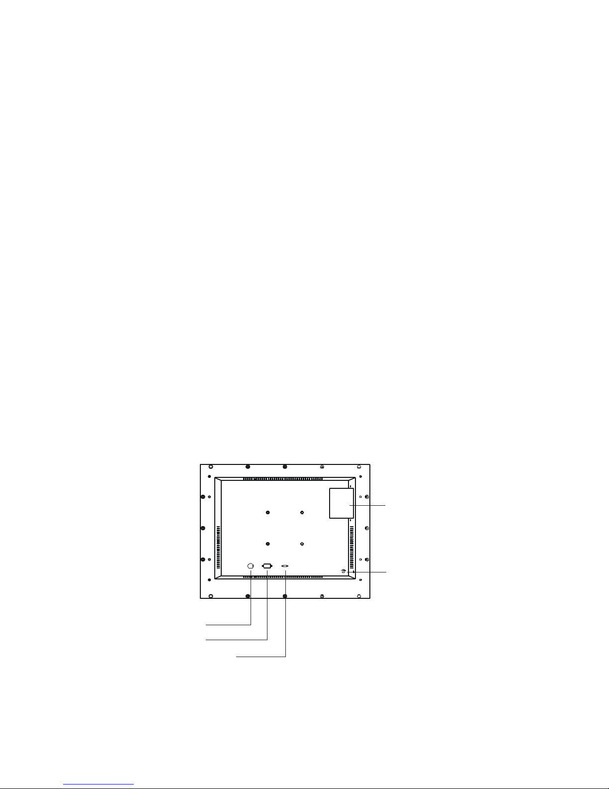
• Remove the access cover on the rear of the display unit, see diagram.
• The CF card should be inserted carefully with the label side visible. WARNING: Do not force
the CF card. Forcing the CF card can damage the connector pins in the display unit and result
in expensive repairs.
• To eject the card push the Eject button as shown in the diagram.
20” VideoFlyer User Guide July 2006 v.m4.0
Volume
DC 12V
RS - 232
Normal Test
CF Car d
com partme nt
Volu me
Con trol
Powe r in
RS- 232
Test / Nor mal swit ch
(Def ault se t to No rmal)
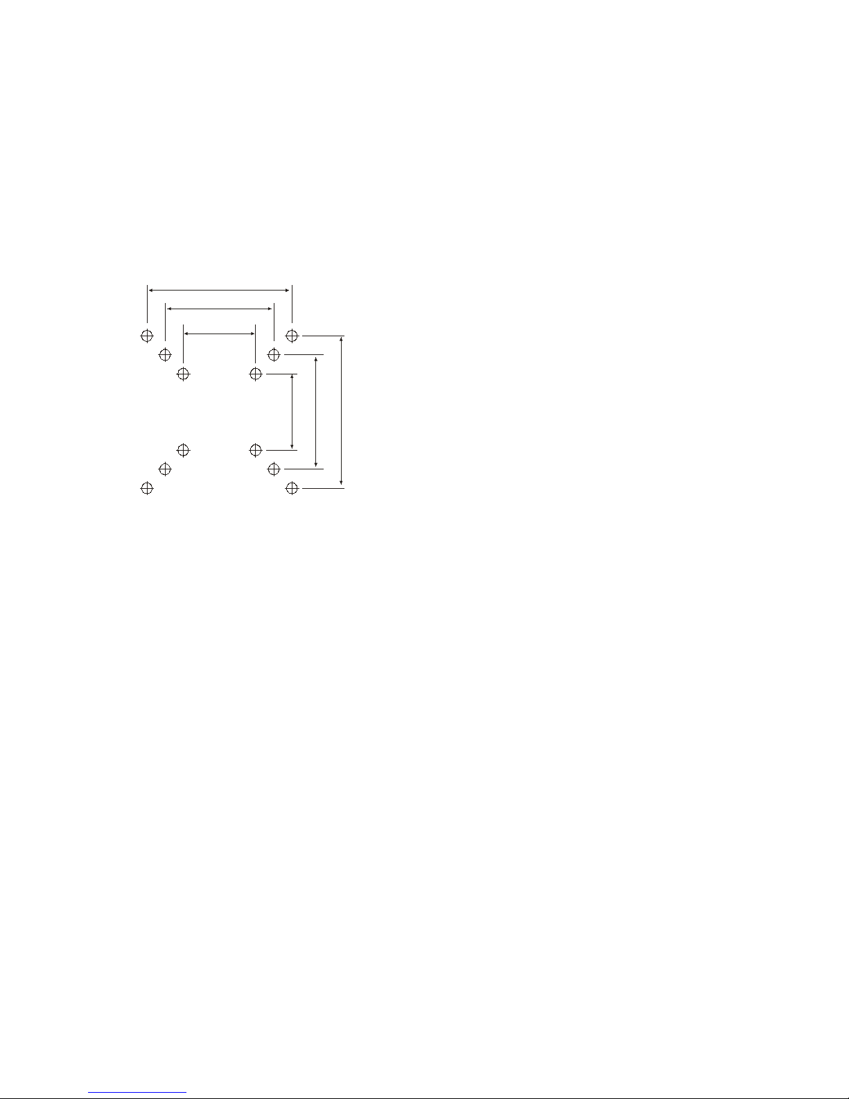
Mounting
The housing is of metal construction and has 4 threaded mounting holes on the rear of the
housing, (see diagram below).
Points to note:
Mounting: It is recommended to use a mounting bracket that allows the display to be set to the
ideal viewing angle.
Sound: Speakers are on the bottom of the housing, ensure they are not covered.
The diagram shows the mountin holes used on the
VideoFlyer Range. The 20" model has both holes Ref A
and B available.
Ref Standard
A
VESA
B
VESA
C Digital View
Use mounting holes reference A or B, ie 100mm and
75mm spacing
Power
The display system is supplied with an AC to DC power adaptor. This should be connected to the
mains.
The power switch is mounted on the back of the housing, ensure the unit is switched on. If you
have a custom version with no power switch on the housing then the unit will power on
immediately it is connected to the power supply. If it does not then please check the power supply.
Notes:
Power input: 12V DC, 6A (min.)
Power cord: You need an AC power cord that is certified for the country or region you are
located. Using an improper power cord might cause severe damage to your unit.
20” VideoFlyer User Guide July 2006 v.m4.0
Screws are 4mm diameter
100mm (A)
100mm (A)
75mm (B)
75mm (B)
50mm (C)
50mm (C)
 Loading...