

Digital View SVX-4096-VW Instructions Manual
Specifications subject to change without notice
© Digital View Ltd – Ver 1.0 August 24, 2017 (SVX-4096-VW_manual.doc) Page 1 of 52
DVI, DISPLAY PORT, HDMI INTERFACE CONTROLLER
FOR TFT PANEL
Model: SVX-4096-VW
Part number : 41762001X-3 or up
INSTRUCTIONS
CONTENTS
Page: 2. Introduction, How to Proceed, Usage Note, Disclaimer
3. System design – Diagram of a suggested system
5. Assembly notes – Important information about system elements
7. Connection & Operation – How to use the controller
13. Connectors, pinouts & jumpers – Essential connection information
27. Controller dimensions
28. Application notes
30. Troubleshooting
31. Specifications
32. Appendix I – Network connection
33. Appendix II – RS-232 control protocols and command set
44. Appendix III - Mapping definition
46. Appendix IV – DV remote control unit work for SVX-4096-VW
47. Appendix V – Functions list on browser page
50. Warranty, Caution & Limitation of Liability, Trademarks
51. Contact details
52. Revision History
It is essential that these instructions are read and understood before connecting or
powering up this controller.
Specifications subject to change without notice
© Digital View Ltd – Ver 1.0 August 24, 2017 (SVX-4096-VW_manual.doc) Page 2 of 52
Introduction
Designed for LCD monitor and other flat panel display applications, the SVX-4096-VW is a feature rich interface controller for :
TFT (active matrix) LCD panels of 4096x2160 resolutions in 60Hz with V-by-One interface.
TFT (active matrix) LCD panels of 1920x1080 resolution in 60Hz with LVDS interface.
Support true 10 bits panel.
Support HDMI, DVI and Display Port input.
HOW TO PROCEED
Ensure you have all parts & that they are correct, refer to:
Connection diagram
Connector reference (in following section)
Assembly notes
Check controller switch & jumper settings (errors may damage the panel)
Prepare the signal sources
Connect the parts
Understand the operation & functions
IMPORTANT USAGE NOTE
This equipment is for use by developers and integrators, the manufacturer accepts no liability for damage or injury caused by
the use of this product. It is the responsibility of the developer, integrators or other user of this product to:
Ensure that all necessary and appropriate safety measures are taken.
Obtain suitable regulatory approvals as may be required.
Check power settings to all component parts before connection.
DISCLAIMER
There is no implied or expressed warranty regarding this material.
Controller Solution Generator
Full web resource matching controllers & panels with connection diagrams for download.
See at : http://www.digitalview.com/csg
Specifications subject to change without notice
© Digital View Ltd – Ver 1.0 August 24, 2017 (SVX-4096-VW_manual.doc) Page 3 of 52
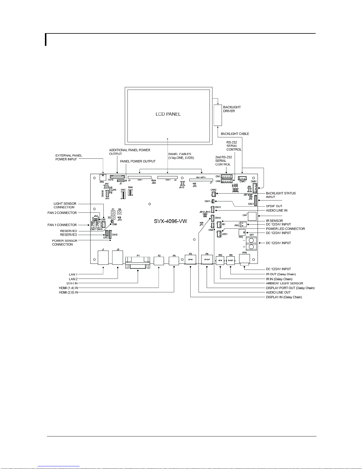
SYSTEM DESIGN
A typical LCD based display system utilizing this controller is likely to comprise the following:
Specifications subject to change without notice
© Digital View Ltd – Ver 1.0 August 24, 2017 (SVX-4096-VW_manual.doc) Page 4 of 52
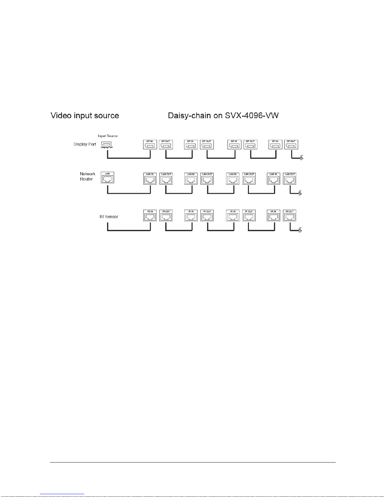
Daisy Chain connection diagram:
To use more SVX-4096-VW connected to each other, connect one end of the signal input cable (DP cable, LAN cable and IR cable)
to the ‘OUT’ connector of SVX-4096-VW board and connect the other end to the ‘IN’ connector of next SVX-4096-VW board.

Specifications subject to change without notice
© Digital View Ltd – Ver 1.0 August 24, 2017 (SVX-4096-VW_manual.doc) Page 5 of 52
ASSEMBLY NOTES
This controller is designed for monitor and custom display projects using 4096x2160 resolution with V-by-One interface or LVDS TFT
panels. The following provides some guidelines for installation and preparation of a finished display solution.
Preparation: Before proceeding it is important to familiarize yourself with the parts making up the system and the various connectors,
mounting holes and general layout of the controller. As much as possible connectors have been labeled. Guides to connectors and
mounting holes are shown in the following relevant sections.
1. LCD Panel: This controller is designed for typical V-by-One (8 lanes) and LVDS interfaced panels with panel voltage 3.3V(4A),
5V(4A), 10V(4A), 12V(4A) or 18V(3A), External for 10V, 12V and 18V interface. Due to the variation between manufacturers of
panels signal timing and other panel characteristics, factory setup and confirmation should be obtained before connecting to a
panel. (NOTE: Check panel power jumper settings before connection)
2. LCD Controller: Handle the controller with care as static charge may damage electronic components. Make sure correct jumper
to match the target LCD panel.
3. Panel cable: In order to provide a clean signal it is recommended that all panel cables (V-by-One signal and LVDS) supplied by
Digital View. Care should be taken when placing the cables to avoid signal interference.
4. Inverter/Backlight driver: This will be required for the backlight of an LCD, some LCD panels have an inverter/backlight driver
built in. As LCD panels may have 1 or more backlight tubes and the power requirements for different panel backlights may vary it
is important to match the inverter/backlight driver in order to obtain optimum performance. See Application notes page 27 for
more information on connection.
5. Inverter/backlight cables: Different inverter/backlight models require different cables and different pin assignment. Make sure
correct cable pin out to match the inverter/backlight. Using wrong cable pin out may damage the inverter/backlight.
6. Function Controls: The following section discusses the controls required and the section on connectors provides the detail. The
controls are minimal: On/Off, Backlight Brightness (depends on inverter), OSD (5 momentary buttons) analog VR type or (8
momentary buttons) digital type.
7. Function controls cable: The cables to the function switches should be of suitable quality and length so that impedance does
not affect performance. Generally lengths up to 1 meter (3 feet) should be acceptable.
8. Optional LED: The pin direction of the LED should be corrected for right color indication. Red color stands for standby. Green
colors stands for signal on. The status LED is an optional part only, can be unconnected.
9. Optional IR sensor: It is an optional part only, can be unconnected if not using IR remote control.
10. RS-232 control interface : Serial control via this interface port.
11. External panel power output : User for specific panel model.
12. Panel control signal : Use for specific panel model.
13. SPDIF Audio output : This port support SPDIF audio output from the HDMI / Display Port audio source inputted.
14. Ambient light sensor connection : 3 ways connector provides interface for ambient light sensor connection by using Kit 70220-3.
15. Backlight status input : 2 ways connector provides interface for connection with the specific panel type which support the panel
with backlight status monitoring function.
16. DVI-I input cable : Plug the DVI cable to the connector P1 on the controller board.
17. HDMI input : Plug the HDMI cable to the connector P2(HDMI 1.4) / P4(HDMI 2.0) on the controller board.
18. Control over network connection : This is a network device that allow to control RS-232 enable devices over a TCP/IP based
Ethernet and the Internet using a web browser. Please refer to Appendix V in details.
19. Reserved for Audio adaptor board P/N 416940020-3: The audio add-on board gives the audio input and output signal
connection. It is an optional and reserved part only, can be unconnected if not using audio. It requires an audio cable P/N
426451800-3 to connect SVX-4096-VW (CN14) to the Audio Add-on Board (CN2).
CAUTION : The Audio Add-on Board P/N 416940020-3 can only operate with 12VDC power input environment.
20. Reserved for Audio extend cable : The audio extend cable P/N 426009700-3 designs for connection between audio add on
board P/N 416940020-3 and the controller. It is an optional and reserved part only, can be unconnected if not using audio.
21. Additional panel power input : Provide additional (+10V/+12V/+18V) panel power input for driving high power consumption
panels.

Specifications subject to change without notice
© Digital View Ltd – Ver 1.0 August 24, 2017 (SVX-4096-VW_manual.doc) Page 6 of 52
22. Power Input: 12V/24VDC is required, this should be a regulated supply. The power rating is depending on the panel and inverter
used. Normally, power supply with 3.5A current output should enough for most of 4xCCFT panels. Although the controller
provides power regulation for the LCD power this does not relate to the power supplied to the backlight inverter.
If an unregulated power supply is provided to an inverter any fluctuations in power may affect operation, performance and lifetime
of the inverter and or backlight tubes.
23. External panel power input : Allow to supply external power to the panel separately for max 3.3V (7A) or 5V (7A) or 10V (5A) or
12V (5A) or 18V (3.5A) via PP4 power input connector. Corresponding jumper setting of JA3, JA5 & JA6 are required for each
panel power input by referring to page 16.
Power output: Note the controller has an overall 3Amp current limit and the current available from the auxiliary power output will
be dependent on the power input and other system requirements.
Power Safety: Note that although only 12V / 24VDC is required as ‘power-in’ a backlight inverter for panel backlighting produces
significantly higher voltages (the inverter does not connect to the ground plane). We strongly advise appropriate insulation for all
circuitry.
EMI: Shielding will be required for passing certain regulatory emissions tests. Also the choice of external Controller to PC signal
cable can affect the result.
Ground: The various PCB mounting holes are connected to the ground plane.
Servicing: The board is not user serviceable or repairable. Warranty does not cover user error in connecting up to the controller
and is invalidated by unauthorized modification or repairs.
Controller Mounting: It is recommended that a clearance of at least 10mm is provided above and 5mm below the controller
when mounted. Additionally consideration should be given to:
Electrical insulation.
Grounding.
EMI shielding.
Cable management. Note: It is important to keep panel signal cables apart from the inverter & backlight cables to prevent
signal interference.
Heat & Ventilation: Heat generated from other sources, for example the backlight of a very high brightness panel may
generate significant heat which could adversely affect the controller.
Other issues that may affect safety or performance.
PC Graphics Output: A few guidelines:
Signal quality is very important, if there is noise or instability in the PC graphics output this may result in visible noise on the
display.
Refer to graphics modes table in specifications section for supported modes.
Non-interlaced & interlaced video input is acceptable.
IMPORTANT: Please read the Application Notes section for more information.

Specifications subject to change without notice
© Digital View Ltd – Ver 1.0 August 24, 2017 (SVX-4096-VW_manual.doc) Page 7 of 52
CONNECTION & OPERATION
CAUTION: Never connect or disconnect parts of the display system when the system is powered up as this may cause serious damage.
CONNECTION
Connection and usage is quite straight forward (it is useful to have the relevant connection diagram available at this time):
1. LCD panel & Inverter: Connect the inverter/Backlight driver (if it is not built-in the panel) to the inverter/backlight connector of the
LCD panel.
2. V-by-One interface panels: The controller board supports V-by-One interface 4K panel. Plug the cable to J7 for driving 4K 60Hz
panel. And make sure the matching panel timings and correct jumper settings (JA15) by referring to the panel support table
and jumper settings table in page 13-18.
3. LVDS interface panels: The controller board supports LVDS interface panel. Plug the cable to J3/J4 for driving FHD 60Hz panel.
And make sure the matching panel timings and correct jumper settings by referring to the panel support table and jumper
settings table in page 13-18.
4. Inverter/Backlight driver: Plug the inverter/backlight cable to CNB1 and CNA1 (if necessary). Plug another end to the connector
on the inverter/backlight of panel side.
5. Function switch & Controller: Plug the OSD switch mount cable to CNC1 on the controller board and another to the OSD switch
mount.
6. LED & Controller: Plug in a 3-way with dual color LED to connector LED1 on the controller board.
7. IR & Controller: Plug in a 3-way with IR sensor to connector IR1 on the controller board. For IR daisy chain connection, use RJ-
11 cable to connect all monitors with IR in and IR out connectors.
8. Jumpers & Inverter & Panel voltage: Particularly pay attention to the settings of JA3, JA5, JA6, JB2 and JB3. JB2 & JB3 are
used for inverter control (read inverter specification and information on the jumper table to define the correct settings). JA3 &
JA5 & JA6 is used for panel voltage input (read panel specification and information on the jumper table to define the correct
settings).
9. Input signal cable & Controller: Plug the corresponding signal input to the connector on the controller board.
10. Power supply & Controller: Plug the DC 12V/24V power in to the connector PP2, PP5, PP6 and PP7. You can consider to use
DigitalView mating power cable P/N 426013710-3, 1000mm for PP5 connection.
11. External panel power input : Plug power cable : P/N 426013710-3 for external panel power input (3.3 (max 7A) / 5V (max 7A) /
10V (max. 5A) / 12V (max 5A) / 18V (max3.5)) for PP4 connection.
12. Power on: Switch on the controller board and panel by using the OSD switch mount.
General:
If you are using supplied cables & accessories, ensure they are correct for the model of panel and controller.
If you are making your own cables & connectors refer carefully to both the panel & inverter specifications and the section in this
manual, “Connectors, Pinouts & Jumpers” to ensure the correct pin to pin wiring.
PC SETTINGS
The controller has been designed to take a very wide range of input signals however to optimize the PC’s graphics performance we
recommend choosing 60Hz vertical refresh rate – this will not cause screen flicker.
OPERATION
Once the system has been connected and switched on there are a number of functions available to adjust the display image as
summarized in the following sections. The settings chosen will be saved for each mode independently.
Specifications subject to change without notice
© Digital View Ltd – Ver 1.0 August 24, 2017 (SVX-4096-VW_manual.doc) Page 8 of 52
LCD DISPLAY SYSTEM SETTINGS
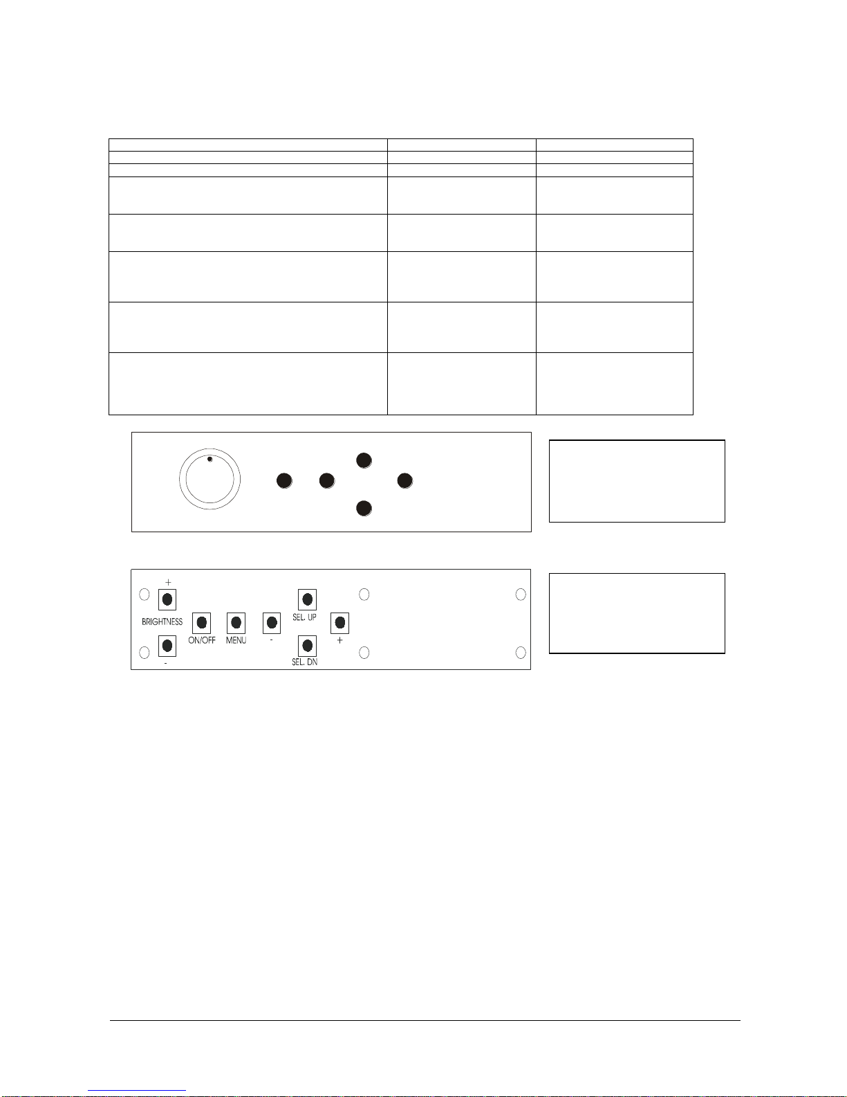
NOTE: By way of explanation the following refers to a set of sample buttons that may be obtained as an option. In addition to
power on/off and connection for backlight brightness the controller provides an On Screen Display of certain functions which are
controlled by 5 momentary type buttons (analog VR type) or 8 momentary type buttons (digital type):
Controls
Analog VR type
Digital type
On/Off – turns controller board power on
VR toggle switch
On/Off button
Brightness – controls backlight brightness
Rotary VR
Brightness +/- buttons
Menu
Turns OSD menu On or Off (it will auto time off)
Menu button
Menu button
Select up
Moves the selector to the previous level function
(up)
SEL UP
SEL UP
Select down
Moves the selector to the next level function
(down)
Confirm the OSD selection
SEL DN
SEL DN
+
Increase the OSD parameter values
Moves the selector to next function (forward)
+
+
-
Decrease the OSD parameter values
Moves the selector to previous function
(backward)
-
-
ON/Off/Brightness
SEL UP
SEL DN
+
-
Menu
Analog VR type
Digital type
12V / 24VDC power input :
Digital 10K Type OSD switch
mount uses
P/N 416100520-3 or up
12V / 24VDC power input :
Analog 10K VR Type OSD
switch mount uses
P/N 410680550-3 or up
Specifications subject to change without notice
© Digital View Ltd – Ver 1.0 August 24, 2017 (SVX-4096-VW_manual.doc) Page 9 of 52
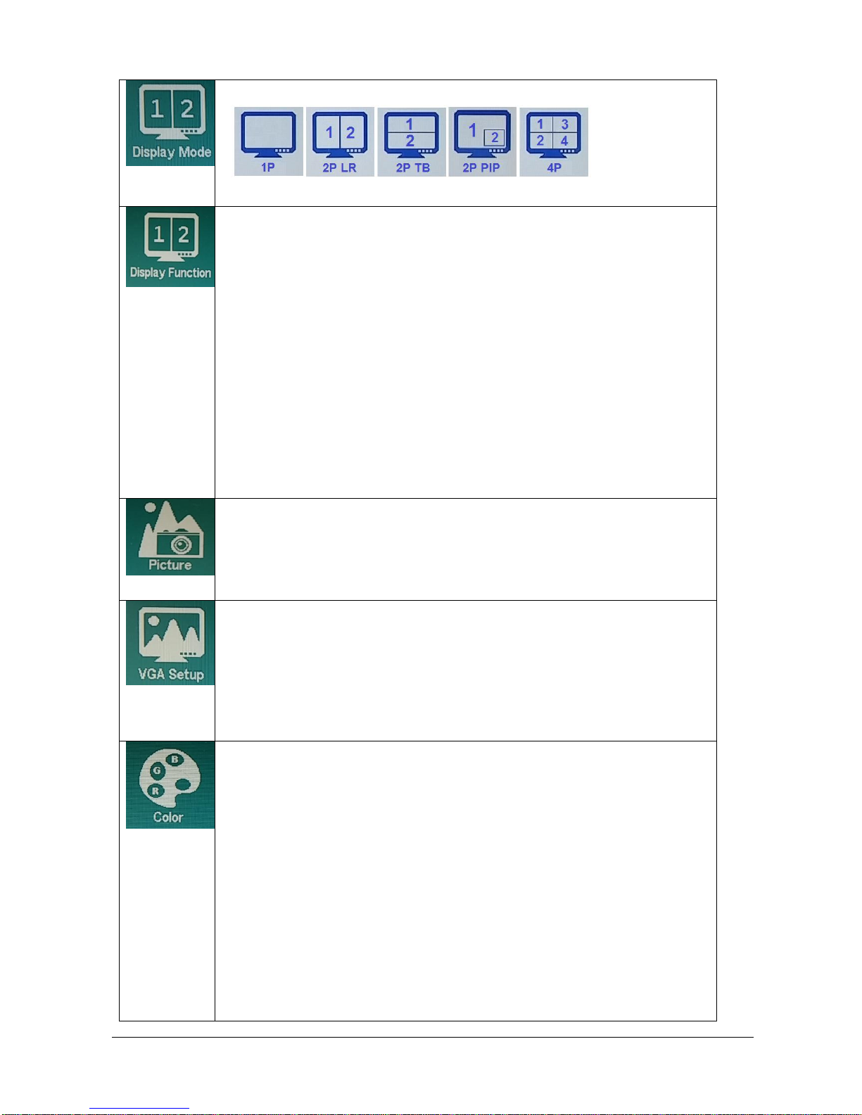
OSD functions
Display Mode:
[Default]
Display Function:
1P: Disp Rotate : 0 [Default]
90
180
270
2P LR: Input Swap
2P TB: Input Swap
2P PIP: PIP Position : Top-left
Top-right
Bottom-left
Bottom-right [Default]
PIP Transparency : [0 - 10] [Default 0]
PIP Size : [0 - 10] [Default 10]
Input Swap
Picture:
Backlight [0-100] [Default 100]
Brightness [0-100] [Default 50]
Contrast [0-100] [Default 50]
Sharpness [0-4] [Default 2]
VGA Setup:
Auto Adjust
H Position [0-100] [Default 50]
V Position [0-100] [Default 50]
Clock [0-100] [Default 50]
Phase [0-100] [Default 0]
Color Gain : Set
Reset
Color:
Gamma : 1.8
2.0
2.2 [Default]
2.4
Temperature: 9300
7500
6500 [Default]
5800
3200
sRGB
User : R [0-255]
G [0-255]
B [0-255]
Color Effect: Standard [Default]
Game
Movie
Photo
Vivid
Specifications subject to change without notice
© Digital View Ltd – Ver 1.0 August 24, 2017 (SVX-4096-VW_manual.doc) Page 10 of 52
User: R:
Hue [0-100]
Sat [0-100]
Y:
Hue [0-100]
Sat [0-100]
G:
Hue [0-100]
Sat [0-100]
C:
Hue [0-100]
Sat [0-100]
B:
Hue [0-100]
Sat [0-100]
M:
Hue [0-100]
Sat [0-100]
Hue: [0-100] [Default 50]
Saturation [0-100] [Default 50]
Advanced:
Aspect Ratio: Full [Default]
16:9
4:3
5:4
1:1
Over Scan: ON [Default]
OFF
Over Drive: ONOFF: ON
OFF [Default]
OD Gain [0-100] [Default 50]
Communication: RS-232 [Default]
Network
Auto Source Seek: OFF
ON [Default]
Hot Key: Hot Key 1 (< | >) : Input
Backlight
Brightness
Contrast
Sharpness
Hue
Saturation
Aspect Ratio
Display Mode
Input Swap
PIP Size
Auto Adjust
Volume
No Function [Default]
Hot Key: Hot Key 1 (Up | Dn) : Input
Backlight
Brightness
Contrast
Sharpness
Hue
Saturation
Aspect Ratio
Display Mode
Input Swap
PIP Size
Auto Adjust
Volume
No Function [Default]
Specifications subject to change without notice
© Digital View Ltd – Ver 1.0 August 24, 2017 (SVX-4096-VW_manual.doc) Page 11 of 52
Power Save: OFF
ON [Default]
Default Power: OFF
ON [Default]
Input:
(For all display modes: 1P/ 2R LR / 2P TB / 2P PIP / 4P)
A0 : VGA
D0 : DP
D1 : HDMI
D2 : HDMI
D4 : DVI
Audio:
Volume [0-100] [Default 50]
Mute: ON
OFF [Default]
Audio Source (1P) : Analog [Default]
Digital (region 1)
Audio Source (2P LR) : Analog [Default]
Digital (region 1) - Left
Digital (region 2) - Right
Audio Source (2P TB) : Analog [Default]
Digital (region 1) - Top
Digital (region 2) - Bottom
Audio Source (2P PIP) : Analog [Default]
Digital (region 1) - Main
Digital (region 2) - Sub
Audio Source (4P) : Analog [Default]
Digital (region 1) - Upper left
Digital (region 2) - Lower left
Digital (region 3) - Upper right
Digital (region 4) - Lower right
Other:
Reset
Menu Time [On, 11-60] [Default 11]
OSD H Position [0-100] [Default 50]
OSD V Position [0-100] [Default 50]
Language
Transparency [0-255] [Default 0]
Rotate: 0 [Default 0]
90
270
Border Width: [0-10] [Default 0]
Border Color: R [Default]
G
B
W
Video Wall: IR ID Assign : [0-254] [Default 0]
Specifications subject to change without notice
© Digital View Ltd – Ver 1.0 August 24, 2017 (SVX-4096-VW_manual.doc) Page 12 of 52
Wall On/Off : ON
: OFF [Default]
Wall Size : Wall Horizontal: [1-15] [Default 1]
: Wall Vertical: [1-15] [Default 1]
Wall Position : X Position: [0-14] [Default 0]
Wall Position : Y Position: [0-14] [Default 0]
Bezel On/Off : ON
: OFF [Default]
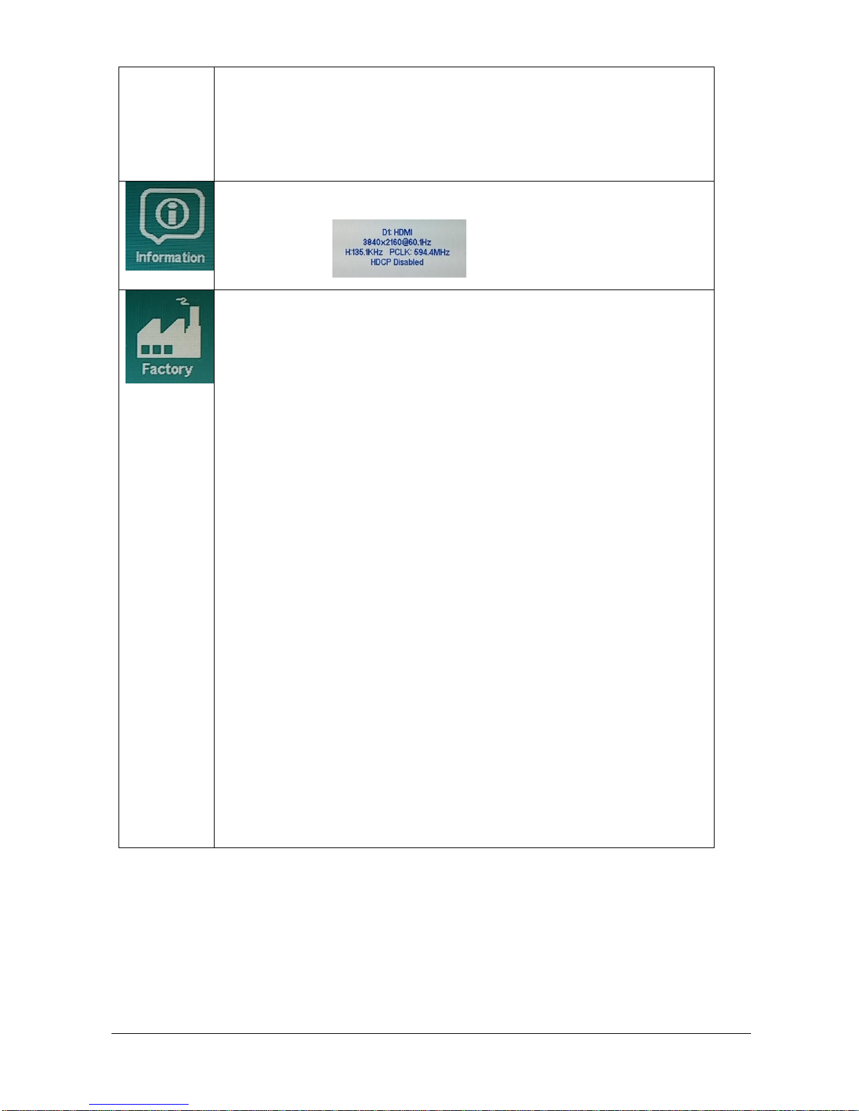
Information:
Factory:
Backlight Setup: Invert : OFF [Default]
ON
D/A / PWM : PWM [Default]
D/A
Frequency : [100Hz - 440Hz] [Default 160Hz]
Min. Level : [0% - 50%] [Default 5%]
VBy1 Setup : Pin 15 : Low [Default]
High
Pin 16 : Low [Default]
High
Pin 17 : Low [Default]
High
Pin 18 : Low [Default]
High
Pin 19 : Low [Default]
High
Pin 20 : Low [Default]
High
Pin 21 : Low [Default]
High
Pin 22 : Low [Default]
High
Pin 23 : Low [Default]
High
Pin 24 : Low [Default]
High
EDID Setup : Reset
Specifications subject to change without notice
© Digital View Ltd – Ver 1.0 August 24, 2017 (SVX-4096-VW_manual.doc) Page 13 of 52
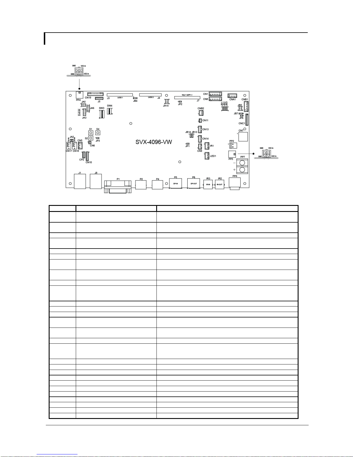
CONNECTORS, PINOUTS & JUMPERS
The various connectors are:
Summary: Connectors
Ref
Purpose
Description
CN1
Reserved for second RS-232 serial
control
JST 6-way, B6B-XH-A (Matching type : XHP-6)
CN5
Reserved for external temperature
sensor
JST 3-way, B3B-XH-A (Matching type : XHP-3)
CN6
Reserved for light sensor
DF13 2 ways (Matching type : DF13-2S-1.25C)
CN7
Audio board connector
Dual pin header 5x2, 0.1" pitch right angle
(Matching audio add-on board P/N 416940020-3)
CN8
RS-232 serial control
JST 6-way, B6B-XH-A (Matching type : XHP-6)
CN9
Ambient light sensor connector
JST 3-way, B3B-PH-K (Matching type : PHR-3)
CN10
Reserved for Fan & backlight power
monitoring connector
Hirose DF13-9P-1.25 DSA (Mating type : DF13-9S-1.25C)
CN11
SPDIF Audio output
JST B2B-ZR (Matching type : ZHR-2)
(Matching extend cable P/N 426007400-3)
CN13
Audio line in
JST B4B-ZR (Matching type : ZHR-4)
CN14
Audio line out
JST B4B-ZR (Matching type : ZHR-4)
(Use audio cable P/N 426451800-3 to connect with audio add-on bard
P/N 416940020-3)
CN17
Fan 1 connector
FAN connector, MKL-DP3-04W3-4
CN18
Fan 2 connector
FAN connector, MKL-DP3-04W3-4
CN19
Additional panel power output
JST B10B-PH-K (Matching type : PHR-10)
CNA1
Auxiliary power output
JST 4-way, B4B-XH-A (Matching type : XHP-4)
(Matching cable P/N 426040200-3)
CNB1
Backlight inverter
JST 5-way, B5B-XH-A (Matching type : XHP-5)
(Matching cable P/N 426058300-3)
CNB2
Backlight status input connector
JST 2 way, B2B-XH-A (Matching type : XHP-2)
CNC1
OSD control
Hirose DF13A-12P-1.25H (Mating type : DF13-12S-1.25C)
(Matching OSD switch mount cable P/N 426122200-3 (150mm) or
426122210-3 (250mm)
CP2
Reserved
Reserved
IR1
Infra-red sensor connector
JST 3-way, B3B-XH-A (Matching type : XHP-3)
IR2
Infra-red sensor output connector
RJ-11 connector
IR3
Infra-red sensor input connector
RJ-11 connector
J1
Ethernet
RJ-45 connector
J3
LVDS 1
JAE FI-RE51S-HF (Matching type : FI-RE51HL)
J4
LVDS 2
JAE FI-RE41S-HF (Matching type : FI-RE41HL)
J5
Panel power output
JS-1147A-08 Top 1.25mm (Matching type : JS-1146-08)
J7
V-by-One panel signal output
JAE FI-RE51S-HF (Matching type : FI-RE51HL)
J8
Ethernet
RJ-45 connector
LED1
Power LED connector
JST 3-way, B3B-XH-A (Matching type : XHP-3)
Specifications subject to change without notice
© Digital View Ltd – Ver 1.0 August 24, 2017 (SVX-4096-VW_manual.doc) Page 14 of 52
P1
DVI-I -- D4 / VGA -- A0
DVI-I connector
P2
HDMI (1.4) -- D3
HDMI connector
P4
HDMI (2.0) -- D1
HDMI connector
P5
Display Port (1.2) -- D0
Display Port connector
P6
Display Port Output
Display Port connector
PP2
Power input (alternative)
DC power Molex 2 pin 0.156” pitch
PP4
External panel power input
Molex 43045-0400 compatible
(Matching connector type : Molex 43025-0400 compatible)
(Matching power cable : P/N 426013710-3)
PP5
12V/24VDC input power
Molex 43045-0400 compatible
(Matching connector type : Molex 43025-0400 compatible)
(Matching power cable : P/N 426013710-3)
PP6
12V/24VDC input power
4-way PWR DIN Jack, MDP-JRM-04
PP7
12V/24VDC input power
Terminal block, ETB5302202002
S1
Reset button (for Ethernet function)
Tact switch button
S2
Reserved
Tact switch button
S4
Config Menu button (for Ethernet
function)
Tact switch button
SW3
Panel selection
8-way DIP Switch
SW4
Function selection
6-way DIP Switch

Specifications subject to change without notice
© Digital View Ltd – Ver 1.0 August 24, 2017 (SVX-4096-VW_manual.doc) Page 15 of 52
Summary: Jumpers setting
Ref
Purpose
Note
JA2
Fans Power select
24V Power input – Short 24V-IN, Open 12V-IN
12V Power input – Open 24V-IN, Short 12V-IN
JA3
Panel power voltage select
CAUTION: Incorrect setting can damage
panel
See panel voltage setting table 1
JA5
Panel power voltage select
CAUTION: Incorrect setting will cause panel
damage
See panel voltage setting table 1
JA6
Panel power voltage select
CAUTION: Incorrect setting will cause panel
damage
See panel voltage setting table 1
JA15
Panel power output control via J7 (pin 1-8)
and J6 (pin 5-9)
1-3, 2-4 = Enable panel power (3.3/5V) output on J7 and
J6
3-5, 4-6 = Enable panel power (10/12/18/24V) output on
J7 and J6
Open = Disable panel power output on J7 and J6
JB1
Backlight brightness voltage range
1-2 = 5V max
2-3 = 3.3V max
JB2
Backlight inverter on/off control – signal level
2-3 = On/Off control signal ‘High’ = +5V
1-2 = On/Off control signal ‘High’ = +3.3V
Open = On/Off control signal ‘High’ = Open collector
CAUTION: Incorrect setting can damage inverter.
JB3
Backlight inverter on/off control – polarity
1-2 = control signal ‘high’ = Backlight ON
2-3 = control signal ‘low’ = Backlight ON
JB4
Reserved for LVDS (J3) GPIO pins voltage
selection
1-2 = 3.3V
2-3 = 5V
JB5
Backlight control type selection
1-2 = VR/Digital switch mount control
3-4 = Analog backlight brightness - voltage range 0~5V
5-6 = PWM (Pulse Width Modulation) brightness
JB7
Backlight control voltage on CNB1 pin 4
(Function when JB5 sets 1-2 closed)
Open = For OSD switch mount control (Default)
1-2 = 0V
2-3 = 3.3V / 5V controlled by JB1
JB13
V-by-One / eDP selection on J7
1-2 = V-by-One
2-3 = eDP (1.1)
JB14
V-by-One / eDP selection on J7
1-2 = V-by-One
2-3 = eDP (1.1)
JP1
Factory use
Default Open
JP2
V-by-One power output configuration
1-2 = All pin 44 ~ pin 51 on J7 have power output
Open = Only the upper four pins have power output
(Refer to power output enabled/disabled on JA15. But
not applicable if JA15 is set to OPEN)
JP6
Input power control
Short = External switch control and fix the board ON
Open = Switch mount control
Specifications subject to change without notice
© Digital View Ltd – Ver 1.0 August 24, 2017 (SVX-4096-VW_manual.doc) Page 16 of 52
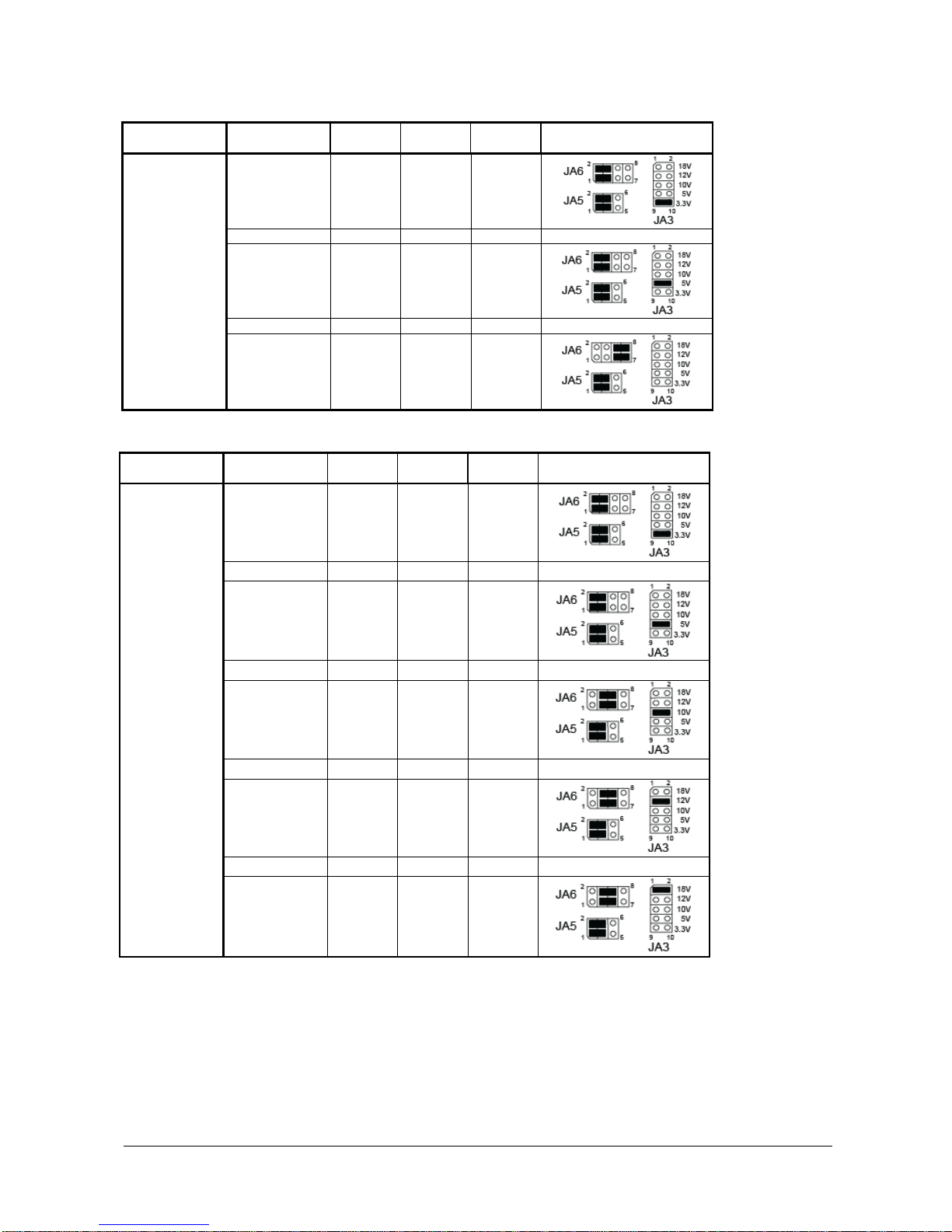
Table 1 : Panel voltage setting table :
Input voltage via
PP2/PP5
Panel Voltage
JA3
JA5 JA6
Jumper on board
12VDC
3.3V
3V3 closed
1-3 & 2-4
1-3 & 2-4
5V
5V closed
1-3 & 2-4
1-3 & 2-4
12V
OPEN
1-3 & 2-4
5-7 & 6-8
CAUTION: Incorrect setting can damage panel & controller
Input voltage via
PP2/PP5
Panel Voltage
JA3 JA5
JA6
Jumper on board
24VDC**
3.3V
3V3 closed
1-3 & 2-4
1-3 & 2-4
5V
5V closed
1-3 & 2-4
1-3 & 2-4
10V
10V closed
1-3 & 2-4
3-5 & 4-6
12V
12V closed
1-3 & 2-4
3-5 & 4-6
18V
18V closed
1-3 & 2-4
3-5 & 4-6
CAUTION: Incorrect setting can damage panel & controller
** Ensure that the backlight inverter supports 24V operation prior to connecting a 24VDC input. Because
CNA1 pin 1 and CNB1 pin 2 will output 24VDC if input 24VDC via PP5 or PP2.
 Loading...