

Digital View DD-1920-HDMI-EDPT Instructions Manual
HDMI, VIDEO INTERFACE CONTROLLER
FOR eDP PANEL
Model: DD-1920-HDMI-EDPT
Part number : 41766001X-3 or up
INSTRUCTIONS
CONTENTS
Page: 2. Introduction, How to Proceed, Usage Note, Disclaimer
3. System design – Diagram of a suggested system
4. Assembly notes – Important information about system elements
6. Connection & Operation – How to use the controller
10. Connectors, pinouts & jumpers – Essential connection information
18. Controller dimensions
19. Application notes
21. Troubleshooting
22. Specifications
23. Appendix I – Signal support modes table
24. Appendix II – RS-232 control protocols and command set
30. Appendix III – DV remote control unit work for DD-1920-HDMI-EDPT
31. Warranty, Caution & Limitation of Liability, Trademarks
32. Contact details
33. Revision History
It is essential that these instructions are read and understood before connecting or
powering up this controller.
Specifications subject to change without notice
© Digital View Ltd – Ver 1.1 29 Jan 2019 (DD-1920-HDMI-EDPT_manual.doc) Page 1 of 33

See at :
http://www.digitalview.com/csg
Introduction
Designed for LCD monitor and other flat panel display applications, the DD-1920-HDMI-EDPT is a feature rich interface
controller for :
TFT (active matrix) LCD panels of 1920x1080 resolutions in 60Hz with eDP panel interface.
Support true 8 bits panel
Support HDMI input.
HOW TO PROCEED
Ensure you have all parts & that they are correct, refer to:
• Connection diagram
Check controller switch & jumper settings (errors may damage the panel)
Prepare the signal sources
Connect the parts
Understand the operation & functions
IMPORTANT USAGE NOTE
This equipment is for use by developers and integrators, the manufacturer accepts no liability for damage or injury caused by
the use of this product. It is the responsibility of the developer, integrators or other user of this product to:
• Ensure that all necessary and appropriate safety measures are taken.
• Obtain suitable regulatory approvals as may be required.
• Check power settings to all component parts before connection.
DISCLAIMER
There is no implied or expressed warranty regarding this material.
Controller Solution Generator
Full web resource matching controllers & panels with connection diagrams for download.
• Connector reference (in following section)
• Assembly notes
Specifications subject to change without notice
© Digital View Ltd – Ver 1.1 29 Jan 2019 (DD-1920-HDMI-EDPT_manual.doc) Page 2 of 33
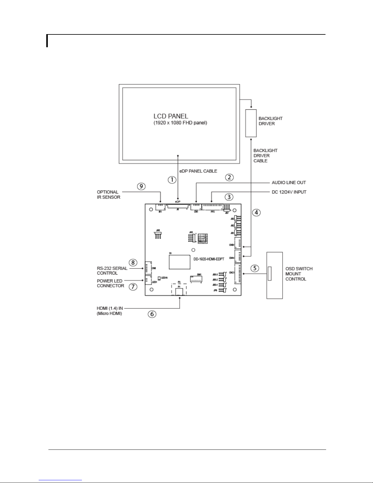
SYSTEM DESIGN
A typical LCD based display system utilizing this controller is likely to comprise the following:
Cable requires for connection:
1. eDP cable : Custom made
2. Audio line out cable : 426454900-3, 300mm
3. Power in cable : 426019600-3, 300mm
4. Backlight driver cable : Custom made
5. OSD switch mount cable : 426122900-3, 300mm
6. HDMI cable (Micro HDMI to Standard HDMI) : N/A
7. Power LED cable : 426032100-3, 300mm
8. CN8 extend cable : 426092400-3, 100mm
9. IR extend cable : 426032100-3, 300mm
Specifications subject to change without notice
© Digital View Ltd – Ver 1.1 29 Jan 2019 (DD-1920-HDMI-EDPT_manual.doc) Page 3 of 33

ASSEMBLY NOTES
This controller is designed for monitor and custom display projects using 1920x1080 resolution with eDP interface panels. The
following provides some guidelines for installation and preparation of a finished display solution.
Preparation: Before proceeding it is important to familiarize yourself with the parts making up the system and the various connectors,
mounting holes and general layout of the controller. As much as possible connectors have been labeled. Guides to connectors and
mounting holes are shown in the following relevant sections.
1. LCD Panel: This controller is designed for typical eDP interfaced panels with panel voltage 3.3V(4A), 5V(4A), 10V(4A) or 12V(4A).
Due to the variation between manufacturers of panels signal timing and other panel characteristics, factory setup and confirmation
should be obtained before connecting to a panel. (NOTE: Check panel power jumper settings before connection)
2. LCD Controller: Handle the controller with care as static charge may damage electronic components. Make sure correct jumper
to match the target LCD panel.
3. Panel cable: In order to provide a clean signal it is recommended that all eDP panel cables supplied by Digital View. Care should
be taken when placing the cables to avoid signal interference.
4. Inverter/Backlight driver: This will be required for the backlight of an LCD, some LCD panels have an inverter/backlight driver
built in. As LCD panels may have 1 or more backlight tubes and the power requirements for different panel backlights may vary it
is important to match the inverter/backlight driver in order to obtain optimum performance. See Application notes page 19 for
more information on connection.
5. Inverter/backlight cables: Different inverter/backlight models require different cables and different pin assignment. Make sure
correct cable pin out to match the inverter/backlight. Using wrong cable pin out may damage the inverter/backlight.
6. Function Controls: The following section discusses the controls required and the section on connectors provides the detail. The
controls are minimal: On/Off, Backlight Brightness (depends on inverter), OSD switch mount (5 momentary buttons) analog VR
type or (8 momentary buttons) digital type.
7. Function controls cable: The cables to the function switches should be of suitable quality and length so that impedance does
not affect performance. Generally lengths up to 1 meter (3 feet) should be acceptable.
8. Optional LED: The pin direction of the LED should be corrected for right color indication. Red color stands for standby. Green
colors stands for signal on. The status LED is an optional part only, can be unconnected.
9. Optional IR sensor: It is an optional part only, can be unconnected if not using IR remote control.
10. RS-232 control interface : Serial control via this interface port.
11. External panel power output : User for specific panel model.
12. Panel control signal : Use for specific panel model.
13. Backlight status input : 2 ways connector provides interface for connection with the specific panel type which support the panel
with backlight status monitoring function.
14. Micro HDMI input : Plug the HDMI cable to the Micro HDMI connector P1 on the controller board. (Standard HDMI (Type A)
connector P3 is a built option on request.)
15. Power Input: 12V/24VDC is required, this should be a regulated supply. It allows 12V (5A) or 24V (5A) via PP2 power input
connector. The power rating is depending on the panel and inverter used. Although the controller provides power regulation for
the LCD power, this does not relate to the power supplied to the backlight driver/inverter.
If an unregulated power supply is provided to an backlight driver/inverter, any fluctuations in power may affect operation,
performance and lifetime of the inverter and or backlight tubes.
•••• Power output: Note the controller has an overall 3Amp current limit and the current available from the auxiliary power output will
be dependent on the power input and other system requirements.
•••• Power Safety: Note that although only 12V / 24VDC is required as ‘power-in’ a backlight inverter for panel backlighting produces
significantly higher voltages (the inverter does not connect to the ground plane). We strongly advise appropriate insulation for all
circuitry.
•••• EMI: Shielding will be required for passing certain regulatory emissions tests. Also the choice of external Controller to PC signal
cable can affect the result.
•••• Ground: The various PCB mounting holes are connected to the ground plane.
•••• Servicing: The board is not user serviceable or repairable. Warranty does not cover user error in connecting up to the controller
and is invalidated by unauthorized modification or repairs.
Specifications subject to change without notice
© Digital View Ltd – Ver 1.1 29 Jan 2019 (DD-1920-HDMI-EDPT_manual.doc) Page 4 of 33

•••• Controller Mounting: It is recommended that a clearance of at least 10mm is provided above and 5mm below the controller
when mounted. Additionally consideration should be given to:
• Electrical insulation.
• Grounding.
• EMI shielding.
• Cable management. Note: It is important to keep panel signal cables apart from the inverter & backlight cables to prevent
signal interference.
• Heat & Ventilation: Heat generated from other sources, for example the backlight of a very high brightness panel may
generate significant heat which could adversely affect the controller.
• Other issues that may affect safety or performance.
•••• PC Graphics Output: A few guidelines:
• Signal quality is very important, if there is noise or instability in the PC graphics output this may result in visible noise on the
display.
• Refer to graphics modes table in specifications section for supported modes.
• Non-interlaced & interlaced video input is acceptable.
IMPORTANT: Please read the Application Notes section for more information.
Specifications subject to change without notice
© Digital View Ltd – Ver 1.1 29 Jan 2019 (DD-1920-HDMI-EDPT_manual.doc) Page 5 of 33

CONNECTION & OPERATION
CAUTION: Never connect or disconnect parts of the display system when the system is powered up as this may cause serious damage.
CONNECTION
Connection and usage is quite straight forward (it is useful to have the relevant connection diagram available at this time):
1. LCD panel & backlight driver: Connect the inverter/Backlight driver (if it is not built-in the panel) to the inverter/backlight
2. eDP interface panels: The controller board supports eDP interface FHD panel. Plug the eDP cable to J6. And make sure the
3. Inverter/Backlight driver: Plug the inverter/backlight cable to CNB1 and CNA1 (if necessary). Plug another end to the connector
4. Function switch & Controller: Plug the OSD switch mount cable to CNC1 on the controller board and another to the OSD switch
5. LED & Controller: Plug in a 3-way with dual color LED to connector LED1 on the controller board.
6. IR & Controller: Plug in a 3-way with IR sensor to connector IR1 on the controller board.
7. Jumpers & Inverter & Panel voltage: Particularly pay attention to the settings of JA3, JA6, JB2 and JB3. JB2 & JB3 are used
8. Input signal cable & Controller: Plug the corresponding signal input to the connector on the controller board.
9. Power supply & Controller: Plug the DC 12V/24V power in to the connector PP2.
10. Power on: Switch on the controller board and panel by using the OSD switch mount.
General:
• If you are using supplied cables & accessories, ensure they are correct for the model of panel and controller.
• If you are making your own cables & connectors refer carefully to both the panel & inverter specifications and the section in this
PC SETTINGS
The controller has been designed to take a very wide range of input signals however to optimize the PC’s graphics performance we
recommend choosing 60Hz vertical refresh rate – this will not cause screen flicker.
OPERATION
Once the system has been connected and switched on there are a number of functions available to adjust the display image as
summarized in the following sections. The settings chosen will be saved for each mode independently.
connector of the LCD panel.
matching panel timings and correct jumper settings (JA3 & JA6) by referring to the panel support table and jumper settings
table in page 12-14.
on the inverter/backlight of panel side.
mount.
for inverter control (read inverter specification and information on the jumper table to define the correct settings). JA3 & JA6
is used for panel voltage input (read panel specification and information on the jumper table to define the correct settings).
manual, “Connectors, Pinouts & Jumpers” to ensure the correct pin to pin wiring.
Specifications subject to change without notice
© Digital View Ltd – Ver 1.1 29 Jan 2019 (DD-1920-HDMI-EDPT_manual.doc) Page 6 of 33
•
LCD DISPLAY SYSTEM SETTINGS
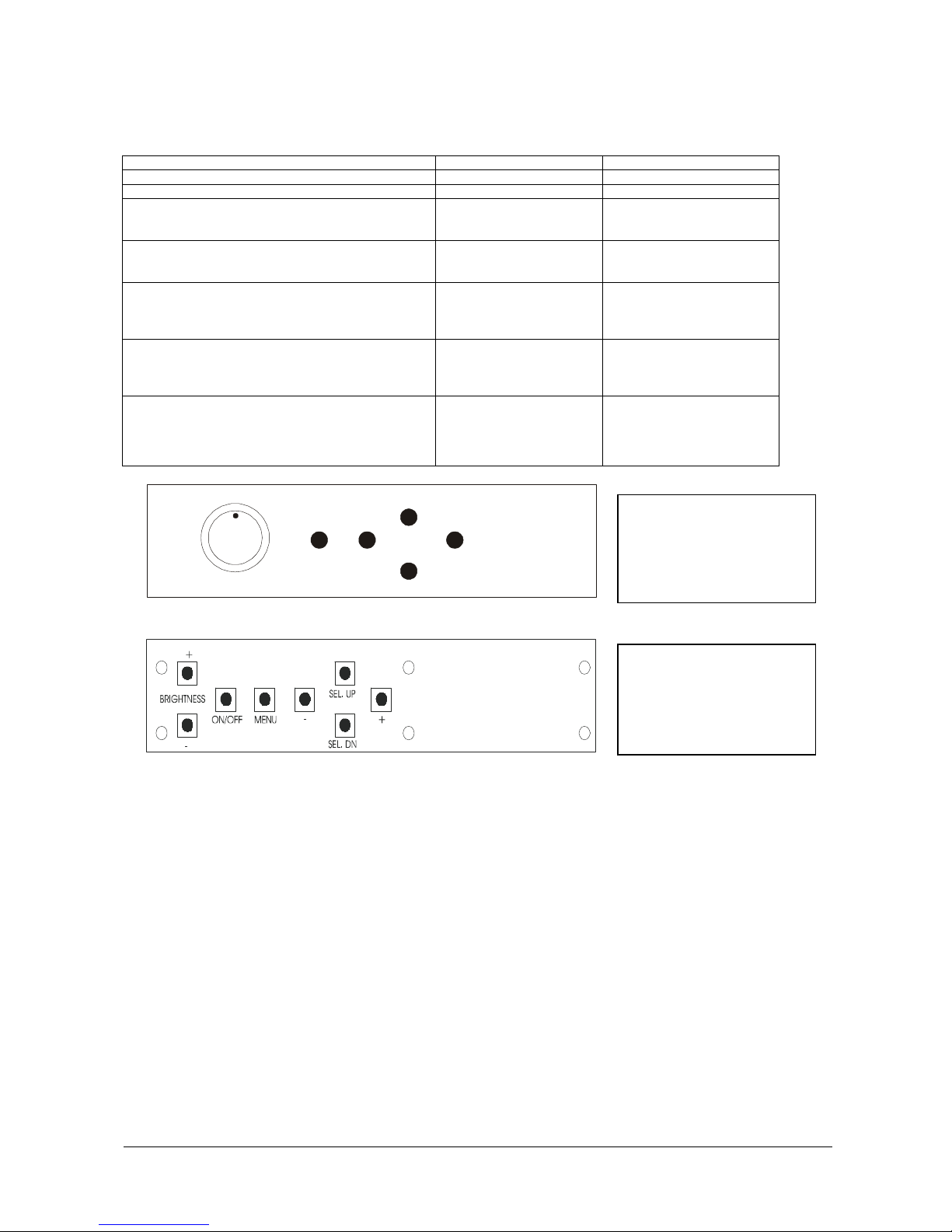
NOTE: By way of explanation the following refers to a set of sample buttons that may be obtained as an option. In addition to
power on/off and connection for backlight brightness the controller provides an On Screen Display of certain functions which are
controlled by 5 momentary type buttons (analog VR type) or 8 momentary type buttons (digital type):
Controls Analog VR type Digital type
On/Off – turns controller board power on VR toggle switch On/Off button
Brightness – controls backlight brightness Rotary VR Brightness +/- buttons
Menu
• Turns OSD menu On or Off (it will auto time off)
Select up
• Moves the selector to the previous level function
(up)
Select down
• Moves the selector to the next level function
(down)
Confirm the OSD selection
+
• Increase the OSD parameter values
• Moves the selector to next function (forward)
-
• Decrease the OSD parameter values
• Moves the selector to previous function
(backward)
Menu button Menu button
SEL UP SEL UP
SEL DN SEL DN
+ +
- -
ON/Off/Brightness
-
Menu
Analog VR type
Digital type
SEL UP
SEL DN
+
12V / 24VDC power input :
Analog 10K VR Type OSD
switch mount uses
P/N 410680550-3 or up
OSD cable: P/N 416122900-3
12V / 24VDC power input :
Digital 10K Type OSD switch
mount uses
P/N 416100520-3 or up
OSD cable: P/N 416122900-3
Specifications subject to change without notice
© Digital View Ltd – Ver 1.1 29 Jan 2019 (DD-1920-HDMI-EDPT_manual.doc) Page 7 of 33
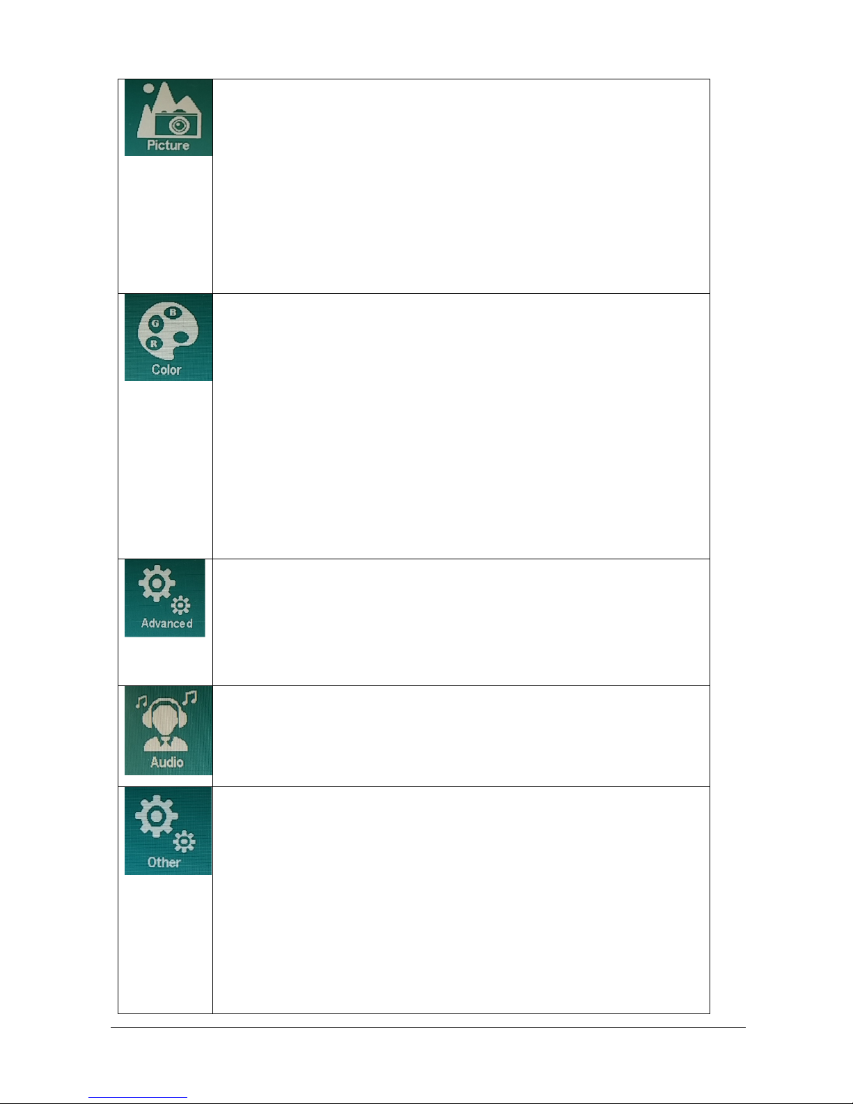
OSD functions
Specifications subject to change without notice
© Digital View Ltd – Ver 1.1 29 Jan 2019 (DD-1920-HDMI-EDPT_manual.doc) Page 8 of 33
Picture:
Brightness Brightness: [0-100] [Default 50]
Invert: OFF [Default]
ON
D/A / PWM: PWM [Default]
D/A
Frequency: [100Hz - 440Hz] [Default 240Hz]
Black level [0-100] [Default 50]
Contrast [0-100] [Default 50]
Sharpness [0-4] [Default 2]
Color:
Gamma : 1.8
2.0
2.2 [Default]
2.4
2.6
Temperature: 9300
7500
6500 [Default]
5000
sRGB
User : R [0-255]
G [0-255]
B [0-255]
Hue: [0-100] [Default 50]
Saturation [0-100] [Default 50]
Advanced:
Aspect Ratio: Full [Default]
16:9
4:3
5:4
Default Power: OFF
ON [Default]
Audio:
Volume [0-100] [Default 50]
Mute: ON
OFF [Default]
Other:
Reset
Menu Time [0 (Always On), 10-60] [Default 10]
OSD H Position [0-100] [Default 50]
OSD V Position [0-100] [Default 50]
Language [English] only
Transparency [0-255] [Default 0]
Rotate: 0 [Default 0]
90
270
180
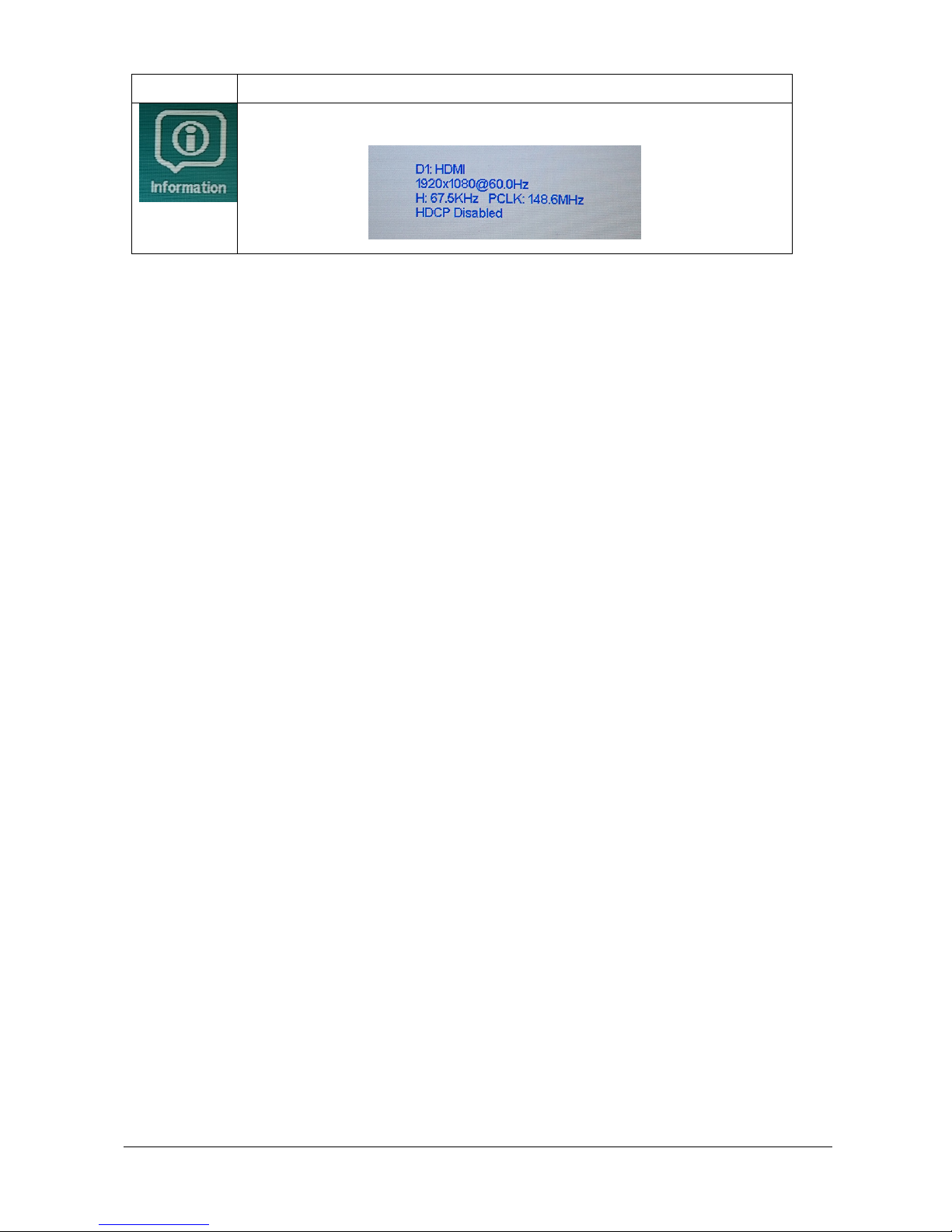
Information:
Specifications subject to change without notice
© Digital View Ltd – Ver 1.1 29 Jan 2019 (DD-1920-HDMI-EDPT_manual.doc) Page 9 of 33
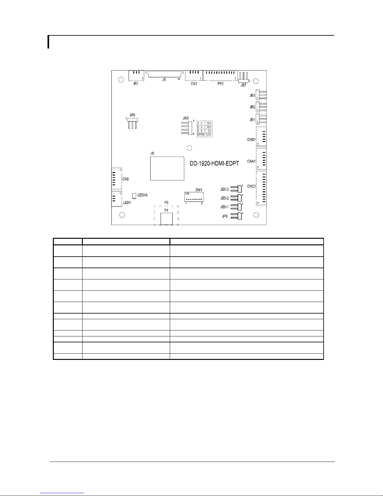
CONNECTORS, PINOUTS & JUMPERS
The various connectors are:
Summary: Connectors
Ref Purpose Description
CN1 Audio outut (Stereo) from HDMI 12513WR-04 or compatible (Matching type : Molex 51146-0400
CN8 RS-232 serial control 12513WR-06 or compatible (Matching type : Molex 51146-0600
CNA1 Auxiliary power output 12513WR-06 or compatible (Matching type : Molex 51146-0600
CNB1 Backlight inverter 12513WR-05 or compatible (Matching type : Molex 51146-0500
CNC1 OSD control 12513WR-12 or compatible (Matching type : Molex 51146-1200
IR1 Infra-red sensor connector 12513WR-03 or compatible (Matching type : Molex 51146-0300
J6 eDP connector I-PEX 20455-030E-12 (Matching type : I-PEX 20454-030T)
LED1 Power LED connector 12513WR-03 or compatible (Matching type : Molex 51146-0300
P1 HDMI in Micro HDMI connector (Type D)
P3 HDMI in (Build option) Standard HDMI connector (Type A)
PP2 Power input 12513WR-12 or compatible (Matching type : Molex 51146-1200
SW1 Panel selection 8-way DIP Switch
or compatible)
or compatible)
or compatible)
or compatible)
or compatible)
or compatible)
or compatible)
or compatible)
Specifications subject to change without notice
© Digital View Ltd – Ver 1.1 29 Jan 2019 (DD-1920-HDMI-EDPT_manual.doc) Page 10 of 33
 Loading...