

Digital View ALR-1920-120 Instructions Manual

HDMI, DISPLAY PORT INTERFACE CONTROLLER
FOR TFT PANEL
Model: ALR-1920-120
Part number : 41731003X-3 or up
INSTRUCTIONS
CONTENTS
Page: 2. Introduction, How to Proceed, Usage Note, Disclaimer
3. System design – Diagram of a suggested system
4. Assembly notes – Important information about system elements
6. Connection & Operation – How to use the controller
10. Connectors, pinouts & jumpers – Essential connection information
18. Controller dimensions
19. Application notes
20. Troubleshooting
21. Specifications
23. Appendix I – Mode Support Table
24. Appendix II – RS-232 control protocols
28. Appendix III – DDC/CI support at HDMI & Display port
29. Appendix IV – Mapping definition
33. Appendix V – DV remote control unit work for ALR-1920-120
34. Warranty, Caution & Limitation of Liability, Trademarks
35. Contact details
It is essential that these instructions are read and understood before connecting or
powering up this controller.
Page 2 of 35
Introduction
ALR-1920-120 is the controller board equipped with IE-1010 and ALR-1920 engine integrated. ALR-1920-120 is capable
to drive the panel up to 1920x1200 resolution and also supporting up to 120Hz panel. This controller supports HDMI
and Display Port input. And it will be the lower cost solution for 120Hz panel.
¾ TFT (active matrix) LCDs with LVDS interface of 1920x1200, 1920x1080, 1280x1024 resolution
¾ Computer video signals of WUXGA, UXGA, SXGA, XGA, SVGA, VGA standard
¾ Support HDMI, Display port input
¾ Support LVDS interface panel
¾ Support DDC/CI at HDMI & Display port.
Ordering information :
Controller Part number Ordering part number
ALR-1920-120 P/N 41731003X-3 P/N 4173100XX-3
HOW TO PROCEED
¾ Ensure you have all parts & that they are correct, refer to:
• Connection diagram (separate document for each panel)
• Connector reference (in following section)
• Assembly notes
¾ Check controller switch & jumper settings (errors may damage the panel)
¾ Prepare the signal source
¾ Connect the parts
¾ Understand the operation and functions (in following section)
IMPORTANT USAGE NOTE
This product is for use by system developers and integrators, the manufacturer accepts no liability for damage or
injury caused by the use of this product. It is the responsibility of the developer, integrators or other user of this
product to:
¾ Ensure that all necessary and appropriate safety measures are taken.
¾ Obtain suitable regulatory approvals as may be required.
¾ Check power settings to all component parts before connection.
¾ Understand the operation and connectivity requirements of this controller.
DISCLAIMER
There is no implied or expressed warranty regarding this material.
Controller Solution Generator
Full web resource matching controllers & panels with connection diagrams for download.
See at : http://www.digitalview.com/csg
Page 3 of 35
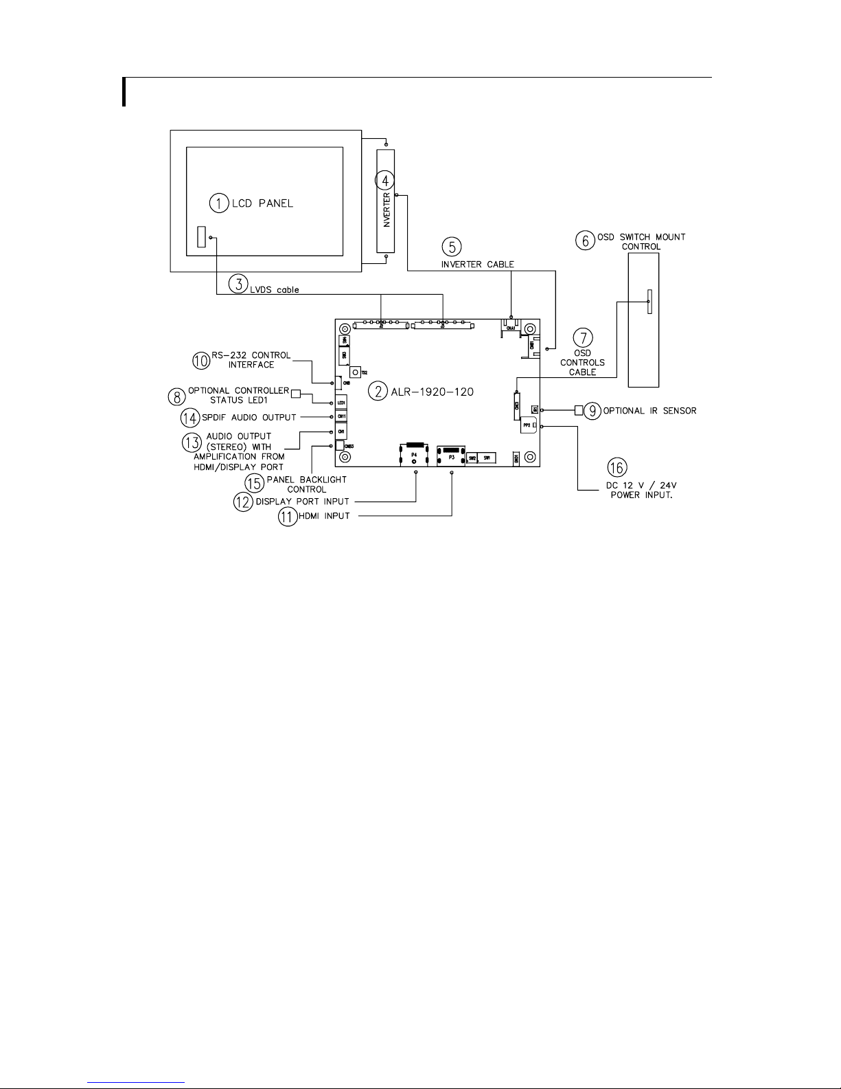
SYSTEM DESIGN
A typical LCD based display system utilising this controller is likely to comprise the following:
Summary:
1. LCD panel
2. LCD controller card, ALR-1920-120
3. LVDS cable
4. Inverter for backlight (if not built into LCD)
5. Inverter cable
6. OSD switch mount control
7. OSD controls cable
8. Optional Controller status LED1
9. Optional IR sensor
10. RS-232 control interface
11. HDMI input
12. Display Port Input
13. Audio output (Stereo) with amplication from HDMI / Display Port
14. SPDIF Audio output
15. Panel backlight control (for 120Hz panel used only)
16. Power input (12VDC / 24VDC)
Digital View offers a range of accessories such as listed above, to make up complete display solution.
Page 4 of 35
ASSEMBLY NOTES
ALR-1920-120 is the controller board equipped with IE-1010 and ALR-1920 engine integrated. ALR-1920-120 is capable to
drive the panel up to 1920x1200 resolution and also supporting up to 120Hz panel. This controller supports HDMI and Display
Port input. And it will be the lower cost solution for 120Hz panel.
Preparation: Before proceeding it is important to familiarize yourself with the parts making up the system and the various
connectors, mounting holes and general layout of the controller. As much as possible connectors have been labeled. Guides
to connectors and mounting holes are shown in the following relevant sections.
1. LCD Panel: This controller is designed for typical LVDS interface TFT panels with panel voltage 3.3V or 5V or 12V or 18V
LVDS interface. Due to the variation between manufacturers of signal timing and other panel characteristics factory setup
and confirmation should be obtained before connecting to a panel. (NOTE: Check panel power jumper settings before
connection)
2. Controller card: Handle the controller card with care as static charge may damage electronic components.
3. LVDS signal cable : In order to provide a clean signal it is recommended that LVDS signal cables are no longer than
46cm (18 inches). If loose wire cabling is utilized these can be made into a harness with cable ties. Care should be taken
when placing the cables to avoid signal interference. Additionally it may be necessary in some systems to add ferrite cores
to the cables to minimize signal noise.
4. Inverter: This will be required for the backlight of an LCD, some LCD panels have an inverter built in. As panels may have
1 or more backlight tubes and the power requirements for different panel models backlights may vary it is important to
match the inverter in order to obtain optimum performance. See page 19 for the Application notes “Inverter connection
section for more informations.
5. Inverter Cables: Different inverter models require different cables and different pin assignment. Make sure correct cable
pin out to match the inverter. Using wrong cable pin out may damage the inverter.
6. OSD switch mount controls: The following section discusses the controls required and the section on connectors
provides the detail. The controls are minimal: On/Off, Backlight Brightness (depends on inverter), OSD (5 momentary
buttons) analog VR type or (8 momentary buttons) digital type.
7. OSD switch mount controls cable: The cables to the function switches should be of suitable quality and length so that
impedance does not affect performance. Generally lengths up to 1 metre (3 feet) should be acceptable.
8. Controller status LED (Optional) : This LED indicates the controller status. The pin direction of the LED should be
corrected for right colour indication. Red colour stands for standby. Green colours stands for signal on. The status LED
is an optional part only, can be unconnected.
Controller LED status (LED1) :
State LED color
No signal & backlight off RED
No signal & backlight on ORANGE
With signal & backlight on GREEN
9. IR sensor: It is an optional part only, can be unconnected if not using IR remote control. See Appendix VI for button
definition.
10. RS-232 control interface : Firmware upgrade and serial control via this interface port. See Appendix II for the RS-232
serial control protocols.
11. HDMI input : Support HDMI 1.3 input up to 1080p/WUXGA resolution. Plug the HDMI cable to the connector P3 on
the controller board. This port support DDC/CI (See Appendix III in details).
12. Display Port Cable : Support single-link Display Port 1.1a. Plug the Display Port cable to the connector P4 on
the controller board. This port support DDC/CI (See Appendix III in details).
13. Audio output (Stereo) with amplication from HDMI / Display Port : This port support Stereo audio output from the HDMI
/ Display Port audio source inputted. This port has the same audio path output from J1. It requires to select the audio port
“Speakers” via OSD menu under “Sound” > “Output” OSD menu page.
14. SPDIF Audio output : This port support SPDIF audio output from the HDMI / Display Port audio source inputted. It
requires to select the audio port “SPDIF” via OSD menu under “Sound” > “Output” OSD menu page.
15. Panel Backlight control : Used for 120Hz panel connection only.
16. Power Input: 12V / 24V DC is required, this should be a regulated supply. Although the controller provides power
regulation for the LCD power this does not relate to the power supplied to the backlight inverter. If an unregulated power supply
is provided to an inverter any fluctuations in power may affect operation, performance and lifetime of the inverter and or
backlight tubes. 24VDC input is required when the panel output voltage is 18VDC. Please refer to page 11-12 for proper jumper
settings.
• Power Safety: Note that although only 12VDC / 24VDC is supplied as ‘power-in’ a backlight inverter for panel backlighting
produces significantly higher voltages (the inverter does not connect to the ground plane). We strongly advise appropriate
insulation for all circuitry.

Page 5 of 35
• EMI: Shielding will be required for passing certain regulatory emissions tests. Also the choice of external Controller to PC
signal cable can affect the result.
• Ground: The various PCB mounting holes are connected to the ground plane.
• Servicing: The board is not user serviceable or repairable. Warranty does not cover user error in connecting up to the
controller and is invalidated by unauthorized modification or repairs.
• Controller Mounting: It is recommended that a clearance of at least 10mm is provided above and 5mm below the
controller when mounted. Additionally consideration should be given to:
• Electrical insulation.
• Grounding.
• EMI shielding.
• Cable management. Note: It is important to keep panel signal cables apart from the inverter & backlight cables to
prevent signal interference.
• Heat & Ventilation: Heat generated from other sources, for example the backlight of a very high brightness panel may
generate significant heat which could adversely affect the controller.
• Other issues that may affect safety or performance.
IMPORTANT: Please read the Application Notes section for more information.
Page 6 of 35
CONNECTION & OPERATION
CAUTION: Never connect or disconnect parts of the display system when the system is powered up as this may cause serious
damage.
CONNECTION
Connection and usage is quite straight forward (it is useful to have the relevant connection diagram available at this time):
1. LCD panel & Inverter: Connect the inverter (if it is not built-in the panel) to the CCFT lead connector of the LCD
panel.
2. LVDS type panels: Plug the LVDS signal cable direct to J2 and/or J3 (if necessary). Insert the panel end of the
cable to the LCD panel connector.
3. Inverter & Controller: Plug the inverter cable to CNB1 and CNA1 (if necessary). Plug another end to the connector
on the inverter.
4. Function switch & Controller: Plug the OSD switch mount cable to CNC1 on the controller board and another to
the OSD switch mount.
5. LED 1 : Plug in a 3-way with dual colour LED to connector LED1 on the controller board for indicating the controller
status.
6. IR & Controller: Plug in a 3-way with IR sensor to connector IR1 on the controller board.
7. Jumpers : Check all jumpers are set correctly. Details referring the connection diagram at
http://www.digitalview.com/controllers/csg.php
8. Jumpers & Inverter & Panel voltage: Particularly pay attention to the settings of JA3, JA6, JB2, JB3. JB2 & JB3
are used for inverter control (read inverter specification and information on the jumper table to define the correct
settings). JA3 & JA6 are used for panel voltage input (read panel specification and information on the jumper table to
define the correct settings).
10. HDMI cable : Plug the HDMI cable to the connector P3 on the controller board.
12. Display port cable : Plug the Display port cable to connector P4 on the controller board.
13. Audio output connector / SPDIF audio connector : audio output port CN1 support audio output (stereo) from the
HDMI / Display Port and CN11 support audio SPDIF audio output from HDMI / Display Port audio source inputted. It
requires to select the audio port “Speakers” / “SPDIF” via OSD menu under “Sound” > “Output” OSD menu page.
14. Power supply & Controller: Plug the DC 12V / 24V power in to the connector PP2. You can consider to use
DigitalView mating power cable P/N 426013800-3, 160mm. Please read the jumper table in page 11-12 to define the
correct settings. Otherwise it may break down the panel.
15. Power on: Switch on the controller board and panel by using the OSD switch mount.
CAUTION: Never connect or disconnect parts of the display system when the system is powered up as this may cause serious
damage.
On board LED status :
Power status on LED2 :
State LED color
Power on state Green
Power status on LED3 :
State LED color
Panel Power on state Green
Controller LED status (LED1A) :
State LED color
No signal & backlight off RED
No signal & backlight on ORANGE
With signal & backlight on GREEN
General:
• If you are using supplied cables & accessories, ensure they are correct for the model of panel and controller.
• If you are making your own cables & connectors refer carefully to both the panel & inverter specifications and the section
in this manual, “Connectors, Pinouts & Jumpers” to ensure the correct pin to pin wiring.
OPERATION
Once the system has been connected and switched on there are a number of functions available to adjust the display
image as summarized in the following sections. The settings chosen will be saved for each mode independently.
Page 7 of 35
BUTTONS & DEMO MODES
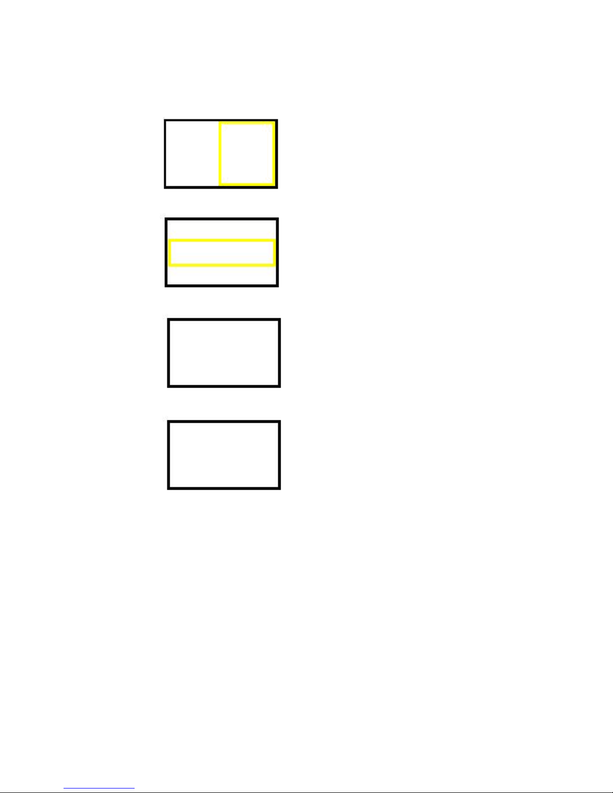
• Button switch – TS2 : Push TS2 to cycle between the 4 different demo modes (This function is activated when JP3 sets
OPEN only)
Mode 1 (default) = RIGHT demo mode, right side of screen with smoothed motion while left side without (a box with yellow
border appear on RIGHT hand side of screen);
Mode 2 = CENTRE demo mode, centre part of screen with smoothed motion while other areas without (a box with yellow border
appear in the CENTRE of the screen);
Mode 3 = whole screen without smoothed motion
Mode 4 = whole screen with smoothed motion
The controller will not memorize the demo mode after you power cycle the controller. It will resume back to mode 1 always.
* This function will not activate in static text mode (i.e : SW3 position 8 sets ON).
Page 8 of 35
LCD DISPLAY SYSTEM SETTINGS
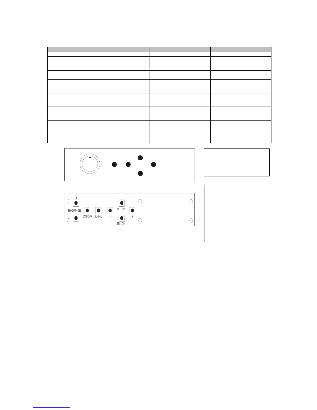
NOTE: By way of explanation the following refers to a set of sample buttons that may be obtained as an option. In addition
to power on/off and connection for backlight brightness the controller provides an On Screen Display of certain functions
which are controlled by 5 momentary type buttons (analog VR type) or 8 momentary type buttons (digital type):
Controls Analog VR type Digital type
On/Off – turns controller board power on VR toggle switch On/Off button
Brightness – controls backlight brightness Rotary VR Brightness +/- buttons
Menu – turns OSD menu On or Off (it will auto time
off) (Function with signal input only)
Menu button Menu button
Select – Select function / Confirm
(under OSD menu on state)
SEL DN SEL DN
Move up to select individual RGB color level OSD
page
(under OSD menu on state)
SEL UP SEL UP
+ – increase the setting / moves the selector to the
next function
(under OSD menu on state)
+ +
- - decrease the setting / moves the selector to the
previous function
(under OSD menu on state)
- -
Reset to Factory Defaults Press and hold SEL DN
button, then power on the
controller
Press and hold SEL DN button,
then power on the controller
Switch to next input source
(under OSD menu off state)
+ +
ON/Off/Brightness
SEL UP
SEL DN
+
-
Menu
Analog VR type
Digital type
12V / 24VDC power input :
Analog 10K VR Type OSD
switch mount uses
P/N 410680550-3 or up
12V / 24VDC power input :
Digital 10K Type OSD
switch mount uses
P/N 416100520-3 or up
12VDC power input :
Digital 10K Type OSD
switch mount uses
P/N 416100510-3
Page 9 of 35
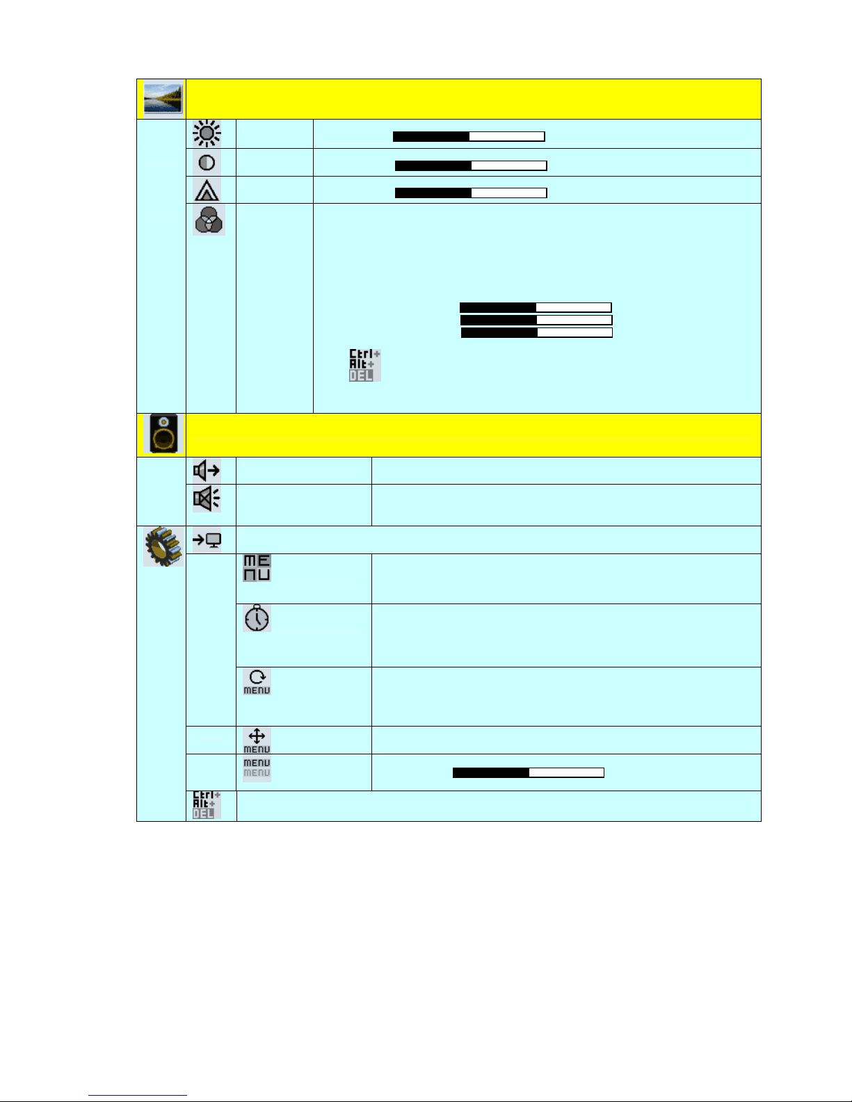
OSD Functions
Image
Brightness
Increase/decrease brightness level.
Press – or + (- + ) Total : 100 steps
Contrast
Increase/decrease contrast level.
Press – or + (- + ) Total : 100 steps
Sharpness
Increase/decrease sharpness level.
Press – or + (- + ) Total : 8 steps
Color
Color temp4 (Adjust the warmness of the image displayed. The higher temperature the
coolest image looks like. The lower temperature the warmest image looks like.)
4200k
5000k
6500k
7500k
9300k
User 4
R Press – or + (- + ) Total : 100 steps
G Press – or + (- + ) Total : 100 steps
B Press – or + (- + ) Total : 100 steps
Reset
Gamma (0.4/0.6/1.0/1.6/2.2)
Sound
Mute
Mute
Output
Select audio output port
Speakers : via CN1 connector
SPDIF : via CN11 connector
System4
Input : Select the input video signal
Display Port
DVI/HDMI
Autoscan : Enable the Auto source seek function
Timer : OSD Timeout in seconds
3 sec
6 sec
12 sec
Always On
Rotation : OSD menu rotation in degree
0
90
180
270
Position : Adjust OSD menu position
Transparency : Set OSD transparency
Press – or + (- + ) Total : 100 steps
Reset : Load factory default settings.
Press down on OSD keypad to factory reset
[Firmware version : V0.02.00 / V1.02.00 or up]
Items marked 4 have sub menus.
Exit the OSD menu to save the setting chosen
Page 10 of 35
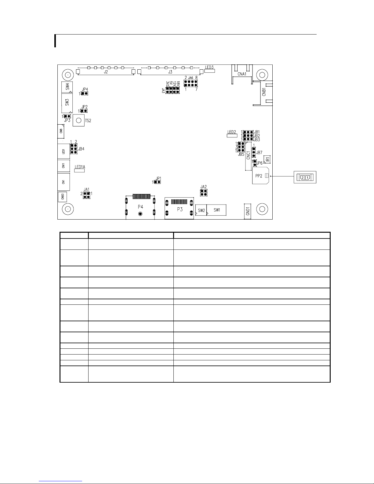
CONNECTORS, PINOUTS & JUMPERS
The various connectors are:
Summary: Connectors
Ref Purpose Description
CN1 Audio output (Stereo) with amplication
from HDMI / Display port
JST 4-way, S4B-ZR-SM4A (Mating type : ZHR-4)
(Matching connection cable P/N 426685400-3)
CN8 Serial control Molex 53261-0671, 6 ways 1.25mm pitch
(Mating type : Molex 51021-0600)
(Matching connection cable P/N 426171800-3)
CN11 SPDIF Audio Output JST 2-way, S2B-ZR-SM4A (Mating type : ZHR-2)
(Matching connection cable P/N 426007400-3)
CNA1 Auxiliary power output JST 4-way, S4B-XH-A (Mating type : XHP-4)
(Matching cable P/N 426040200-3)
CNB1 Backlight inverter JST 5-way, S5B-XH-A (Mating type : XHP-5)
(Matching cable P/N 426058300-3)
CNB3 Panel backlight control JST 2-way, B2B-XH-A (Matching type : XHP-2)
CNC1 OSD controls Hirose DF13A-12P-1.25H (Mating type : DF13-12S-1.25C)
(Matching OSD switch mount cable P/N 426122200-3 (150mm) or
426122210-3 (250mm)
IR1 Infra-Red sensor connector Molex 53261-0371, 3 way 1.25mm pitch (Mating type : 51021-0300)
(Matching connection cable P/N 426031500-3)
LED1 Dual color LED connector for controller
status
JST 3-way, S3B-ZR-SM4A (Mating type : ZHR-3)
(Matching connection cable P/N 426031400-3)
J2 LVDS panel signal output 1 JAE FI-RE41S-HF (Mating type : JAE FI-RE41HL)
J3 LVDS panel signal output 2 JAE FI-RE51S-HF (Mating type : JAE FI-RE51HL)
P3 HDMI signal input HDMI connector (Type A)
P4 Display Port input Display port connector
PP2 Power input Molex 43650-0200 compatible (Mating type : Molex 43645-0200
compatible)
(Matching power cable : P/N 426013800-3, 160mm)

Page 11 of 35
Summary: Jumpers setting
Ref Purpose Note
JA1 On board +1V logic power enable 1-3 & 2-4 closed, factory set, do not remove
JA2 On board +5V logic power enable 1-2 & 3-4 closed, factory set, do not remove
JA3 Panel power voltage select See panel voltage setting table 1
CAUTION: Incorrect setting will cause panel damage
JA6 Panel power voltage select See panel voltage setting table 1
CAUTION: Incorrect setting will cause panel damage
JB1 Backlight brightness voltage range 1-2 closed = 3.3V max
2-3 closed = 5V max
JB2 Backlight inverter on/off control – signal level 1-2 = On/Off control signal ‘High’ = +3.3V
2-3 = On/Off control signal ‘High’ = +5V
Open = On/Off control signal ‘High’ = Open collector
CAUTION: Incorrect setting can damage inverter.
JB3 Backlight inverter on/off control – polarity 1-2 = control signal ‘high’ = CCFT ON
2-3 = control signal ‘low’ = CCFT ON
JB4 Reserved for firmware upgrade 1-3 & 2-4 closed = Firmware upgrade on U10
3-5 & 4-6 closed = Firmware upgrade on U15
JB5 Backlight control type selection 1-2 = VR/Digital switch mount control
3-4 = Analog backlight brightness control via RS-232
command (0xe0) – voltage range 0~5V
5-6 = PWM
JB7 Backlight brightness orientation 1-2 = Normal backlight brightness
3-4 = Invert for the backlight brightness
Activate when JB5 sets 1-2 closed only.
JP1 Reserved Reserved for internal programming use (Always 1-2
closed)
JP2 Reserved for firmware upgrade Short = Firmware upgrade on U15
Open = Default
JP3 Demo mode selection Short = Disable demo mode
Open = Enable demo mode
JP4 Internal use Internal use
JP6 Input power control Short = External switch control
Open = Switch mount control
SW1 Panel selection See table below
SW2 Panel selection See table below
Table 1 : Panel voltage setting table :
Input voltage via
PP2 Panel Voltage JA3 JA6 Jumper on board
3.3V 3V3 closed 1-3 & 2-4
5V 5V closed 1-3 & 2-4
12VDC
12V OPEN 5-7 & 6-8
CAUTION: Incorrect setting can damage panel & controller
 Loading...