

digitalview ALR-1400 Instructions Manual
PC, DVI INTERFACE CONTROLLER
FOR TFT PANEL
Model: ALR-1400
Part number : 41710003X/4X-3 or up
INSTRUCTIONS
CONTENTS
Page: 2. Revision history
3. Introduction, How to Proceed, Usage Note, Disclaimer
4. System design – Diagram of a suggested system
5. Assembly notes – Important information about system elements
7. Connection & Operation – How to use the controller
10. Connectors, pinouts & jumpers – Essential connection information
20. Controller dimensions
21. Application notes
23. Troubleshooting
24. Specifications
25. Appendix I – Graphic Mode Support Table
26. Appendix II – RS-232 control protocols
30. Appendix III – Mapping definition
32. Appendix IV – Auto Color Gain
33. Warranty, Caution & Limitation of Liability, Trademarks
34. Contact details
It is essential that these instructions are read and understood before connecting or
powering up this controller.
Specifications subject to change without notice
© Digital View Ltd – Doc Ver 2.01: 8 July, 2016 Page
1 of 34
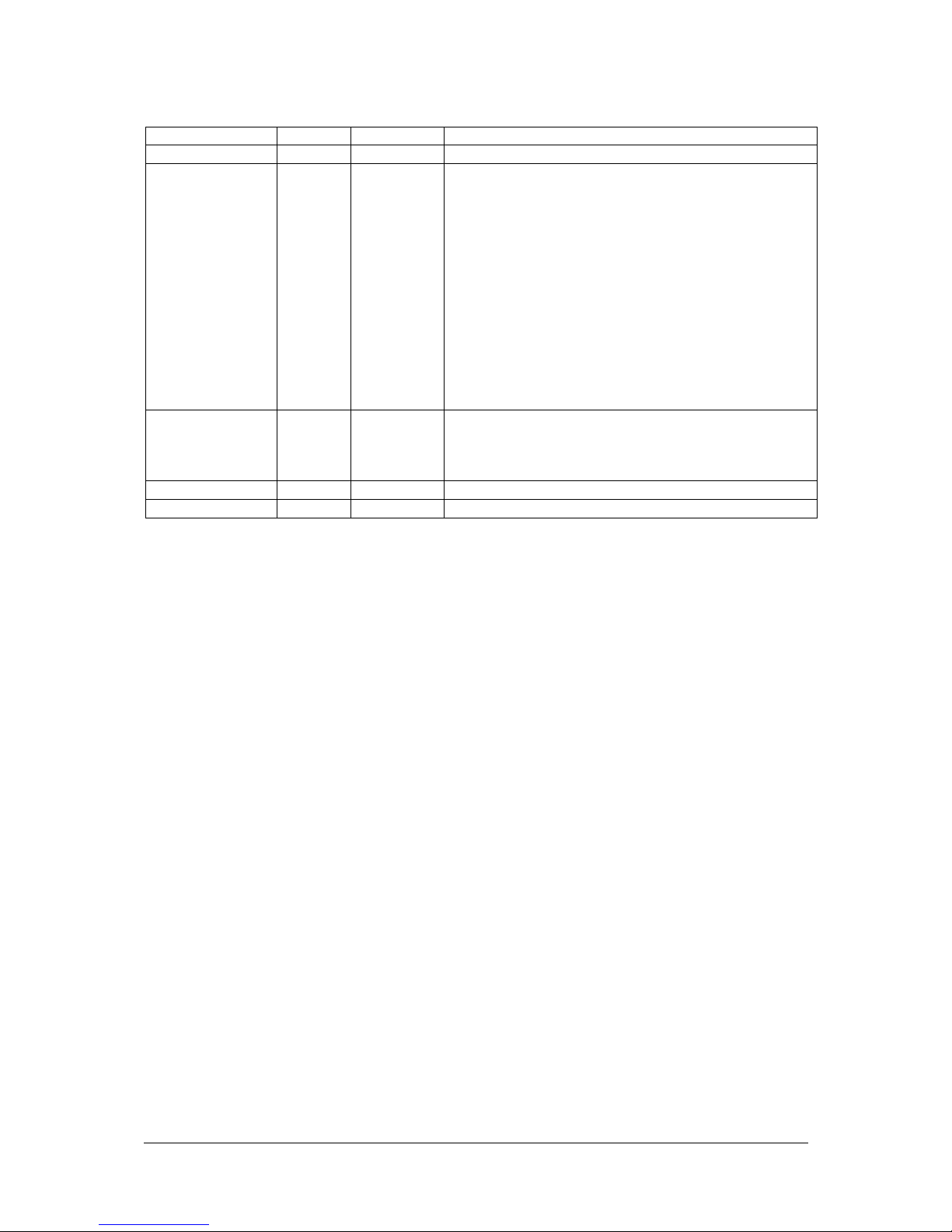
Revision History
Date Rev No. Page Summary
10 Sept 2015 1.00 All Features added for up to P/N 417100042-3
4 March 2016 2.00 8
8 July 2016 2.01 2
11, 18
14
27
27-28
Add feature done on V1.97.00 firmware to
implement the direct access key for Backlight
Brightness increase & decrease.
Revised the connector type used on CN8, CNA1,
CNB2 & CNC1 on the document.
Add more panel support implemented start from
V1.97.00 firmware.
Add new RS-232 command for "Sharpness",
"OSD menu timeout", "Gamma" & "Wide screen
mode selection" done start from V1.97.00
firmware.
Move the "Revision History" section to page 2
for better presentation.
Revised the range of Backlight Brightness
Control RS-232 command (0xe0)
Specifications subject to change without notice
© Digital View Ltd – Doc Ver 2.01: 8 July, 2016 Page
2 of 34
Introduction
Designed for LCD monitor and other flat panel display applications, the ALR-1400 controller provides easy to use
interface controller for:
TFT (active matrix) LCDs with LVDS interface of 1400x900, 1366x768, 1280x1024, 1280x800, 1280x768, 1024x768,
1024x600, 800x600, 800x480, 640x480, 480x234 resolution;
Computer video signals of SXGA, XGA, SVGA, VGA standard
Support LVDS or TTL interface panel
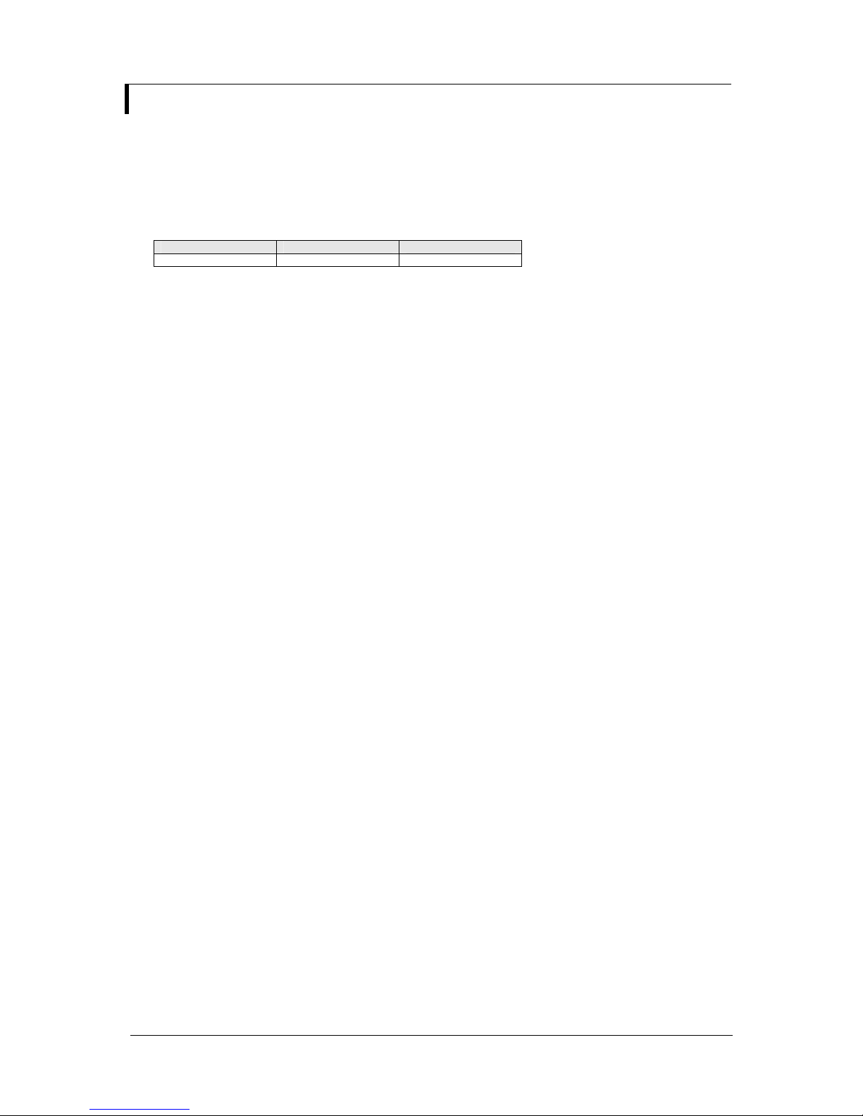
Ordering information :
Controller Part number Ordering part number
ALR-1400 P/N 41710004X-3 P/N 4171000XX-3
HOW TO PROCEED
Ensure you have all parts & that they are correct, refer to:
• Connection diagram (separate document for each panel)
• Connector reference (in following section)
• Assembly notes
Check controller switch & jumper settings (errors may damage the panel)
Prepare the PC
Connect the parts
Understand the operation and functions (in following section)
IMPORTANT USAGE NOTE
This product is for use by system developers and integrators, the manufacturer accepts no liability for damage or
injury caused by the use of this product. It is the responsibility of the developer, integrators or other user of this
product to:
Ensure that all necessary and appropriate safety measures are taken.
Obtain suitable regulatory approvals as may be required.
Check power settings to all component parts before connection.
Understand the operation and connectivity requirements of this controller.
DISCLAIMER
There is no implied or expressed warranty regarding this material.
Specifications subject to change without notice
© Digital View Ltd – Doc Ver 2.01: 8 July, 2016 Page
3 of 34
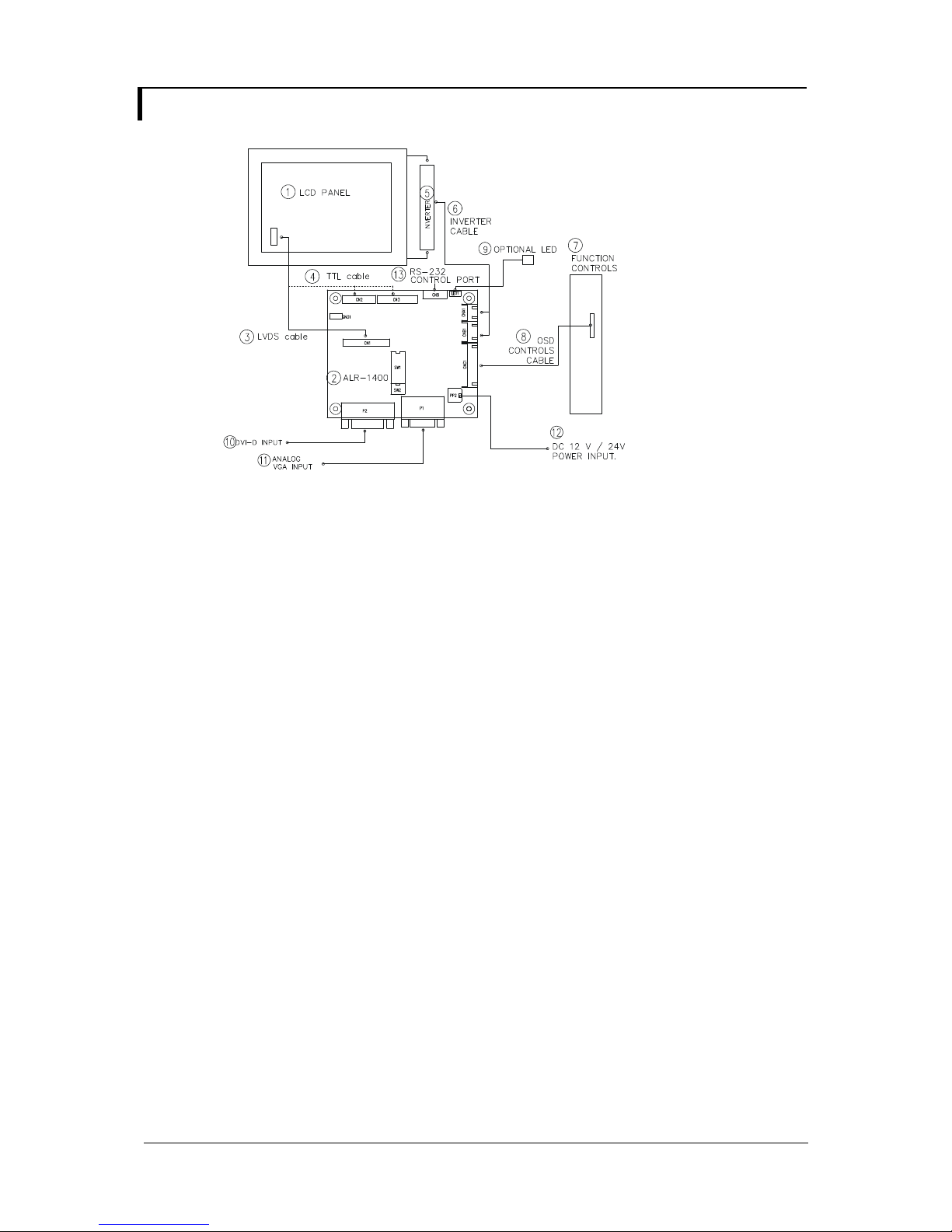
SYSTEM DESIGN
A typical LCD based display system utilising this controller is likely to comprise the following:
Summary:
1. LCD panel
2. LCD controller card, ALR-1400
3. LVDS cable (for connection with LVDS panel)
4. TTL cable (for connection with TTL panel)
5. Inverter for CCFT backlight (if not built into LCD)
6. Inverter cable
7. Function controls
8. Function controls cable
9. Status LED
10. DVI-D input
11. Analog VGA input
12. Power input (12VDC / 24VDC)
13. RS-232 control port
Digital View offers a range of accessories such as listed above, to make up complete display solution.
Specifications subject to change without notice
© Digital View Ltd – Doc Ver 2.01: 8 July, 2016 Page
4 of 34

ASSEMBLY NOTES
This controller is designed for monitor and custom display projects using 1440x900, 1366 x 768, 1280 x 1024, 1280 x 800,
1280 x 768 or 1024 x 768, 1024 x 600, 800 x 600, 800 x 480, 640 x 480 or 480 x 234 resolution TFT panels with a VGA, SVGA,
XGA, SXGA signal input. The following provides some guidelines for installation and preparation of a finished display solution.
Preparation: Before proceeding it is important to familiarize yourself with the parts making up the system and the various
connectors, mounting holes and general layout of the controller. As much as possible connectors have been labeled. Guides
to connectors and mounting holes are shown in the following relevant sections.
1. LCD Panel: This controller is designed for typical LVDS or TTL interface TFT panels with panel voltage 3.3V or 5V or 12V
or 18V LVDS interface. Due to the variation between manufacturers of signal timing and other panel characteristics
factory setup and confirmation should be obtained before connecting to a panel. (NOTE: Check panel power jumper
settings before connection)
2. Controller card: Handle the controller card with care as static charge may damage electronic components.
3. LVDS signal cable : In order to provide a clean signal it is recommended that LVDS signal cables are no longer than
46cm (18 inches). If loose wire cabling is utilized these can be made into a harness with cable ties. Care should be
taken when placing the cables to avoid signal interference. Additionally it may be necessary in some systems to add
ferrite cores to the cables to minimize signal noise.
4. TTL signal cable: In order to provide a clean signal it is recommended that LCD signal cables are no longer than 33cm
(13 inches). If loose wire cabling is utilized these can be made into a harness with cable ties. Care should be taken when
placing the cables to avoid signal interference. Additionally it may be necessary in some systems to add ferrite cores to
the cables to minimize signal noise.
5. Inverter: This will be required for the backlight of an LCD, some LCD panels have an inverter built in. As panels may
have 1 or more backlight tubes and the power requirements for different panel models backlights may vary it is important
to match the inverter in order to obtain optimum performance. See page 15 for the Application notes “Inverter connection
section for more informations.
6. Inverter Cables: Different inverter models require different cables and different pin assignment. Make sure correct cable
pin out to match the inverter. Using wrong cable pin out may damage the inverter.
7. Function Controls: The following section discusses the controls required and the section on connectors provides the
detail. The controls are minimal: On/Off, Backlight Brightness (depends on inverter), OSD (5 momentary buttons) analog
VR type or (8 momentary buttons) digital type.
8. Function controls cable: The cables to the function switches should be of suitable quality and length so that impedance
does not affect performance. Generally lengths up to 1 metre (3 feet) should be acceptable.
9. DVI-D Input Cable : Plug the DVI-D cable to the connector P2 on the controller board
10. Analog VGA Input Cable: As this may affect regulatory emission test results and the quality of the signal to the
•••• Power Input: 12V / 24V DC is required, this should be a regulated supply. Although the controller provides power
24VDC input is required when the panel output voltage is 18VDC. Please refer to page 10-11 for proper jumper settings.
•••• Power Safety: Note that although only 12VDC / 24VDC is supplied as ‘power-in’ a backlight inverter for panel backlighting
•••• EMI: Shielding will be required for passing certain regulatory emissions tests. Also the choice of external Controller to PC
•••• Ground: The various PCB mounting holes are connected to the ground plane.
•••• Servicing: The board is not user serviceable or repairable. Warranty does not cover user error in connecting up to the
•••• Controller Mounting: It is recommended that a clearance of at least 10mm is provided above and 5mm below the
Specifications subject to change without notice
© Digital View Ltd – Doc Ver 2.01: 8 July, 2016 Page
controller, a suitably shielded cable should be utilized.
regulation for the LCD power this does not relate to the power supplied to the backlight inverter. If an unregulated power
supply is provided to an inverter any fluctuations in power may affect operation, performance and lifetime of the inverter
and or backlight tubes.
produces significantly higher voltages (the inverter does not connect to the ground plane). We strongly advise
appropriate insulation for all circuitry.
signal cable can affect the result.
controller and is invalidated by unauthorized modification or repairs.
controller when mounted. Additionally consideration should be given to:
• Electrical insulation.
• Grounding.
• EMI shielding.
• Cable management. Note: It is important to keep panel signal cables apart from the inverter & backlight cables to
prevent signal interference.
• Heat & Ventilation: Heat generated from other sources, for example the backlight of a very high brightness panel
may generate significant heat which could adversely affect the controller.
5 of 34

• Other issues that may affect safety or performance.
•••• PC Graphics Output: A few guidelines:
• Signal quality is very important, if there is noise or instability in the PC graphics output this may result in visible noise
on the display.
• Refer to graphics modes table in specifications section for supported modes.
• Non-interlaced & interlaced video input is acceptable.
IMPORTANT: Please read the Application Notes section for more information.
Specifications subject to change without notice
© Digital View Ltd – Doc Ver 2.01: 8 July, 2016 Page
6 of 34
CONNECTION & OPERATION
CAUTION: Never connect or disconnect parts of the display system when the system is powered up as this may cause serious
damage.
CONNECTION
Connection and usage is quite straight forward (it is useful to have the relevant connection diagram available at this time):
1. LCD panel & Inverter: Connect the inverter (if it is not built-in the panel) to the CCFT lead connector of the LCD
2. LVDS type panels: Plug the LVDS signal cable direct to CN1 (if necessary). Insert the panel end of the cable to the
LCD panel connector.
3. TTL type panels: Plug the signal cables direct to CN2 or CN3. Plug the other end of cables to the LCD connector
board (if connector board is required, otherwise the signal can be direct plug to the LCD panel
connector). Then plug the board connector to the LCD panel connector.
4. Inverter & Controller: Plug the inverter cable to CNB1 and CNA1 (if necessary). Plug another end to the connector
on the inverter.
5. Function switch & Controller: Plug the OSD switch mount cable to CNC1 on the controller board and another to
the OSD switch mount.
6. LED & Controller: Plug in a 3-way with dual colour LED to connector LED1 on the controller board.
7. Jumpers : Check all jumpers are set correctly. Details referring the connection diagram at
http://www.digitalview.com/controllers/csg.php
8. Jumpers & Inverter & Panel voltage: Particularly pay attention to the settings of JA3, JA6, JB2, JB3. JB2 & JB3
9. DVI cable : Plug the DVI-D cable to the connector P2 on the controller board.
10. VGA cable & Controller: Plug the VGA cable to the connector P1 on the controller board.
12. Power supply & Controller: Plug the DC 12V / 24V power in to the connector PP2. You can consider to use
13. Power on: Switch on the controller board and panel by using the OSD switch mount.
CAUTION: Never connect or disconnect parts of the display system when the system is powered up as this may cause serious
damage.
LED status :
General:
• If you are using supplied cables & accessories, ensure they are correct for the model of panel and controller.
• If you are making your own cables & connectors refer carefully to both the panel & inverter specifications and the section
PC SETTINGS
The controller has been designed to take a very wide range of input signals however to optimize the PC’s graphics
performance we recommend choosing 60Hz vertical refresh rate – this will not cause screen flicker.
OPERATION
Once the system has been connected and switched on there are a number of functions available to adjust the display
image as summarized in the following sections. The settings chosen will be saved for each mode independently.
panel.
are used for inverter control (read inverter specification and information on the jumper table to define the correct
settings). JA3 & JA6 are used for panel voltage input (read panel specification and information on the jumper table
to define the correct settings).
DigitalView mating power cable P/N 426013800-3, 160mm.
State LED color
No signal & backlight off RED
No signal & backlight on ORANGE
With signal & backlight on GREEN
in this manual, “Connectors, Pinouts & Jumpers” to ensure the correct pin to pin wiring.
Specifications subject to change without notice
© Digital View Ltd – Doc Ver 2.01: 8 July, 2016 Page
7 of 34
LCD DISPLAY SYSTEM SETTINGS
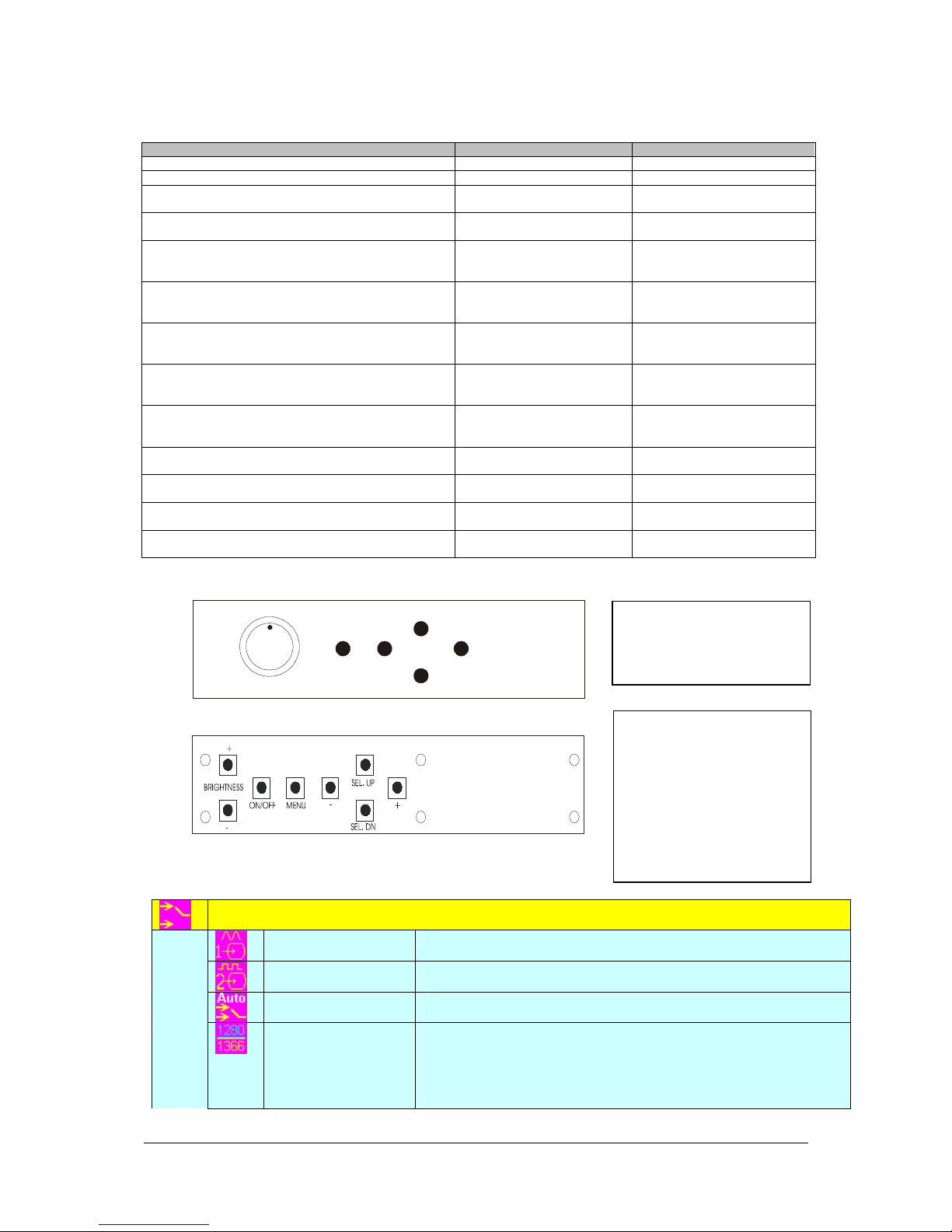
NOTE: By way of explanation the following refers to a set of sample buttons that may be obtained as an option. In
addition to power on/off and connection for backlight brightness the controller provides an On Screen Display of certain
functions which are controlled by 5 momentary type buttons (analog VR type) or 8 momentary type buttons (digital type):
Controls Analog VR type Digital type
On/Off – turns controller board power on VR toggle switch On/Off button
Brightness – controls backlight brightness Rotary VR Brightness +/- buttons
Menu – turns OSD menu On or Off (it will auto time
off) (Function with signal input only)
Select – Select function / Confirm
(under OSD menu on state)
Move up to select individual RGB color level OSD
page
(under OSD menu on state)
+ – increase the setting / moves the selector to the
next function
(under OSD menu on state)
- - decrease the setting / moves the selector to the
previous function
(under OSD menu on state)
Reset to Factory Defaults Press and hold SEL DN
Lock OSD menu
(Function with signal input only)
Direct access key for Brightness level increase
(under OSD menu off state)
Direct access key for Brightness level decrease
(under OSD menu off state)
Direct access key for Backlight Brightness increase#
(under OSD menu off state)
Direct access key for Backlight Brightness decrease#
(under OSD menu off state)
# - Only effective on V1.97.00 or up version.
Menu button Menu button
SEL DN SEL DN
SEL UP SEL UP
+ +
- -
button, then power on the
controller
Press and hold MENU button
for 15 seconds to enable /
disable lock of the OSD menu
+ +
- -
SEL UP SEL UP
SEL DN SEL DN
SEL UP
Press and hold SEL DN button,
then power on the controller
Press and hold MENU button for
15 seconds to enable / disable
lock of the OSD menu
12V / 24VDC power input :
Analog 10K VR Type OSD
ON/Off/Brightness
Menu
-
+
SEL DN
switch mount uses
P/N 410680550-3 or up
Analog VR type
12V / 24VDC power input :
Digital 10K Type OSD
switch mount uses
P/N 416100520-3 or up
12VDC power input :
Digital 10K Type OSD
Digital type
OSD Functions
Specifications subject to change without notice
© Digital View Ltd – Doc Ver 2.01: 8 July, 2016 Page
Select input source
Input source 1
Input source 2
Auto Source Seek
Wide screen mode
information display*
Select input source to Analog RGB
Select input source to DVI
ON – Auto source select always enable
OFF – Disable auto source select function
Select the input mode (1280 / 1360 / 1366 / 1368) to recognize and display the
correct input signal information display on the OSD menu.
1280 : 1280x768
1360 : 1360x768
1366 :1366x768
1368 : 1368x768
switch mount uses
P/N 416100510-3
8 of 34
Yes
No
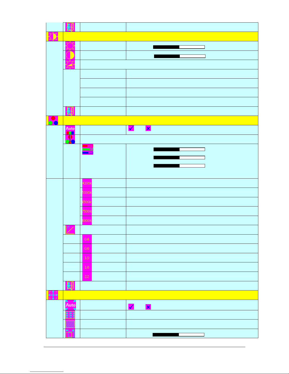
Brightness and Contrast
Exit
Exit the OSD menu and save the settings
Color
Brightness
Contrast
Backlight4444
Invert
Control
Frequency
B/L
Exit
Auto RGB Calibration*
Color Temperature 4444 (Adjust the warmness of the image displayed. The higher temperature the
coolest image looks like. The lower temperature the warmest image looks like.)
Increase/decrease brightness level.
Press – or + (- + ) Total : 256 steps
Increase/decrease panel contrast level.
Press – or + (- + ) Total : 192 steps
B/L Invert : Invert for the backlight brightness
D/A / PWM : Selection for voltage level dimming control / PW M dimming control
Backlight frequency 100 ~ 440Hz in a step of 20
Backlight brightness adjustment
Exit the OSD menu and save the settings
Yes
No ( Auto Color Calibration [See appendix IV])
Adjust red color level
Press – or + (- +) Total :128 steps
Adjust green color level
Press – or + (- +) Total : 128 steps
Adjust blue color level
Press – or + (- +) Total : 128 steps
Press SEL UP/DN button to select item
Set the color temperature to 4200K
Set the color temperature to 5000K
Set the color temperature to 6500K
Set the color temperature to 7500K
Set the color temperature to 9300K
Gamma adjustment4444
Exit
Position
Specifications subject to change without notice
© Digital View Ltd – Doc Ver 2.01: 8 July, 2016 Page
Autosetup*
Frequency*
Phase*
Image Horizontal
Position*
Adjust Gamma settings (0.4 / 0.6 / 1.0 / 1.6 / 2.2)
Select Gamma to 0.4
Select Gamma to 0.6
Select Gamma to 1.0
Select Gamma to 1.6
Select Gamma to 2.2
Exit the OSD menu and save the settings
Auto adjust the positions, phase, frequency
Adjust the image horizontal size
Fine tune the data sampling position (adjust image quality)
Use +/- to move the image horizontally
Press – or + (- + )
9 of 34
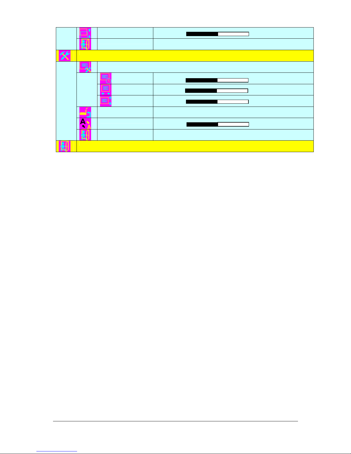
Utilities
Image Vertical
Position*
Exit
Use +/- to move the image vertically
Press – or + (- + )
Exit the OSD menu
Exit the OSD menu
* Function in ARGB mode only
Items marked 4 have sub menus.
Exit the OSD menu to save the setting chosen
OSD setting 4444
Load Factory Default
Sharpness
Exit
OSD Timeout : 0 / 10 / 20 / 30 / 40 / 50 / 60 seconds (Always on when set to 0)
Press – or + (- + )
OSD menu horizontal position
Press – or + (- + )
OSD menu vertical position
Press – or + (- + )
Initialize the setting stored in non-volatile memory
Adjust sharpness level
Press – or + (- + ) Total : 7 steps
Exit the OSD menu
[Firmware version : V1.91 or up]
Specifications subject to change without notice
© Digital View Ltd – Doc Ver 2.01: 8 July, 2016 Page
10 of 34
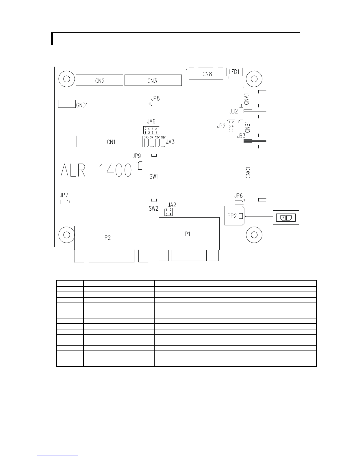
CONNECTORS, PINOUTS & JUMPERS
The various connectors are:
Summary: Connectors
Ref Purpose Description
CN1 LVDS panel signal Hirose 40-pin, DF13-40DP-1.25DSA (Mating type : DF13-40DS-1.25C)
CN2 TTL panel signal Hirose 40-pin, DF20G-40DP-1V (Mating type : DF20A-40DS-1C)
CN3 TTL Panel signal Hirose 50-pin, DF20G-50DP-1V (Mating type : DF20A-50DS-1C)
CN8 Serial control (for firmware
programming or RS-232 control
use only)
CNA1 Auxiliary power output JST 4-way, S4B-XH-A or compatible (Mating type : XHP-4 or compatible)
CNB1 Backlight inverter JST 5-way, S5B-XH-A or compatible (Mating type : XHP-5 or compatible)
CNC1 Function controls JST 12-way, S12B-XH-A or compatible (Mating type : XHP-12 or compatible)
LED1 Dual color LED connector Header pin 3x1
P1 ARGB signal input DB-15 way high density 3 row
P2 DVI-D signal input DVI-D connector
PP2 Power input Molex 43650-0200 or compatible (Mating type : Molex 43645-0200
Specifications subject to change without notice
© Digital View Ltd – Doc Ver 2.01: 8 July, 2016 Page
JST 6-way, B6B-XH-A or compatible (Mating type : XHP-6 or compatible)
compatible)
(Matching power cable : P/N 426013800-3)
11 of 34
 Loading...