

Digital Projection TITAN 1080p 330 3D L Ultra Contrast, TITAN 1080p 660, TITAN 1080p 660 3D Ultra Contrast User Manual
Page 1

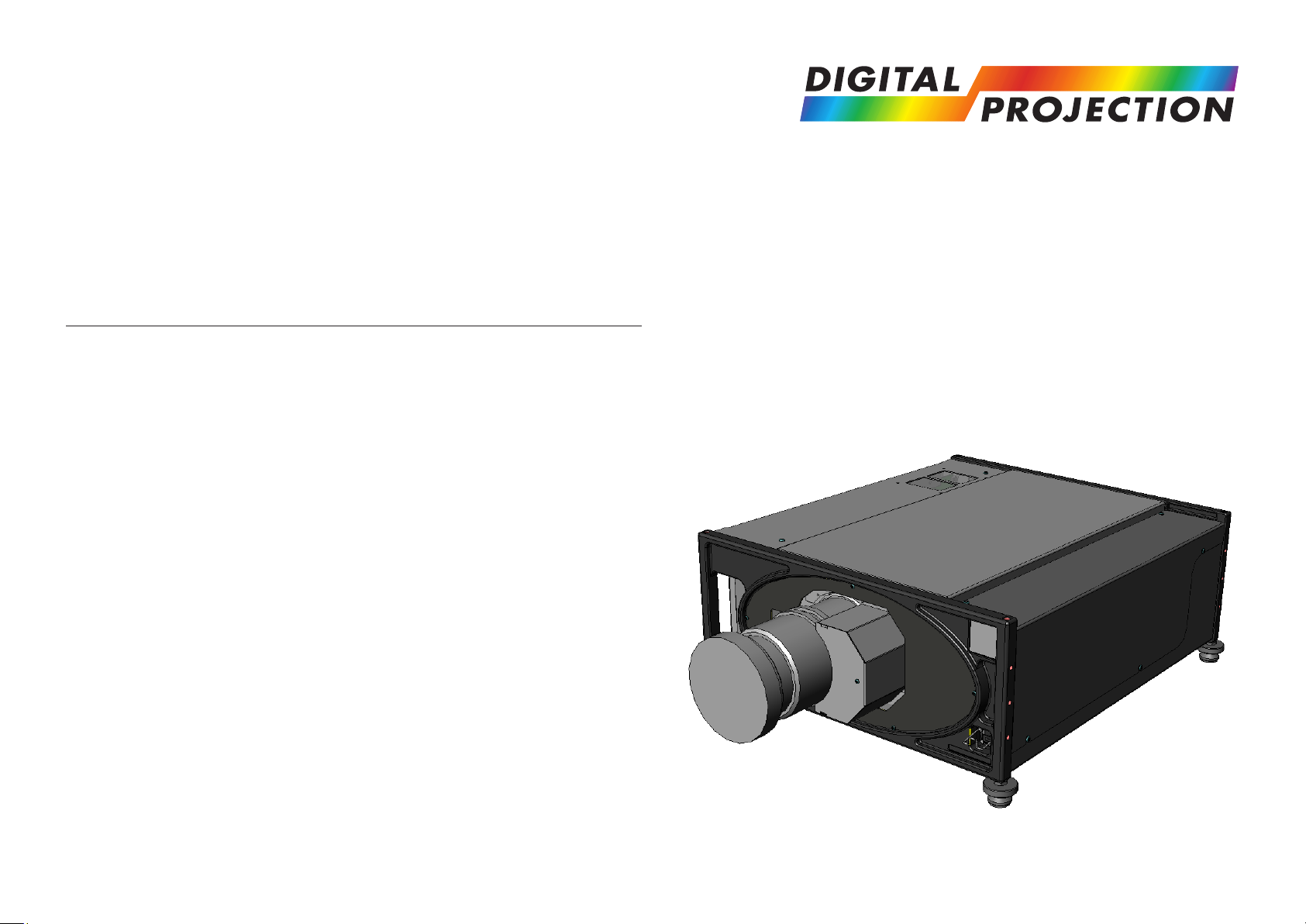
Titan Pro series III
High Brightness Digital Video Projector
USER GUIDES
INSTALLATION AND QUICK-START GUIDE
CONNECTION GUIDE
OPERATING GUIDE
Rev A May 2012
112-884A
Page 2
Digital Projection Titan Pro series III ABOUT THESE GUIDES
About these Guides
Please read this guide carefully before using the projector, and keep it handy for future reference.
A serial number is located on the back of the projector. Record it here:
Symbols used in these guides
Warnings
ELECTRICAL WARNING: this symbol indicates that there is a danger of electrical shock unless the instructions are closely
followed.
WARNING: this symbol indicates that there is a danger of physical injury to yourself and/or damage to the equipment unless
the instructions are closely followed.
Notes
NOTE: this symbol indicates that there is some important information that you should read.
Product revision
Because we at Digital Projection continually strive to improve our products, we may change specifications and designs, and add new features
without prior notice. Projectors built prior to this revision of the Operating Guide may therefore not include all the features described.
Rev A May 2012
Page 3

INSTALLATION AND QUICK-START GUIDE
Titan Pro series III
High Brightness Digital Video Projector
Rev A May 2012
Page 4

Digital Projection Titan Pro series III CONTENTS Installation and Quick-Start Guide
CONTENTS
What’s in the Box? ...............................................................................Inst_1
Getting to Know the Projector....................................................Inst_2
Front and rear views .............................................................................Inst_2
Control panel .........................................................................................Inst_3
Remote control ......................................................................................Inst_3
Connection panel indicators ................................................................Inst_4
Positioning the Screen and Projector ....................................Inst_5
Tilting the Projector ..............................................................................Inst_5
Chassis adjustment ..............................................................................Inst_5
Fitting and adjusting the optional Rigging Frame .............................Inst_6
Fitting ............................................................................................Inst_6
Stacking ........................................................................................Inst_6
Pitch, Roll and Yaw .......................................................................Inst_6
Redirecting the Air Outlet Duct ............................................................Inst_7
Fitting the Lens .....................................................................................Inst_8
Lens Calibration ....................................................................................Inst_8
Operating the Projector ...................................................................Inst_9
Switching the Projector On ..................................................................Inst_9
Selecting an Input Signal or Test Pattern ...........................................Inst_9
Input signal ....................................................................................Inst_9
Test pattern ...................................................................................Inst_9
Adjusting the Lens ..............................................................................Inst_10
Zoom ...........................................................................................Inst_10
Focus ..........................................................................................Inst_10
Shift .............................................................................................Inst_10
Adjusting the Image ............................................................................Inst_10
Orientation...................................................................................Inst_10
Control settings ...........................................................................Inst_10
Keystone .....................................................................................Inst_10
Picture .........................................................................................Inst_10
Switching the Projector Off ................................................................ Inst_11
Rev A May 2012
Page 5
Digital Projection Titan Pro series III WHAT'S IN THE BOX? Installation and Quick-Start Guide
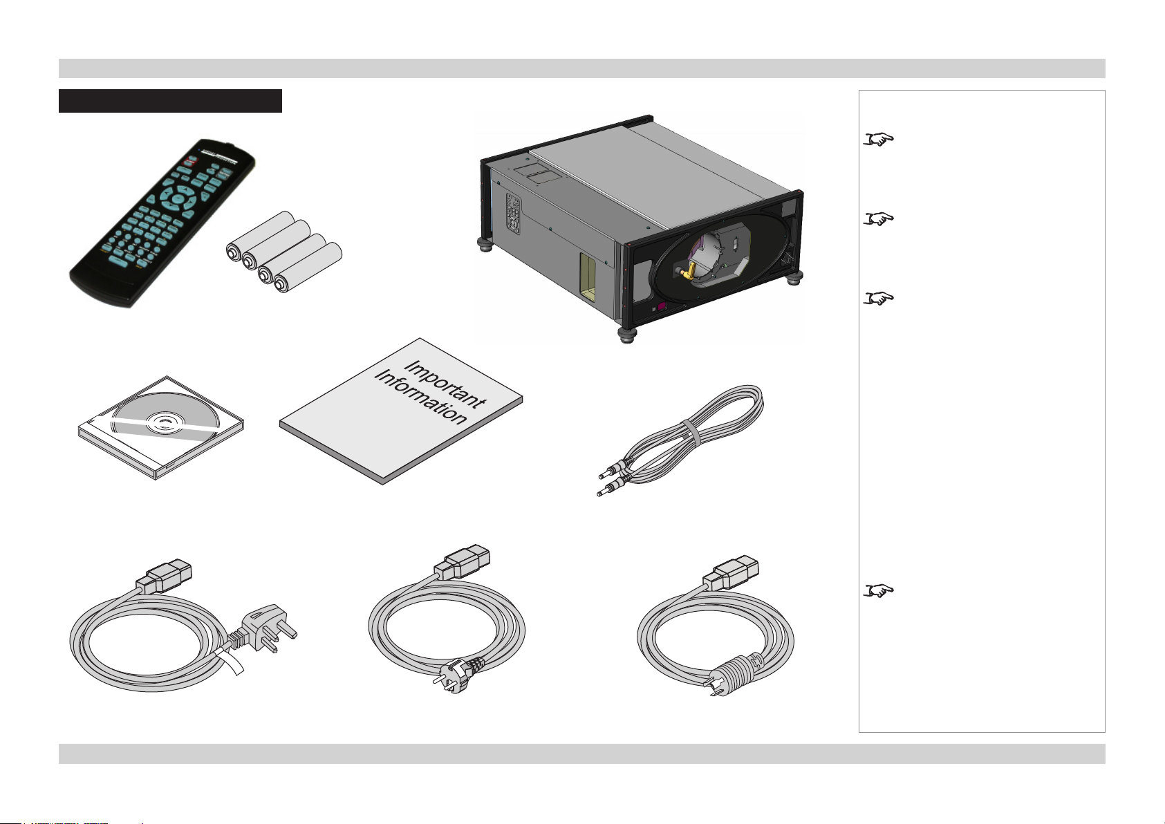
What’s in the Box?
4x AAA batteries
Remote control
(105-023)
User Guides on CD
(112-889)
Important Information
(112-888)
Notes
Make sure your box contains
everything listed. If any pieces are
missing, contact your dealer.
You should save the original box
and packing materials, in case you
ever need to ship your Projector.
The projector is shipped without a
lens.
Projector
Remote cable
(102-162)
Power cable, United Kingdom
(112-000)
Power cable, Europe
(112-001)
Only one power cable - dependent
on the destination territory - will be
supplied with the projector.
Power cable, North America
(112-002)
Page Inst_1Rev A May 2012
Page 6
Digital Projection Titan Pro series III GETTING TO KNOW THE PROJECTOR Installation and Quick-Start Guide
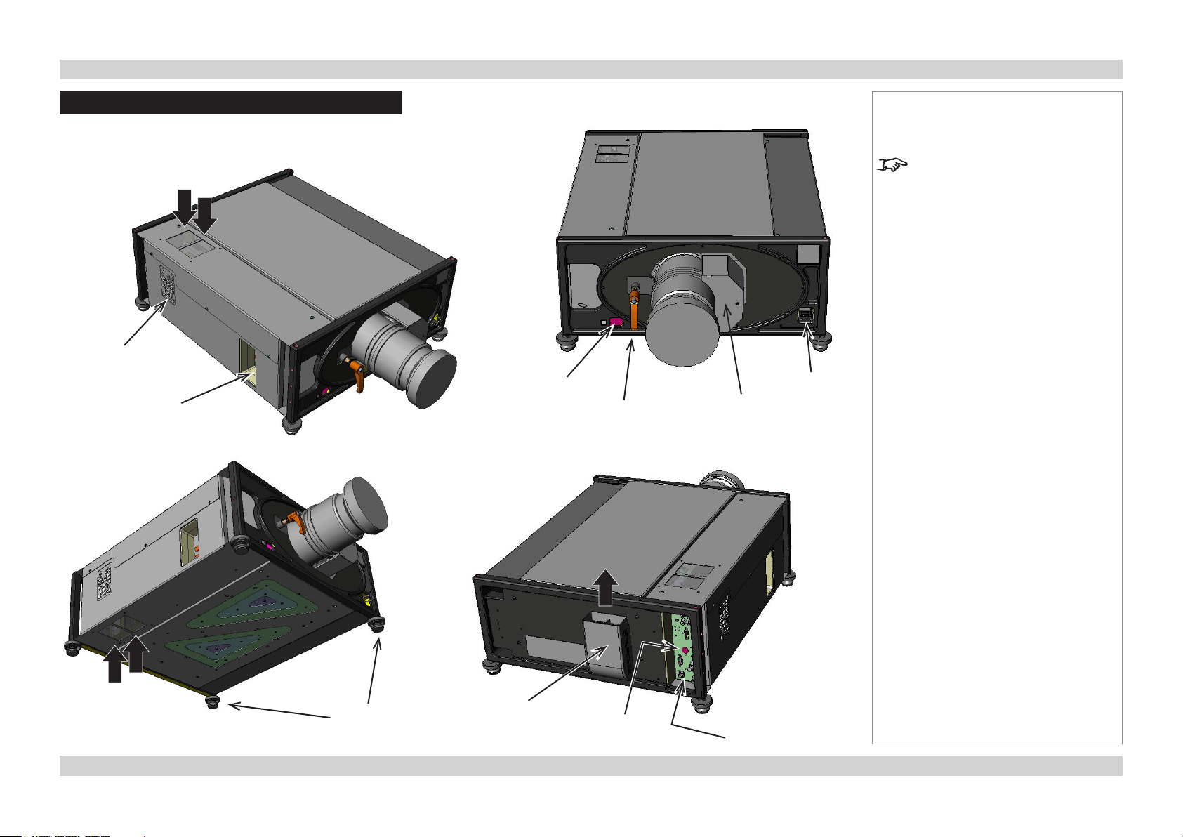
Getting to Know the Projector
Front and rear views
Top
air inlets
Control
panel
Side
Connection
panel
Front
infra-red
window
Lens
Lens release
lever
Notes
For full details of how to use the
controls and the menu system, see
the Operating Guide.
Mains
input
Lens
motor
Bottom
air inlets
Adjustable
feet
Air outlet
duct
Rear
infra-red window
Rear
Connection panel
Page Inst_2Rev A May 2012
Page 7
Digital Projection Titan Pro series III GETTING TO KNOW THE PROJECTOR Installation and Quick-Start Guide
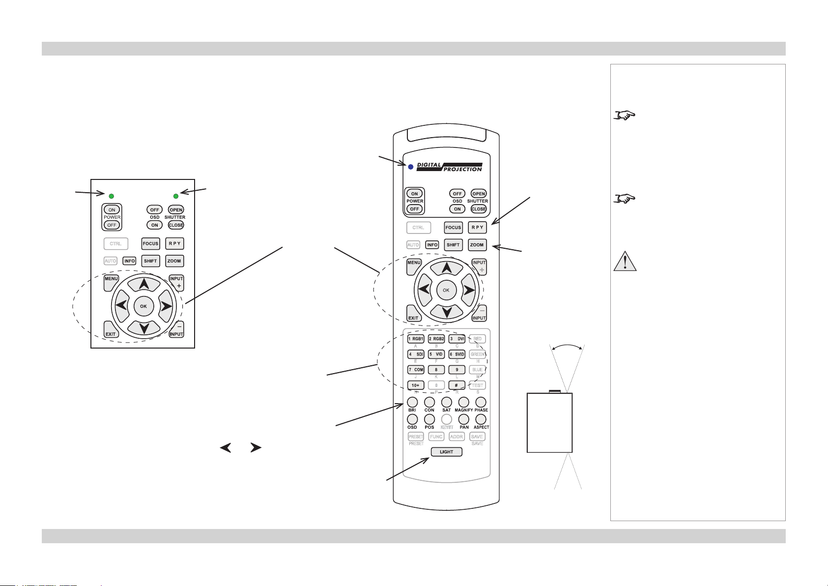
Control panel
The indicators on the control panel are as follows:
Power off = NO POWER
green = normal RUNNING mode amber = STANDBY mode
Shutter amber = CLOSED green = OPEN
Power
Shutter
Menu
controls
Transmit
indicator
Remote control
(RPY) Lens
calibration
See Fitting the
Lens.
Lens controls
Notes
The projector uses the standard
Digital Projection infra-red remote
control.
Only the controls shown highlighted
are used on this projector.
For full details of how to use the
controls and the menu system, see
the Operating Guide.
Each time a lens is fitted to
the projector, the calibration
procedure must be carried out.
(see the Fitting the Lens)
Input selection
1–10 selects Inputs 1 to 10
# selects Dual Pipe (inputs 9+10)
Image adjustment
Brightness, Contrast and Saturation
use and to adjust sliders
Remote
control
backlight
On/Off
40°
40°
Infra-red
reception
Page Inst_3Rev A May 2012
Page 8
Digital Projection Titan Pro series III GETTING TO KNOW THE PROJECTOR Installation and Quick-Start Guide
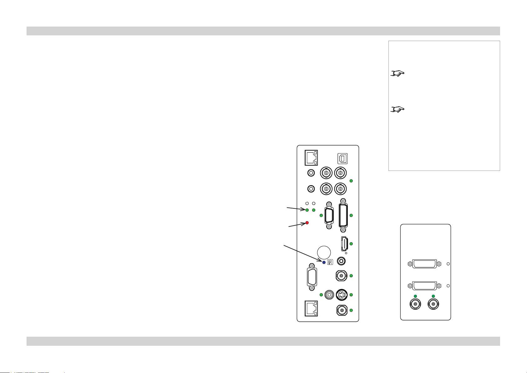
Connection panel indicators
The indicators on the rear connection panel are as follows:
All on = Power-On Self Test
Lamps 1,2 off = OFF
green = ON (100%) amber = 85-99% (on some models)
flashing green = WARM-UP flashing amber = COOL-DOWN
red (projector in standby) = Lamp Comms Error (call service)
red (projector on) = Ballast Comms Error (call service)
flashing red (projector in standby) = Lamp Error on previous operation
flashing red (projector on) = Lamp / Interlock Error
Error flashing = Fan / System Error steady = Voltage Error
IR blue flash = Remote control command received
Inputs The indicators next to the input connectors on both panels are as follows:
off = not selected
green = input selected, signal detected, and in range
flashing green = input selected, but signal not detected or out of range
Notes
For full details of how to use the
controls and the menu system, see
the Operating Guide.
For more information about
the connection panels, see the
Connection Guide.
Lamps
1 2
Error
IR
Rear Connection Panel Side Connection Panel
Page Inst_4Rev A May 2012
Page 9
Digital Projection Titan Pro series III POSITIONING THE SCREEN AND PROJECTOR Installation and Quick-Start Guide
Positioning the Screen and Projector
Install the screen, ensuring that it is in the best position for viewing by your audience.
•
Position the projector, ensuring that it is at a suitable distance from the screen for the image to fill the screen.
•
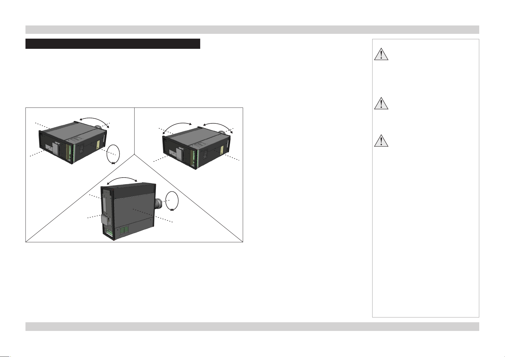
Tilting the Projector
Do not tilt the projector more than is shown in the tilt diagrams, when in use, as this may cause serious lamp failure, damage the
lamp module and cause extra cost on replacement.
SX+ 3D-L
1080p 3D-L
WUXGA 3D-L
±10°
180°
±10°
±10°
180°
±10°
SX+ 660
1080p 660
WUXGA 660
Notes
Always allow the lamp to cool for
5 minutes before:
- disconnecting the power
- moving the projector
Ensure that there is at least
30cm (12in) of space between the
ventilation outlets and any wall,
and 10cm (4in) on all other sides.
Do not place the projector with its
front panel down on a surface, as
this may damage the lens or the
lens release lever.
SX+ 3D-P
1080p 3D-P
WUXGA 3D-P
Chassis adjustment
If the projector is to be operated from a flat surface such as a projector table, then
•
adjustment of projector level should be made by turning the four feet under the chassis.
Set the adjustable feet so that the projector is level, and perpendicular to the sceen.
Page Inst_5Rev A May 2012
Page 10
Digital Projection Titan Pro series III POSITIONING THE SCREEN AND PROJECTOR Installation and Quick-Start Guide
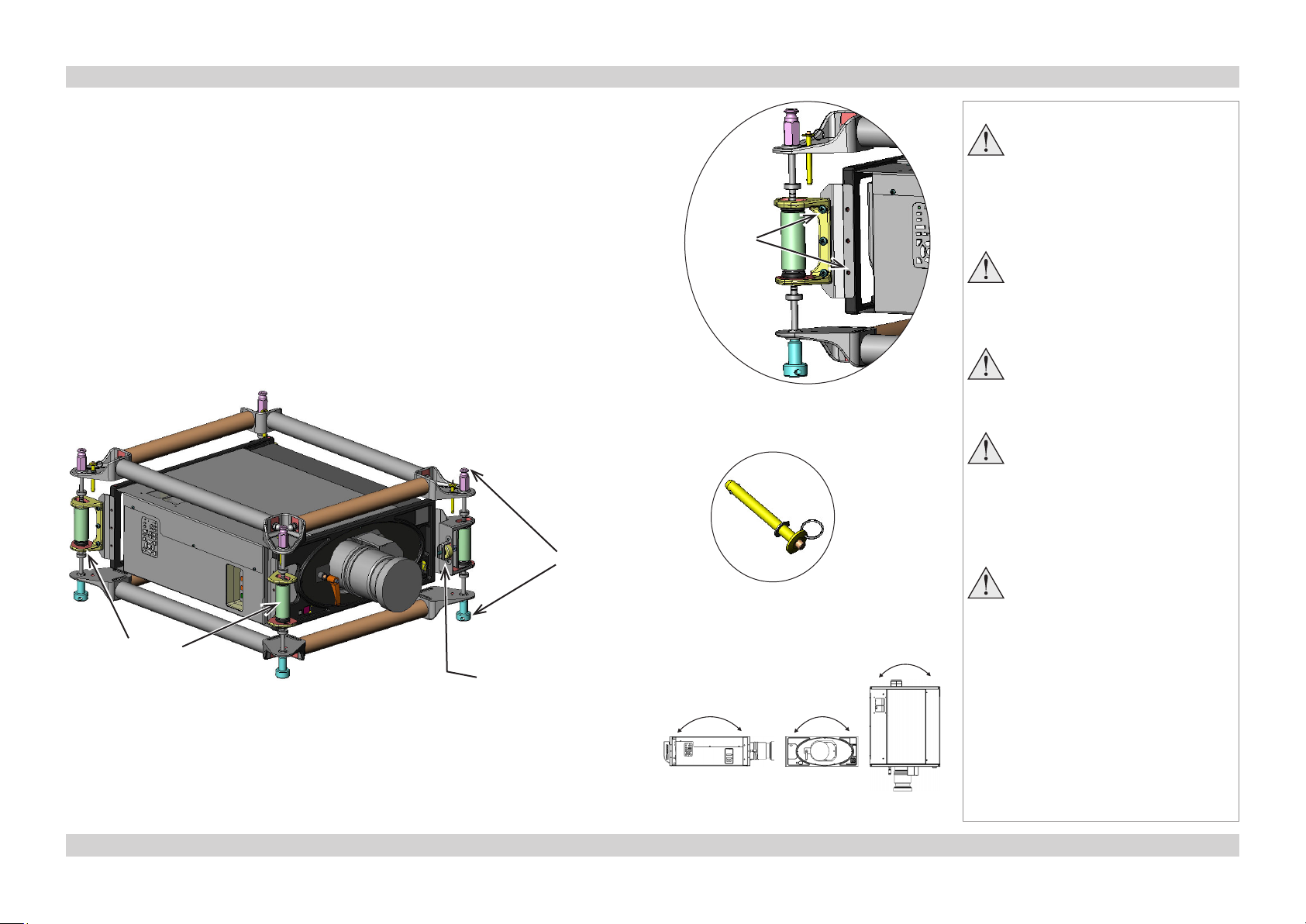
Fitting and adjusting the optional Rigging Frame
Fitting
Remove the four adjustable feet.
•
Secure the rigging frame to the projector, as shown, making sure that the male frame
•
couplings are at the top. Secure each adaptor plate to the projector (three screws), and
secure each of the adjuster brackets to an adaptor plate (three screws).
Stacking
The projectors can be stacked on top of each other, or suspended below each other.
Carefully lower each projector down onto the top of the others, making sure that all four
•
frame couplings engage fully.
Fit a locking pin into each coupling. A ball in the end of the pin prevents the pin from
•
falling out – to insert or remove a locking pin, press the button on the end of the pin to
release the ball.
couplings
Frame
Fixing
screws
(2 x 3)
Locking
pin
Notes
Always allow the lamp to cool for
5 minutes before:
- disconnecting the power
- moving the projector
Do not place the projector with its
front panel down on a surface, as
this may damage the lens or the
lens release lever.
Do not stack more than 3
projectors.
Do not place heavy objects on top
of the projector chassis. Only the
chassis corners and the rigging
frame are capable of withstanding
the weight of another projector.
Backup safety chains or wires
should always be used with
ceiling mount installations.
Vertical
adjusters
Horizontal
adjuster
Pitch, Roll and Yaw
To adjust the pitch, turn either the front pair or the rear pair of vertical adjusters, taking
•
care to turn both adjusters by the same amount.
To adjust the roll, turn either the left pair or the right pair of vertical adjusters, taking care
•
to turn both adjusters by the same amount.
To adjust the yaw, turn the single horizontal adjuster at the front.
•
Pitch Roll Yaw
Page Inst_6Rev A May 2012
Page 11
Digital Projection Titan Pro series III POSITIONING THE SCREEN AND PROJECTOR Installation and Quick-Start Guide
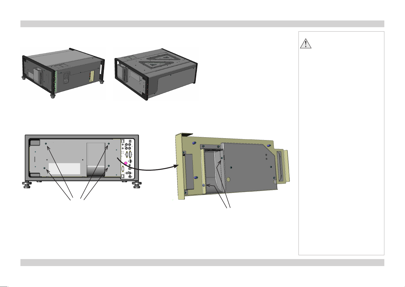
Redirecting the Air Outlet Duct
The duct can be set to blow upwards whether the projector is in desktop or ceiling mode, as shown below.
Unscrew the four screws securing the rear cover, then remove the cover.
•
Working from the back of the cover panel, unscrew the two screws securing the duct
•
Turn the duct through 180°, refit the two screws, then refit the cover.
•
Notes
Always allow the lamp to cool for
5 minutes before:
- disconnecting the power
- moving the projector
Rear cover
screws x4
Duct screws x2
Page Inst_7Rev A May 2012
Page 12
Digital Projection Titan Pro series III FITTING THE LENS Installation and Quick-Start Guide
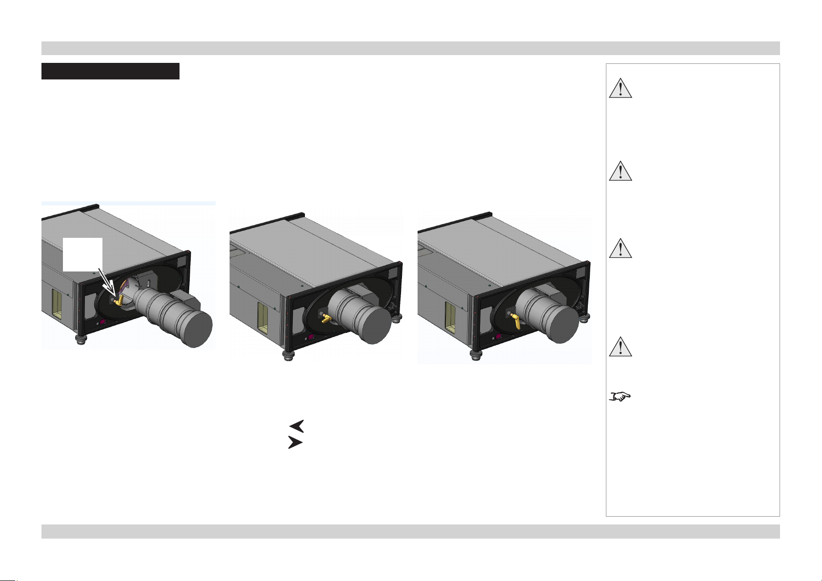
Fitting the Lens
Turn the lens release lever clockwise so
•
that it is pointing upwards, to open the
lock fully.
Remove the rear lens cap from the lens.
•
Insert the lens into the lens aperture,
•
making sure that the plug on the zoom
drive mechanism lines up with the
socket on the front of the projector, then
push the lens in firmly as far as it will go.
Lens
release
lever
Turn the lens release lever anti-
•
clockwise to the mid-position.
The lens can now be pushed in further.
•
Push the lens in firmly as far as it will
go.
Turn the lens release lever fully
•
anti-clockwise so that it is pointing
downwards, to close the lock fully.
Notes
Always allow the lamp to cool for
5 minutes before:
- disconnecting the power
- moving the projector
The lens release lever should
always be set to the locked
position to prevent the lens from
falling out.
Do not place the projector with its
front panel down on a surface, as
this may damage the lens or the
lens release lever.
Each time a lens is fitted to
the projector, the calibration
procedure must be carried out.
Lens Calibration
Each time a lens is fitted, the lens mechanism needs to be calibrated, as follows:
Press RPY on the remote control or the control panel, then , to calibrate the Zoom mechanism.
•
Press RPY on the remote control or the control panel, then , to calibrate the Focus mechanism.
•
The drive mechanism will travel to both extremes, then stop.
After calibrating the lens, you will
need to re-adjust the Zoom and
Focus.
Page Inst_8Rev A May 2012
Page 13
Digital Projection Titan Pro series III OPERATING THE PROJECTOR Installation and Quick-Start Guide
Operating the Projector
Switching the Projector On
Connect the power cable between the mains supply and the projector. Switch on at the switch next to the power connector.
•
Wait until the self-test has completed and the standby indicator on the projector control panel shows amber. The lamp will be off and the
•
projector will be in STANDBY mode.
Press on the remote control or the control panel and hold for 3 seconds, to switch the projector ON. The power indicator on the
•
control panel will show green, the lamp will light and the shutter will open.
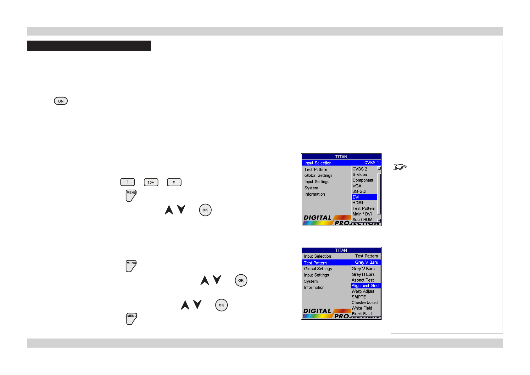
Selecting an Input Signal or Test Pattern
Input signal
Connect an image source to the projector. The signal should be automatically detected by the
•
projector, and should be displayed within a two or three seconds.
If more than one signal is connected, then select the image you want to display:
Press one of the Input buttons, to or (dual pipe) on the remote control, or
•
Open the Main Menu, by pressing .
•
Select from the Input Selection menu, using the and buttons.
•
Notes
For full details of how to use the
controls and the menu system, see
the Operating Guide.
Test pattern
If you have no image source connected to the projector, then you can display a test pattern instead:
Open the Main Menu, by pressing .
•
Select Test Pattern from the Input Selection menu, using the and buttons.
•
Select a pattern from the Test Pattern menu, using the and buttons.
•
Close the Main Menu, by pressing again.
•
Page Inst_9Rev A May 2012
Page 14
Digital Projection Titan Pro series III OPERATING THE PROJECTOR Installation and Quick-Start Guide
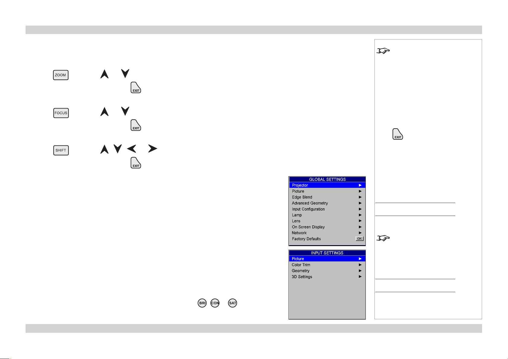
Adjusting the Lens
The lens can be adjusted using the Lens Menu, which is available from the Global Settings Menu, or:
•
Zoom
Press followed by and to adjust the size of the image on the screen.
•
When the adjustment is finished, press .
•
Focus
Press followed by and to adjust the focus.
•
When the adjustment is finished, press .
•
Shift
Press followed by , , and to adjust the position of the image on the screen.
•
When the adjustment is finished, press .
•
Adjusting the Image
Orientation
This can be set from the Projector Menu, which is available from the Global Settings Menu.
•
Notes
When any of the three Lens
adjustment keys is pressed, the blue
Transmit indicator on the remote
control will light for 10 seconds:
- after 10 seconds, if no adjustment
has been made, the indicator will
go out and the Lens adjustment key
must be pressed again to resume
adjustment.
- to end the adjustment before 10
seconds has elapsed, press the
key.
- all other adjustments will be locked
out until the Lens adjustment is
ended.
Main Menu
Global Settings
Control settings
Settings for the On-Screen Display and Network can be set from the Global Settings Menu.
•
Keystone
This can be set from the Advanced Geometry Menu, which is available from the Global Settings
•
Menu.
Picture
Settings such as Brightness and Contrast can be set from the Picture Menu, which is available
•
from the Input Settings Menu.
You can also set Brightness, Contrast or Saturation by pressing , or on the remote
•
control.
For full details of how to use the
controls and the menu system, see
the Operating Guide.
Main Menu
Input Settings
Page Inst_10Rev A May 2012
Page 15
Digital Projection Titan Pro series III OPERATING THE PROJECTOR Installation and Quick-Start Guide
Switching the Projector Off
Press on the remote control or the control panel, and hold for 3 seconds, to switch the projector OFF. The power indicator on the
•
control panel will show amber, the lamp will be off and the projector will be in STANDBY mode.
Switch off at the switch next to the power connector. Disconnect the power cable from the projector.
•
Notes
Always allow the lamp to cool for
5 minutes before:
- disconnecting the power
- moving the projector
Page Inst_11Rev A May 2012
Page 16
Titan Pro series III
High Brightness Digital Video Projector
CONNECTION GUIDE
Rev A May 2012
Page 17

Digital Projection Titan Pro series III CONTENTS Connection Guide
CONTENTS
Signal Inputs and Outputs ..........................................................Conn_1
Rear Connection Panel ...................................................................... Conn_1
VGA (input 1) ....................................................................................... Conn_1
HDMI (input 2) ..................................................................................... Conn_1
DVI (input 3) ......................................................................................... Conn_1
SPDIF.........................................................................................Conn_1
3G-SDI (input 4) .................................................................................. Conn_1
CVBS1 (Composite video BNC) (input 5) ............................................ Conn_1
S-Video (input 6) ................................................................................. Conn_1
Component (input 7) ........................................................................... Conn_1
CVBS2 (Composite video RCA phono) (input 8) ................................. Conn_1
Side Connection Panel ......................................................................Conn_2
DVI (input 9) ......................................................................................... Conn_2
DVI/HDMI (input 10) ............................................................................ Conn_2
Differences between the two Connection Panels ...........................Conn_2
3D Connections .................................................................................. Conn_3
3D sources up to 60Hz requiring frame doubling and left/right
interleaving .................................................................................Conn_3
3D sources above 60Hz not requiring frame doubling ............... Conn_3
Dual Pipe 3D .............................................................................. Conn_3
3D Sync in ..................................................................................Conn_3
3D Sync out................................................................................Conn_3
Control Connections .......................................................................Conn_5
Update Port ................................................................................ Conn_5
Service Port................................................................................Conn_5
Wired Remote Control................................................................Conn_5
RS232 ........................................................................................Conn_5
LAN ............................................................................................Conn_5
Wiring Details....................................................................................... Conn_6
Signal inputs and outputs .................................................................Conn_6
Component input ........................................................................Conn_6
VGA input ...................................................................................Conn_6
DVI-I input ..................................................................................Conn_7
HDMI input .................................................................................Conn_8
SPDIF output..............................................................................Conn_8
CVBS inputs ...............................................................................Conn_8
S-Video input ..............................................................................Conn_9
3G-SDI .......................................................................................Conn_9
Control connections ........................................................................Conn_10
Wired Remote control connection ............................................ Conn_10
Serial control input ...................................................................Conn_10
LAN connection ........................................................................ Conn_11
Supported Signal Input Modes................................................. Conn_4
Rev A May 2012
Page 18

Digital Projection Titan Pro series III SIGNAL INPUTS AND OUTPUTS Connection Guide
Signal Inputs and Outputs
Rear Connection Panel
VGA (input 1)
Use Auto Setup in the Input Settings/Picture/VGA Setup menu. For more settings,
•
see the Operating Guide.
HDMI (input 2)
For settings, see the Operating Guide.
•
DVI (input 3)
Analog or Digital DVI-I
Set DVI-I Port in the Global Settings/Input Conguration menu to choose between
•
Analog and Digital. For more settings, see the Operating Guide.
SPDIF
Compatible audio sample packets on the HDMI input stream are decoded by the
•
projector and output on the SPDIF connector. This is a digital output.
3G-SDI (input 4)
If two video streams are being transmitted, set 3G Level B Stream in the Input
•
Conguration menu to choose between the two streams.
CVBS1 (Composite video BNC) (input 5)
S-Video (input 6)
Component (input 7)
RGsB or RGBS
Set Component Colour Space in the Global Settings/Input Conguration menu to
•
RGB.
Set Component Sync Type to Auto, except when the projector has problems selecting
•
between 3 Wire (RGsB) and 4 Wire (RGBS).
YPbPr
Set Component Colour Space in the Global Settings/Input Conguration menu to
•
YPbPr.
CVBS2 (Composite video RCA phono) (input 8)
Notes
For a complete listing of pin
configurations for all signal and
control connectors, see Wiring
Details later in this Guide.
See the next page for important
information about the differences
between the two connection panels.
Component (Input 7)
DVI (Input 3)
VGA (Input 1)
HDMI (Input 2)
SPDIF
CVBS1 (Input 5)
CVBS2 (Input 8)
S-Video (Input 6)
3G-SDI (Input 4)
Rear Connection Panel
Page Conn_1Rev A May 2012
Page 19

Digital Projection Titan Pro series III SIGNAL INPUTS AND OUTPUTS Connection Guide
Side Connection Panel
MAIN/DVI (input 9)
Single or Dual Link DVI-D input
•
SUB/HDMI (input 10)
Single HDMI 1.4 input (using an adaptor), or
•
Single or Dual Link DVI-D input
•
For information about 3D video, see the next page.
Differences between the two Connection Panels
Inputs 9 and 10 have been designed to give a very high bandwidth digital video path, free of
the limitations inherent to standard image processing techniques.
As such, the image is pixel-mapped directly to the DMDs, so not all of the Image Controls
available to Inputs 1-8 apply to Inputs 9 and 10.
Notes
For a complete listing of pin
configurations for all signal and
control connectors, see Wiring
Details later in this Guide.
MAIN/DVI
(Input 9)
SUB/HDMI
(Input 10)
Side Connection Panel
Page Conn_2Rev A May 2012
Page 20

Digital Projection Titan Pro series III SIGNAL INPUTS AND OUTPUTS Connection Guide
3D Connections
3D sources up to 60Hz requiring frame doubling and left/right interleaving
Connect to any of the Inputs on the Rear Connection Panel.
•
Set 3D Type in the Input Settings/3D Settings menu to Auto, except when the
•
projector has problems selecting between Sequential, Frame Packing, Top-and-
Bottom and Side-by-Side (Half).
3D sources above 60Hz not requiring frame doubling
Connect to either of the Inputs on the Side Connection Panel.
•
Set 3D Type in the Input Settings/3D Settings menu to Auto, except when the
•
projector has problems selecting between Sequential, Frame Packing, Top-and-
Bottom and Side-by-Side (Half).
Dual Pipe 3D
Connect to both of the Inputs on the Side Connection Panel.
•
Input 9 (MAIN/DVI) is the left image, and Input 10 (SUB/HDMI) is the right image.
•
3D Sync in
Sync input signal.
•
3D Sync out
Sync output signal. This may be affected by the Sync Offset and Output Sync Polarity
•
settings in the Input Settings/3D Settings/Glasses Settings menu.
3D Sync in
3D Sync out
Notes
For a complete listing of pin
configurations for all signal and
control connectors, see Wiring
Details later in this Guide.
MAIN/DVI
(Input 9)
together:
Dual Pipe 3D
SUB/HDMI
Input 10
3D Server
Side Connection Panel
Projector
Video
Sync Sync in
Sync out
3D glasses or
Z screen
Page Conn_3Rev A May 2012
Page 21

Digital Projection Titan Pro series III SUPPORTED SIGNAL INPUT MODES Connection Guide
Supported Signal Input Modes
Signal Resolution Refresh
Rate
( Hz )
SDTV 480i 720 x 480 60 525 15.73
576i 720 x 576 50 625 15.63
HDTV 480p 720 x 480 60 525 31.51
576p 720 x 576 50 625 31.25
720p50 1280 x 720 50 750 37.51
720p60 1280 x 720 60 750 45.00
1080psf24 1920 x 1080 48 1125 27.00
1080p24 1920 x 1080 24 1125 27.00
1080i50 1920 x 1080 50 1125 28.13
1080p25 1920 x 1080 25 1125 28.13
1080i60 1920 x 1080 60 1125 33.75
1080p30 1920 x 1080 30 1125 33.75
1080p50 1920 x 1080 50 1125 56.24
1080p60 1920 x 1080 60 1125 67.48
COMPUTER 480p 640 x 480 60 525 31.47
VGA72 640 x 480 72 520 37.86
VGA75 640 x 480 75 500 37.50
SVGA56 800 x 600 56 625 35.16
SVGA60 800 x 600 60 628 37.88
SVGA72 800 x 600 72 666 48.08
XGA60 1024 x 768 60 806 48.36
XGA70 1024 x 768 70 806 56.48
XGA85 1024 x 768 85 808 68.68
WXGA60 1280 x 768 60 798 47.78
WXGA+60 1440 x 900 60 934 55.94
SXGA60 1280 x 1024 60 1066 63.98
SXGA+60 1400 x 1050 60 1089 65.32
UXGA60 1600 x 1200 60 1245 75.00
VESA1080p 1920 x 1080 60 1120 67.50
WUXGA60 1920 x 1200 60 1235 74.038
Total
number
of lines
Horizontal
Frequency
(kHz)
VGA
DVI / HDMI
COMPOSITE
S-VIDEO
COMPONENT
ü ü ü ü
ü ü ü ü
ü ü
ü ü
ü ü ü
ü ü ü
ü ü ü
ü ü ü
ü ü
ü ü ü
ü ü ü
ü ü ü
ü ü
ü ü
ü ü
ü ü
ü ü
ü ü
ü ü
ü ü
ü ü
ü ü
ü ü
ü ü
ü ü
ü ü
ü ü
ü ü
ü ü
ü ü
Notes
SDI
Page Conn_4Rev A May 2012
Page 22

Digital Projection Titan Pro series III CONTROL CONNECTIONS Connection Guide
Control Connections
Update Port
The Update Port is used to download via LAN, firmware updates issued from time to time
•
by Digital Projection.
Service Port
The Service Port is used to download via USB, firmware updates issued from time to
•
time by Digital Projection.
Wired Remote Control
If infrared signals from the remote control cannot reach the projector due to excessive
•
distance or obstructions such as walls or cabinet doors, you can connect an external
IR repeater to the Remote control input, and position its IR sensor within range of the
operator.
To synchronise the control of multiple projectors, connect the Wired Remote Output of
•
one projector to the Wired Remote Input of another.
Note that plugging in the remote control cable will disable the infra-red.
RS232
All of the projector’s features can be controlled via a serial connection, using the text
•
strings described in the External Control Protocol..
Use a null-modem cable to connect directly to a computer, or a straight cable to connect
•
to a modem.
Update
Port
Wired Remote
Input
Wired Remote
Output
Notes
For a complete listing of pin
configurations for all signal and
control connectors, see Wiring
Details later in this Guide.
Only one remote connection (RS232
or LAN) should be used at any one
time.
Service
Port
LAN
All of the projector’s features can be controlled via a LAN connection, using the text
•
strings described in the External Control Protocol..
Alternatively, for details of how to use the Web Configuration Utility to control the
•
projector, see the Operating Guide.
Use a crossed LAN cable to connect directly to a computer, or an uncrossed cable to
•
connect to a network hub.
RS232
LAN
Rear Connection Panel
Page Conn_5Rev A May 2012
Page 23

Digital Projection Titan Pro series III WIRING DETAILS Connection Guide
Wiring Details
Signal inputs and outputs
Component input
4 x 75 ohm BNC
RGsB RGBS YPrPb
Pb/B B B Pb/Cb
Y/G G + Sync G Y
Pr/R R R Pr/Cr
SYNC Sync
VGA input
15 way D-type connector
1 R
2 G
3 B
4 unused
5 Digital Ground (H Sync)
6 R Ground
7 B Ground
8 G Ground
9 +5v
10 Digital Ground (V Sync/DDC)
11 unused
12 SDA
13 H Sync
14 V Sync
15 SCL
Notes
For full details of all input settings,
see the Global Settings/Input
Configuration menu, and the
Input Settings Picture menu in the
Operating Guide.
pin view of female connector
Page Conn_6Rev A May 2012
Page 24

Digital Projection Titan Pro series III WIRING DETAILS Connection Guide
DVI-I input
24 way D-type connector
1 TMDS Data 2-
2 TMDS Data 2+
3 TMDS Data 2 Shield
4 unused
5 unused
6 DDC Clock
7 DDC Data
8 unused
9 TMDS Data 1-
10 TMDS Data 1+
11 TMDS Data 1 Shield
12 unused
13 unused
14 +5 V Power
15 Ground
16 Hot Plug Detect*
17 TMDS Data 0-
18 TMDS Data 0+
19 TMDS Data 0 Shield
20 unused
21 unused
22 TMDS Clock Shield
23 TMDS Clock+
24 TMDS Clock-
pin view of female connector
Notes
For full details of all input settings,
see the Global Settings/Input
Configuration menu, and the
Input Settings Picture menu in the
Operating Guide.
* Hot plug detect (HPD) is fully DVI compliant. DVI sources detect the presence of a display device by providing +5V on pin 14 and looking
for +5V on pin 16. Whenever the projector is operational, and 5V is present on pin 14, pin 16 will be held at +5V.
EDID is available even when the projector is switched off.
Operational means that the projector is powered up. Non operational states are powered down and some self test and reprogramming
modes.
High Definition Content Protection (HDCP) is supported on this input.
Page Conn_7Rev A May 2012
Page 25

Digital Projection Titan Pro series III WIRING DETAILS Connection Guide
HDMI input
19 way type A connector
1 TMDS Data 2+
2 TMDS Data 2 Shield
3 TMDS Data 2-
4 TMDS Data 1+
5 TMDS Data 1 Shield
6 TMDS Data 1-
7 TMDS Data 0+
8 TMDS Data 0 Shield
9 TMDS Data 0-
10 TMDS Clock+
11 TMDS Clock Shield
12 TMDS Clock-
13 CEC
14 not connected
15 SCL (DDC Clock)
16 SCA (DDC Data)
17 DDC/CEC Ground
18 +5 V Power
19 Hot Plug Detect
pin view of panel connector
Notes
For full details of all input settings,
see the Global Settings/Input
Configuration menu, and the
Input Settings Picture menu in the
Operating Guide.
SPDIF output
RCA Phono
Digital audio output from the HDMI input stream.
CVBS inputs
CVBS1: 75 ohm BNC
CVBS2: RCA Phono
Page Conn_8Rev A May 2012
Page 26

Digital Projection Titan Pro series III WIRING DETAILS Connection Guide
S-Video input
4 pin mini-DIN
1 Y Ground
2 C Ground
3 Luminance (Y)
4 Chrominance (C)
3G-SDI
75 ohm BNC
SMPTE 292 / HD-SDI signals are very high speed digital signals which require better quality
coaxial cable than conventional analogue video. The data rate is 1.5 Gigabits per second.
In choosing cable length and connectors for any installation the frequency response loss
in decibels should be proportional to √f, from 1MHz, to 1.5GHz. The following or similar
cable specification should be used to ensure fault free communication between source and
projector:
Belden 8281 cable or equivalent
pin view of female connector
Notes
For full details of all input settings,
see the Global Settings/Input
Configuration menu, and the
Input Settings Picture menu in the
Operating Guide.
Page Conn_9Rev A May 2012
Page 27

Digital Projection Titan Pro series III WIRING DETAILS Connection Guide
Control connections
Wired Remote control connection
3.5mm mini jack
Tip Power
Ring Signal
Sleeve Ground
Serial control input
1 unused
2 Received Data (RX)
3 Transmitted Data (TX)
4 unused
5 Signal Ground
6 unused
7 unused
8 unused
9 unused
Null-modem cable
(used to connect the projector to a computer)
RX 2 --- 3 TX
TX 3 --- 2 RX
GND 5 --- 5 GND
Tip
Sleeve
Ring
pin view of female connector
Notes
Note that plugging in the remote
control cable will disable the infrared.
Only one remote connection (RS232
or LAN) should be used at any one
time.
The projector is a DTE, so use:
a straight cable to connect to a
modem, or
a null-modem cable as shown here
to connect to another DTE such as a
computer.
Serial port settings
Baud rate 9,600 bps
Data length 8 bits
Stop bits one
Parity none
Flow control none
Page Conn_10Rev A May 2012
Page 28

Digital Projection Titan Pro series III WIRING DETAILS Connection Guide
LAN connection
TCP Port number
10001
10BaseT Unshielded Twisted Pair cable
The standard wire colours as as follows:
1 White / Orange stripe
2 Orange
3 White / Green stripe
4 Blue
5 White / Blue stripe
6 Green
7 White / Brown stripe
8 Brown
Crossed cable
(used to connect directly to a computer with no hub or network.)
(Note that only the green and orange pairs are crossed)
1 White / Orange stripe White / Green stripe 1
2 Orange Green 2
3 White / Green stripe White / Orange stripe 3
4 Blue Blue 4
5 White / Blue stripe White / Blue stripe 5
6 Green Orange 6
7 White / Brown stripe White / Brown stripe 7
8 Brown Brown 8
Notes
Only one remote connection (RS232
or LAN) should be used at any one
time.
For full details of all network
settings, see Global Settings/
Network menu, in the Operating
Guide.
top view of cable
connector
(clip is underneath)
Use:
a straight cable to connect to a hub
or network, or
a crossed cable as shown here
to connect ONLY to a computer
directly.
Page Conn_11Rev A May 2012
Page 29

Titan Pro series III
High Brightness Digital Video Projector
OPERATING GUIDE
Rev A May 2012
Page 30

Digital Projection Titan Pro series III CONTENTS Operating Guide
CONTENTS
Using the Remote Control and the Control Panel .......... Op_1
Using the Menus .................................................................................... Op_2
Menus and sub-menus ..........................................................................Op_2
Drop-down lists ...................................................................................... Op_2
Sliders ..................................................................................................... Op_3
Commands .............................................................................................. Op_3
Editing fields ........................................................................................... Op_4
A Tour of the Menus ............................................................................ Op_5
Main Menu ............................................................................................... Op_5
Input Selection ...............................................................................Op_5
Test Pattern .................................................................................... Op_5
Global Settings ............................................................................... Op_5
Input Settings ................................................................................. Op_5
System ........................................................................................... Op_5
Information ..................................................................................... Op_5
Global Settings Menu ............................................................................. Op_6
Projector ......................................................................................... Op_6
Picture ............................................................................................ Op_7
Edge Blend..................................................................................... Op_8
PIP ................................................................................................. Op_9
Advanced Geometry ....................................................................Op_10
Input Configuration ....................................................................... Op_11
Lamp ............................................................................................ Op_12
Lens ............................................................................................. Op_12
On Screen Display ....................................................................... Op_13
Network ........................................................................................ Op_14
Factory Defaults ........................................................................... Op_14
Input Settings Menu ............................................................................. Op_15
Picture .......................................................................................... Op_15
Colour Trim...................................................................................Op_16
Geometry .....................................................................................Op_17
3D Menu ................................................................................................ Op_19
Glasses Settings .......................................................................... Op_19
System Menu ........................................................................................ Op_20
Information Menu ................................................................................. Op_21
Projector ....................................................................................... Op_21
Source .......................................................................................... Op_21
Digital Projection .......................................................................... Op_21
Menu Map ................................................................................................. Op_22
Input Selection ...................................................................................... Op_22
Test Pattern ........................................................................................... Op_22
Global Settings ..................................................................................... Op_22
Input Settings .......................................................................................Op_24
System................................................................................................... Op_24
Information ............................................................................................ Op_24
Web Conguration Utility ............................................................... Op_25
Examples............................................................................................... Op_25
Rev A May 2012
Page 31

Digital Projection Titan Pro series III USING THE REMOTE CONTROL AND THE CONTROL PANEL Operating Guide
Using the Remote Control and the Control Panel
40°
Infra-red
reception
Power
On/Off
Info
displays information
about the current signal
40°
Menu
controls
Input selection
1–10 selects Inputs 1 to 10
# selects Dual Pipe (inputs 9+10)
Image adjustment
Brightness, Contrast and Saturation
use and to adjust sliders
OSD
opens the OSD menu
Pos
use and to adjust
H and V sliders
Remote control
backlight On/Off
Transmit
indicator
OSD On/Off
both open the Messaging
selection menu
Shutter Open/Close
(RPY) Lens calibration
See Fitting the Lens in the
Installation and Quick Start Guide.
Lens controls
Press Focus, then and to adjust.
Press Zoom then and to adjust.
Press Shift then , , and to adjust.
Input selection
Press + or – to scroll through the inputs
Magnify and Pan
both open the Pan/Scroll/Zoom menu
Phase (VGA only)
use and to adjust slider
Aspect
opens the Aspect Ratio menu
Notes
For full details of how to use the
menu system, see later in this guide.
When you press any of the Lens
control buttons, the Transmit
indicator will stay illuminated for 10
seconds, or until you press Exit.
Each time a lens is fitted to
the projector, the calibration
procedure must be carried out.
(see the Installation and Quick
Start Guide)
After calibrating the lens, you will
need to re-adjust the Zoom and
Focus.
Some of the buttons are duplicated
on the control panel:
Page Op_1Rev A May 2012
Page 32

Digital Projection Titan Pro series III USING THE MENUS Operating Guide
Using the Menus
Use the buttons on the projector control panel or on the remote control, to access the menu system.
To open or close the on-screen display (OSD), press .
•
Menus and sub-menus
To open a sub-menu, select it using and , then press .
•
To return to the previous menu, press .
•
Drop-down lists
To use a drop-down list, press , select an item using and , then press again or press to exit without
•
changing.
Notes
Some menu options and controls
may not be available due to settings
in other menus. These will be
greyed-out on the actual menu.
Page Op_2Rev A May 2012
Page 33

Digital Projection Titan Pro series III USING THE MENUS Operating Guide
Sliders
To use a slider, press and to adjust it.
•
Commands
To use a command, press . In the example below, press to confirm, or press to cancel.
•
Notes
Some menu options and controls
may not be available due to settings
in other menus. These will be
greyed-out on the actual menu.
Page Op_3Rev A May 2012
Page 34

Digital Projection Titan Pro series III USING THE MENUS Operating Guide
Editing elds
Some features require a text or numeric field to be edited.
To edit a field, first select it using and , then press .
•
Use and to move the green highlight to the digit or character which is to be changed, then use and , to adjust it.
•
Use and to select the next digit or character... etc.
•
Press to accept the new value, or press to exit without changing.
•
Editing
this digit
Notes
Some menu options and controls
may not be available due to settings
in other menus. These will be
greyed-out on the actual menu.
Page Op_4Rev A May 2012
Page 35

Digital Projection Titan Pro series III A TOUR OF THE MENUS Operating Guide
A Tour of the Menus
Main Menu
Input Selection
Select an input source from the drop-down list.
•
Test Pattern
Set Input Selection to Test Pattern, then select a test pattern from the drop-down list.
•
Global Settings
Global Settings are those that affect the whole projector, regardless of which input is being used or what kind of image is being displayed.
More information about this menu can be found later in this section.
Input Settings
The Input Settings are those that affect ONLY the input being displayed. When a new input mode (video or graphics standard) is detected, eg
NTSC, HDTV 1080p or SVGA, these settings are saved so that they can be recalled next time that input mode is displayed. In some cases
the mode may change for the same input. For example, a DVD player connected to the HDMI input could switch between 1080p24 and
1080i60. The projector is able to save and automatically recall different input settings for these different input modes.
More information about this menu can be found later in this section.
Notes
See also Using the Menus, earlier
in this guide and Menu Map, later in
this guide.
Main Menu
You can also select an input source
by pressing to or
(dual pipe) on the remote control.
The Test Pattern menu is not
available until Test Pattern is
selected from the Input Selection
drop-down list.
Test Patterns are subject to image
controls, so brightness, contrast
etc. will affect their appearance on
screen.
System
The System menu allows you to open and close the shutter, and to switch the power off and on.
More information about this menu can be found later in this section.
Information
Information about the projector, the current input source, and about Digital Projection.
More information about this menu can be found later in this section.
Page Op_5Rev A May 2012
Page 36

Digital Projection Titan Pro series III A TOUR OF THE MENUS Operating Guide
Global Settings Menu
Global Settings are those that affect the whole projector, regardless of which input is being used or what signal type is being displayed.
Projector
Orientation
Depending on how the projector is mounted, select the appropriate setting from the drop-down list
•
Latency
Affects interlaced sources only. For fastest response, the Minimal setting gives minimum frame delay. For improved performance with films
involving motion sequences, the Best Video setting uses adaptive de-interlacing and interpolation, but takes longer to process.
Select the appropriate setting from the drop-down list.
•
Conguration
Select PIP, if the projector is to display two images at the same time, using PIP, PAP or POP mode. More information about this feature
•
can be found later in this section.
Select PIP, if this is a lone projector displaying a single image, but make sure that PIP Option is turned off.
•
Select Edge Blend if this projector is part of an array of projectors, each one showing a part of one large image. More information about
•
the Edge Blend feature can be found later in this section.
Notes
See also Using the Menus, earlier
in this guide and Menu Map, later in
this guide.
Main Menu
Global Settings
Main Menu
Global Settings
Projector
Note that Image Orientation may
be reset to its factory default setting
by the Reset command in the
Picture menu.
Switching from PIP to Edge Blend
will cause a short delay whilst the
projector reconfigures. No control
will be possible during this period.
PIP and Edge Blend are mutually
exclusive modes of operation. When
in PIP mode, Edge Blend is not
available, and vice versa.
Page Op_6Rev A May 2012
Page 37

Digital Projection Titan Pro series III A TOUR OF THE MENUS Operating Guide
Picture
These settings in the Global Picture Menu affect all images, regardless of which input is being used or what signal type is being displayed.
Colour Mode
Select one of the preset Colour Modes from the drop-down list.
•
Gamma
Select a Gamma setting from the drop-down list.
•
Notes
See also Using the Menus, earlier
in this guide and Menu Map, later in
this guide.
Main Menu
Global Settings
Picture
There are two Picture menus – one
in the Global Settings Menu, and
one in the Input Settings Menu.
User Colour Modes 1 & 2 are
set using the Projector Manager
application on an external computer.
For more Information, contact Digital
Projection Ltd, or your dealer.
Page Op_7Rev A May 2012
Page 38

Digital Projection Titan Pro series III A TOUR OF THE MENUS Operating Guide
Edge Blend
When several projectors are used to create a large tiled image, the edges need to be blended to avoid the overlaps appearing brighter than
the rest of the image. The Edge Blend menu is available only when Conguration in the Projector menu is set to Edge Blend.
Array Width and Height
Set this to the total number of projectors in the array. None of the other options are available until one of these two settings is greater than
•
1. The maximum number of projectors is 4 x 4.
Array H Position and V Position
These two parameters need to be set correctly for each projector in the array, so that it can determine which edges are to be blended.
•
Sometimes only one edge overlaps, sometimes two, three or four.
Blending
Set this to Off for a lone projector, On to enable Edge Blending, or Align Pattern to help adjust the physical position of the projectors.
•
Segmentation
Set this to On, if you want the projector to divide up the image into tiles, or Off if you have external equipment to do this.
•
Notes
See also Using the Menus, earlier
in this guide and Menu Map, later in
this guide.
Main Menu
Global Settings
Edge Blend
This menu is available only when
Conguration in the Projector
menu is set to Edge Blend.
None of the other blend options are
available until either the Width or
Height setting is greater than 1.
Note that the position numbering
starts from zero:
So the top left projector is at position
H 0, V 0.
Blend Width
Use this to set the width of the blended
•
regions.
Black Level Uplift
Use this to correct for non-zero black
•
levels in the blended regions.
Reduce Black Level Uplift Width
Use this to correct for stray light from
•
the DMD’s non-addressable border.
The Blend Width and Black Level
settings will not be applied until you
select Apply and press .
Which settings are available in these
menus depends on:
- how many projectors there are in
the array
- the position of the projector in the
array
Page Op_8Rev A May 2012
Page 39

Digital Projection Titan Pro series III A TOUR OF THE MENUS Operating Guide
PIP
Two images can be combined, in three different ways using this feature. The PIP menu is
available only when Conguration in the Projector menu is set to PIP.
Option
Select PIP, PAP, or POP mode from the drop-down list.
•
Input
Select an Input from the drop-down list. The inputs are divided into two groups – the
•
main image must be from one group, and the sub-image must be from the other group.
Group A: CVBS 1, CVBS 2, S-VIDEO and 3G-SDI
•
Group B: COMPONENT, VGA, DVI, HDMI and DVI-A
•
Size
Select a size for the sub-image from the drop-down list.
•
PIP: Picture In Picture
PAP: Picture And Picture
Notes
See also Using the Menus, earlier
in this guide and Menu Map, later in
this guide.
Main Menu
Global Settings
PIP
This menu is available only when
Conguration in the Projector
menu is set to PIP.
PIP, PAP and POP are NOT
possible when Input is set to Test
Pattern.
In these examples, the flower is the
main image, and the window is the
sub-image, shown at the Medium
size setting.
Position
Select one of the preset positions for the sub-image from the drop-down list.
•
Custom Position
If you have chosen Custom from the Position drop-down list, then you can use the
•
sliders to position the image manually.
The two images MUST be from
different Input groups.
The Position settings apply ONLY
to PIP mode. PAP and POP are
always as shown in these examples.
POP: Picture Opposite Picture
Page Op_9Rev A May 2012
Page 40

Digital Projection Titan Pro series III A TOUR OF THE MENUS Operating Guide
Advanced Geometry
These settings in the Global Menu affect all images, regardless of which input is being used or what signal type is being displayed.
Mode
Select Keystone, Cornerstone, Rotation, Warp Map or Off from the Mode drop-down list.
•
Warp
Using an external Digital Projection computer application, up to eight customised warp maps can be created and uploaded to the
•
projector. If Warp Mode is selected, and any warp maps have been uploaded, you can select from the drop-down list.
Horizontal and Vertical Keystone
If Keystone Mode is selected, you can set these two sliders to correct for any distortion caused by the projector being in a different
•
horizontal or vertical plane to the screen.
Pincushion/Barrel
You can set this slider to correct for any distortion caused by the screen being concave or convex.
•
Notes
See also Using the Menus, earlier
in this guide and Menu Map, later in
this guide.
Main Menu
Global Settings
Advanced Geometry
See also Geometry in the Input
Settings menu, later in this guide.
Which settings are available in these
menus depends on:
- which Mode is selected in the first
drop-down list
- and the Pincushion/Barrel slider
can be used on its own, or in
conjunction with Keystone or
Rotation, but not with Cornerstone
or Warp.
Rotation
If Rotation Mode is selected, you can set this slider to rotate the image on the screen.
•
Cornerstone
If Cornerstone Mode is selected, you can use the sliders
•
to stretch the image from each of the four corners.
All of these modes may result in
some reduction in resolution. If it
is possible to correct the image by
repositioning the screen or projector,
then this is preferable.
Page Op_10Rev A May 2012
Page 41

Digital Projection Titan Pro series III A TOUR OF THE MENUS Operating Guide
Input Conguration
These menus allow adjustment of various technical parameters specific to each of the signal inputs, regardless of which input is being used.
SDI
If two video streams are being
•
transmitted, use 3G Level B Stream to
choose between the two streams.
DVI/HDMI
The first four settings apply to the rear inputs:
Boost DVI EQ should normally be set
•
to Off, except when you are having
problems with a long DVI cable.
DVI/HDMI Colour Space should
•
normally be set to Auto, except when
the projector has problems identifying
the correct colour space.
DVI/HDMI Range should normally
•
be set to Auto, except when you are
having contrast problems with some DVI
sources, when it can be set to either
Full or Limited.
Set DVI-I Port to choose between
•
Analog and Digital, depending on the
input signal.
The last two settings apply to the side inputs:
Set Main/Sub Operation to Single
•
Link A, Single Link B or Dual Link,
depending on the input signal.
Set Main/Sub Range to Full or
•
Limited, depending on the input signal.
Component
Set Component Colour Space to
•
choose between RGB and YPbPr.
Component Sync Type should be set
•
to Auto, except when the projector has
problems selecting between 3 Wire
(RGsB) and 4 Wire (RGBS).
Notes
See also Using the Menus, earlier
in this guide and Menu Map, later in
this guide.
Main Menu
Global Settings
Input Conguration
All these settings will remain as set
in this menu, regardless of which
input is being used.
Page Op_11Rev A May 2012
Page 42

Digital Projection Titan Pro series III A TOUR OF THE MENUS Operating Guide
Lamp
Use the Lamp Mode setting to choose which combination of lamps to use.
•
In Auto modes, the lamp usage will be spread evenly between all lamps, over time.
If there is a Lamp Power slider, use it to vary the power between 85% and 100%.
•
Lens
To move the lens in or out, select Zoom In or Zoom Out, then press .
•
When the image is the desired size, select Zoom Stop then press .
To adjust the focus, select Focus Near or Focus Far, then press .
•
When the image is correctly focussed, select Focus Stop then press .
To calibrate the lens, select Calibrate Zoom or Calibrate Focus, then press .
•
The drive mechanism will travel to both extremes, then stop.
Nudge
To position the image correctly on the
•
screen, use the Nudge controls.
Notes
See also Using the Menus, earlier
in this guide and Menu Map, later in
this guide.
Main Menu
Global Settings
Lamp
The number of lamps is dependent
on the projector model. Single lamp
models will have no Lamp menu.
Not all models have a lamp power
setting.
Main Menu
Global Settings
Lens
Each time a lens is fitted to
the projector, the calibration
procedure must be carried out.
(Use this menu, or the remote
control: see the Installation and
Quick Start Guide)
After calibrating the lens, you will
need to re-adjust the Zoom and
Focus.
Page Op_12Rev A May 2012
Page 43

Digital Projection Titan Pro series III A TOUR OF THE MENUS Operating Guide
On Screen Display
Select a display Language from the drop-down list.
•
The menus will disappear if no buttons are pressed within the Timeout selected from the drop-down list. If you want the menus to stay
•
on screen permanently, then select Innite.
Select a Position from the drop-down list.
•
If you do not want projector status messages to be displayed, for instance: , then set Messaging to Off.
•
Notes
See also Using the Menus, earlier
in this guide and Menu Map, later in
this guide.
Main Menu
Global Settings
On Screen Display
Page Op_13Rev A May 2012
Page 44

Digital Projection Titan Pro series III A TOUR OF THE MENUS Operating Guide
Network
The fields at the bottom of the menu show the current settings. Any new settings will not be effective until the projector has been turned off,
then back on again.
Set DHCP to On if the IP Address is to be assigned by a DHCP server, or Off if it is to be set here.
•
If DHCP is set to On:
•
It will not be possible to edit either IP Address or Subnet.
If DHCP is set to Off:
•
Edit IP Address to the correct value.
Edit the Subnet to the correct value.
Notes
See also Using the Menus, earlier
in this guide and Menu Map, later in
this guide.
Main Menu
Global Settings
Network
Any new settings will not be effective
until the projector has been turned
off, then back on again.
Factory Defaults
Press to restore all settings to their factory defaults. When the warning message appears, press to confirm, or press to
•
cancel.
Main Menu
Global Settings
Factory Defaults
Do NOT do this unless you are
sure that you want to restore
ALL the current settings to their
factory defaults.
Page Op_14Rev A May 2012
Page 45

Digital Projection Titan Pro series III A TOUR OF THE MENUS Operating Guide
Input Settings Menu
The Input Settings are those that affect ONLY the input being displayed. When a new input mode (video or graphics standard) is detected, eg
NTSC, HDTV 1080p or SVGA, these settings are saved so that they can be recalled next time that input mode is displayed. In some cases
the mode may change for the same input. For example, a DVD player connected to the HDMI input could switch between 1080p24 and
1080i60. The projector is able to save and automatically recall different input settings for these different input modes.
Picture
Notes
See also Using the Menus, earlier
in this guide and Menu Map, later in
this guide.
Main Menu
Input Settings
When a new input mode is detected
(eg NTSC, HDTV 1080p, SVGA etc),
all the Input Settings are saved so
that they can be recalled next time
that input mode is displayed.
Main Menu
Input Settings
Picture
Main Menu
Input Settings
Picture
Video Filters
Brightness, Contrast, Gamma, Hue,
Saturation
Set the slider or select from the drop-
•
down list as required, to improve the
quality of the image.
You can also press , or
on the remote control.
Black Level Offset
Set this to 0 IRE or 7 IRE as required.
•
Video Filters
Set the sliders or select from the drop-
•
down list as required, to improve the
quality of the image.
VGA Setup
Set the Phase slider to correct for
•
shimmering or poor quality definition on,
for example, fine text.
Set the Total H Samples slider to
•
match the resolution of the incoming
video signal,
or Use Auto Setup to allow the projector
to detect the appropriate settings
automatically.
Main Menu
Input Settings
Picture
VGA Setup
There are two Picture menus – one
in the Global Settings Menu, and
one in the Input Settings Menu.
Hue applies only to NTSC signals.
Auto Setup will not function unless a
signal is present.
Page Op_15Rev A May 2012
Page 46

Digital Projection Titan Pro series III A TOUR OF THE MENUS Operating Guide
Notes
Colour Trim
Set the sliders as required.•
See also Using the Menus, earlier
in this guide and Menu Map, later in
this guide.
Main Menu
Input Settings
Colour Trim
When a new input mode is detected
(eg NTSC, HDTV 1080p, SVGA etc),
all the Input Settings are saved so
that they can be recalled next time
that input mode is displayed.
Page Op_16Rev A May 2012
Page 47

Digital Projection Titan Pro series III A TOUR OF THE MENUS Operating Guide
Geometry
Source: fills the DMD height
or width whilst maintaining the
aspect ratio
Set Aspect Ratio to choose between Source, Fill, Fill & Crop, Anamorphic and
•
Theatrescope.
Anamorphic: Some devices (eg certain DVD players) pack a 16:9 image into a 4:3
aspect ratio. In such cases to display the image correctly, choose the Anamorphic
aspect ratio.
<-- stretched ->
Fill: stretches the image to fill the
DMD
Fill & Crop: stretches the image
to fill the DMD width, but crops to
maintain the aspect ratio
Notes
See also Using the Menus, earlier
in this guide and Menu Map, later in
this guide.
Main Menu
Input Settings
Geometry
When a new input mode is detected
(eg NTSC, HDTV 1080p, SVGA etc),
all the Input Settings are saved so
that they can be recalled next time
that input mode is displayed.
See also Advanced Geometry in
the Global Settings menu, earlier
in this guide.
16:9 image packed into a
4:3 box
TheatreScope: The 2.35:1 source image is displayed using the full area of the DMD.
Anamorphic: stretched to display
the image correctly
This is then stretched to 2.35:1 by the TheatreScope lens.
stretched
<-- ->
2.35:1 image Theatrescope without lens: stretched
vertically to fill the full area of the DMD
The TheatreScope setting is used
to maximise the brightness of a
2.35:1 image, by using the full area
of the DMD.
Use with the TheatreScope
Anamorphic System only.
Theatrescope with lens: Stretched
horizontally to display the image correctly
Page Op_17Rev A May 2012
Page 48

Digital Projection Titan Pro series III A TOUR OF THE MENUS Operating Guide
Input Settings Menu, Geometry Submenu continued
Set the H Position and V Position sliders as required.
•
Set the Overscan slider to compensate for noisy or badly defined image edges.
•
Pan/Scroll/Zoom
Set Enable to On or Off.
•
Use Setting to choose:
•
Global, in which case these settings will be applied to all input signals,
or Per Mode, in which case these settings will be applied only to the current input signal.
Set the Pan, Scroll and Zoom sliders as required.
•
When Aspect Lock is set to On, the Zoom V slider is disabled.
•
Notes
See also Using the Menus, earlier
in this guide and Menu Map, later in
this guide.
Main Menu
Input Settings
Geometry
When a new input mode is detected
(eg NTSC, HDTV 1080p, SVGA etc),
all the Input Settings are saved so
that they can be recalled next time
that input mode is displayed.
See also Advanced Geometry in
the Global Settings menu, earlier
in this guide.
Main Menu
Input Settings
Geometry
Pan/Scroll/Zoom
Select Reset and press to reset all the sliders to zero.
•
Page Op_18Rev A May 2012
Page 49

Digital Projection Titan Pro series III A TOUR OF THE MENUS Operating Guide
3D Menu
Set 3D Enable to On or Off as required.
•
Set Source Dominance to Left or Right to suit the incoming 3D video signal.
•
Use the Frame Rate Multiplier to reduce flicker when the incoming 3D video signal has
•
a low frame rate.
For example, a 48Hz frame rate could be tripled to 144Hz.
3D Type should be set to Auto, except when the projector has problems selecting
•
between Sequential, Frame Packing, Top and Bottom and Side by Side (Half).
Glasses Settings
Top and
Bottom
Notes
See also Using the Menus, earlier
in this guide and Menu Map, later in
this guide.
Main Menu
Input Settings
3D
Frame
Packing
Side by Side
(Half)
Sequential
Set the Dark Time to reduce the ghosting that can be caused by the images overlapping
•
whilst the glasses are switching.
Set the Sync Offset to compensate for signal processsing delays in the projector.
•
Set the Output Sync Polarity to suit the glasses, or if the left and right images appear
•
to be swapped.
Main Menu
Input Settings
3D
Glasses Settings
Set the Dark Time to the value
appropriate to the glasses or Zscreen.
Adjust the Sync Offset to eliminate
ghosting and achieve a smooth
greyscale.
Page Op_19Rev A May 2012
Page 50

Digital Projection Titan Pro series III A TOUR OF THE MENUS Operating Guide
System Menu
Use the Shutter Open and Shutter Close commands as required.
•
Use the Power Off command to set the projector into Standby mode.
•
Notes
See also Using the Menus, earlier
in this guide and Menu Map, later in
this guide.
Main Menu
System
The Power On command has no
function when seen on the projector
OSD.
However, it can be used from the
Web Configuration application
described at the end of this guide.
Page Op_20Rev A May 2012
Page 51

Digital Projection Titan Pro series III A TOUR OF THE MENUS Operating Guide
Information Menu
The sub-menus give information about lamp operating times, software and hardware configurations, the input source and Digital Projection.
Projector
Source
Notes
See also Using the Menus, earlier
in this guide and Menu Map, later in
this guide.
Main Menu
Information
Projector
The number of lamps is dependent
on the projector model.
Main Menu
Information
Source
Digital Projection
Main Menu
Information
Digital Projection
Page Op_21Rev A May 2012
Page 52

Digital Projection Titan Pro series III MENU MAP Operating Guide
Menu Map
Main Menu Sub Menus
Input Selection
CVBS 1, CVBS 2, S-Video, Component, VGA, 3G-SDI, DVI, HDMI, Test Pattern, Main/DVI, Sub/HDMI, Dual Pipe
Test Pattern
Grey V Bars, Grey H Bars, Aspect Test, Alignment Grid, Warp Adjust, SMPTE, Chequerboard, White Field, Black
Field
Global Settings
Projector
Orientation Desktop Front, Ceiling Front, Desktop, Rear, Ceiling Rear
Latency Minimal, Best Video
Configuration PIP, Edge Blend
Picture
Colour Mode Peak, HDTV, SDTV, Colour Temperature, User 1, User 2
Gamma 1.0 to 2.8
Edge Blend
Array Width
Array Height
Array H Position
Array V Position
Blending Off, On, Align Pattern
Segmentation Off, On
Blend Width Top, Bottom, Left, Right Blend Region, Apply Blend Regions
Black Level Uplift Unblended Region, Upper Left, Upper Middle, etc, Apply Uplift
Reduce Black Level Uplift Width Upper Left X, Y, Upper Right X, Y, etc, Apply Uplift
PIP
Option Off, PIP, PAP, POP
Input select from Group A or Group B
Size Small, Medium, Large
Position Top Left, Bottom Right etc
Custom H Position
Custom V Position
Notes
Some of the information in this menu
map is summarised. See the actual
menu on the projector for full detail.
Some menu options and controls
may not be available due to settings
in other menus. These will be
greyed-out on the actual menu.
Where it would be helpful, some
menu options are described in more
detail earlier in this operating guide.
The Test Pattern menu is not
available until Test Pattern is
selected from the Input Selection
drop-down list.
There are two Picture menus – one
in the Global Menu, and one in the
Input Settings Menu.
PIP and Edge Blend are mutually
exclusive modes of operation. When
in PIP mode, Edge Blend is not
available, and vice versa.
Page Op_22Rev A May 2012
Page 53

Digital Projection Titan Pro series III MENU MAP Operating Guide
Main Menu Sub Menus
Global Settings (continued)
Advanced Geometry
Mode Off, Keystone, Cornerstone, Rotation, Warp
Warp Map Off, 1 to 8
H Keystone
V Keystone
Pincushion/Barrel
Rotation
Cornerstone Upper Left X, Y, Upper Right X, Y, etc
Input Configuration
DVI/HDMI Boost DVI EQ, DVI/HDMI Colour Space, DVI/HDMI Range, DVI Port,
SDI 3G Level B Stream
Component Colour Space, Sync Type
Lamp
Lamp Mode Single lamp, Two lamps, Auto
Lamp Power 85 - 100%
Lens
Zoom In, Stop, Out, Focus Near, Stop, Far
Calibrate Zoom, Calibrate Focus
Nudge Up, Down, Left, Right
On Screen Display
Language US English, UK English
Timeout Number of seconds, Infinite
Position Centre, Top Left, Top Right, Bottom Left, Bottom Right
Messaging Off, On
Network
DHCP Off, On
IP Address
Subnet
DHCP Status Information only:
IP Address
Subnet
MAC Address
Factory Defaults Projector will ask for confirmation before restoring all settings to factory defaults.
Main/Sub Operation, Main/Sub Range
Notes
Some of the information in this menu
map is summarised. See the actual
menu on the projector for full detail.
Some menu options and controls
may not be available due to settings
in other menus. These will be
greyed-out on the actual menu.
Where it would be helpful, some
menu options are described in more
detail earlier in this operating guide.
The number of lamps is dependent
on the projector model. Single lamp
models will have no Lamp menu.
Not all models have a lamp power
setting.
Each time a lens is fitted to
the projector, the calibration
procedure must be carried out.
(Use this menu, or the remote
control: see the Installation and
Quick Start Guide)
After calibrating the lens, you will
need to re-adjust the Zoom and
Focus.
Do NOT do this unless you are
sure that you want to restore
ALL the current settings to their
factory defaults.
Page Op_23Rev A May 2012
Page 54

Digital Projection Titan Pro series III MENU MAP Operating Guide
Main Menu Sub Menus
Input Settings
Picture
Brightness
Contrast
Hue
Saturation
Black Level Offset 0 IRE
Video Filters Sharpness, Detail, Luma Sharpness, Chrome Sharpness, Recursive Noise Reduction,
VGA Phase, Total H Samples, Auto setup
Colour Trim
RGB Lift and Gain
Geometry
Aspect Ratio Source, Fill, Fill & Crop, Anamorphic, TheatreScope
H Position
V Position
Overscan
Pan/Scroll/Zoom Enable, Disable, Global, Per Mode, Pan, Scroll, Zoom H, Aspect Lock, Zoom V, Reset
3D Settings
3D enable Off, On
Source Dominance Left, Right
Frame Multiplier x1, x2, x3
3D Type Auto, Sequential, Frame Packing, Top-and-Bottom, Side-by-Side (Half)
Glasses Settings Dark Time, Sync Offset, Output Sync Polarity
Notes
Some of the information in this menu
map is summarised. See the actual
menu on the projector for full detail.
Some menu options and controls
may not be available due to settings
in other menus. These will be
greyed-out on the actual menu.
Mosquito Noise Reduction, Cross Colour Suppression
Where it would be helpful, some
menu options are described in more
detail earlier in this operating guide.
There are two Picture menus – one
in the Global Menu, and one in the
Input Settings Menu.
System
Information
Shutter Open, Shutter Close, Power On, Power Off
Projector Information only:
Lamps Hours, Strikes
Configuration Scaler, Interface, Firmware, OSD, Lens, Hardware
Source Information only:
Input
Standard
Digital Projection Information only: Contact Information
Page Op_24Rev A May 2012
Page 55

Digital Projection Titan Pro series III WEB CONFIGURATION UTILITY Operating Guide
Web Conguration Utility
The LAN IP Address of the projector can be set by using the Network submenu, which can
be found in the Global Settings menu.
Once the LAN IP Address has been set, it is possible to control all the functions available on
the OSD by using the embedded Web Configuration Utility:
Point your browser at the projector by typing the url
•
http://<LAN IP Address> into the address bar, then press the Enter key.
The embedded webpage shown below right should appear.
•
Examples
The webpages mirror the OSD menus, as shown in the following examples:
Notes
For full details of how to use the
menu system, see earlier in this
Guide.
The last 3 bytes of the projector’s
•
MAC Address are shown in the Unit ID,
00-26-AA in the example shown here.
The menu name is shown in orange,
•
underlined text, as in the Main Menu
shown here.
Drop-down lists are represented by
•
similar drop-down lists, as in the Input
Selection list shown here.
Sub-menus are represented by yellow
•
underlined links, as in the Global
Settings sub-menu shown here.
Page Op_25Rev A May 2012
Page 56

Digital Projection Titan Pro series III WEB CONFIGURATION UTILITY Operating Guide
Notes
For full details of how to use the
menu system, see earlier in this
Guide.
Sliders are represented by similar
•
sliders, as in the Array Width slider
shown here.
Items that are not available are shown
•
greyed-out, as in the Array H Position
slider and Blending list shown here.
To return from a sub-menu to the
•
previous menu, click on the Back link at
the bottom of the menu.
Commands are represented by Do it
•
buttons, as in the Shutter Open
command shown here.
Page Op_26Rev A May 2012
 Loading...