

Digital Projection HIGHlite 4000Dsx, HIGHlite 4000sx, HIGHlite 4100gv, HIGHlite 5100gv, HIGHlite 6000Dsx User Manual
...Page 1
The HIGHlite Displays range of
SUPER-HIGH-BRIGHTNESS DIGITAL VIDEO PROJECTORS
HIGHlite Displays
USER MANUAL
Revision A - 12/06/2001
Page 2

Page 3

Directives covered by this Declaration
89/336/EEC Electromagnetic Compatibility Directive, amended by 92/31/EEC & 93/68/EEC.
73/23/EEC Low Voltage Equipment Directive, amended by 93/68/EEC.
Products covered by this Directive
Large Screen Projector type HIGHlite 4100gv HIGHlite 5100gv
HIGHlite 4000sx HIGHlite 6000sx.
Basis on which Conformity is being declared
The products identified above comply with the protection requirements of the above EU
directives, and the manufacturer has applied the following standards:-
EN 55022:1998 - Limits and Methods of Measurements of Radio Disturbance Characteristics
Information Technology Equipment.
EN 55024:1998 - Limits and Methods of Immunity Characteristics of Information
Technology Equipment.
EN 61000-3.2:1998 - Harmonic Current Emissions.
EN 61000-3.3:1998 - Immunity to Voltage Fluctuations and Flicker.
Signed:
Authority: D.J. Quinn, Product Development Director
Date: 15th May 2001
Attention!
The attention of the specifier, purchaser, installer, or user is drawn to special measures and
limitations to use which must be observed when these products are taken into service to
maintain compliance with the above directives. Details of these special measures are
available on request, and are also contained in the product manuals.
The technical documentation required to demonstrate that the products meet the requirements
of the Low Voltage directive has been compiled by the signatory below and is available for
inspection by the relevant enforcement authoroties. The CE mark was first applied in 2001.
Declaration of Conformity
LBV00072; Revision A - 25/09/2001
Page 4

LBV00072; Revision A - 25/09/2001
Page 5
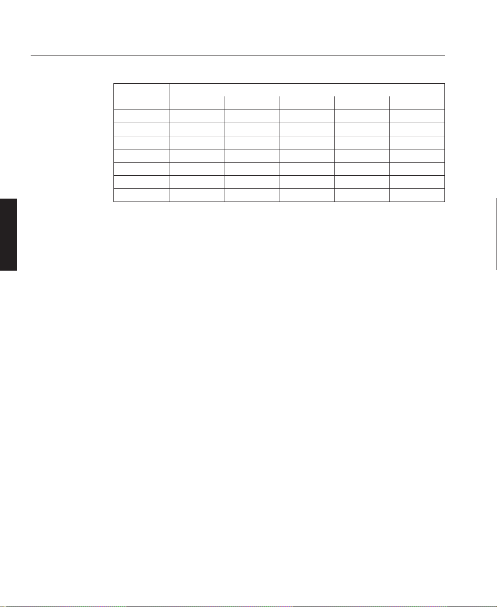
From time to time revisions will be issued to this manual. To maintain a correct and
up to date copy of the manual it is important that the instructions given in revision
notices are carried out.
The person carrying out the revision should complete the table below.
Revision No Revision Details Date Revised
Revision Record
LBV00072; Revision A - 25/09/2001
A
First Published
25 Sept 2001
Page 6

LBV00072; Revision A - 25/09/2001
Page 7

HIGHLite Displays are amongst the finest, most technically advanced projectors
available today.
Using state-of-the-art DLP™ technology by Texas Instruments, our projectors
deliver images with crystal clear clarity and sharper quality.
Your HIGHLite Displays projector enables you to project exceptionally bright, precise images up to 500 inches across (measured diagonally) from your PC or
Macintosh computer, VCR, document camera, laser disc player, DVD player and
even an HD VCR, HD laser disc player or video server.
Please read the following before proceeding
An Outline of Contents is given overleaf which provides an overview of the five
sections, A to E, in this manual and lists all the major topics covered along with
their location. This outline allows the user to direct themselves to the appropriate
section of this manual where a detailed contents page will provide the exact location
of the topic required. Section identifiers are also provided on the outside edge of the
pages to allow the quick location of individual sections.
The user is strongly recommended to read Section A: Overview before unpacking
or switching on the projector, paying particular attention to the safety warnings
provided.
Disclaimer Digital Projection makes a sincere effort to ensure accuracy and quality of it's published materials;
however, no warranty, expressed or implied, is provided. Digital Projection disclaims any direct or indirect damages
resulting from the use of any information in this manual.
DLP is a trademark of Texas Instruments Incorporated
Introduction
Introduction
INTRODUCTION
LBV00072; Revision A - 25/09/2001
Page 8

Digital Projection Limited,
Greenside Way, Middleton, Manchester M24 1XX, UK.
Registered in England No. 2207264, Registered Office: As Above
Tel: +44 (0) 161 947 3300
Fax:+44 (0) 161 684 7674
E-Mail:enquiries@digitalprojection.co.uk, service@digitalprojection.co.uk
Web Site:www.digitalprojection.co.uk
Digital Projection Inc.
55 Chastain Road, Suite 115, Kennesaw, GA 30144. USA
Tel: (USA) 770 420 1350
Fax: (USA) 770 420 1360
E-Mail: powerinfo@digitalprojection.com
Web Site: www.digitalprojection.com
Introduction
INTRODUCTION
LBV00072; Revision A - 25/09/2001
Page 9

Section A: Overview
Packaging .................................................................. A— 1
Safety Advice ............................................................. A— 2
Components ............................................................... A—5
Section B: System Installation
Installation Guidelines................................................. B—1
Installation .................................................................. B—7
Setting Up the Projector ............................................. B—11
Startup Screen (Language Select) ............................ B—13
Connecting Signal Sources........................................ B—15
Section C: System Operation
Remote Control Overview .......................................... C—1
Basic / Custom Menu .................................................. C—8
Menu System Overview ............................................. C—9
Menu Operation ....................................................... C—13
Source Select ............................................................ C—14
Adjust (Source) ......................................................... C—18
Ref Adj ...................................................................... C—30
Factory Default ......................................................... C—32
Projector Options ...................................................... C—33
PC Card Files ............................................................ C—42
Help .......................................................................... C—42
Test Pattern ............................................................... C—45
Introduction
Outline of Contents
INTRODUCTION
LBV00072; Revision A - 25/09/2001
Page 10

Section D: Advanced User Information
Screen Illuminance ..................................................... D—1
DMD™ Operation and Usage ..................................... D—2
Multiple Projection ...................................................... D—4
External Hardwired Control via Remote 1 Connector .. D—11
Projector Dimensions ................................................ D—12
Technical Specification ............................................. D—13
Section E: Maintenance
Lamp Replacement .................................................... E—1
Cleaning ..................................................................... E—2
Trouble Shooting ......................................................... E—3
Appendix
Glossary.............................................................................. i
Introduction
INTRODUCTION
LBV00072; Revision A - 25/09/2001
Page 11

Packaging ........................................................................ A—1
Projector Packaging.................................................... A—1
Lens Packaging........................................................... A— 1
Safety Advice ................................................................... A—2
Fire and Shock Precautions......................................... A—2
Lamp Precautions ....................................................... A—2
Power Supply ............................................................. A— 3
Installation Advice ..................................................... A— 4
Components ..................................................................... A—5
Part Names ................................................................. A—5
Control Panel ............................................................. A— 6
Terminal Panel ........................................................... A— 8
RGB Digital Connectors & Optional SDI Board ......... A—10
Remote Control ........................................................ A—13
Overview
Section A: Overview
OVERVIEW
LBV00072; Revision A - 25/09/2001
Page 12

Overview
OVERVIEW
LBV00072; Revision A - 25/09/2001
Page 13

Projector Packaging
The following components should be contained within the projector packaging.
Should any of the components be absent, please contact the dealer who supplied the
projector, or Digital Projection Limited (Digital Projection Inc. if in North
America) immediately.
1 x HIGHlite Displays Projector
1 x Remote Control Unit with Remote Cable (wireless/wired)
1 x AC Power Cable
1 x AC Power Cable Stopper
1 x DVI-D Cable
2 x AAA Batteries
1 x User Manual
1 x Foam Dust Cap
CompactFlash Memory Card (8MB) with adapter
All packaging should be retained to provide maximum protection during future
shipping of the projector.
Lens Packaging
Lenses are supplied as individual items and the packaging may differ depending on
the version ordered. Please refer to the instructions supplied with your lens.
A—1
Overview
Packaging
OVERVIEW
LBV00072; Revision A - 25/09/2001
Page 14

The safety instructions provided in this manual are to ensure the long life of your
projector and to prevent fire and shock. Please read them carefully and heed all
warnings.
Fire and Shock Precautions
Ensure that there is sufficient ventilation and that vents are unobstructed to prevent
potentially dangerous concentrations of ozone and the build-up of heat inside your
projector. Allow at least 20cm (8”) of space between your projector and a wall.
Allow at least 50cm (20”) of space between the ventilation duct outlet and object.
Ensure that nothing can be spilled on, or dropped inside the projector. If this does
happen, switch off and unplug the mains supply immediately. Do not operate the
projector again until it has been checked by qualified service personnel.
Do not insert any metal objects such as a wire or screwdriver into your projector.
Lamp Precautions
Due to the lamp being sealed in a pressurised environment, there is a small risk of
explosion, if not operated correctly. There is minimal risk involved, if the unit is in
proper working order, but if damaged or operated beyond the recommended 1500
hours, the risk of explosion increases.
The projector has a warning system that displays the following message when you
reach 1500 hours of operation - Lamp Running Time is Over 1500 Hours!!. When
you see this message please contact your Digital Projection dealer for a
replacement lamp.
If the lamp does explode, smoke will be discharged from the vents located on the
side of the unit. This smoke is comprised of glass in particulate form and Xenon
A—2
Overview
Safety Advice
OVERVIEW
LBV00072; Revision A - 25/09/2001
Page 15

gas, and will not cause harm if kept out of your eyes. If your eyes have been
exposed to this gas, please flush your eyes out with water immediately and seek
immediate medical attention. Do not rub your eyes as this could cause
serious injury.
WARNING: Do not look into the lens while the projector is on. Serious damage to
your eyes could result.
CAUTION: The high pressure lamp may explode if improperly handled. Refer all
servicing to qualified service personnel.
Power Supply
The projector is designed to operate on a power supply of 1.0kW 100-120VAC /
1.5kW 200-240VAC 50/60Hz. Ensure that your power supply fits this requirement
before attempting to use your projector.
Handle the power cable carefully and avoid excessive bending. A damaged cord can
cause electric shock or fire.
Running the power cord and the RGB cable close to each other can cause beat
noise. If this happens, keep the two separated so that beat noise is not generated.
If the projector is not be used for an extended period of time, disconnect the plug
from the power outlet. Do not unplug the power cable from the wall outlet under the
following circumstances, doing so may cause damage to the projector:
a) Immediately after the power cable is plugged into the wall outlet (the POWER
indicator has not changed to a steady amber glow).
b) Immediately after the lamp has been switched off. After the projector is turned
off with the POWER OFF button the cooling fan continues to operate for 3
minutes while the Two Digit INDICATOR "--" flashes.
c) While the hour glass icon or the message ‘Please wait a litttle’ is being displayed.
A—3
Overview
OVERVIEW
LBV00072; Revision A - 25/09/2001
Page 16

Installation Advice
The projector should be placed on a flat, level surface and in a dry area free from
dust and moisture. Do not place the projector in direct sunlight, near heaters or heat
radiating appliances as exposure to direct sunlight, smoke or steam could harm
internal components.
The projector should always be handled with care. Dropping or jarring the projector
could damage internal components.
Do not place heavy objects on the projector.
If you wish to have the projector installed on the ceiling do not attempt to install the
projector yourself. The projector must be installed in accordance with any local
building codes by qualified technicians in order to ensure proper operation and
reduce the risk of bodily injury.
The ceiling must be strong enough to support the weight of the projector.
Do not attempt to stack projectors on the ceiling.
A—4
Overview
OVERVIEW
LBV00072; Revision A - 25/09/2001
✍
✍
✍
Page 17
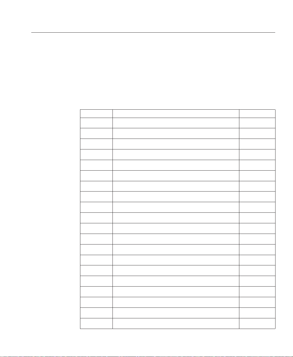
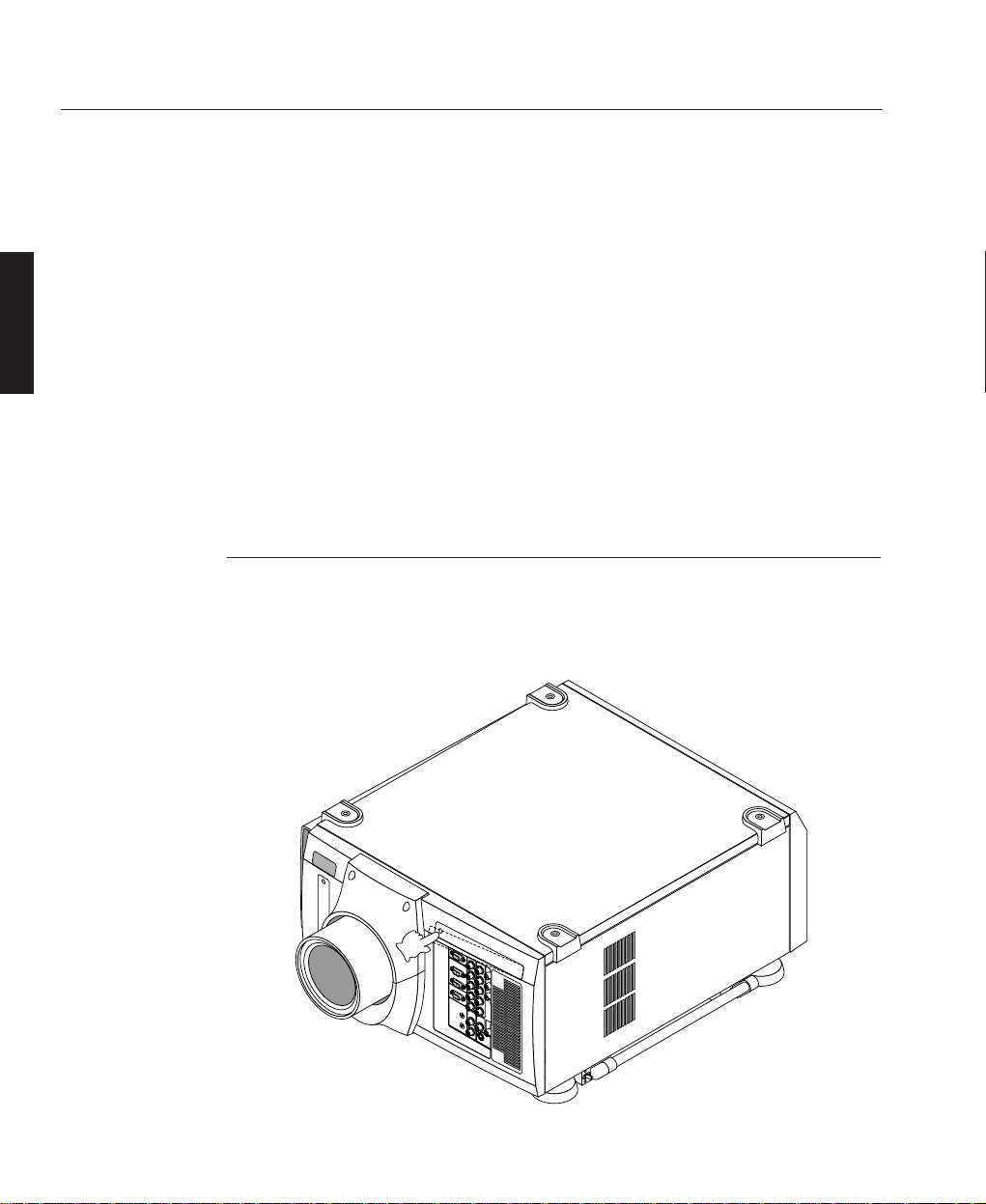
Part Names
A—5
0verview
Components
OVERVIEW
LBV00072; Revision A - 25/09/2001
Stacking Pad
Digital Input Terminal Panel
Remote Sensor
PC Card Slot
Lens (optional)
Input Terminal Panel
Ventilation (In)
Foot
Release Lever
Ventilation (Out)
Carrying Handle
Power Switch
AC Input
Ventilation (In)
Controls
Ventilation (In)
Ventilation (In)
Page 18
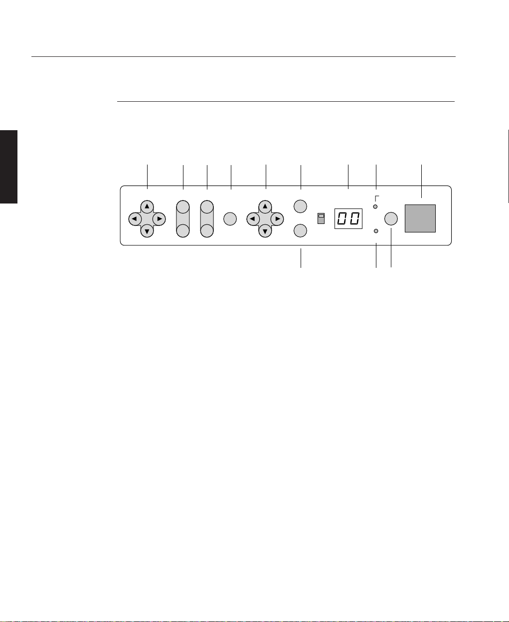
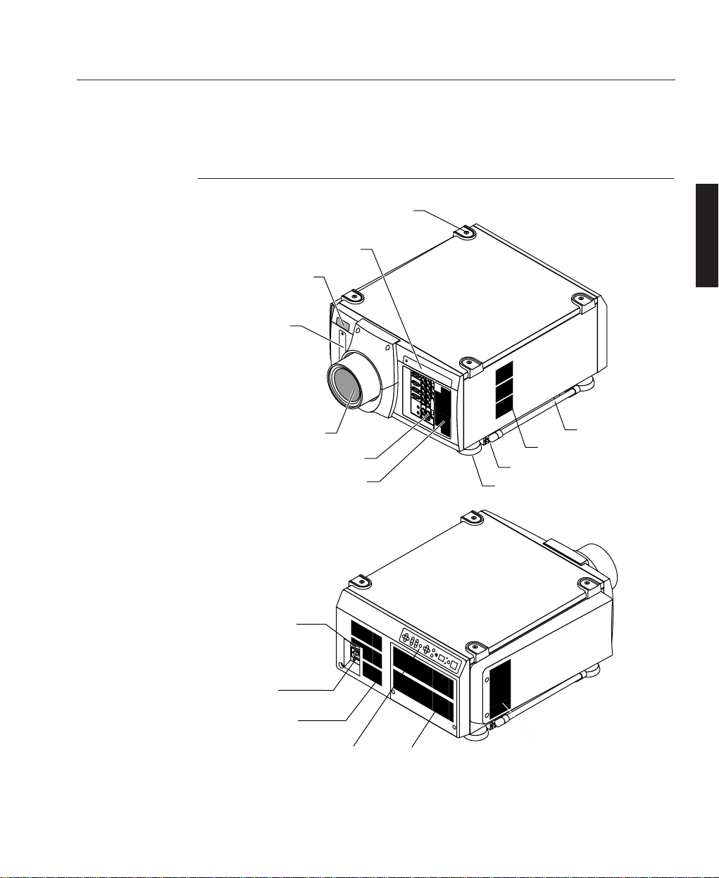
Control Panel
The control panel at the rear of the projector provides all the main controls
necessary to operate the projector.
1 - Power Button
Press to turn the projector on when the projector is in the standby condition (Main
Power switch must be on and the POWER indicator lit amber). Press and hold for 2
seconds to turn off the projector.
2 - Power LED
The power indicator is a dual colour LED. When the projector is on the indicator is
green. When the projector is in standby mode the indicator is amber.
After the projector is turned off, the indicator "--" flashes for three minutes to
show that the cooling fan is working. Do not turn off the main power during that
time. After "--" stops flashing, the POWER indicator will change to a steady
amber glow and the projector will be in the stand-by mode. The main power can
then be turned off.
3 - Status LED
When the projector is used with a configured switcher on SW1 level or SW2 level
mode, this indicator flashes when the projector is not connected with the switcher
correctly or when the switcher is turned off.
4 - Indicator Display
During normal operation the current projector ID (address) is shown in this two
digit display. In the event of an error, a projector error code will be displayed. The
display can be turned off using the ON/OFF Switch to the left hand side.
A—6
Overview
OVERVIEW
LBV00072; Revision A - 25/09/2001
8
POWER
LENS SHIFT
FOCUS
ZOOM INDICATORSELECT ENTER
CANCEL
STATUS
ON
OFF
MENU
-
+
ON/OFF
+
75
4 2 Remote Sensor910
11
6
13
✍
Page 19

5 - Enter Button
Executes your menu selection and activates items selected from the menu. When the
slidebar or dialog box is displayed: Pressing this button confirms adjustments/
setting and returns to the previous menu display.
6 - Cancel Button
Press this button to exit the menu. Press this button to return the adjustments to the
last condition while you are in the adjustment or setting menu.
7 - Select Cursor Buttons
The up & down cursor buttons are used to select the menu of the item you wish to
adjust and the left & right cursors change the level of a selected menu item.
8 - Menu Button
Activates the main menu.
9 - Zoom Button
Zoom the lens in and out.
10 - Focus Button
Adjust the lens focus.
11 - Lens Shift Cursor Buttons
Adjust the lens offset by shifting the projected image position horizontally and/or
vertically.
A—7
Overview
OVERVIEW
LBV00072; Revision A - 25/09/2001
Page 20
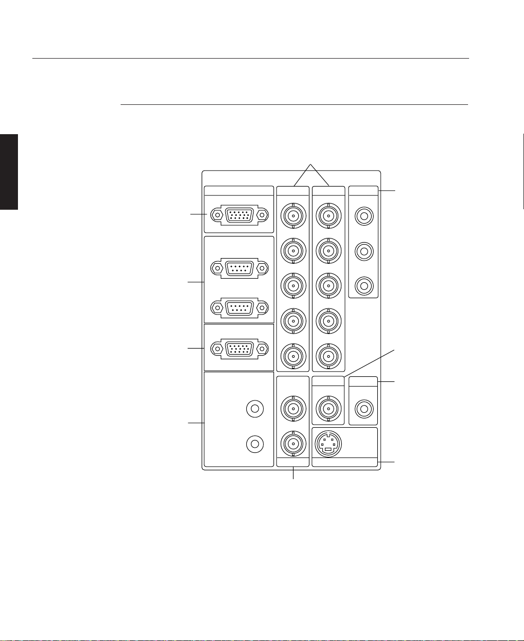
Terminal Panel
The Terminal Panel located at the front of the projector provides all the required
connections for video, computer and remote control.
1 - INPUT 3 (RGB3)
A Mini D-Sub 15 pin connector to allow connection of a PC or other analogue RGB
equipment such as a high-definition document camera.
2 - OPTION IN/OUT
Two Mini D-Sub 9 pin connectors for system expansion such as PC-control. The IN
A—8
Overview
OVERVIEW
LBV00072; Revision A - 25/09/2001
INPUT3
4
INPUT1
INPUT2 INPUT4
INPUT5
INPUT6
INPUT7
INPUT8
REMOTE2 S-VIDEO1
VIDEO1 VIDEO2
S-VIDEO2
IN
OUT
Y
C
REMOTE1
OPTION
IN
OUT
V
H/HV
B/Cb
G/Y
R/Cr
RGB
V
H/HV
B/Cb
G/Y
R/Cr
Cb
Y
Cr
5
1
2
3
7
6
9
10
8
Page 21

connection should be attached to the external control equipment such as PC. The
OUT connection provides for daisy-chaining multiple projectors and operating them
with the same external equipment. To daisy-chain projectors, connect the IN terminal of the second projector to the OUT connection of the first projector. A third projector would be connected to the second projector in the same manner and the procedure would be repeated until all the projectors are connected.
3 - REMOTE 1
This Mini D-Sub 15 pin terminal allows external control of the projector from either
a configured switcher or from an external control source. When the switcher is used,
connect to the REMOTE 1 terminal on the back of the switcher.
4 - REMOTE 2
Two 3.5mm stereo mini jack sockets allow direct wired connection to an individual
projector or a number of projectors. The IN connector allows direct connection of
the remote control unit. The OUT connector is used for daisy-chaining multiple projectors and operating them with the same remote control.
Plugging the cable into the projector will automatically disable the infra-red remote
receivers.
5 - INPUT 1 (RGB1) and INPUT 2 (RGB2)
Inputs with BNC terminals for connection of R, G, B, H and V outputs of external
equipment such as a switcher. If using a source with combined sync output, connect
it to the H/V terminal. The R, G, B terminals can also be used to connect component
video outputs (Y/Cb/Cr) of external equipment.
6 - INPUT 4 (Component (Y/Cb/Cr))
Inputs with RCA terminals for component video outputs (Y/Cb/Cr) of external
equipment such as DVD player.
This input accepts component signals only.
7 - INPUT 5 (VIDEO 1)
BNC composite video connection for external equipment such as a VCR or laser
disk player.
A—9
Overview
OVERVIEW
LBV00072; Revision A - 25/09/2001
✍
Page 22
8 - INPUT 6 (VIDEO 2)
RCA composite video connection for external equipment such as a VCR or laser
disk player.
9 - INPUT 7 (S-VIDEO 1)
Two BNC connectors allow for S-Video connection for use with external equipment
such as a VCR or laser disk player that have separate Y and C video outputs.
10 - INPUT 8 (S-VIDEO 2)
Mini-DIN-4pin S-video connection for external equipment such as a VCR. This
input allows switching between S2 and S1 VIDEO input modes. See the "S-Video
Mode Select" section for more information.
RGB Digital Connectors & Optional SDI Board
There is a compartment above the terminal board on the front of the projector for
RGB Digital connectors and the optional SDI board. The compartment is opened by
pushing the left side of the panel.
A—10
Overview
OVERVIEW
LBV00072; Revision A - 25/09/2001
Page 23
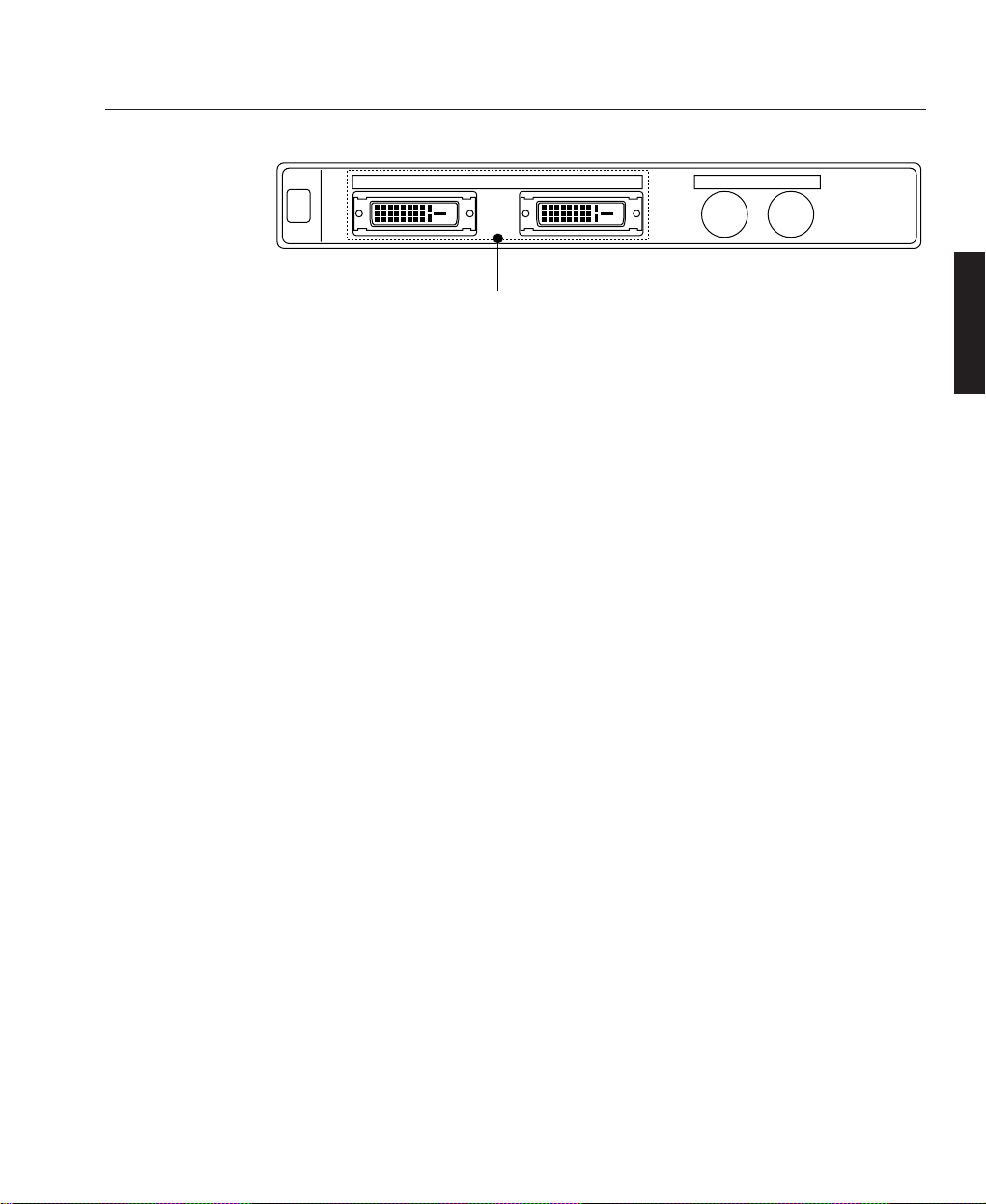
11 - INPUT 9 (RGB (Digital))
DVI-D 24 pin connectors for double or triple stacking. Use the supplied DVI-D
cable to connect the OUTPUT terminal of the first projector to the second projector's INPUT until all the projectors are connected.
The DVI-D cable must not exceed 5 m (16.4 feet) in length.
These connectors can also be used to accept TMDS standard digital signal output
from a digital ready computer. When used in this manner some
graphics cards may cause flickering noise on the screen.
The projectors support a maximum resolution of 1024x768 (4100gv and 5100gv)
or 1280x1024 (4000sx and 6000sx).
12 - INPUT 0 (SDI)
BNC SDI connection for use with equipment such as commercial type digital VTR.
Compatible with digital component signals complying with SMPTE 259M-C
standard.
4000sx and 6000sx models are also compatible with digital component signals complying with SMPTE 292M standard.
For further information on installing the optional SDI board contact your Digital
Projection Dealer.
A—11
Overview
OVERVIEW
LBV00072; Revision A - 25/09/2001
✍
✍
OUTPUT OUTPUT
RGB
DIGITAL
INPUT9 INPUT 0
SDI
11
Page 24

OPTIONALLY AVAILABLE SDI BOARDS
SDI Board (all models)
This board accepts the input of non-compressed signal sources from equipment such
as commercial type digital VCR compatible with digital serial component signals of
the SMPTE 259-C standard and provides a high quality image without quantisation
noise.
BNC cable used with the SDI connector should be Belden 8281 cable, or 3C-2V
equivalent cable or better.
Included in option:-
SDI Board Shield Case
Connector Cable (Internal) Installation Manual
HDSDI Board (sx models only)
This board accepts the input of non-compressed signal sources from equipment such
as commercial type digital VCR compatible with digital serial component signals of
the SMPTE 292M standard and provides a high quality image without quantisation
noise. This board accepts the following image formats.
1920 x 1035/60/2:1 30 2:1 Interlace
1920 x 1080/60/2:1 30 2:1 Interlace
1280 x 720/60/1:1 60 Progressive
1920 x 1080/24sF 24 Progressice (Segmented Frame)
BNC cable used with the HDSDI connector should be 5C-FB equivalnt cable or
better.
Included in option:-
SDI Board Shield Case
Connector Cable (Internal) (2) Flat Cable
Set screw for Shield Case (2) Installation Manual
A—12
Overview
OVERVIEW
LBV00072; Revision A - 25/09/2001
✍
✍
Page 25
Remote Control
All the functions of your HIGHlite Displays projector can be controlled using the
remote control. The remote control unit can operate either by infra red or by direct
connection to the projector via a hard wire connection.
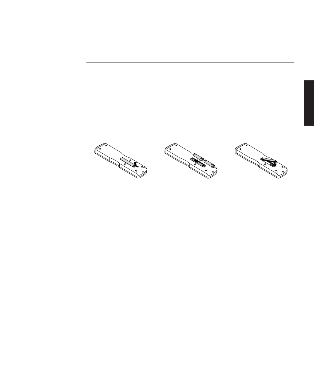
For infra red operation the remote control requires to be powered by 2 AAA
(HP16/RO3/LR03) alkaline batteries. The battery compartment is located on the
back of the remote control. To remove the compartment cover press and open as
shown below.
Insert the first battery into the compartment according to the (+) and (-) indications
inside the case and it to the back of the compartment. Insert the second battery by
pivoting it against the first and pushing down into place. When the batteries are
securely in place, replace the battery compartment cover.
When using infra red operation the remote control has an effective range of about
7m (23 feet) and at an angle of 30° above, below, to the left and to the right of the
remote control sensors located at the front and the rear of the projector.
The remote control should not be exposed to heat, steam, water or any other liquid.
If the remote control gets wet, wipe it dry immediately.
When remote control buttons are pressed and held down the main unit function
keys may not operate.
You cannot operate the projector using the remote control if the remote ID is not
set to [00] or the remote ID is not the same as the projector ID.
Very bright flourescent lighting or Infra Red translation systems may saturate the
projectors’ Infra Red receiver rendering the remote control inoperative.
A—13
0verview
OVERVIEW
LBV00072; Revision A - 25/09/2001
✍
✍
✍
Page 26

A—14
Overview
OVERVIEW
LBV00072; Revision A - 25/09/2001
Page 27

Installation Guidelines ...................................................... B—1
Screen Requirements ................................................... B
—1
Positioning the Projector .............................................. B
—4
Installation ....................................................................... B—7
Attaching the Power Cable Stopper ........................... B—7
Lens Installation .......................................................... B—8
Setting Up the Projector ................................................. B—11
Reflecting the Displayed Image ............................... B—12
Shutter Mechanism ................................................... B—12
Turning Off the Projector ........................................... B—12
Startup Screen (Language Select) ................................. B—13
Connecting Signal Sources ............................................ B—1 5
System Installation
Section B: System Installation
INSTALLATION
LBV00072; Revision A - 25/09/2001
Page 28

System Installation
INSTALLATION
LBV00072; Revision A - 25/09/2001
Page 29

This installation section explains how to install the projector for optimum results.
To do this, it is necessary to determine the following:
1. The type of screen and whether front or rear projection is to be used.
2. The projector location and therefore the type of lens to be used.
3. The method of mounting for the projector.
4. The type of input source to be used with the projector.
Screen Requirements
As virtually all commercially available screens will give a pleasing image you
should choose according to your individual requirements. However, to achieve
optimum results we recommend a low gain (1.2 - 1.3), non-perforated screen for
front projection, this will keep hot spotting and light loss to a minimum whilst
providing wide viewing angles.
Regardless of the type of screen used, it is important that your screen is of sufficient
height to display the images at the aspect ratios intended to be used. Use the
following tables to check that you are able to display the full image on your screen.
If you have insufficient height, you will have to reduce the overall image size in
order to display the full image on your screen.
B—1
System Installation
Installation Guidelines
INSTALLATION
LBV00072; Revision A - 25/09/2001
Screen Width
(metres)
2.40
3.00
3.60
4.20
4.80
6.00
10.00
4 x 3
1.80
2.25
2.70
3.15
3.60
4.50
7.50
5 x 4
1.92
2.40
2.88
3.36
3.84
4.80
8.00
8 x 5
1.5
1.87
2.25
2.62
3.00
3.75
6.25
14 x 9
1.54
1.93
2.31
2.70
3.09
3.86
6.43
16 x 9
1.35
1.69
2.02
2.36
2.70
3.38
5.63
Screen Height (metres) Needed to Display Full Image with Aspect Ratio:
Page 30
For optimum viewing, the screen should be a flat surface perpendicular to the floor.
The bottom of the screen should be 1.2m (4 feet) above the floor and the front row
of the audience should not have to look up more than 30° to see the top of the
screen (see opposite).
The distance between the front row of the audience and the screen should be at least
twice the screen height and the distance between the back row and the screen should
be a maximum of 8 times the screen height. The screen viewing area should be
within a 60° range from the face of the screen.
If you intend to use a rear projection screen you must ensure you have sufficient
distance behind the screen for the projector to be correctly located Rear projection
has the advantage that the projector cannot be seen and higher ambient light levels
can be tolerated. Although the image can be flipped to rear projection and displayed
without the need for extra mirrors or equipment, it makes the installation more
complicated and advice should be sought from your local dealer before attempting
an installation in this way.
B—2
System Installation
INSTALLATION
LBV00072; Revision A - 25/09/2001
Screen Width
(feet)
8' 0"
10' 0"
12' 0"
14' 0"
16' 0"
20' 0"
30' 0"
4 x 3
6' 0"
7' 6"
9' 0"
10' 6"
12' 0"
15' 0"
22' 6"
5 x 4
6' 5"
8' 0"
9' 7"
11' 2"
12' 10"
16' 0"
24' 0"
8 x 5
5' 0"
6' 3"
7' 6"
8' 9"
10' 0"
12' 6"
18' 9"
14 x 9
5' 2"
6' 5"
7' 9"
9' 0"
10' 8"
12' 10"
19' 4"
16 x 9
4' 6"
5' 8"
6' 9"
7' 11"
9' 0"
11' 4"
16' 11
Screen Height (feet/inches) Needed to Display Full Image with Aspect Ratio:
Page 31

B—3
System Installation
INSTALLATION
LBV00072; Revision A - 25/09/2001
1.2m (4 Ft)
H
30°
2H
SCREEN
2H8H
60°
VIEWING AREA
AISLE
AISLEAISLE
Page 32

Positioning the Projector
Correct positioning of the projector is essential to achieve the best results. Before
deciding on the final location of the projector please ensure you read the following
information very carefully.
The projector must be situated in a clean, dry environment and away from direct
sunlight or heat. Make sure you locate the projector so that the air inlets and
outlets for the cooling system are not obstructed.
When positioning the projector always carry it by the retractable handles provided.
The handles pull out from the bottom of the projector and click into place. To
retract the handles, push the securing lever to unlock and push back (see below).
Ensure that the power cord and any other cables connecting to video sources are
disconnected before moving the projector. When moving the projector or when it is
not in use, cover the lens with the lens cap.
PROJECTOR THROW DISTANCE
The further the projector is positioned from the screen or wall, the larger the
displayed image. The minimum projected image size is 2m (80") measured
diagonally. The largest the image can be is 12.7m (500").
B—4
System Installation
INSTALLATION
LBV00072; Revision A - 25/09/2001
✍
Page 33

When using a zoom lens, exact positioning of the projector is not required as the
image size can be adjusted. However, the projector must be located within the
Throw Distance range imposed by the minimum and maximum lens throw ratios.
To calculate the distance required between the screen and the projector select your
lens type and screen size from the table below.
Screen Size Throw Distance required for Lens Model
(Diagonal) LA00111, 0.84 LA00107, 1.5-2.5 LA00108, 2.5-4.0 LA00109, 4.0-7.0
80” 1.4 2.5 - 4.0 4.1-6.5 6.6-11.3
(4.48) (8.20 - 13.10) (13.45-21.33) (21.65-37.07)
100” 1.7 3.1 - 5.0 5.1 - 8.1 8.2 - 14.2
(5.60) (10.17 - 16.40) (16.73 - 26.57) (26.90 - 46.59)
200” 3.4 6.1 - 10.1 10.2 - 16.2 16.3 - 28.4
(11.20) (20.00 - 33.14) (33.46 - 53.15) (53.48 - 93.18)
300” 5.1 9.2 - 15.2 15.3 - 24.3 24.4 - 42.6
(16.80) (30.18 - 49.87) (59.20 - 79.72) (80.05 - 139.76)
400” 6.8 12.2 - 20.3 20.04 - 35.5 32.6 - 56.8
(22.40) (40.03 - 66.60) (66.93 - 116.47) (106.96 - 186.35)
500” 8.5 15.2 - 25.4 25.4 - 40.6 40.7 - 71.1
(28.00) (49.87 - 83.34) (83.33 - 133.20) (133.53 - 233.27)
Throw distances measured in metres and (feet)
LENS SHIFT
The default height for positioning the projector is at the centre of your screen.
However, you can set the projector above or below the centre and adjust the image
using the ‘Lens Shift’ facility to centre the image on the screen.
B—5
System Installation
INSTALLATION
LBV00072; Revision A - 25/09/2001
80"
500"
400"
200"
100"
300"
Page 34

As with vertical positioning, the default horizontal position of the projector is at the
centre of the screen. However, the projector can be mounted to the left or right of
image centre and the ‘Lens Shift’ function used to centre the image on screen. The
lens can be shifted within the shaded shown below using the normal projection
position as a starting point.
Screen Size 80” 100” 150” 200” 300” 400” 500”
H 1.6 (5.33) 2.0 (6.67) 3.0 (10.00) 4.0 (13.33) 6.1 (20.00) 8.1 (26.67) 10.2 (33.33)
V 1.2 (4.00) 1.5 (5.00) 2.3 (7.50) 3.0 (10.00) 4.6 (15.00) 6.1 (20.00) 7.6 (25.00)
H: Width of projected image, V: Height of projected image, Units: Metres (Feet)
B—6
System Installation
INSTALLATION
LBV00072; Revision A - 25/09/2001
Lens Shifted
Screen
Normal Projection
Top View
Lens Shifted
Screen
Normal Projection
Side View
(0.23H)
Normal
Projector
Position
0.41V
(0.30H)
0.24V
0.19H 0.28H
(0.50V)
(0.32V)
SX
(GV)
0.08H
Normal
Projector
Position
0.15V
0.08H
0.15V
Screen Width (H)
Screen Height (V)
Page 35

Attaching the Power Cable Stopper
The Power Cable Stopper is provided with the projector so that the cable cannot be
accidentally unplugged from the AC IN.
1. Lift up the wire stopper. Check it is fitted in correct holes for your cable.
2. Connect the Power Cable to the AC IN then lower the stopper to hold the power
cable.
B—7
System Installation
Installation
INSTALLATION
LBV00072; Revision A - 25/09/2001
For Europe
For North America
Page 36

Lens Installation
There are three zoom lenses available for the HIGHLite Displays projectors Model
numbers LA00107, LA00108 and the LA00109. These lenses have throw ratios of
1.5-2.5:1, 2.5-4.0:1 and 4.0-7.0:1 respectively. In addition to the zoom lenses a
fixed lens LA00111 is available with a throw ratio of 0.84:1.
Do not attempt to install a lens if the projector is turned on. If the projector is
operating, turn off the power and wait for the cooling fan to stop. Next turn off the
main power switch on the rear panel and wait for the projector to cool off.
INSTALLATION PROCEDURE
1. Remove the protective sponge from the lens hood.
2. Remove the two screws from the top of the upper lens hood.
3. Push the lower end to lift up and remove the upper lens hood.
4. Lift up the lower lens hood by 1 cm to release from the hook then remove
the hood.
B—8
System Installation
INSTALLATION
LBV00072; Revision A - 25/09/2001
Page 37

5. Remove the cap from the rear of the lens and insert the lens so that the three pins
on the lens unit are properly lined up with the holes on the projector.
Do not remove the front lens cap during lens installation. The lens cap helps
minimise any damage to the front lens element and prevents touching of the lens
surface which can degrade the optical performance.
6. Rotate the lens barrel clockwise to fix the lens unit.
7. Secure the three screws on the lens holder.
8. Insert the connector of the lens unit into the socket of the extension cable
attached to the projector.
B—9
System Installation
INSTALLATION
LBV00072; Revision A - 25/09/2001
✍
Page 38

9. Insert the lower lens hood into the retaining hook and secure.
10.Re-attach the upper lens hood while pushing the left and right bottom.
11.Secure the upper lens hood with two screws through the top of the hood.
12. Attach the foam sealing ring.
13. Remove the front lens cap.
B—10
System Installation
INSTALLATION
LBV00072; Revision A - 25/09/2001
Page 39

This section describes how to select a computer or video source, adjust the picture
edit a signal and adjust all other settings and adjustments for correct projector
set-up.
Before you turn on the projector ensure that the computer or video source is turned
on and that the projector lens cap is removed.
Plug the supplied power cable into the AC outlet and turn on the projector with the
main power switch on the rear panel of the projector. The projector will go into its
standby mode and the POWER indicator will glow amber.
Press the ‘POWER ON’ button on the remote control or projector cabinet. The
POWER light will turn to green and the projector will fully turn on.
The projector will display a black, blue image or logo if no input signal is present.
To select the desired source press the ‘INPUT’ button on the remote control or press
the MENU button and use the Source Select function.
Adjust the projector position so that it is square to the screen and the displayed
image is horizontally centred. Next, adjust the vertical position of the projected
image using the Lens Shift Control.
Adjustments to the displayed image can be made using the ADJUST PICTURE or
ADJUST WHITE BAL buttons on the remote control or via the Adjust (Source)
option from the Main Menu.
If projecting an image with lower resolution than the projector's native resolution
(1024x768 (gv) or 1280x1024 (sx)), the image can be enlarged to fill the screen by
selecting Native the Resolution window.
While pressing and holding CTL, press MAGNIFY or FOCUS on the remote
control to zoom the lens or adjust the lens focus.
B—11
System Installation
Setting Up the Projector
INSTALLATION
LBV00072; Revision A - 25/09/2001
Page 40

Reflecting the Displayed Image
Using a mirror to reflect your projector's image enables you to obtain a much larger
image in a much smaller space. If the image is inverted when using a mirror, it can
be corrected using the Orientation feature under Setup in the Projector Options
Sub-menu. For further details contact your dealer or Digital Projection.
You can use your HIGHlite Displays projector to project an image from the rear onto
a translucent screen. The throw distance required for rear projections is the same as
for front projection. If the image is inverted when projecting an image from the rear,
it can be corrected using the Orientation feature under Setup in the Projector
Options Sub-menu. For further details contact your dealer or Digital Projection.
Shutter Mechanism
Your HIGHlite Displays projector is equipped with a mechanical shutter which
allows the user to shut off the light completely on the screen. To use the shutter
function, hold down the CTL button, and press the MUTE PICTURE button on the
remote control
Turning Off the Projector
In order to extend the life of the lamp the projector should be turned off as
described below. Press the POWER OFF button on the remote control or the projector cabinet and allow the fan to cool the projector for three minutes. After the cooling fan stops working the POWER indicator will change to a steady amber glow
and the projector will be in the stand-by mode. The projector can now be turned off
using the main power switch on the rear panel. If the projector is not going to be
used for an extended period it should be disconnected from the mains supply. Do
not turn the projector off and then immediately back on. The Projector needs to cool
down for three minutes before it is powered on again. If you want to turn off the
image briefly (five minutes or less) use the MUTE PICTURE feature.
Do not turn off the main power while the cooling fan is working.
B—12
System Installation
INSTALLATION
LBV00072; Revision A - 25/09/2001
✍
Page 41

When you first turn on your Highlite Displays projector you will get the startup
screen.
This screen gives you the opportunity to select one of the seven menu languages:
English, German, French, Italian, Spanish, Swedish and Japanese.
Use the cursor movement button to highlight the desired language and press
ENTER to select.
B—13
System Installation
Startup Screen (Language Select)
INSTALLATION
LBV00072; Revision A - 25/09/2001
+
-
MENU
ENTER
+
-
MENU
ENTER
Page 42

To close the menu without making a selection or to save your language selection,
press the CANCEL button.
To select or change the language later press MENU and navigate to ‘Projector
Options’ - ‘Menu’ - ‘Page1’ - ‘Language’ and follow the above instructions.
B—14
System Installation
INSTALLATION
LBV00072; Revision A - 25/09/2001
CANCEL
Page 43

CONNECTING A VIDEO RECORDER OR LASER DISC PLAYER
Video recorders and laser disc player connect to the HIGHlite Displays Projector
using common RCA cables (not provided). To make these connections, simply:
Connect one end of your RCA cable to the video output connector on the back
of your video recorder or laser disc player and the other end to the Video input
on your projector.
Refer to your VCR or laser disc player owner's manual for more information
about your equipment's video output requirements.
CONNECTING A COMPUTER
Connecting your PC or Macintosh computer to the HIGHlite Displays Projector will
enable you to project your computer's screen image for an impressive presentation.
To connect to a computer:
Use the signal cable supplied with the PC or Macintosh computer to connect to
the projector.
If the projector goes blank after a period of inactivity, it may be caused by a
screen saver installed on the computer.
CONNECTING A DOCUMENT CAMERA
To connect your HIGHlite Displays Projector to a document camera simply:
Using a standard video cable, connect your document camera to the Video input
(or INPUT3, RGB) on your projector.
Refer to your document camera's owner's manual for more information about
your camera's video output requirements.
B—15
System Installation
Connecting Signal Sources
INSTALLATION
LBV00072; Revision A - 25/09/2001
✍
✍
✍
Page 44

B—16
System Installation
INSTALLATION
LBV00072; Revision A - 25/09/2001
Page 45

Remote Control Overview ............................................... C—1
Direct Key Combinations ........................................... C—7
Basic/Custom Menu......................................................... C—8
Menu System Overview ................................................... C—9
Navigating the Menu System .................................. C—10
Menu Structure ......................................................... C—11
Menu Operation ............................................................. C—13
Main Menu ............................................................... C—13
Source Select .................................................................. C—14
Entry List ................................................................... C—15
Adjust (Source)................................................................ C—18
Picture ....................................................................... C—18
White Balance .......................................................... C—20
Image ....................................................................... C—21
Video Adj .................................................................. C—24
Option Adj ................................................................ C—26
Lens Memory............................................................. C—27
Signal Type ............................................................... C—29
System Operation
Section C: System Operation
OPERATION
LBV00072; Revision A - 25/09/2001
Page 46

Ref Adj............................................................................. C—30
Keystone ................................................................... C—30
Lamp ........................................................................ C—31
Ref. White Bal. ........................................................... C—31
Factory Default .............................................................. C—32
Projector Options ........................................................... C—33
Timer ......................................................................... C—33
Menu ........................................................................ C—35
Setup ......................................................................... C—37
Link Mode ................................................................. C—41
Switcher Control ....................................................... C—41
PC Card Files .................................................................. C—42
Help ................................................................................ C—42
Test Pattern .................................................................... C—45
System Operation
OPERATION
LBV00072; Revision A - 25/09/2001
Page 47

All the functions of a HIGHLite Displays projector can be controlled by the remote
control unit. The remote control can be directly connected to the projector via a
control cable or to provide more flexibility send infra red signals which are detected
by sensors located at the front and rear of the projector.
A description of all the remote control functions is provided overleaf.
C—1
System Operation
Remote Control Overview
OPERATION
LBV00072; Revision A - 25/09/2001
OFF
+
-
PICTURE
ADJUST
ABC DEF
GHI
JKL MNO PQR
STU
,.
UNDO CANCEL
TEST
PICTURE
KEYSTONE AMPLITUDE ENTRYLIST
SOUND OSD
MUTE
MAGNIFY
HELPINFO.
POSITION AUTOPIXEL
VWX YZ/
WHITE BAL.
IMAGE
ON
POWER
MENU
ENTER
123
456
7
0
8
9
ADDRESS
PROJECTOR
R G B
LENS
SHUTTER
BS
+
-
+
-
FOCUS ZOOM
CTL
LENS
2
5
6
7
9
10
12
13
17
20
21
22
24
26
25
23
19
18
16
15
14
11
8
4
3
1
Page 48

1 - POWER ON
Press to turn on the projector. The POWER indicator on the projector lights up
green.
2 - POWER OFF
Press and hold this button for a minimum of 2 seconds to turn off the projector.
3 - MENU
Press to display the main menu.
While pressing and holding CTL, press this button to display the Remote Control
ID dialog box to specify the remote control ID.
4 - ENTER
Executes the menu selection and activates items selected from the menu.
When the slidebar or dialog box is displayed:
Pressing this button confirms adjustments / settings and returns to previously displayed menu.
5 - CURSOR (Up / Down / Left / Right)
Moves the highlighted menu selection as indicated.
When pressed together the CTL and < buttons work as a backspace key in the entry
screen.
Pressing and holding CTL, then this button moves the menu, slidebar or dialog box
in the indicated direction on the displayed image.
6 - ADJUST WHITE BAL
Press to display the Colour adjustment screen. Sequential presses of this button
selects “Colour Temperature” - “White Balance - Brightness” - “White Balance Contrast” - “Signal Level” - “Ref. White Bal” - “Switcher Gain”
7 - ADJUST PICTURE
Press to display the Picture adjustment screen. Sequential presses of this button
selects “Brightness” - “Contrast” - “Saturation” - “Colour” - “Hue” - “Sharpness” “V-Aperture” - “Gamma Correction”
C—2
Overview
OVERVIEW
LBV00072; Revision A - 25/09/2001
Page 49

8 - IMAGE / PROJECTOR
Press to display the Image Option screen. Sequential presses of this button selects
“Pixel Adjust” - “Position” - “Aspect Ratio” - “Resolution” - “Overscan” - “Video
Filter” - “Blanking”.
While pressing and holding CTL, sequentially pressing this button selects “On/Off
Timer” - “Sleep Timer” - “Menu” - “Setup” - “Link Mode” - “Switcher Control”.
9 - INPUT
Use to select an input, to name a signal or to enter a passcode during input registration.
1 - INPUT 1 for RGBHV / Y, Cr/Pr, Cb/Pb
2 - INPUT 2 for RGBHV / Y, Cr/Pr, Cb/Pb
3 - INPUT 3 for RGB
4 - INPUT 4 for Y, Cr/Pr, Cb/Pb
5 - INPUT 5 for VIDEO 1
6 - INPUT 6 for VIDEO 2
7 - INPUT 7 for S-VIDEO 1
8 - INPUT 8 for S-VIDEO 2
9 - INPUT 9 for RGB DIGITAL input
0 - INPUT 0 for SDI input on the optional SDI board
10 - UNDO
Press to return the adjustments and settings to the previous condition.
While pressing and holding CTL use this button to clear all menus or adjustment/
setting screen. At this time the adjustments/settings are stored in memory.
11 - CANCEL
Press this to exit to the previous menu.
While pressing and holding CTL use this button to make the previous menu active
without exiting the current menu. This feature allows you to adjust several items
concurrently.
12 - INFO
Displays the “Source Information” or “Projector Information” window.
This button toggles between these two windows.
C—3
0verview
OVERVIEW
LBV00072; Revision A - 25/09/2001
Page 50

13 - TEST
Press to display internal test pattern.
Sequential presses scroll through series of five test patterns.
14 - HELP
Provides on line help.
15 - PIXEL
Displays the Pixel Adjust screen to adjust pixel clock and phase.
16 - AUTO (RGB only)
Press to automatically adjust Position-H/V and Pixel Clock for optimal picture.
The Pixel Phase is not adjusted.
17 - POSITION
Press to display the Blanking screen; press again to display the position screen.
While pressing and holding CTL, press this button to display the Lens Shift adjustment screen.
18 - MUTE SOUND
(available only when using a configured switcher)
Turns off the sound for a short period of time. Press again to restore the sound.
19 - MUTE OSD
Press to turn off the on-screen menu display. Press again to restore the on-screen
display.
You can also turn off the on-screen display by pressing and holding the CTL and
then pressing MUTE OSD; doing this again restores it. It this case any adjustment will still change the projector’s memory settings. This mode is available even
when an input is switched to another or if the power is turned off using the
POWER OFF button on the remote control.
C—4
Overview
OVERVIEW
LBV00072; Revision A - 25/09/2001
✍
✍
Page 51

20 - MUTE PICTURE
Press to turn off the picture for a short period of time. Press again to restore the picture. Pressing and holding CTL, then pressing this button closes the light shutter
such that no light is emitted through the projection lens.
21 - KEYSTONE (R)
Press to display the Keystone Correction screen.
22 - AMPLITUDE (G)
Service personnel only.
23 - ENTRY LIST (B)
Press to display the Entry List screen.
24 - FOCUS (+/-)
While pressing and holding CTL, pressing this button allows you to adjust the lens
focus.
25 - MAGNIFY/ZOOM (+/-)
Magnify the size of a target portion.
While pressing and holding CTL, pressing this button allows you to zoom the lens
in and out.
26 - CTL
Used in conjunction with other buttons, similar to a shift key on a computer keyboard.
C—5
0verview
OVERVIEW
LBV00072; Revision A - 25/09/2001
Page 52

27 - INFRARED TRANSMITTER
Direct the remote control toward the remote sensor on the projector cabinet.
28 - REMOTE JACK
Connect your remote control cable here for wired operation.
C—6
Overview
OVERVIEW
LBV00072; Revision A - 25/09/2001
OFF
+
-
PICTURE
ADJUST
ABC DEF
GHI
JKL MNO PQR
STU
,.
VWX
WHITE BAL.
IMAGE
ON
POWER
MENU
ENTER
123
456
7
0
8
ADDRESS
PROJECTOR
BS
28
27
Page 53

Direct Key Combinations
The CTL button can be used in conjunction with other remote control buttons to
provide alternative functions. A list of these combinations is provided below.
KEY COMBINATION ACTION
CTL + INPUT (1-10) Switches to selected signal found in the Entry List.
To enable this combination, you must first assign
specific remote keys for direct input selection in
the Entry Edit window.
CTL + ENTER Displays the Entry Edit Command Window. Only
available while displaying the Entry List window.
CTL + MUTE PICTURE (SHUTTER) Blocks all projector light output.
CTL + CANCEL Returns to previous menu without closing the
slidebar or dialogue box.
CTL + UNDO Clears all menus or adjustment/setting screens.
Adjustments & settings are saved automatically.
CTL + Cursor Button Moves the slidebar or dialogue box horizontally
or vertically.
CTL + Cursor Button (while using zoom) Displays the magnifying glass icon.
CTL + Left Cursor (BS) Deletes one letter or numeral in the entry screen.
CTL + TEST Displays the Passcode Entry screen.
CTL + MENU (ADDRESS) Displays the Remote ID Entry window.
CTL + IMAGE (PROJECTOR) Sequentially selects the Projector Options sub
menus.
CTL + POSITION (LENS) Displays the Lens Shift control window.
CTL + KEYSTONE (R) Turns on Red. Only available when viewing Test
Patterns.
CTL + AMPLITUDE (G) Turns on Green. Only available when viewing
Test Patterns.
CTL + ENTRY LIST (B) Turns on Blue. Only available when viewing Test
Patterns.
CTL + MAGNIFY (ZOOM) Zooms the lens in and out.
CTL + (FOCUS) Adjusts the lens focus.
CTL + INFO Saves Lens Zoom and Focus position.
C—7
0verview
OVERVIEW
LBV00072; Revision A - 25/09/2001
Page 54

The Basic/Custom menu can be customised to meet your requirements.
Select ‘Projector Options’ - ‘Menu’ - ‘Page1’ - ‘Basic/Custom Menu Edit’ to display the menu editing screen.
Highlight your desired selection and press the ENTER button to place a check mark
next to the option.
If you select an item with a solid triangle and press the ENTER button all submenu
items will also be selected.
You can press the ENTER button again to clear a check mark.
Up to 12 main items (not including submenu items) can be selected for display.
To finalise your selection navigate to the OK button and press the ENTER button.
You will then be asked to confirm the changes.
All items not selected can still be accessed by selecting ‘To Advanced Menu’ item
in the Main Menu.
C—8
Overview
Basic/Custom Menu
OPERATION
LBV00072; Revision A - 25/09/2001
Page 55

Slide Bar
Menu windows or dialog box typically have the following elements:
Title bar - Indicates the menu title.
Highlight - Indicates the selected menu or item.
Solid triangle - Indicates further choices are available. A highlighted triangle
indicates the item is active.
C—9
Overview
Menu System Overview
OPERATION
LBV00072; Revision A - 25/09/2001
Radio Button
Title Bar
Tab
Highlight
Check Box
Cancel Button
Solid Triangle
OK Button
Page 56

✍
Tab - Indicates a group of features in a dialog box. Selecting any tab brings its page
to the front.
Radio button - Use this round button to select an option in a dialog box.
Check box - Place a checkmark in the square box to turn the option On.
Slide bar - Indicates settings or the direction of adjustment.
OK button - Press to confirm your setting. You will return to the previous menu.
Cancel button - Press to cancel your setting. You will return to the previous menu.
Navigating the Menu System
Press the MENU button on the remote control to display the Main Menu. Next, use
the up and down cursor buttons on the remote control to select the required sub
menu and press ENTER.
Using the up and down cursor buttons to select the item to be modified from the sub
menu and press ENTER to display the adjustment screen or dialog box.
A right-oriented delta symbol in the menu structure indicates that further
choices are available by pressing the right cursor button.
Adjust the level or turn the selected item on or off using left or right cursor keys on
the remote control. The on-screen slide bar will show you the amount of increase or
decrease.
To exit, press CANCEL on the remote control.
The change is stored automatically when the on-screen display disappears, the
projector goes into standby mode or one input is switched to another.
C—10
Overview
OPERATION
LBV00072; Revision A - 25/09/2001
✍
Page 57

Menu Structure
C—11
Overview
OPERATION
LBV00072; Revision A - 25/09/2001
0 – 100
NTSC, Graphics NTSC, PAL/SECAM2.8,
PAL/SECAM, Natural 1/Natural 2
Advanced Menu
Source Select
Adjust (Source)
Ref Adj
Factory Default
Projector Options
Help
Test Pattern
RGB1
RGB2
RGB3
Component (YCbCr)
Video1
Video2
S-Video1
S-Video2
RGB (DIGITAL)
SDI
Entry List
Switcher
Entry List
When Switcher Control is
turned on:
Stand alone
Brightness
Contrast
Saturation
Color
Hue
Sharpness
V-Aperture
Gamma Correction
Color Temperature
Brightness
Contrast
Signal Level
Pixel Adjust
Position
Aspect Ratio
Resolution
Overscan
Video Filter
Blanking
Noise Reduction
Color Matrix
Y/C Deray
Telecine
Motion Select
Motion Level
YTR Adjustment
CTR Adjustment
Clamp Timing
Sync Protection
VD Delay
Gain
Volume
Reference / Custom
RGB / Component
Picture
White Balance
Image
Video Adj
Option Adj
Lens Memory
Signal Type
Switcher
Brightness R/G/B
Contrast R/G/B
Clock / Phase
Horizontal / Vertical
Input Signal 1.25:1 / 1.33:1 / 1.78:1 / 1.85:1 / 2.35:1
Display Area 1.25:1 / 1.33:1 / 1.78:1 / 1.85:1 / 2.35:1
Auto / Native
0% / 5% / 10% / 25%
On / Off Top / Bottom
Luminance Off / Low / Medium / High
Chrominance Off / Low / Medium / High
Select Color Matrix HDTV / SDTV
Delect Color Matrix Type B-Y/R-Y, U/V, Cb/Cr
Pb/Pr, IVX
Auto / Off
Still / Adaptive
Auto / Tri-Sync / Front Porch / Adjust
Red / Green / Blue
Page 58

C—12
Overview
OPERATION
LBV00072; Revision A - 25/09/2001
SX6000: Auto / High-Bright / Variable SX4000: Auto / Variable
Advanced Menu
Source Select
Adjust (Source)
Ref Adj
Factory Default
Projector Options
Help
Test Pattern
All Data / Current Signal
Including Entry List
Keystone
Lamp
Ref. White Bal.
Contents
Source Information
Projector Information
Lamp Mode
Lamp Output
Brightness R/G/B, Contrast R/G/B
Standalone / Master / Slave
Standalone / SW 1 Level / SW 2 Level
Contents
Cross Hatch, Gray Bars
Black Raster, Gray Raster
White Raster
Red / Green / Blue
Page 1
Page 2
Page 3
Source Name / Input Terminal / Entry No. / Horizontal Frequency /
Vertical Frequency / Sync Polarity
Signal Type / Video Type / Sync Type / Interlace / Resolution / Direct Key
Aspect Ratio (I) / Aspect Ratio (D) / Gamma Correction / Noise Reduction (L) /
Noise Reduction (C) / Color Matrix / Matrix Type
Page 1
Page 2
Menu Mode (Basic/Custom Menu, Advanced Menu, Service Menu)
Basic/Custom Menu Edit
Language (English / German / French / Italian / Spanish / Swedish / Japanese)
Menu Display Time (Manual / Auto 5 sec / Auto 10 sec / Auto 30 sec)
Display Select (Date, Time, Input Terminal, Source Name, Projector ID, On/Off)
Date Format
(MM/DD/YYYY, MM/DD/YYYY ddd, DD/MM/YYYY, DD/MM/YYYY ddd
YYYY/MM/DD, YYYY/MM/DD ddd, Month DD, YYYY, Month DD, YYYY ddd)
Date, Time Preset
On / Off Timer
Sleep Timer
Timer
Menu
Setup
Link Mode
Switcher Control
Execute Switch (Active / Inactive)
Edit
Preset Time (Off / 0:30 / 1:00 / 1:30 / 2:00)
Page 1
Page 2
Page 3
Page 4
Page 5
Orientation (Desktop Front / Ceiling Rear / Desktop Rear / Ceiling Front)
Background (Blue / Black / Logo)
S-Video Mode Select (Off / S2)
Signal Select
RGB 1 (Auto / RGB / Component)
RGB 2 (Auto / RGB / Component)
Sync Termination
RGB 1 (Hi-Z / 75Ω)
RGB 2 (Hi-Z / 75Ω)
Signal Select
Video 1 (Auto / NTSC3.58 / NTSC4.43 / PAL PAL60 / SECAM)
Video 2 (Auto / NTSC3.58 / NTSC4.43 / PAL PAL60 / SECAM)
S-Video 1 (Auto / NTSC3.58 / NTSC4.43 / PAL PAL60 / SECAM)
S-Video 2 (Auto / NTSC3.58 / NTSC4.43 / PAL PAL60 / SECAM)
Switcher (Auto / NTSC3.58 / NTSC4.43 / PAL PAL60 / SECAM)
Auto Adjust (RGB Only)
Power Management
Power Off Confirmation
Keystone Save
Doubler
Lens Memory
User Name
Communication Speed (4800 / 9600 / 19200 / 38400)
Projector ID (Enable / Disable) 1 – 64
Default Source Select (Last / Select)
Standalone
(RGB1 / RGB2 / Component (YCbCr) / Video1 / Video2 / S-Video1 /
S-Video2 / RGB (DIGITAL)
SW 1 Level (Slot 1 – 10)
SW 2 Level (M-01 S-01 – M10 S-10)
Page 1
Page 2
Page 3
Page 4
User Name / Serial Number / Lamp Hour Meter / Projector Usage / Projector ID
Version (BIOS / Firmware / Data / SUB-CPU)
Formatter Version (CPU / PROM / Prism)
FPGA Version (OSD / JOE)
Link Mode (Master / Slave)
Page 59

Main Menu
The Main Menu provides access to sub-menus which allow you to control the
projector and to view any system settings.
Source Select - enables selection of an input source.
Adjust (Source) - provides access to the image controls.
Ref Adj - provides access to Keystone, Lamp and Reference White settings.
Factory Default - takes you to the Factory Default options menu.
Projector Options - enables you to set projector options and other operating
options
PC Card Files - provides access to files stored on CompactFlash Card.
Help - provides on-line help.
To Advanced Menu - gives access to the advanced level menus.
C—13
System Operation
Menu Operation
OPERATION
LBV00072; Revision A - 25/09/2001
Page 60

Source Select enables you to select an input source connected to the projector.
To select an input source use the up/down buttons on your remote control or the
projector cabinet to highlight the desired input type and press Enter. Available
options include: RGB1, RGB2, RGB3, Component (YCbCr), Video1, Video2,
S-Video1, S-Video2, RGB Digital or SDI.
Alternatively Entry List may be selected which contains a list of the entry signals.
When in the Entry List window, use the up/down buttons on your remote control or
the projector cabinet to select the desired signal and press the Enter button.
When switcher control is turned on selecting Source Select will provide you with
options of selecting a Switcher input or selecting a signal from the Entry List.
C—14
System Operation
Source Select
OPERATION
LBV00072; Revision A - 25/09/2001
Page 61

Entry List
The Entry List window contains a list of all current and previously connected input
signals.
ENTRY EDIT COMMAND
The names and positions of the signals stored in the entry list can be modified using
the Entry Edit Command. To display the Entry Edit Command window hold down
CTL and press ENTER on the remote control. You can then Cut, Copy, Paste and
Edit the entries.
Cut - allows you to remove a selected signal from the list. The selected signal is
stored on the ‘clipboard’ in the projector.
Copy - copies the selected signal from the list and stores it on the ‘clipboard’.
Paste - Enables you to paste the signal stored on the ‘clip-board’ to any other line of
the list. To do this, select Paste and then select the line number you want to paste to
and press ENTER.
Edit - allows you to change source name or assign the direct key.
C—15
System Operation
OPERATION
LBV00072; Revision A - 25/09/2001
Page 62

The source name and input terminals can be modified by selecting “Source Name”
and “Input Terminal”. The appropriate Edit window will be displayed allowing you
to make adjustments, This option is only available for sources which are not being
currently being displayed.
You can assign specific remote keys for direct signal input selection using the
‘Direct Key’ function. Select ‘List’ and press ENTER to display the Direct Key
assignment list.
After assigning the desired remote keys, select ‘OK’ and press ENTER to save
changes and close the window.
C—16
System Operation
OPERATION
LBV00072; Revision A - 25/09/2001
Page 63

After modifying an entry in the list using the Edit function select OK and press
ENTER to save the new settings. To exit without storing setting, select Cancel.
To close the List window without making any changes press CANCEL on the
remote control.
One feature of HIGHLite Displays is the automatic creation of a new entry in the
Entry List when a new source is modified using picture controls such as
brightness etc. If many different sources are used with the projector it is
theoretically possible to fill the 100 entries available in the Entry List. If this
occurs, in the worst case the projector may not be able to display an image.
Therefore it is recommended that the Entry List is periodically cleared out,
deleting any unwanted RGB signals using the Cut command in the Entry Edit
Command menu.
C—17
System Operation
OPERATION
LBV00072; Revision A - 25/09/2001
✍
Page 64

The Adjust (Source) Menu provides access to the image controls. Use the up and
down cursor buttons on your remote control or the projector cabinet to highlight the
menu item you want to adjust.
Picture
The Picture Menu provides access to the Brightness, Contrast, Colour, Hue.
Sharpness and V-Aperture parameters of the displayed image. Each image
parameter is controlled by a slide bar.
C—18
System Operation
Adjust (Source)
OPERATION
LBV00072; Revision A - 25/09/2001
Page 65

Brightness - Adjusts the brightness level or the back raster intensity.
Contrast - Adjusts the intensity of the image according to the incoming signal.
Color - Increases or decreases the color saturation level (not available for RGB).
Hue - Varies the color level from +/- green to +/-blue. The red level is used as refer-
ence. This adjustment is only valid for Video and Component inputs (Not available
for RGB).
Sharpness - Controls the detail of the image for Video (Not available for RGB and
Component).
V-Aperture - Adjusts edge enhancement in the vertical direction. (Not available for
RGB).
Gamma Correction - Allows the selection from a list of appropriate gamma corrections to match the video type being input.
Natural 1 setting is for Video and S-Video
Natural 2 setting is for component video (Gamma = 2.2)
C—19
System Operation
OPERATION
LBV00072; Revision A - 25/09/2001
Page 66

White Balance
This feature adjusts the white balance for each input signal.
For Video/RGB signals the brightness for each color (RGB) is used to adjust the
black level of the screen and the contrast for each color adjusts the white level of
the screen.
For Y/Cb/Cr the brightness for each color (Y/Cb/Cr) is used to adjust the white
level of the screen and the contrast for each color is used to adjust the black level of
the screen.
C—20
System Operation
OPERATION
LBV00072; Revision A - 25/09/2001
Page 67

Image
The Image Menu provides access to the Auto Adjust, Position, Pixel Adjust,
Resolution and Video Filter features of the projector.
PIXEL ADJUST
When Auto Adjust is off, Pixel Adjust allows you to manually modify the Pixel
Clock and Phase settings.
Clock - Used to fine tune the computer image or to remove any vertical banding
that might appear.
Phase - Adjusts the clock phase or used to reduce video noise, dot interference or
cross talk. (this is evident when part of your image appears to be shimmering). The
Phase should only be adjusted after the Clock parameter has been defined.
POSITION
When Auto Adjust is off, Position adjusts the image location horizontally and
vertically. This adjustment is made automatically when the Auto Adjust is turned
on.
C—21
System Operation
OPERATION
LBV00072; Revision A - 25/09/2001
Page 68

ASPECT RATIO (Not available for RGB)
This feature allows you to define the correct proportions for displayed image.
You can select the aspect ratio for the input signal and the display aea respectively.
When ‘Resolution’ is set to ‘Native’ this feature is not available, any stored settings and adjustmanets are invalid.
RESOLUTION
When Auto Adjust is turned off, Resolution allows you to activate or deactivate the
Imaging Resizing feature. There are three possible settings - Auto, Native and
Native with Zoom.
Auto - Turns on the Imaging Resizing feature. The projector automatically reduces
or enlarges the current image to fit the full screen.
Native - Turns off the Imaging Resizing feature. The projector displays the current
image in its true resolution.
If you are displaying an image with higher resolution than the projector’s native
resolution, even in Native mode, the image is displayed full screen using the
Image Resizing Feature.
C—22
System Operation
OPERATION
LBV00072; Revision A - 25/09/2001
✍
✍
Page 69

OVERSCAN
Selects the % of overscan to be applied to a RGB image.
VIDEO FILTER
This feature reduces video noise. Video filtering is controlled by a slide bar with
adjustments made using the cursor buttons on the remote control. When the bar is
set at 0, video filtering is Off. High filtering is applied when the bar is set to 1/3rd.
When the bar is at 2/3rds, medium filtering is applied and when set to full, low
filtering is applied. The appropriate filter value should be selected to give the best
image for your input signal.
BLANKING
The Blanking feature allows you to mask any unwanted area of the screen image.
Blanking functions on the vertical display range only.
C—23
System Operation
OPERATION
LBV00072; Revision A - 25/09/2001
✍
Page 70

Video Adj
NOISE REDUCTION
This feature is used to reduce video noise. Select Low, Medium or High to give the
optimum image.
The lower the Noise Reduction level, the better the image quality. Increasing
Noise Reduction lowers video bandwidth.
COLOR MATRIX
The Color Matrix feature is only available for component video signals. To use this
feature first select an appropriate color matrix for your input signal, either HDTV or
SDTV. Next, select an appropriate matrix type.
Y/C DELAY
Adjusts Y/C delay level.
C—24
System Operation
OPERATION
LBV00072; Revision A - 25/09/2001
✍
Page 71

MOTION SELECT
Sets the interpolation method. Select Still for non moving images such as a document camera and Adaptor for all motion video.
MOTION LEVEL
Adjusts level of motion detection when Motion Select is defined as Adaptive.
YTR ADJUSTMENT (Not available for RGB)
Adjusts the Luminance Transient Time.
CTR ADJUSTMENT (Not available for RGB)
Adjusts the Chroma Transient Time.
C—25
System Operation
OPERATION
LBV00072; Revision A - 25/09/2001
Page 72

Option Adj
CLAMP TIMING
This function sets the standard black level position of the displayed image. Select
one of the four options:
Auto - Normal setting.
Tri-Sync - Setting for HDTV signal.
Front Porch - For other settings than above.
Adjust - Permits manual adjustment of level for special analogue input signals such
as 1080P.
SYNC PROTECTION
Use during playback from a VCR or DVD that supports Copyguard (a copy prevention system) to remove the image hooking that can occur.
VD DELAY
This feature is used to correct vertical jitter of non-standard inter-laced signal.
Select one of the three VD delay levels.
C—26
System Operation
OPERATION
LBV00072; Revision A - 25/09/2001
Page 73

Lens Memory
This feature stores in memory the values for the lens Shift, Focus and Zoom after
adjustment by the remote control or the main unit controls.
For Example.
In order to display a 4x3 video image and a 5x4 computer image on the same 4x3
aspect ratio screen.
On a 4100gv or 5100gv both the images will occupy the same height and nothing
needs to be done.
On a 4000sx or 6000sx the computer image will fill the height of the DMD™ but
the video image will only fill 90% of the DMD™ height.
In this case it will be necessary to alter the lens zoom to fill the screen for the video
image. This will cause the image focus to change and, if there is any lens shift
employed, will cause the image to move laterally on the screen.
Storing the two lens states in memory will allow the lens to change its position,
focus and zoom for both of these images automatically.
Memorising the setting with no video input will set the reference (default) position for the lens settings.
To memorise a setting.
Check the box in Projector Options - Setup - Page 4
C—27
System Operation
OPERATION
LBV00072; Revision A - 25/09/2001
✍
Check this
box
Page 74

While displaying the image you wish to store lens settings for, or with no input to
set the reference position, adjust each of the lens parameteres foe zoom, focus and
shift.
Select Adjust (Source) - Reference - Lens Memory
Select the appropriate radio button to store the reference posiion (Reference) or the
specific position for your input signal (Custom) and Store your adjustmants.
Another method to store the lens position is to use the remote control.
Press the INFO button whilst pressing and holding the CTL button.
This function is only available with two optional lenses - TL-1Z (1.5-2.5) and
TL-2Z (2.5-4.0)
When storing the lens position using the remote control the settings will be
stored according to the Reference/Custom radio setting button.
New input signals cause this selection to default to Reference.
When storing lens positions it is recommended that the following procedures
are adhered to
Make adjustments after the projector has reached normal operating temperature. (60 minutes is recommended)
Always make your final focus adjustment in the positive direction on the
remote. (Lens mechanics interact differently when adjusting focus from one
direction to the other)
C—28
System Operation
OPERATION
LBV00072; Revision A - 25/09/2001
✍
✍
✍
Page 75

Signal Type
Select either the RGB or Component signal type to get the correct colour space for
your input.
RGB...............RGB Signal
Component.....Composite signals such as YCrCb/YPrPb
This feature is available on RGB1 and RGB2 only.
Switcher
SWITCHER GAIN
This feature adjusts the input level of the signal to correct any image colour balance
errors caused by signal path differences.
This must be done to each colour: R, G and B.
VOLUME
This feature adjusts the volume of the audio output, when connected through a suitable switcher. Adjust the sound corresponding to the selected slot.
Audio output from the switcher must go to a suitable audio system. Audio cannot be played through the projector.
C—29
System Operation
OPERATION
LBV00072; Revision A - 25/09/2001
✍
✍
Page 76

The Ref Adj (Reference Adjust) Menu provides access to the reference controls.
Use the up and down cursor buttons on your remote control or the projector cabinet
to highlight the menu item you want to adjust.
Keystone
Keystone is the distortion of a projected image that usually creates a wider top than
bottom. Aiming a projector upward on a wall rather than straight at a wall creates
this distortion. Use slide bar to correct this keystone (trapezoidal) distortion.
With the projector aimed directly at the screen the maximum keystone angle that
can be corrected is ±15 degrees.
C—30
System Operation
Ref Adj
OPERATION
LBV00072; Revision A - 25/09/2001
Keystone
Distortion
Normal
✍
Page 77

Lamp
LAMP MODE
Lamp Mode allows the lamp power supply to operate under the following settings:
Auto - This setting keeps the projector's original light output level for a certain
period of time.
High-Bright - This setting consumes maximum current from the AC input and
results in the most light output.
The High Bright mode shortens the lamp life. Be sure to use this mode at
temperatures of 95°F (35°C) or less.
Variable - This setting allows the lamp power supply to draw a variable amount of
current from the AC input source and allows for maximum power consumption and
variable light output. When selecting Variable, use the Lamp Output slidebar to set
the desired projector light output.
LAMP OUTPUT
Defines the projector light output when Lamp Mode is set to Variable.
Reference White Balance
Reference White Balance is only available when viewing test patterns and adjusts
the white balance that is used as a reference.
Any adjustment will affect the displayed image for all input sources.
C—31
System Operation
OPERATION
LBV00072; Revision A - 25/09/2001
✍
✍
Page 78

Factory Default returns all adjustments and image settings (with the exception of
Keystone and Lamp Output) to the factory preset level.
There are three options available:
All Data - Resets the settings for all signals to the factory preset levels.
Current Signal - Resets the adjustments and image options for the current signal to
the factory preset levels.
Including Entry List - Resets the adjustments and image settings for all signals and
deletes all signals in the Entry List.
C—32
System Operation
Factory Default
OPERATION
LBV00072; Revision A - 25/09/2001
Page 79
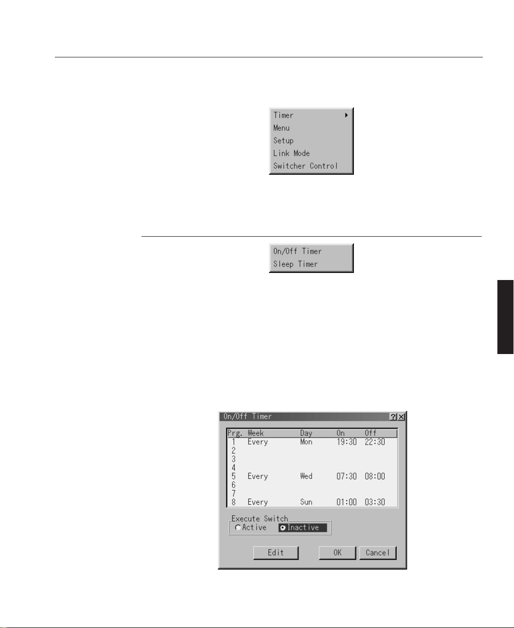
The Projector Options menu enables you to set preferences and other operating
options.
Timer
This feature enables you to turn on or off your projector automatically at a specified
time. There are two timer functions are available: On/Off Timer and Sleep Timer.
ON/OFF TIMER
The On/Off Timer enables you to schedule up to eight on and off times in 12 or 24
hour format. Before setting the On/Off Timer the current date and time must be
defined using the Date, Time Pre-set feature. When the On/Off Timer has been set it
is still possible to turn the projector on or off with the remote control.
C—33
System Operation
Projector Options
OPERATION
LBV00072; Revision A - 25/09/2001
Page 80

To schedule an On and Off Time:
1. Open the On/OFF Timer window.
2. Select EDIT and press ENTER on the remote control to open the EDIT window.
3. Set the Week, Day, On-Time and Off-Time using the CURSOR buttons and
INPUT buttons (1 through 10). To cancel the on-time or off time, use Delete.
4. Select Set and press ENTER on the remote control to complete the setting. To
close, select Close.
5. To enable your setting, select Active on the Execute Switch.
6. Select OK and press ENTER on the remote control to complete the setting.
When On Timer is set and the projector is in the standby mode, the "00" display
on the INDICATOR flashes to show that On Timer program is active.
The projector must be in stand-by mode at the time of turning on. The preset poweron time will be void if the cooling fan is working or an error occurs.
C—34
System Operation
OPERATION
LBV00072; Revision A - 25/09/2001
✍
Page 81

SLEEP TIMER
The Sleep Timer allows you to set the projector to automatically turn itself off after
a predefined time period.
To activate the Sleep Timer:
1. Select your desired time between 30 minutes and 2 hours in 30 minutes.
2. Select Set and press the ENTER button on the remote control.
3. The remaining time starts counting down.
4. The projector will turn off after the countdown is complete.
Menu
The Menu window allows you to set preferences for the on-screen menu system.
C—35
System Operation
OPERATION
LBV00072; Revision A - 25/09/2001
Page 82

Language - Up to seven languages are available for the on screen instructions. The
options are: English, German, French, Italian, Spanish, Swedish and Japanese.
Menu Display Time - The on screen menu display appears when the buttons on the
remote control, or the controls on the rear panel are pressed. The display can be set
to automatically turn off at a pre-selected time between 3 and 30 seconds after the
last menu action or set to manual operation. When set to manual, the display will be
turned on and off whenever the MUTE OSD button is pressed. If no button
operation is made for 20 minutes or more, the on-screen message will automatically
turn off.
Display Select - defines the status information displayed on the screen each time
you switch between input sources.
Date Format - defines the format of the date displayed in the upper left corner of
the screen.
Date, Time Preset - The projector has a built-in clock allowing the current year,
month, date and time to be displayed in the top of the screen. The clock will keep
working for about 3 days after the main power is turned off. If the main power is off
for 3 days or more, the built-in clock will be reset and the date and time will have to
be re-defined. The built-in clock will not reset while in the standby condition.
To set the Date and Time:
1. Select Date, Time Preset from the Menu window. The Date, Time Preset
window will open.
C—36
System Operation
OPERATION
LBV00072; Revision A - 25/09/2001
Page 83

C—37
System Operation
OPERATION
LBV00072; Revision A - 25/09/2001
2. Type in the current month, date and year using the input buttons on the remote
control. The month and date must be entered in two digit format.
3. Enter the current time in 24-hour format.
4. Select OK and press ENTER. The clock will start when the window closes.
Setup
There are five Setup windows used to define the operating options for the projector.
SETUP PAGE 1
Orientation - The projector can be set for floor projection, rear ceiling projection,
rear floor projection and front ceiling projection.
Background - The projector can be set to display a black, blue screen or logo when
no input signal is present.
S-Video Mode Select - Defines the S-Video signal detection mode to allow the
identification of S-Video signals with different aspect ratios. When set to S1, zoom
signals (16:9) will be identified. When set to S2, zoom signals and wide zoom
signals (4:3) will be identified.
Page 84

SETUP PAGE 2
Signal Select
RGB 1/2 - Allows the RGB1 and RGB2 inputs to be defined as either RGB,
Component or Auto. When set to Auto the projector attempts to automatically
detect the signal type. However, certain component signals may not be detectable.
Sync Termination - Defines the impedance of the sync signal for the RGB1 and
RGB2 inputs. The default setting for normal use is 75Ω. Hi-Z should be selected
when using a TTL signal.
SETUP PAGE 3
C—38
System Operation
OPERATION
LBV00072; Revision A - 25/09/2001
Page 85

Video 1/2 - Allows the manual selection of composite video standards for the Video
1 and Video 2 inputs.
S-Video 1/2 - Allows the manual selection of composite video standards for the
S-Video 1 and S-Video 2 inputs.
SETUP PAGE 4
Power Management - This feature automatically turns the projector off if there is
no RGB input for over five minutes. Power Management is not active for video
signals.
Power Off Confirmation - Determines whether a confirmation dialogue is
displayed when turning the projector off.
Keystone Save - Enables the current keystone settings to be saved. The keystone
setting is global and affects all sources. It is saved when the projector is switched
off.
Doubler (Video/S-Video only) - Sets the double speed interpolation of the video
signal
On = Non-Interlaced display
Off = Interlaced display
C—39
System Operation
OPERATION
LBV00072; Revision A - 25/09/2001
Page 86

Lens Memory - Applies the stored lens shift, focus and zoom adjustment values to
the selected signal.
On - Enables the lens memory function and applies saved settings to the selected
signal
Off - Disables the lens memory function so there will be no application of stored
lens settings.
Values for lens shift, focus and zoom can be stored regardless of whether or not
the lens memory function is enabled.
Lens Memory feature is not available in Link Mode.
User Name - An 18 character user name may be assigned to the projector using the
alpha-numeric INPUT keys on the remote control. The cursor keys allow movement
through the character entry field. To save the name, press the ENTER button.
SETUP PAGE 5
Communication Speed - Defines the baud rate of the PC CONTROL connector.
Select the appropriate rate between 4800 and 38400 according to the equipment
connected. The default rate is 38400bps.
C—40
System Operation
OPERATION
LBV00072; Revision A - 25/09/2001
✍
✍
Page 87

Projector ID - Each projector requires a unique address when used in serial
communication mode. Up to 64 addresses are available by selecting Enable and
then using the spin buttons to change the ID number. To save the setting, select OK.
Default Source Select - The projector can be configured to display either the last
input used or a preset input whenever it is turned on.
Link Mode
This feature is used for multiple projector connection using RGB
Digital Input/Output connectors.
The master projector is set to Master.
The other slave projectors are set to Slave.
When not using Link mode, set to Standalone.
See page D-4 for setting up for double or stacking in link mode.
Switcher Control
This feature sets the projector for communication with the ISS-6020 Switcher manufactured by NEC.
Standalone - Use the projector in stand alone operation
SW1 Level - Use the projector with one switcher
SW2 Level - Use the projector with two or more switchers
Selections SW1 and SW2 are not available in Link Mode.
C—41
System Operation
OPERATION
LBV00072; Revision A - 25/09/2001
✍
Page 88

When changing this setting, a confirmation box will appear.
If you want to restart your projector, select Yes, if not select No.
This setting only becomes effective following a restart of the projector.
Displays a list of all the files stored in the PC Card so that you can select a file you
want to display.
You can also sort files by file name or date, or display the file.
Although the list displays all the files in the PC Card, files can only be displayed in
text, HTML, JPEG or BMP format. To display the selected file, select Execute.
The Help menu provids three option - Contents, Source Information and Projector
information.
C—42
System Operation
P C Card Files
OPERATION
LBV00072; Revision A - 25/09/2001
✍
Help
Page 89

CONTENTS
The Contents option provides a list of functions for which online help is available.
Underlined functions provide a direct link to the corresponding item by selecting
the option and pressing Enter.
SOURCE INFORMATION
Source information consists of three pages displaying the configuration of the
current input signal.
C—43
System Operation
OPERATION
LBV00072; Revision A - 25/09/2001
Page 90

PROJECTOR INFORMATION
Displays information about the projector such as lamp usage, serial number, version
number etc. Projector Information provides four pages of information with page
four giving Link Mode details.
Page four of Projector Status displays the status of the master projector and linked
slave projectors. If more than three slave projectors are connected, the page buttons
can be used to display information on up to 16 slave projectors.
C—44
System Operation
OPERATION
LBV00072; Revision A - 25/09/2001
Page 91

Master ID - Displays the ID of the master projector.
Master Status - Shows the status of the master projector.
Connected PJ - Shows the number of slave projectors connected.
Slave Number - Displays the serial number of a slave projector.
Slave ID - Displays the ID of a slave projector.
Slave Status - Displays the status of a slave projector.
Running - The projector is operating.
Cooling Lamp - The fan is cooling the lamp.
Standby - The projector is in Standby mode.
Communication Error - A communication error has occured.
Connecting... - The projector is verifying the connection.
Error Standby - An error has caused the projector to enter Standby mode.
Page Buttons - Turns ‘pages’ to display information on additional slave projectors.
Reconnect - Confirms connection of all linked projectors.
Five internal Test Patterns are provided to assist with projector setup and alignment.
Use the Red, Green and Blue check boxes to turn individual colours on and off.
C—45
System Operation
Test Pattern
OPERATION
LBV00072; Revision A - 25/09/2001
Page 92

Cross Hatch - Used during manufacture to align the DMDs this pattern can be useful in the field for overlaying the images in multiple projector stacks.
Grey Bars - Provides a grey scale for adjusting the projector colour balance away
from that set during manufacture for applications where a custom balance is
required.
Black Raster - Used as the off measurement for calculating the on/off contrast
ratio.
Grey Raster - Gives an indication of the on screen luminance level that can be
expected when displaying video.
White Raster - Used for measuring projector luminance and for on reading for
on/off contrast ratio measurement.
System Operation
OPERATION
LBV00072; Revision A - 25/09/2001
Page 93

Screen Illuminance .......................................................... D— 1
DMD™ Operation and Usage .......................................... D— 2
Multiple Projection ........................................................... D— 4
Connection Instructions .............................................. D—4
Setting up for Double or Triple Stacking ..................... D—6
External Hardwired Control via Remote 1 Connector .. D—11
Projector Dimensions ..................................................... D— 1 2
Technical Specification ................................................. D—13
Advanced User Information
Section D: Advanced User Information
ADVANCED
LBV00072; Revision A - 25/09/2001
Page 94

Advanced User Information
ADVANCED
LBV00072; Revision A - 25/09/2001
Page 95

The projector's arc lamp emits a luminous flux measured in lumens. This flux is
directed at the screen and illuminates it, the illuminance (E) can be measured in Lux
(lumens/m2) or Foot Candles (lumens/ft2). The illuminance of the screen is
calculated by dividing the incident flux by the illuminated screen area.
The brightness of the screen, known as the screen luminance (B) is determined by
the amount of light reflected from it (or transmitted through it if using a rear
projection screen). If the screen is diffuse, the incident light is reflected into a
hemisphere. If the screen has a reflectivity (R), the screen luminance in candela/m
2
is given by (R x E) / π, where E is measured in Lux. If E is measured in FootCandles, the screen luminance is in Foot-Lamberts, and is given by R x E.
Examples:
1) A 6' x 4' 6" diffuse screen, with a reflectivity of 0.8 is illuminated by a projector
emitting 3000 lumens.
The screen illuminance (E) = F / A = 3000 / 27 = 111 Foot-Candles
The screen luminance (B) = R x E = 0.8 x 111 = 89 Foot Lamberts
2) A 4m x 3m screen with a reflectivity of 0.85 is illuminated by a projector
emitting 3500 lumens.
The screen illuminance (E) = F / A = 3500 / 12 = 292 Lux
The screen luminance (B) = (R x E) / π = (0.85 x 292) / π = 79 Candela/m
2
D—1
Advanced User Information
Screen Illuminance
ADVANCED
LBV00072; Revision A - 25/09/2001
Page 96

A DMD™ (Digital Micromirror Device™) is a true digital light modulator and
utilises 786,432 (gv) or 1,310,720 (sx) moving aluminium mirrors, with each one
representing a pixel in the final projected image. Each mirror is suspended over
address electrodes by a torsion hinge between two posts. Depending on the voltage
polarity applied, each mirror will either tilt to left or to the right. When light is
applied to the complete DMD™, only the light redirected from a mirror tilting to
the left is projected.
The projector optically filters white light from the lamp into its constituent red,
green and blue. Each colour illuminates a separate DMD™ whose modulated output
is then recombined with the other two to form the projected full colour image.
DMD & Digital Micromirror Device are trademarks of Texas Instruments Incorporated.
D—2
Advanced User Information
DMD™ Operation and Usage
ADVANCED
LBV00072; Revision A - 25/09/2001
Projection Lens
Illumination
(Lamp)
Offset Address Electrode
Support Posts
Torsion Hinge
Flat
Left Tilt
Right Tilt
Left
Tilt
Right
Tilt
Mirror Element
Light
Dump
Projector
Lamp
RGB RGB RGB
Full Colour Image
Displayed on Screen
Projector
Lens
Optical Filtering of White Light
into Red, Green and Blue Light
White Light
Green
Light
Red
Light
Blue
Light
White Light
DMDs™
Page 97

The mirrors in the DMD™ are arranged in a 1024 x 768 (gv) or 1280 x 1024 (sx)
array allowing images of all aspect ratios to be displayed. However, the proportion
of DMD™ effectively used will differ depending on the aspect ratio of the image
e.g. a 5 x 4 aspect ratio on a 5100gv would only require the use of 960 x 768 mirrors. The diagrams below show the DMD™ usage for each aspect ratio (4 x 3, 5 x 4,
8 x 5, 14 x 9 and 16 x 9) with the shaded areas representing redundant mirrors.
D—3
Advanced User Information
ADVANCED
LBV00072; Revision A - 25/09/2001
sx=1280 x 1024 Mirrors
DMD™ Size
gv=1024 x 768 Mirrors
5 x 4 Aspect Ratio
gv = 960 x 768 Mirrors used
sx = 1280 x 1024 Mirrors used
14 x 9 Aspect Ratio
gv = 1024 x 658 Mirrors used
sx = 1280 x 823 Mirrors used
4 x 3 Aspect Ratio
gv=1024 x 768 Mirrors used
sx = 1280 x 960 Mirrors used
8 x 5 Aspect Ratio
gv = 1024 x 640 Mirrors used
sx = 1280 x 800 Mirrors used
16 x 9 Aspect Ratio
gv = 1024 x 576 Mirrors used
sx = 1280 x 720 Mirrors used
Page 98

Up to three HIGHlite Displays projectors can be stacked without any additional
framing (gravity stacking). One unit can be stacked on top of the other up to three
units. Make sure that each foot is securely seated on the stacking pad.
Connection Instructions
To connect multiple projectors use the supplied DVI-D cable to connect the RGB
DIGITAL output (INPUT 9) of the master projector to the RGB DIGITAL input of
the slave projector (the second and third stack) until all the projectors are connected.
D—4
Advanced User Information
Multiple Projection
ADVANCED
LBV00072; Revision A - 25/09/2001
Page 99

Next, using a commercially available, bi-directional RS-232C cable connect the
OPTION OUT terminal of the master projector to the OPTION IN terminal of the
slave projector(s) until all the projectors are connected.
OPTICAL AND MECHANICAL ADJUSTMENT
Place the projectors at the proper height for best screen to projector relationship and
ensure that all projectors have the same display orientation. Next, turn on all the
projectors and display the internal crosshatch test pattern using a different single
colour for each projector e.g. turn on green for the master projector, red for the first
slave projector and blue of the other second slave projector.
D—5
Advanced User Information
ADVANCED
LBV00072; Revision A - 25/09/2001
OUTPUT
RGB
DIGITAL
INPUT9
OUTPUT
RGB
DIGITAL
INPUT9 OUTPUT
RGB
DIGITAL
INPUT9
OPTION
IN
OUT
OPTION
IN
OUT
OPTION
IN
OUT
Master Slave Slave
DVI-D Cable (1 supplied)
Bi Directional RS232C Cable
(not supplied)
Page 100

Setting up for Double or Triple Stacking
Adjust the lens shift, zoom and focus to clearly display all projected patterns.
If the vertical alignment of the projector(s) is incorrect, adjust the height of the
feet. If there is any keystone distortion, use Keystone adjustment to correct and
save the settings on each projector.
SIGNAL DATA PREPARATION
When stacking multiple projectors each projector should be configured to display
the input image in exactly the same manner. This requires configuring the master
projector for each input signal type, adjusting the image and copying it to the slave
projectors using a PC card as follows:
1. Choose one projector to be the master projector and turn it on.
2. Display all the desired input signals adjusting each signal to provide an optimum
image and place the master projector in standby mode.
3. Remove the PC Card slot decorative panel and insert a PC card into the slot.
4. Press and hold CANCEL, then press POWER on the rear panel of the master
projector. The POWER indicator will change to steady green and the PC Card
Access indicator will start flashing. The data will be automatically stored on the
PC card and the POWER indicator will change to amber.
5. Remove the PC card from the slot of the master projector. With the slave
projector in standby, insert the PC card into the slot of a slave projector.
Since data in the slave projectors will be lost at this time, make backup copies of
them before proceeding.
6. Press and hold ENTER, then press MENU on the rear panel of the slave
projector. The POWER indicator will change to steady green and the PC Card
D—6
Advanced User Information
ADVANCED
LBV00072; Revision A - 25/09/2001
✍
✍
 Loading...