

Page 1

EVOLUTION LX
INK JET PRINTERS
INSTALLATION AND OPERATION MANUAL
digital design inc.
67 Sand Park Road
Cedar Grove, NJ 07009
(973) 857-9500
http://www.evolutioninkjet.com/
This manual is for use in operating and maintaining the EVOLUTION LX 1 (LX 1)
and EVOLUTION LX 2 (LX 2) Ink Jet Printer. This manual includes various optional
features, which may not be included in your basic model printer.
For basic start-up instructions, please refer to PART 1 Installation Procedures.
All rights reserved. No part of this document may be reproduced, stored on a
retrieval system, or transmitted in any form, or by any means electronic,
mechanical, photocopying, recording or otherwise, without the prior permission of
Digital Design Inc.
Digital Design Inc. has a policy of continual product improvement. The Company
therefore reserves the right to modify the information contained in this manual
without prior notice.
ALL PRINT CARTRIDGES SUPPLIED BY DIGITAL DESIGN INC. ARE
FACTORY TESTED AND PROFILED TO PRODUCE AN OPTIMUM AND
CONSISTANT CODE. USING OTHER THAN AUTHORIZED CARTRIDGES
WILL CAUSE UNDESIRABLE RESULTS.
EACH FLASH DATA CARD IS PROFILED EXPLICITELY FOR ITS’ INTENDED
PRINTER, AND IS SECURITY LOCKED PROHIBITING USE IN OTHER THAN
THE ORIGINAL PRINTER FOR WHICH IT WAS PURCHASED. KEEP ALL
UPGRADE CARDS IN A SECURE PLACE.
EVOLUTION LX 1 IS A BASIC MODEL WITH NO VARIABLE FIELD
PROGRAMMING CAPABILITIES. OPTIONAL SOFTWARE MAY BE ADDED
TO A BASIC UNIT AND IS COVERED IN THIS MANUAL.
EVOLUTION LX 2 IS A FULL FEATURED MODEL WITH THE CAPABILITY OF
ADDING OPTIONAL BARCODES OTHER THAN THE STANDARD 8
INCLUDED SYMBOLOGIES.
1 EVOLUTION LX SYSTEM MANUAL Issue 1.0 5 DEC 2009
Page 2

INSTALLATION AND OPERATION MANUAL ................................. 1
PART 1: INSTALLATION PROCEDURES....................................... 1
INSTALLING THE EVOLUTION LX PRINTING SYSTEM............................................................... 1
MOUNTING ON PRODUCTION LINE ..................................................................................... 1
EVOLUTION LX MOUNTING OPTIONS ................................................................................. 2
GROUNDING STRAP INSTALLATION ................................................................................... 4
INPUT POWER CONNECTION............................................................................................... 4
INSTALLING THE PRINT CARTRIDGE...................................................................................... 5
CONNECTING THE CONTROLLER TO THE PRINTER............................................................ 6
VERIFYING THE PRINTER SOFTWARE VERSION.................................................................. 6
VERIFYING THE PRINTER SOFTWARE VERSION.................................................................. 7
SYSTEM RESET ......................................................................................................................... 8
MULTIPLE PRINT HEADS .......................................................................................................... 9
EVOLUTION LX QUICK START...................................................................................................... 9
EVOLUTION LX QUICK START.................................................................................................... 10
CHANGING LANGUAGE PROMPTS .................................................................................... 10
ENABLING PRINTING MODE ............................................................................................... 10
HEAD SELECT MODE........................................................................................................... 10
ENTERING A MESSAGE....................................................................................................... 11
STORING A MESSAGE (LX 1 WITH OP 1, 1.5, 2, 3 OR LX 2) ............................................ 12
LOADING A MESSAGE (LX 1 WITH OP 1, 1.5, 2, 3 OR LX 2)............................................. 13
EVOLUTION LX QUICK SETUP.................................................................................................... 14
PART 2: OPERATION PROCEDURES............................................. 1
OVERVIEW.................................................................................................................................. 1
CONTROLLER AND LCD........................................................................................................ 1
KEYPAD KEY DESCRIPTIONS............................................................................................... 2
TURNING ON THE PRINT STATION FOR THE FIRST TIME................................................ 3
CHECKING SYSTEM INFORMATION .................................................................................... 3
CHECKING LOADED FONTS ................................................................................................. 3
CHANGING SYSTEM DATE AND DAY OF WEEK CODES................................................... 4
CHANGING SYSTEM TIME AND DATE ROLL OVER TIME.................................................. 5
LCD BACKLIGHT AND CONTRAST CONTROL..................................................................... 6
SETTING PRINTING PARAMETERS ......................................................................................... 7
DEFINITIONS........................................................................................................................... 7
PRINTING AND STOPPED MODE ......................................................................................... 7
F1 MENU.................................................................................................................................. 9
F2 MENU................................................................................................................................ 12
F3 MENU................................................................................................................................ 14
F4 MENU................................................................................................................................ 19
SETTING PRINT DELAY AND LINE SPEED............................................................................ 24
SETTING LINE SPEED.......................................................................................................... 24
SETTING PRINT DELAY ....................................................................................................... 25
INPUT, EDIT OR DELETE MESSAGES ................................................................................... 26
SEQUENCE NUMBER LOT COUNTER SETUP AND SELECTION .................................... 29
VARIABLE FIELD FORMAT PRINTING (LX1 WITH OP 2, 3 OR LX 2)................................ 34
PASSWORD PROTECTION (LX1 WITH OP 1,2,3 or LX 2).................................................. 36
MIXED RASTER MESSAGE ENTRY .................................................................................... 37
ENTERING A MIXED RASTER PREFIX ............................................................................... 38
MESSAGE STORAGE (LX1 WITH OP 1, 1.5,2,3 OR LX 2) ..................................................... 40
STORING A MESSAGE......................................................................................................... 40
RECALLING A STORED MESSAGE..................................................................................... 40
PART 3: MAINTENANCE PROCEDURES....................................... 1
PERIODS OF SHUT DOWN........................................................................................................ 1
2 EVOLUTION LX SYSTEM MANUAL Issue 1.0 5 DEC 2009
Page 3

SHORT PERIODS OF SHUT DOWN ...................................................................................... 1
LONG PERIODS OF SHUT-DOWN ........................................................................................ 2
PRINT CARTRIDGE MAINTENANCE......................................................................................... 3
CLEANING TRAY 4x50-CLEAN (Ordered Separately) ........................................................... 4
PRINTER MAINTENANCE.......................................................................................................... 5
EXPLODED VIEW OF THE PRINT HEAD CHASSIS.............................................................. 5
PRINTER ADDED FEATURES ................................................................................................... 6
PART 4: TROUBLESHOOTING AND REPAIRS ............................. 1
PART 5: PARTS LIST AND OPTIONS............................................. 1
PART 6: COMMUNICATIONS PROTOCOL .................................... 1
DESCRIPTION............................................................................................................................. 6
DATA WORD DEFINITION...................................................................................................... 6
BAUD RATE............................................................................................................................. 6
DEFINITIONS........................................................................................................................... 6
CABLING FOR EVLINK ENVIRONMENT ............................................................................... 7
HARDWARE INTERFACE....................................................................................................... 7
PHYSICAL CONNECTIONS RS485 PRINTER....................................................................... 7
PROTOCOL FORMAT:............................................................................................................ 7
EVOLUTION PRINTABLE CHARACTER SET ............................................................................ 8
SOFTWARE PROTOCOL ........................................................................................................... 9
ERROR CODES ........................................................................................................................ 10
COMMANDS:............................................................................................................................. 11
EXAMPLE WRITTEN IN C ........................................................................................................ 26
EXAMPLE WRITTEN IN VB ...................................................................................................... 28
EXAMPLE USING HYPER TERMINAL..................................................................................... 30
EXAMPLE USING EVCOMMTEST ........................................................................................... 32
PART 7: OPTION JUMPERS AND CABLING .................................. 1
OPTION JUMPER DESCRIPTIONS ........................................................................................... 1
VSEL J7.................................................................................................................................... 1
PDEN J8................................................................................................................................... 1
ENSEL J9................................................................................................................................. 1
PRSEL J10............................................................................................................................... 1
JUMPER LOCATION ............................................................................................................... 2
OPTION CABLING DESCRIPTIONS .......................................................................................... 3
PART 8: SPECIFICATIONS .............................................................. 1
PRINTER SPECIFICATIONS ...................................................................................................... 1
PRINT CHARACTERISTICS.................................................................................................... 1
CONTROLLER......................................................................................................................... 1
PRINTER.................................................................................................................................. 1
ENVIRONMENTAL CONDITIONS........................................................................................... 1
GENERAL ................................................................................................................................ 1
DEFAULT SETTINGS.................................................................................................................. 2
APPENDIX A–PRODUCING RELIABLE BARCODES... 1
BARCODE INTEGRITY ............................................................................................................... 1
CONTRAST RATIO ..................................................................................................................... 1
BAR SEPARATION ..................................................................................................................... 1
QUIET ZONE ............................................................................................................................... 1
PROGRAMMING BARCODES.................................................................................................... 2
BARCODE TECHNIQUES........................................................................................................... 3
BARCODE TYPES ...................................................................................................................... 7
USING CHECK CHARACTER................................................................................................... 11
3 EVOLUTION LX SYSTEM MANUAL Issue 1.0 5 DEC 2009
Page 4

INSTALLATION AND OPERATION MANUAL
PART 1: INSTALLATION PROCEDURES
INSTALLING THE EVOLUTION LX PRINTING SYSTEM
Caution should be taken while installing the EVOLUTION LX printing system on
your equipment. Digital Design Inc. has taken every precaution to ensure a safe
and accurate instruction set to guide the installer through the installation process.
Follow the operational guidelines in the installation procedures.
Various OPTION PACKAGES (OP) are available and are referenced throughout
this manual.
VERIFY THAT YOUR EQUIPMENT IS IN PROPER OPERATING
CONDITION.
LOCATE A CONVENIENT POSITION ON YOUR EQUIPMENT.
EVOLUTION LX REQUIRES 4-1/2" OF SPACE ON THE
PRODUCTION LINE.
FOLLOW THE INSTALLATION PROCEDURES.
READ CAREFULLY ALL INSTALLATION PROCEDURES BEFORE
PROCEEDING.
INSTALL THE PRINTING SYSTEM ON YOUR EQUIPMENT.
THERE IS NO EXTRA HARDWARE REQUIRED OTHER THAN
THAT SUPPLIED IN THE INSTALLATION KIT.
MOUNTING ON PRODUCTION LINE
Locate the supplied mounting template
and affix in a convenient location on the
production line. Spot and drill both
mounting holes for a 5/16” bolt. NOTE:
the user may also thread the side of the
conveyor using a 5/16” tap.
Fasten the mounting bracket to the
conveyor using the supplied mounting
hardware and ensure that the supplied
ground strap is located securely beneath
either of the two mounting bolts, and that
conductivity to earth ground is less than 1 ohm. This ensures a proper path for
static discharge, should the need arise.
1 EVOLUTION LX SYSTEM MANUAL Issue 1.0 5 DEC 2009
Page 5
EVOLUTION LX MOUNTING OPTIONS
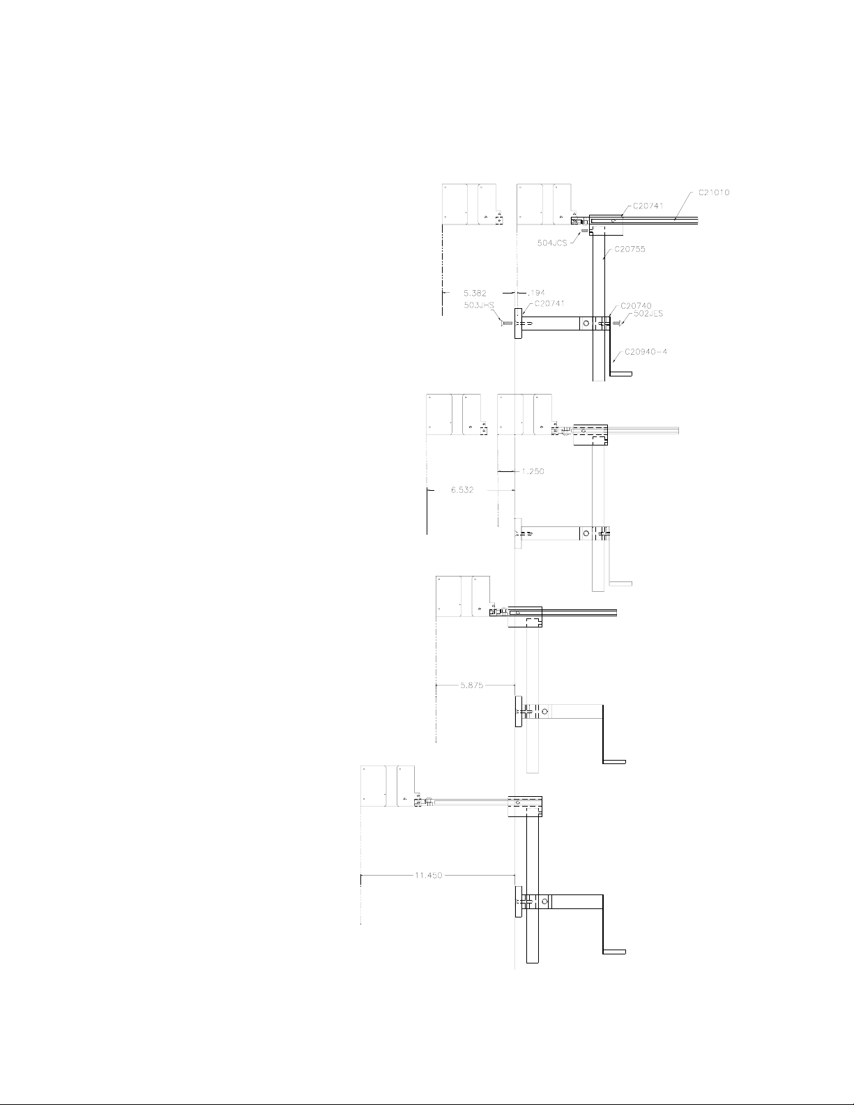
The EVOLUTION LX mounting bracket assembly C21010 has a number of
possible mounting configurations, which allows adaptability to a variety of
production equipment.
The top cross slide
bracket C20741 may be
rotated 180 deg by
loosening the included
setscrew 504JCS and
rotating the bracket. This
allows the print head to be
extended by just over 1”.
Although this is not a
significant amount it might
be helpful.
Refer to the first two
pictorials to identify the
various components of the
mounting bracket system
C21005.
Rotating the horizontal
mounting bracket C20740
may further increase
extension into the
production line. The
mounting centers for both
the base block C20741
and controller holder
C20940-4 are identical.
Remove the two 502JHS
flat head screws from the
base block and the two
502JES button head
screws, rotate the bracket
and replace both the base
block and controller
holder.
The above procedure
allows for a print head
displacement from .625”
before the production line
to 11.450” into the
production line.
2 EVOLUTION LX SYSTEM MANUAL Issue 1.0 5 DEC 2009
Page 6
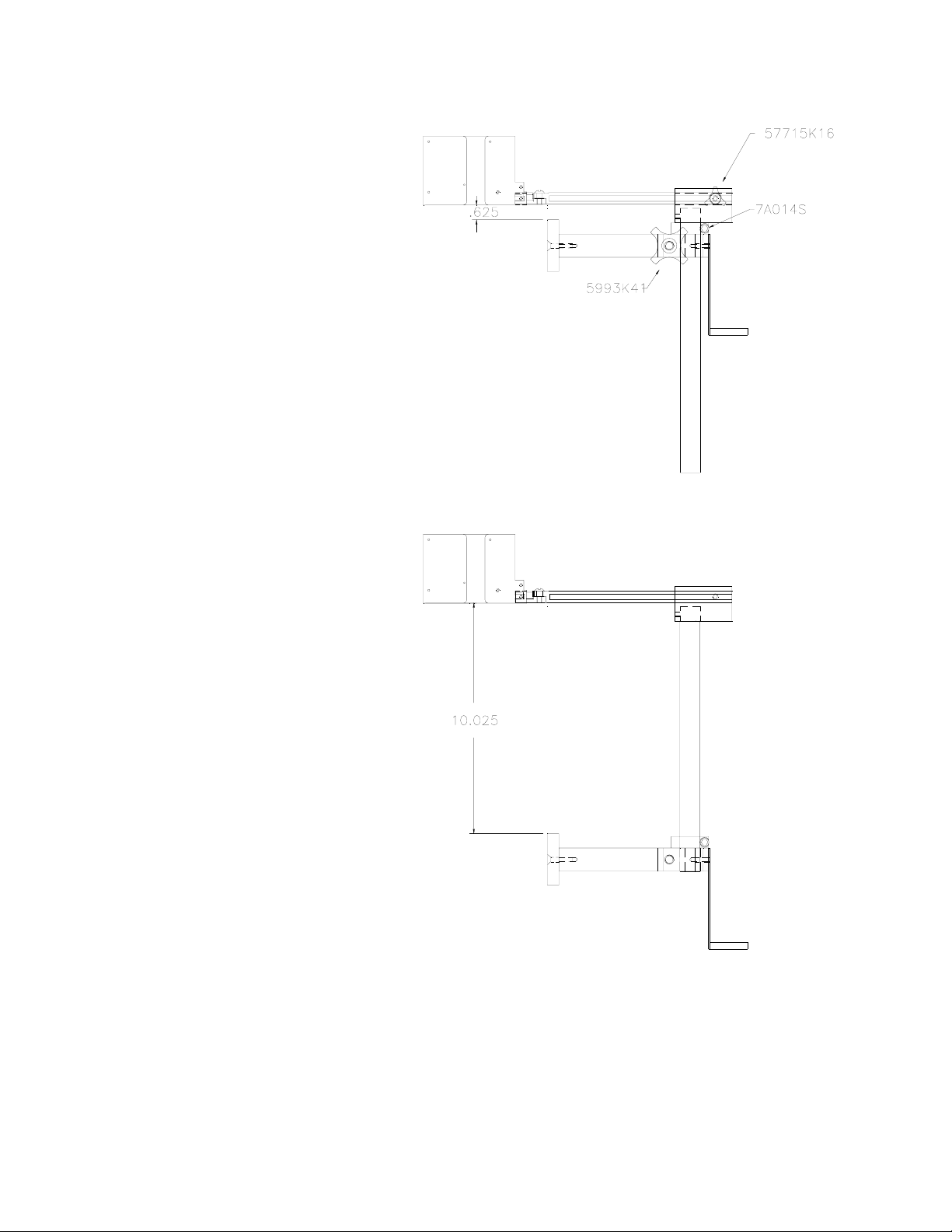
Vertical height adjustment
for the EVOLUTION LX
print head is accomplished
by loosening the included
hand knob 5993K41.
Note that the hand knob
may be mounted on either
side of the horizontal
mounting bracket
depending on the
orientation of the bracket.
It should also be noted
when rotating the cross
slide assembly it is
necessary to move the
smaller hand knob
57715K16 to the other
side of the bracket so it
aligns with the flat on the
horizontal extension rod.
After the mounting bracket
is configured loosen the
locking collar 7A014S and
re-locate it against the
horizontal extension
bracket and tighten. This
allows the user to loosen
the horizontal mounting
bracket-locking knob and
rotate the assembly
without losing the height
adjustment.
3 EVOLUTION LX SYSTEM MANUAL Issue 1.0 5 DEC 2009
Page 7
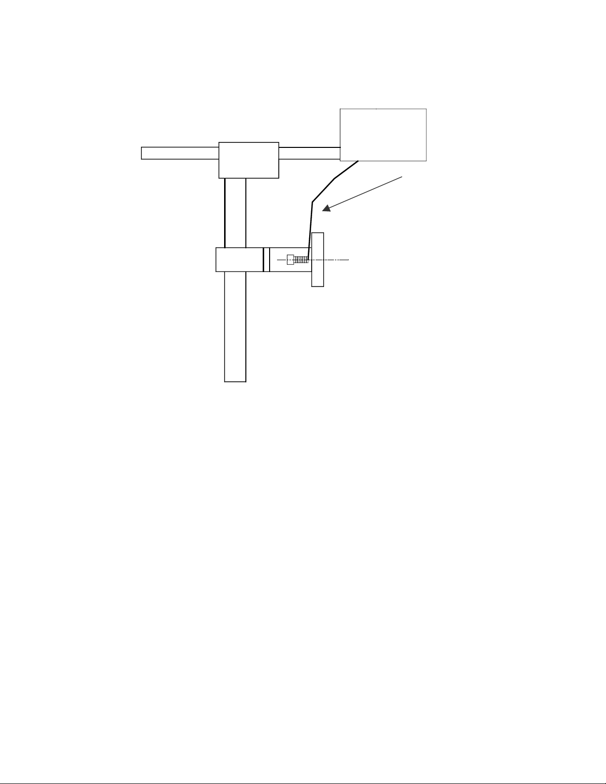
GROUNDING STRAP INSTALLATION
INSTALL STRAP UNDER
5/16” SCREW. ENSURE
CONDUCTIVITY TO
EARTH GROUND IS LESS
THAN 1 OHM
INPUT POWER CONNECTION
Insert the power plug to the available power source. The supplied power supply
is universal and will auto detect 100/240 VAC 50-60hZ.
No other adjustments are necessary.
4 EVOLUTION LX SYSTEM MANUAL Issue 1.0 5 DEC 2009
Page 8
INSTALLING THE PRINT CARTRIDGE
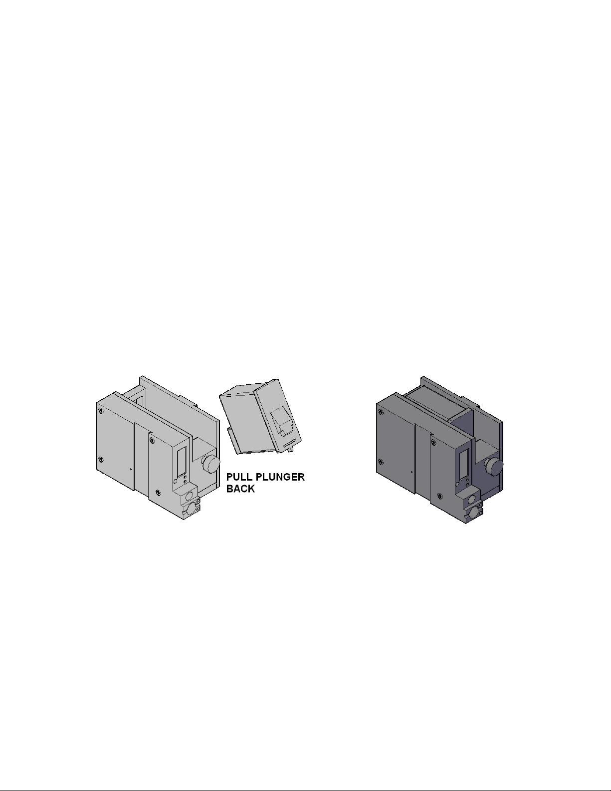
Remove the protective film from the face of the print head and DISCARD. This
protective film should not be re-applied. If it is necessary to remove the print
head and store for a long period of time, it is best to place the cartridge in a seal
able plastic bag.
Proper insertion of the cartridge is necessary to avoid damage to either the
cartridge or printer.
Pull back on the rear plunger, insert the cartridge at approximately a 30 deg
angle and press downward until the cartridge is in place, and then release the
plunger. A light snap will be felt as the locking mechanism presses the cartridge
into the correct position.
NOTE: EACH PRINT CARTRIDGE HAS BEEN PROFILED
AT THE FACTORY. THIS PROCEDURE DETERMINES
THE OPTIMAL OPERATING CHARACTERISTICS FOR
EACH INDIVIDUAL CARTRIDGE. USING ANY OTHER
PRINT CARTRIDGE WILL HAVE UNDESIRABLE
RESULTS.
NOTE: WHEN A NEW CARTRIDGE IS INSTALLED,
BOTH THE RED AND GREEN LIGHT WILL FLASH
TWICE INDICATING A CORRECT INSTALLATION.
THE APPROPRIATE CARTRIDGE SETTINGS AND
CORRECT INK LEVEL WILL AUTOMATICALLY BE
CONFIGURED.
5 EVOLUTION LX SYSTEM MANUAL Issue 1.0 5 DEC 2009
Page 9
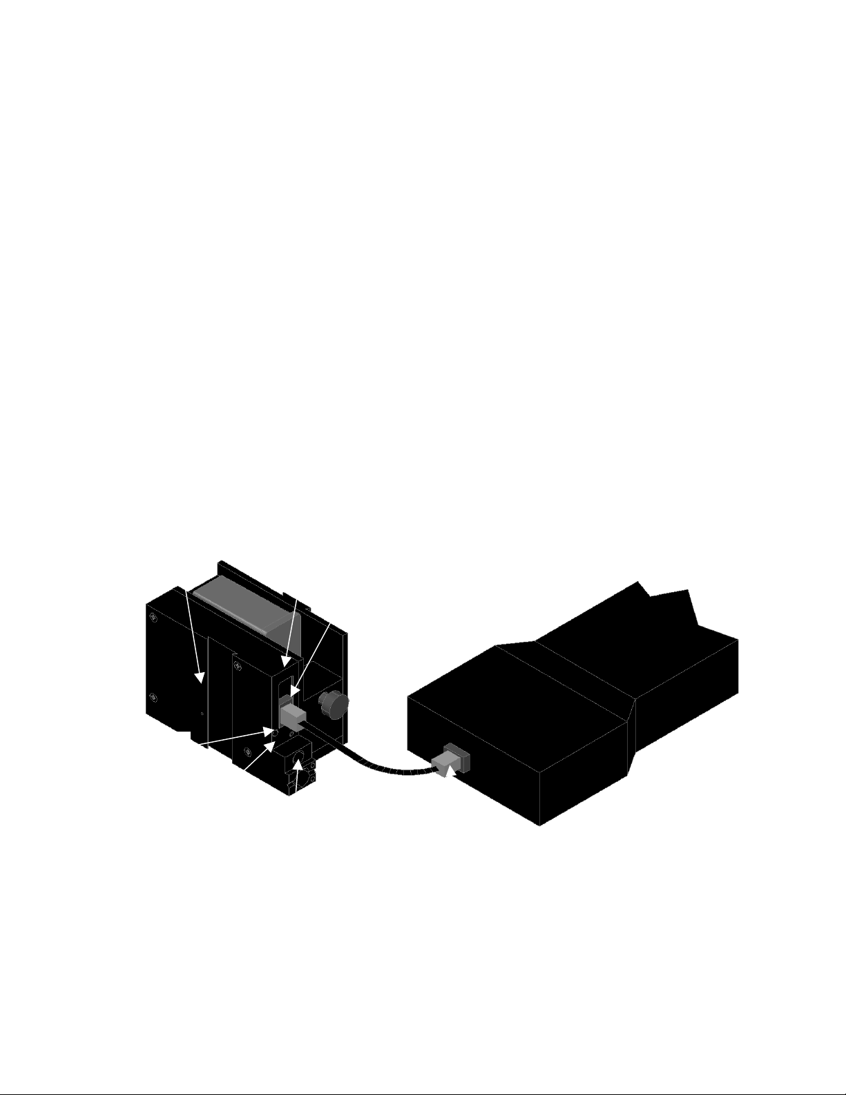
CONNECTING THE CONTROLLER TO THE PRINTER
Connect the Controller to the printer using the supplied 3 FT (.9 m) interconnect
cable C21008-3 supplied with the Printing System. The cable is a standard RJ50
(10 conductor). Longer cables are available as required.
Connect either end of the cable to the Printer Assembly and securely lock in
place. NOTE: THE CONNECTOR MUST BE PLUGGED INTO THE INPUT RJ50
CONNECTOR LOCATED ADJACENT TO THE LED’S AND MARKED WITH
AN ARROW POINTING TOWARDS THE CONNECTOR. A click will be felt when
the connector is in the appropriate position. Connect the free end to the
Controller Assembly and ensure the connector is securely seated.
CAUTION: NOTE ORIENTATION OF THE CONNECTORS. DO NOT FORCE
CONNECTORS INTO POSITION SECURELY LATCH (CLICK) INTO
POSITION.
CONTROLLER MUST PLUG INTO THE PRINTER RJ50 INPUT CONNECTOR
ODER INPUT.
THE POWER INPUT CONNECTOR MUST BE SECURELY INSERTED INTO
THE PRINTER. UPON PROPER INSERTION BOTH THE RED AND GREEN
LED’S WILL FLASH INDICATING PROPER CONNECTION.
RESET
SWITCH
ACCESS
HOLE
GREEN
CYCLE LED
RED PRINT
ENABLE LED
POWER INPUT
+12VDC @1.5A
PRINTER RJ50 OUTPUT
CONNECTOR
PRINTER RJ50 INPUT
CONNECTOR
CONTROLLER RJ50
CONNECTOR
6 EVOLUTION LX SYSTEM MANUAL Issue 1.0 5 DEC 2009
Page 10

VERIFYING THE PRINTER SOFTWARE VERSION
To verify the current operating software press the V key.
CONTROLLER 2.0
PRINTER 3.06A _ _ _ _
PRINTER SN XXXXXX
EXIT ANY KEY
The first line indicates the version of the controller software
The second line numeric indicates printer software version and the letter is the
firmware version of the printer. The ‘+’ (s) following indicate options installed:
The dashes shown in the pictorial above and in the explanation below the _ _ _ _
characters represent the space character and are not actually displayed.
+ _ _ _ = Option 1
_ +_ _ = Option 1.5
+ +_ _ = Option 1 and Option 1.5
+++ _ = Option 2
++++ = Option 3
NOTE: the EV 2 LX will display all (++++) signs as all features are enabled.
The third line indicates the serial number of the printer
7 EVOLUTION LX SYSTEM MANUAL Issue 1.0 5 DEC 2009
Page 11

SYSTEM RESET
Soft Reset
There are two types of resets available in the Evolution printing system. The first
type of reset is a SOFT RESET.
Remove the cable between the controller and print
ERASE STORED
MESSAGES
YES OR NO Y/N
RESET PRINT HEAD
YES OR NO Y/N
ALL HEADS
WILL BE RESET
CONTINUE = X KEY
ANY OTHER EXITS
station.
Pressing the R key while reconnecting the cable to
the controller will display the reset screen.
CAUTION: A response of Y will delete all stored
messages from the controller.
The next screen to appear prompts the user to
determine if a print head is to be restored to its
default value.
CAUTION: ALL PRINT HEADS CONNECTED
TO THE CONTROLLER WILL BE RESET TO
FACTORY DEFAULT CONDITIONS. THIS
INCLUDES RESETTING EACH UNIT ADDRESS
TO 1. TO PREVENT THIS REMOVE ALL
INTERCONNECTED PRINT HEADS EXCEPT
FOR THE UNIT TO BE RESET FROM THE
DATA LINK.
The specific unit address must be reset to the correct value after
a reset.
Hard Reset
The second reset is a hard reset. Disconnect the power cable. Insert a standard
paper clip into the hole on the female dovetail side of the cabinet, and while
holding the paper clip in place (a light click will be felt) re-apply the power
connector. Keep the reset switch depressed for at least 5 seconds.
This operation will reset the printer to the factory default settings and clear any
current message.
NOTE: FOR BOTH A SOFT AND HARD RESET THE DISPLAY
WILL SHOW THE DEFAULT MESSAGE: “EVOLUTION”
8 EVOLUTION LX SYSTEM MANUAL Issue 1.0 5 DEC 2009
Page 12
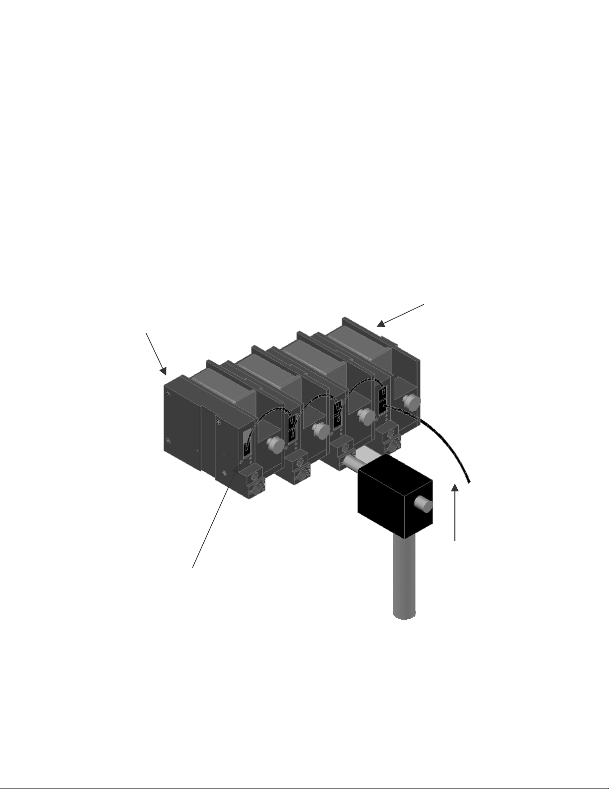
MULTIPLE PRINT HEADS
EVOLUTION LX printing systems have the ability to reside on a network. The
network may contain from 1 to 32 printers connected via RJ50 cables. These
cables are available in varying lengths depending on the application.
Each mounting bracket can support up to 4 printers and would typically
interconnect with a 7” RJ50 data cable.
NOTE: When connecting multiple print heads place no more than 4 stations
on a mounting bracket as shown.
NOTE: Please address each unit individually as per page 2-20 (SET UNIT
ID) prior to daisy chaining the printers. Special care must be taken to
connect the output of the first printer to the input of the next printer.
PRINTER
ADDRESS 4
PRINTER ADDRESS
1
PRINTER
LOCKING SET
SCREW
9 EVOLUTION LX SYSTEM MANUAL Issue 1.0 5 DEC 2009
TO
CONTROLLER
OR COMPUTER
DATA LINK
Page 13
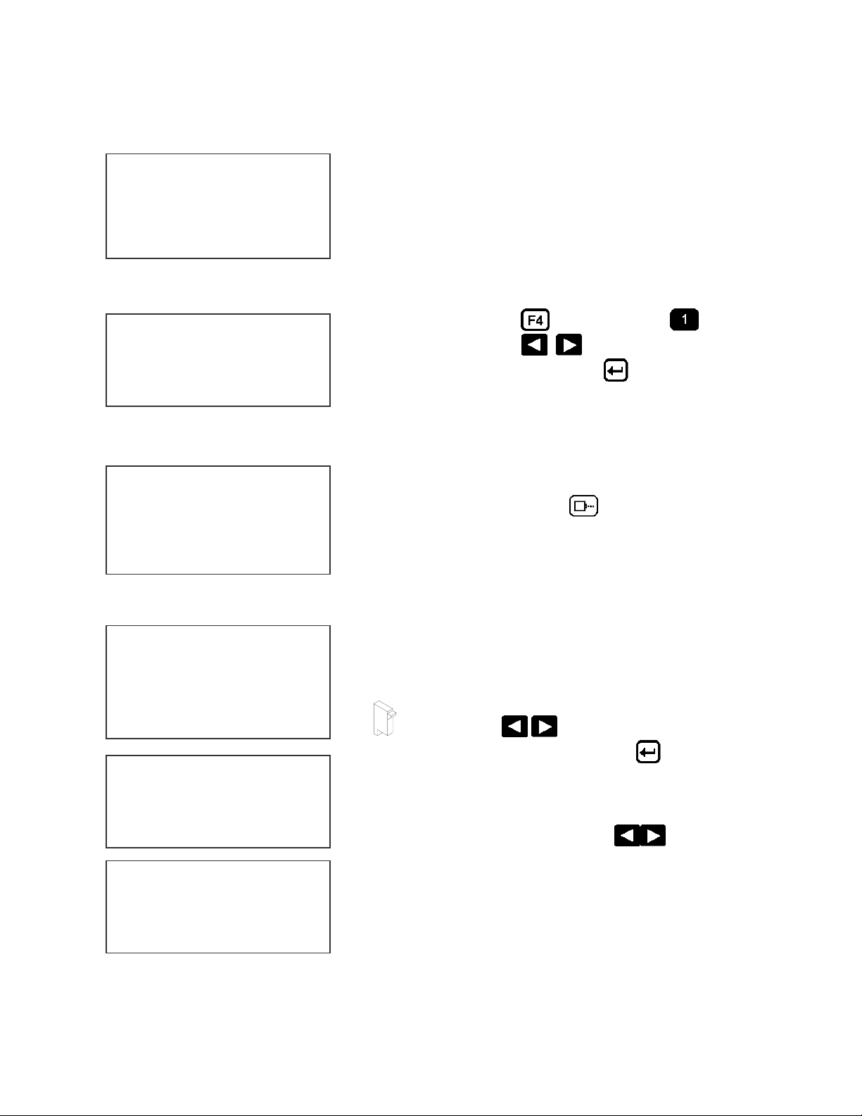
EVOLUTION LX QUICK START
O
U
Connect the printer to the appropriate power source.
LX x STOPPED
HD 1- - >SPEED=100
EV
CHANGING LANGUAGE PROMPTS
L
Connect the controller to the printer. The controller
derives power from the printer.
On startup the LCD will display as pictured.
WHERE THE LX x IS EITHER LX 1 OR LX 2
< - - SELECT - - >
ENGLISH
ENABLING PRINTING MODE
LX x PRINTING
HD 1- - >SPEED=100
EVOLU
HEAD SELECT MODE
LX x STOPPED
HD 1- - >SPEED=100
Press the F4 key and select for
LANGUAGE. Use the keys to select the
desired language and press the to select the
language.
Press the GREEN PRINT key to start printing
The hand held controller can program up to 32
printers on an RS485 data link. The factory default
sets each printer to ADDRESS 1. Selection of
another print head other than ADDRESS 1, press
EVOLU
the
key. Use the keys to select the
alternate printer number and press the key. The
< - - SELECT - - >
WHICH HEAD = 1
NO RESPONSE
ANY KEY TO EXIT
10 EVOLUTION LX SYSTEM MANUAL Issue 1.0 5 DEC 2009
printer whose address was selected will respond
with the current message and appropriate
parameters.
As an added convenience using the will auto
scan to find the next available head connected to
the network.
NOTE: If more than 1 printer has the same
address either a NO RESPONSE message or
erroneous results may be displayed.
Page 14
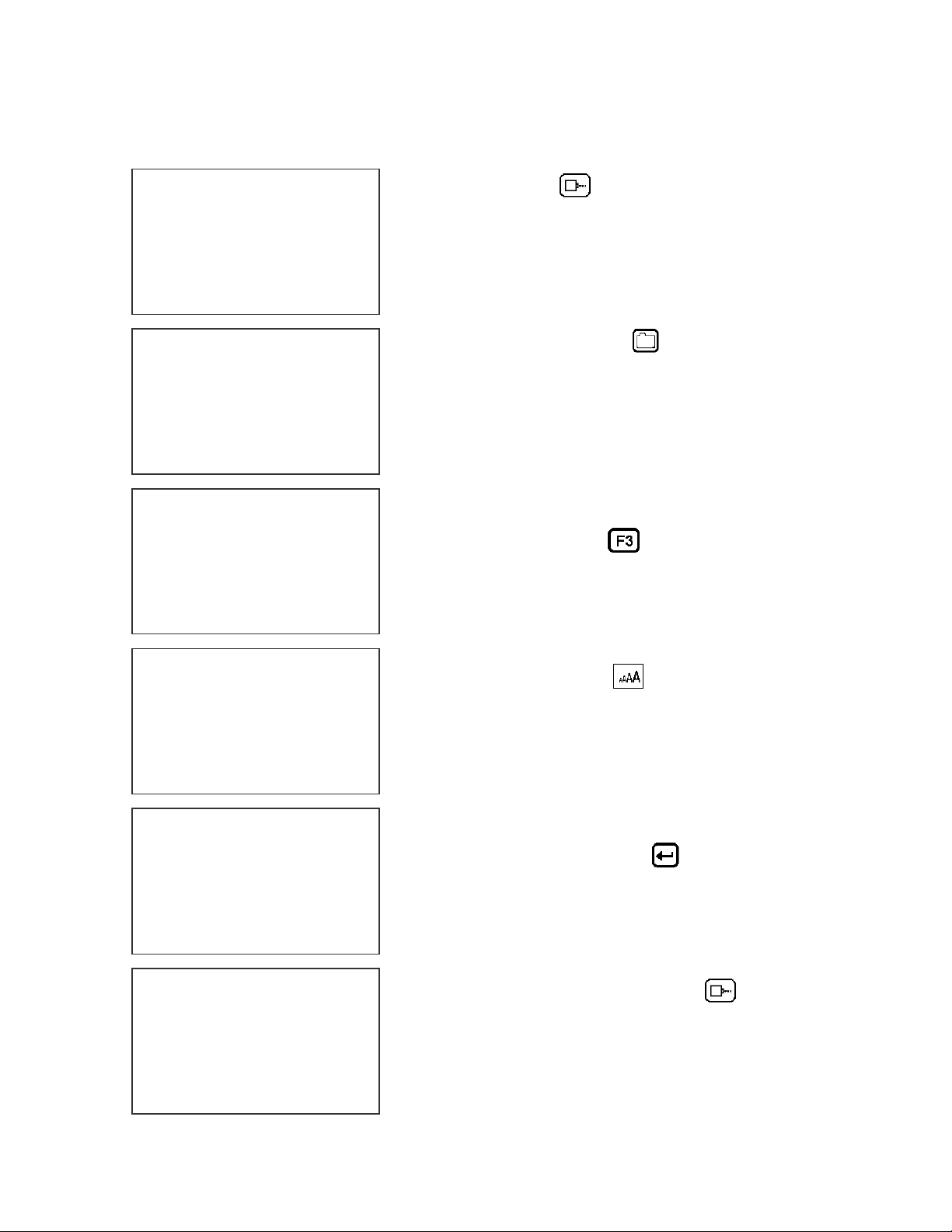
ENTERING A MESSAGE
If the printer is in the PRINTING mode press the
LX x STOPPED
HD 1- - >SPEED=100
EVOLU
MESSAGE ENTRY
- - - - FONT-1 LINE
EVOLU
MESSAGE ENTRY
- - - - FONT-1 LINE
MESSAGE ENTRY
- - - - FONT-1 LINE
EXP 12/
MESSAGE ENTRY
- - - - FONT-1 LINE
2/10/04
LX x PRINTING
HD 1- - >SPEED=100
GREEN PRINT key
The LCD display will change from PRINTING to
STOPPED.
Press the GREEN EDIT key
The LCD will display the MESSAGE ENTRY
mode.
Press the BLUE F3 key to delete the entire
message.
Press the BLUE FONT key to select the
desired font size and enter the text EXP 12/10/04.
Notice that as characters are typed the message
will automatically (if necessary) scroll to the left.
Pressing the ENTER key will end the
MESSAGE ENTRY mode, re-display the message
and enter the STOPPED Mode.
Press the GREEN print enable key to enter
the PRINTING Mode
EXP 12/
11 EVOLUTION LX SYSTEM MANUAL Issue 1.0 5 DEC 2009
Page 15
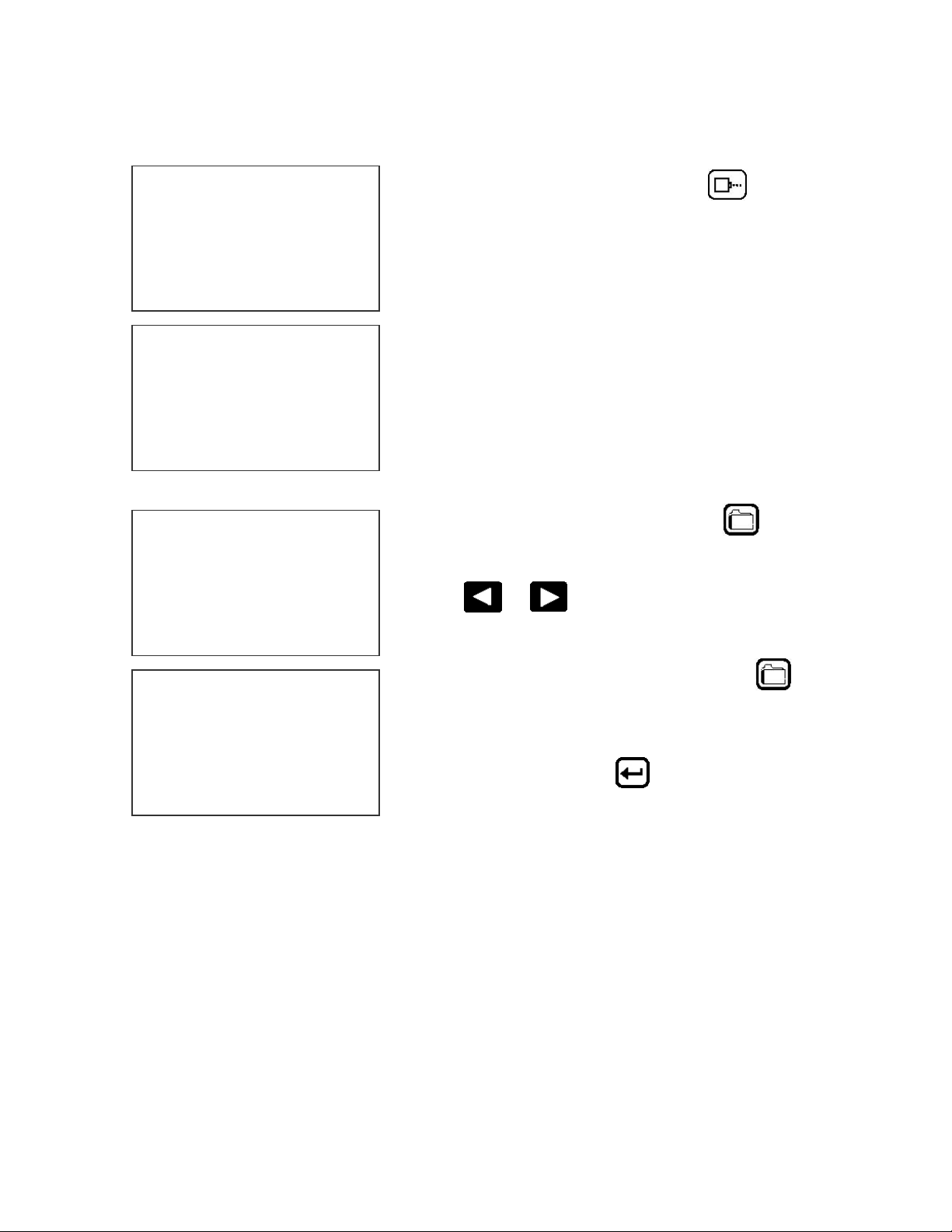
STORING A MESSAGE (LX 1 WITH OP 1, 1.5, 2, 3 OR LX 2)
LX x STOPPED
HD 1- - >SPEED=100
EXP 12/
MESSAGE # 1 LX x
PLEASE WAIT
MESSAGE # 1 LX x
MESSAGE STORED
EXP 12/
Press the GREEN STOP PRINT KEY
Note: There are up to 100 messages
stored in the hand held controller
(option dependent). This allows the user
to move the controller to another printer
and enter the same or other saved
message.
The upper right top line of the display
indicates the unit type the message was
prepared for.
Press the RED MESSAGE STORE key
The LCD display will display the message storage
screen
Use the or to select the desired storage
location
LX x STOPPED
HD 1- - >SPEED=100
EXP 12/
Press the RED MESSAGE STORE KEY a
second time and the current message appears in
the selected location and is stored.
Press the ENTER key
STOPPED prompt.
to return to the
12 EVOLUTION LX SYSTEM MANUAL Issue 1.0 5 DEC 2009
Page 16
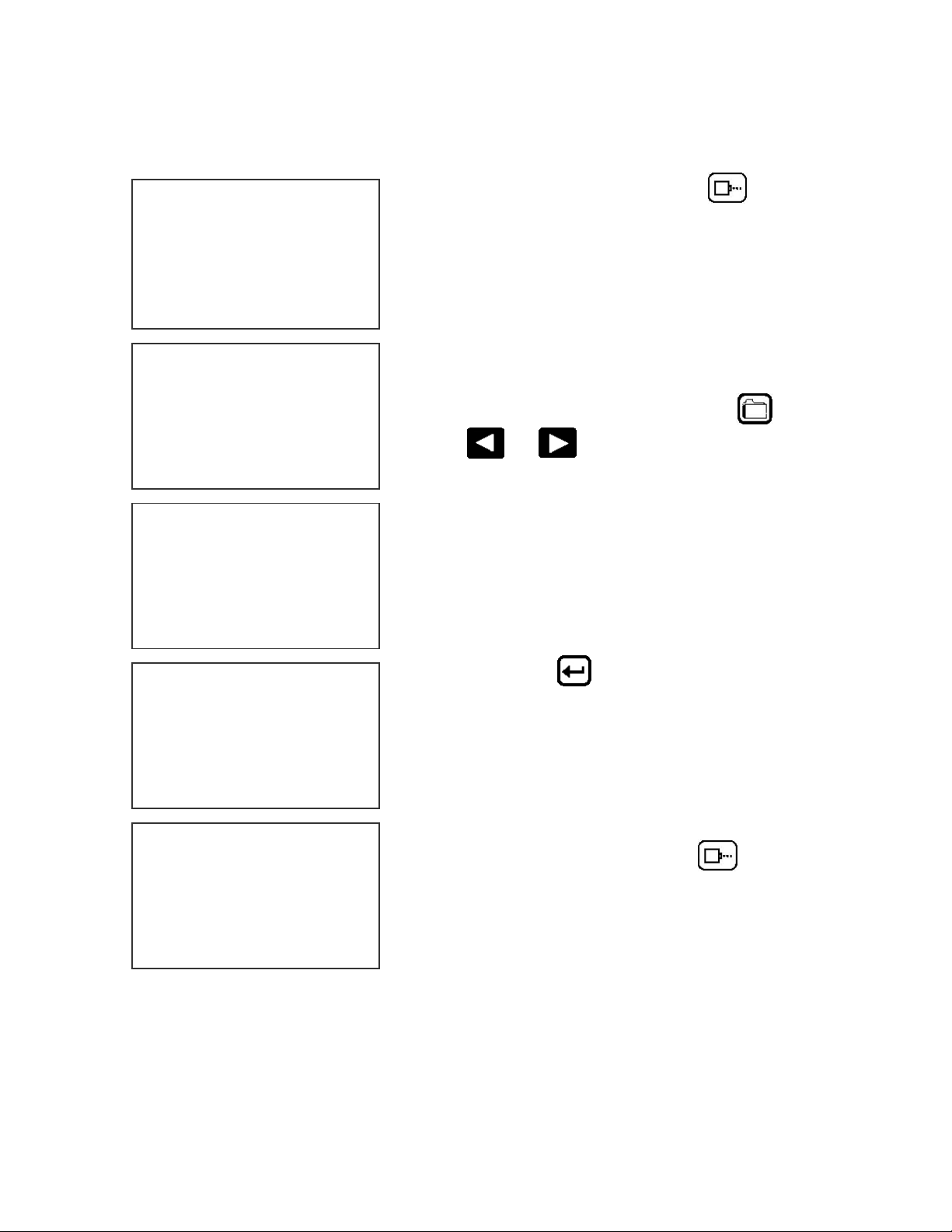
LOADING A MESSAGE (LX 1 WITH OP 1, 1.5, 2, 3 OR LX 2)
LX x STOPPED
HD 1- - >SPEED=100
EVOLU
MESSAGE # 1 LX x
PLEASE WAIT
MESSAGE # 1 LX x
EXP 12
Press the GREEN STOP PRINT KEY
Note: In option pack 1 there is a
maximum of 50 messages stored.
Option pack 1.5 or above, increases
message storage to 100 messages.
Press the RED MESSAGE STORE key and
use the or keys to select the desired
message
The top line of the display also indicates the
printer style that the current stored message was
created for. Attempting to load a stored message
into a different printer style will result in an
“SYSTEMS INCOMPATIBLE” message
LX x STOPPED
HD 1- - >SPEED=100
EXP 12
LX x PRINTING
HD 1- - >SPEED=100
EXP 12
Press the ENTER key to load the selected
message and return to the STOPPED Mode. The
selected message will be displayed on the LCD.
Press the GREEN print enable key
the PRINTING Mode
to enter
13 EVOLUTION LX SYSTEM MANUAL Issue 1.0 5 DEC 2009
Page 17
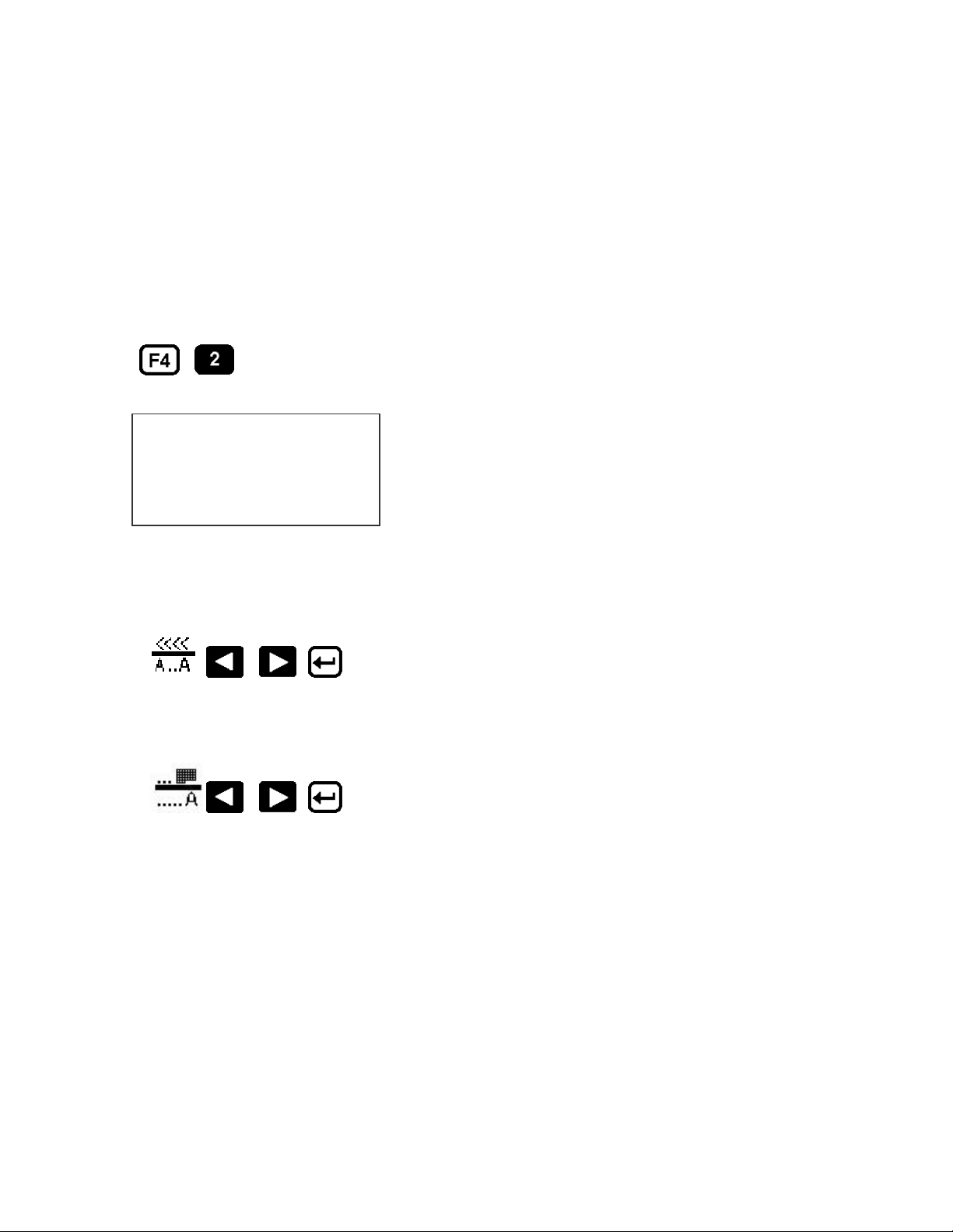
EVOLUTION LX QUICK SETUP
Each time a new print cartridge is installed the system automatically profiles the
correct operating parameters and current remaining ink level for the newly
installed cartridge. These parameters set the required voltage and firing
parameters to produce consistent results without user intervention.
NOTE: USING OTHER THAN AUTHORIZED CARTRIDGES MAY CAUSE
UNDESIRABLE RESULTS.
To view the current ink level press the following keys in order:
<< -- INK -- >>
100 %
OTHER KEY EXIT
The LINE SPEED may be set in either the PRINTING or STOPPED mode.
Set the line speed by:
This screen indicates the ink level remaining.
This value is approximate as it does not take
into account any service wipes or external
priming/cleaning functions.
Press any key to return to the STOPPED mode.
The PRINT DELAY may be set in either the PRINTING or STOPPED mode.
Set the print delay by:
NOTE: Each increment or decrement changes the delay by the pre-defined
amount. Each count increases or decreases the print delay by approximately
0.050” (1.27mm)
You may continue to experiment with line speed and print delay until the desired
code registration on the product is achieved.
14 EVOLUTION LX SYSTEM MANUAL Issue 1.0 5 DEC 2009
Page 18
PART 2: OPERATION PROCEDURES
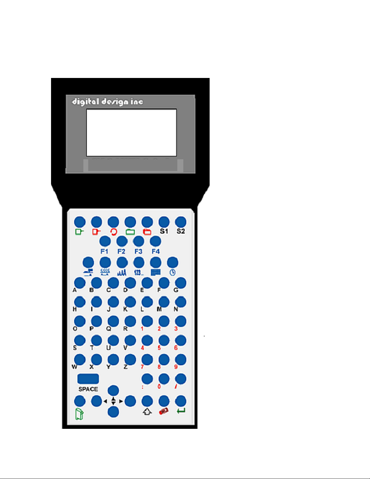
OVERVIEW
CONTROLLER AND LCD
The keypad on the print
station, pictured here, contains
64 keys. The LCD will display
various messages to assist in
programming on the upper half
LX x STOPPED
HD 1 - ->SPEED= 100
EVOLU
EVOLUTION CODERS
of the display. The lower half
of the display will show the
actual message in a
WYSIWYG (What You See Is
What You Get) format.
The system operates is 3 basic
modes. They are: PRINTING,
STOPPED, and MESSAGE
ENTRY Mode. In PRINTING
Mode the majority of the keys
on the keypad are disabled to
avoid inadvertent changes.
When in PRINTING Mode the
Top line of the LCD will display
PRINTING.
The STOPPED Mode is used
to change the functions of the
printer. When in the
STOPPED Mode the display
will show STOPPED on the top
line.
The Message Entry Mode is
used to create or modify
printable codes, when in this
mode the top line of the display
will show MESSAGE ENTRY.
The 4 keys on the second row
are the function keys F1
through F4. They each consist
of submenus for modifying
various printer functions. Their
specific menus are detailed
later in this section.
The next two rows of keys with
icon legends directly control
specific parameters of the
printer as follows.
1 EVOLUTION LX SYSTEM MANUAL Issue 1.0 5 DEC 2009
Page 19
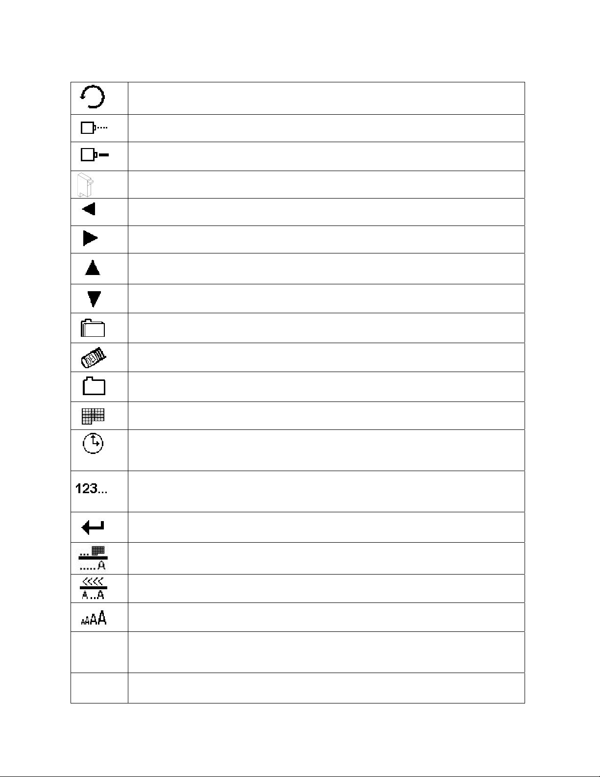
KEYPAD KEY DESCRIPTIONS
This is the manual cycle key. When in the STOPPED Mode, pressing this
key causes the printer to print one code.
.
This is the Print key. Use it to place the unit in the PRINTING or
STOPPED Mode
This is the Purge key. Use it to purge ink for maintenance purposes. The
unit must be in the STOPPED Mode to use this key.
This is the Head Select key. Use it to select the address of the head to be
S1
S2
communicated with. Or day of week in MESSAGE ENTRY mode.
Use this arrow to decrease values, and use it to move the cursor in the
message line while editing the message.
Use this arrow to increase values and use it to move the cursor in the
message line while editing the message.
Use this arrow to move the cursor between the message lines while in
Edit mode and building a message. Increment LCD contrast
Use this arrow to move the cursor between the message lines while in
Edit mode and building a message. Decrement LCD contrast
This key is the Message Storage key. Use it to store and to recall
individual messages. Enters prefix in MESSAGE ENTRY mode.
This is the Delete key. Use it to backspace to delete a character when
mistyped as well as to exit from certain menus.
This is the Message Entry key. Use this key to enter the MESSAGE
ENTRY mode, to input a code or to edit a message.
The Date key. Use this key to enter the Date in MESSAGE ENTRY Mode.
(LX1 WITH OP 2 or above or LX 2). Change Date in STOPPED Mode.
The Time key. Use this key to enter the Time in MESSAGE ENTRY
Mode. (LX1 WITH OP 2 or above or LX 2). Change Time in STOPPED
Mode.
This is the Sequence Number or Lot Counter key. Use this key to enter
the Sequence Number in MESSAGE ENTRY Mode. (LX1 WITH OP 2 or
above or LX 2). Sets SEQ/LOT operating parameters in STOPPED mode.
This is the Enter or Return key. When pressed, the unit will accept input
and exit certain menus.
This key selects the Print Delay and Offset Dates (1 or 2) in MESSAGE
ENTRY mode (LX1 WITH OP 3 or LX 2)
This key selects the Line Speed and the shift code in the MESSAGE
ENTRY mode (LX1 WITH OP 3 or LX 2)
This key selects the Font size in the MESSAGE ENTRY mode.
In the STOPPED Mode pressing this key displays the current fonts loaded
Pressing this key while in the MESSAGE ENTRY mode enters special
characters. In STOPPED mode enter the Prefix for Mixed Raster in the
LX2.
This key enters special customer Logos in MESSAGE ENTRY mode. In
STOPPED or PRINTING the S2 key reverses LCD colors.
2 EVOLUTION LX SYSTEM MANUAL Issue 1.0 5 DEC 2009
Page 20

TURNING ON THE PRINT STATION FOR THE FIRST TIME
To turn the print station on insert the power jack into
LX x STOPPED
HD1- - >SPEED=100
the DC power connector.
There is no on/off switch or power
indicator. When the power is first applied
both red and green LED’s will flash
EVOLU
several times indicating a power up
sequence. The LCD on the hand held
controller will be illuminated indicating a power on condition.
The first time the print station is turned on, as received from the factory, the LCD
will look like the illustration above. Each line gives important information
regarding the system:
The Top line indicates the operating mode of the unit: “STOPPED” when in
STOPPED Mode, “ PRINTING” when in PRINTING Mode (DEFAULT), and
“MESSAGE ENTRY” when in message entry mode. The first several characters
on the top line indicated the system type.
The 2nd line shows the print head currently selected, the direction of travel for the
product and the programmed SPEED, or encoder divider when using an external
encoder, which only can be viewed in the PRINTING mode.
The lower half of the display shows the message available for printing.
CHECKING SYSTEM INFORMATION
Verify system information by pressing the V key
CONTROLLER 2.0
PRINTER 3.06A
PRINTER SN284955
ANY KEY TO EXIT
the next+ indicates option pack 2 and the last + indicates option pack 3. All four
+ signs indicate option pack 3 or the LX 2 system.
on the hand held controller keyboard. The LCD
screen will display the software, firmware, serial
number and options enabled. Enabled options
are indicated on the second line as a series of +
characters where the first + indicates option
pack 1, the second + indicates option pack 1.5
CHECKING LOADED FONTS
LX 1 ACTIVE FONTS
2 LINE fontname
1 LINE fontname
ANY KEY TO EXIT
LX 2 ACTIVE FONTS
4 LINE font name
3 LINE font name
2 LINE font name
LX 1 Press the FONT key in the
STOPPED Mode to check what 2 fonts are
currently loaded in the print head.
LX 2 Press the FONT key in the
STOPPED Mode to check what 4 fonts are
currently loaded in the print head.
1 LINE font name
ANY KEY TO EXIT
3 EVOLUTION LX SYSTEM MANUAL Issue 1.0 5 DEC 2009
Page 21
CHANGING SYSTEM DATE AND DAY OF WEEK CODES
(LX1 WITH OP 2,3
PRESENT SETTING
ANY CHANGES Y/N
01/04/00
PRESENT SETTING
ANY CHANGES Y/N
01/04/00
ENTER MONTH-
PRESENT SETTING
ANY CHANGES Y/N
01/04/00
ENTER DAY-
PRESENT SETTING
ANY CHANGES Y/N
01/04/00
ENTER YEAR-
< - - SELECT - - >
DAY OF WEEK- 1
DAY FORMAT
1= NUMERIC
2= LETTERS
PRESENT SETTING
ANY CHANGES Y/N
04/23/05
or LX 2)
When the unit is in the STOPPED Mode
pressing the DATE key allows the user to
change the system date. If there are no
changes press the N key to return to the
STOPPED Mode.
Press the Y key to change the date.
The system will prompt the user first for the
Month (enter 2 digits), then the Day (2 digits)
and finally the year (2 digits).
After the date is entered the system requests
the actual date day of week. This parameter is
usually set to 1 for Sunday, 2 for Monday etc.
The day of the week can be entered into a
message as either a number 1-7 or as a letter
A-G. The day of the week is entered into a
message by pressing the key while in the
MESSAGE ENTRY mode.
After the data is entered the system displays
the currently entered date and pressing the N
key returns the user to the STOPPED Mode,
or press Y to the correct the date.
4 EVOLUTION LX SYSTEM MANUAL Issue 1.0 5 DEC 2009
Page 22

CHANGING SYSTEM TIME AND DATE ROLL OVER TIME
(LX1 WITH OP 2,3 or LX 2)
TIME SETTINGS
1= SET TIME
2= DATE CHANGE TIME
PRESENT SETTING
ANY CHANGES Y/N
23:05
PRESENT SETTING
ANY CHANGES Y/N
23:05
ENTER HOURS -
PRESENT SETTING
ANY CHANGES Y/N
23:05
ENTER MINUTES -
PRESENT SETTING
ANY CHANGES Y/N
13:50
TIME SETTINGS
1= SET TIME
2= DATE CHANGE TIME
DATE TIME CHANGE
ANY CHANGES Y/N
00:00
When the unit is in the STOPPED Mode
pressing the TIME key allows the user to
change the system time or date change time.
Press the 1 key to display the current time
Select the N key if the time is correct and
return to the STOPPED Mode.
Press the Y key to change to the correct time.
Enter the correct hours (2 digits) followed by
the correct minutes (2 digits). The screen
displays the corrected time. Press the Y key to
make further changes or N key to return to the
STOPPED Mode.
Notice the time is in 24-hour format.
The Date Change option is enabled by
selecting option 2. This feature allows the date
to roll over at a specified time other than 00:00
(12:00am midnight). For example if the start of
a new shift day occurs at 06:00 the date will be
changed each day at 6:00AM.
Selecting Y allows changing of the roll over
time. Setting this parameter to 00:00 sets the
default rollover time to midnight.
5 EVOLUTION LX SYSTEM MANUAL Issue 1.0 5 DEC 2009
Page 23
DATE TIME CHANGE
ANY CHANGES Y/N
00:00
ENTER HOURS -
DATE TIME CHANGE
ANY CHANGES Y/N
00:00
ENTER MINUTES -
RESET CLOCK
ENTER HOURS -
RESET CLOCK
ENTER MINUTES -
Similar to entering the time, first enter the
hours then at the next prompt enter the
minutes. Remember the time is entered in
military time.
Entering 06:00 sets the date change time at
6:00AM.
Enabling this function requires resetting the
current correct time.
Enter both the current time in hours and
minutes.
This resets the correct time and establishes a
new Date Rollover Time.
LCD BACKLIGHT AND CONTRAST CONTROL
The LCD backlight and contrast may be set from the hand held controller
keyboard and is applicable in both the PRINTING and STOPPED mode.
The S2 key causes the LCD to display as either white letters on a blue
background or blue letters on a white background. This key is an alternate action
key.
Backlight contrast may be controlled using the
The user may set these parameters to best suit the application.
keys on the keyboard.
6 EVOLUTION LX SYSTEM MANUAL Issue 1.0 5 DEC 2009
Page 24

SETTING PRINTING PARAMETERS
DEFINITIONS
There are two parts to programming the EVOLUTION LX ink jet printer,
• Configuring the operations parameters, (character width, delay, etc.) and
• Creating the message.
MODES OF OPERATION
The system operates in 3 basic modes. They are: PRINTING, STOPPED, and
MESSAGE ENTRY Mode.
In PRINTING Mode the majority of the keys on the keypad are disabled to avoid
inadvertent changes. When in PRINTING Mode the Top line of the LCD will
display PRINTING.
The STOPPED Mode is used to change the functions of the printer. When in the
STOPPED Mode the display will show STOPPED on the top line.
The Message Entry Mode is used to create or modify printable codes, when in
this mode the top line of the display will show MESSAGE ENTRY.
PRINTING AND STOPPED MODE
LX x PRINTING
HD1- - >SPEED=100
EVOLU
LX x STOPPED
HD1- - >SPEED=100
Mode. To enter STOPPED Mode, press .
When in the PRINTING Mode the screen will look
like the screen on the left. When PRINTING is
seen on the LCD, the unit will print as product
passes in front of the printer. To enter PRINTING
Mode, press .
When in the STOPPED Mode the screen looks
like the illustration at left. When STOPPED the
printer will not print when product is moved past
the printer.
In STOPPED Mode, access can be made to the
menus under the function keys, F1 through F4
icon control keys plus access to Message Entry
7 EVOLUTION LX SYSTEM MANUAL Issue 1.0 5 DEC 2009
Page 25
MENU STRUCTURE
In the STOPPED Mode, access is allowed to the menu structure for basic
parameters. The menus reside within the function keys, F1 through F4. In order
to select one of the parameters, press the number key that corresponds to the
desired parameter.
The F1 key, when pressed, brings up the menu as shown below.
1=CHAR. SPACING
2=EXT. ENCODER
3=DATE OFFSET
4=BARCODE
The F2 key, when pressed, brings up the menu as shown below.
1=DIRECTION
2=PRINT INVERSE
3=PRODUCT DETECT
4=AUTO REPEAT
The F3 key, when pressed, brings up the menu as shown below.
1=PRODUCT COUNT
2=SHIFT CODE
3=DATE FORMAT
4=TIME FORMAT
The F4 key, when pressed, brings up the menu as shown below.
1=LANGUAGE
2=INK SUPPLY
3=SET UNIT I.D.
4=LOAD CARD
NOT AVAILABLE
#3 VALID IN LX1 WITH OP 3 or LX 2
#4 VALID IN LX 2 MODEL
#4 VALID WITH ANY OP1, 2,3 OR LX 2
#1 VALID IN LX1 WITH OP 3 OR LX 2
#2 VALID IN LX1 WITH OP 3 OR LX 2
#3 VALID IN LX1 WITH OP 2, 3 OR LX 2
#4 VALID IN LX1 WITH OP 2, 3 OR LX 2
Selecting an option that is not available will
display the screen as pictured on the left
indicating that the option is not available.
ANY KEY TO EXIT
8 EVOLUTION LX SYSTEM MANUAL Issue 1.0 5 DEC 2009
Page 26
F1 MENU
1=CHAR. SPACING
Place the unit in the STOPPED Mode and press
2=EXT. ENCODER
3=DATE OFFSET
4=BARCODE
future system expansion.
Press the correct number to make changes to that
parameter. Those selections not available will
display NOT AVAILABLE. They are reserved for
1 = CHARACTER SPACING
< - - SELECT - - >
# OF SPACES- 1
This parameter controls the amount of space
between characters in the code. Spacing can be
varied from 1 to 25 columns. Use this control to
make printed codes more legible when code is
. The screen shown to the left is produced.
compressed. Press the
change the value. Press once the desired value is displayed.
then press or to
2 = EXT. ENCODER
ENCODER
1=INTERNAL
2=EXTERNAL
aspect ratio character (300 dpi vertical and horizontal) or compressed by setting
the print head line speed faster than the actual line speed, or expanded by
changing the internal speed slower than the actual line speed.
In the event there is an acceleration or deceleration to the production line, or
there is a requirement to guarantee accurate aspect ratio, such in the case of
barcodes, an external encoder is necessary. Press
encoder. While external encoder is selected the LINE SPEED key
the expansion and compression of the printed message. NOTE: WHEN
PRODUCING BARCODES IT IS NECESSARY TO PRODUCE A PERFECT
ASPECT RATIO CHARACTER.
Swath height is 0.500 (1/2”) / 150 vertical dots = 0.0033” between vertical dots
Therefore to print a perfect aspect ratio character requires an encoder pulse
every 0.0033”. The encoder range adjustment is from 0 to 7 and assuming the
mean is a count of 4 then by connecting an encoder that produces a pulse for
each 0.000825” the correct character aspect ratio can be achieved. This allows
either compression or expansion of the printed text.
In STOPPED mode the external encoder is ignored and the internal time base is
used to print a message.
Press to select internal time base. This
parameter controls the source of the time base used
for printing. Each vertical column printed requires a
signal necessary to produce a character
representative of the line speed of the production
line. The printer can be set to produce a perfect
to select external
will adjust
9 EVOLUTION LX SYSTEM MANUAL Issue 1.0 5 DEC 2009
Page 27
3 = DATE OFFSET (LX1 WITH OP 3 ONLY OR LX 2)
This selection allows the user to preset the number of
DATE OFFSET
1 DATE OFFSET 1
2 DATE OFFSET 2
DATE OFFSET
USE KEYS 0->9
# OF DAYS = 0100
days used in the date offset calculation to a maximum
of 9999 days. The format of the date offset can be
different than a normal date and may be set with the
F3 #3 option DATE FORMAT.
There are two date offset functions, and each may be
set independently.
Select option 1 or 2 to enter the desired offset days.
4 = BARCODE TYPE (LX 2 MODEL ONLY)
< - - SELECT - - >
CODE 39
< - - SELECT - - >
UPC A
< - - SELECT - - >
MIN. BAR WIDTH= 5
< - - SELECT - - >
ADDED SPACE = 0
< - - SELECT - - >
QUIETZONE WIDTH
75
This parameter determines the barcode type to be
entered into a message. As standard the
EVOLUTION LX 2 contains 8 barcode symbologies,
which are: UPC-A, UPC-E, EAN-8, EAN-13, CODE
39, CODE 128B, CODE 128C AND INTERLEAVED
2 OF 5.
Press or to change the barcode type and
press once the desired type is displayed.
The default system parameter establishes that the
normal size of a narrow bar is equal to 5 vertical
columns. This value, which is variable from 3 to 15,
is selectable depending on the overall length of the
barcode to be printed and the bleed factor of the ink
on the surface. This value sets both the light and
dark bars nominal width.
The added space parameter allows the user to
insert extra columns to a normal light bar width to
allow for the bleed factors associated with various
substrates. Valid entries are from 0 to 3 extra
spaces.
The quiet zone is the space before and after a
barcode that must be kept blank. Each count is
equal to one vertical column. In proper aspect ratio
each column is 0.0033” thus a count of 75 would
leave 0.247” before and after the barcode.
10 EVOLUTION LX SYSTEM MANUAL Issue 1.0 5 DEC 2009
Page 28

ADD CHECK DIGIT
1 = YES
2 = NO
ADD MAN READABLE
1 = YES
2 = NO
ADD GUARD BARS
1 = YES
2 = NO
Barcode reliability is directly related to the substrate and linearity of the
production line. Care should be taken to ensure that the production environment
is conducive to printing barcodes. For example barcodes are susceptible to
vibration (bounce) found on roller style conveyers where flat belt types are
preferable. Acceleration and deceleration components will add a skew factor to
the barcode as will slippage between the product and production line. Refer to
Appendix A for further details on “Producing a Reliable Barcode”.
Check digits may be added to any of the
imbedded symbologies by selecting option 1.
This parameter adds a man readable set of
characters directly beneath the barcode being
printed, and is valid for all barcode types.
If man readable characters are enabled the user
has the option of enabling or disabling guard
bars.
11 EVOLUTION LX SYSTEM MANUAL Issue 1.0 5 DEC 2009
Page 29
F2 MENU
Place the unit in the STOPPED Mode and press
1=DIRECTION
2=PRINT INVERSE
3=PRODUCT DETECT
4=AUTO REPEAT
produced. Press the correct number to make
changes to that parameter
NOTE: OPTION 4 ONLY APPEARS IF LX 1
WITH OP 1,2,3 OR LX 2
. The screen shown to the left is
1 - DIRECTION
The arrow shown on the LCD’s third line should
< - - SELECT - - >
LINE DIRECTION
< - - - -
agree with the direction of product travel. Press
or to change direction. Press for the
printer to accept the change.
2 - PRINT INVERSE
CODE ORIENTATION
1 = NORMAL PRINT
This parameter allows the code to print right side
up or upside down. Press for normal print or
for upside down codes. Save the choice by
2 = UPSIDE DOWN
pressing . Upside down printing will normally
require a change in direction.
3 – PRODUCT DETECT
PRODUCT DETECT
1 = INTERNAL
2 = EXTERNAL
necessary to sense a portion of the product not directly in front of the print head
then an external product detect sensor must be used. This setting also allows the
EVOLUTION LX to be controlled from other sources, like a PLC.
This menu selection allows the user to select the
source of the product detect feature. Press
and then to use the internal product
detect sensor located at the front of the printer
just below the print head. If it becomes
12 EVOLUTION LX SYSTEM MANUAL Issue 1.0 5 DEC 2009
Page 30
4 - AUTO REPEAT (LX1 WITH OP 1, 2 OR 3 OR LX 2) *********
< - - SELECT - - >
REPEAT TIME= 0
time delay adds or subtracts a distance equivalent to the pre-defined setting.
Save your choice by pressing . The maximum repeat spacing is 255 counts
where each count is equal to 80 character columns or 0.250”. This allows for a
total displacement of 63.75”. Setting a print delay that uses the same
mathematical equation can increase this number. Thus a total displacement of
26.92” can be realized.
< - - SELECT - - >
1=UPDATE CODE
2=SAME CODE
When the UPDATE CODE option is enabled then variable field data; for
example a sequence number is updated on each printed message. Selecting the
SAME CODE feature will, in the above example, print the same sequence
number on all subsequent prints on the same product. Variable data will only be
updated when the next product passes in front of the printer.
An example of this is printing on a piece of plasterboard. With the count disabled
a sequence number, for example, will print the same serial number N times
across the length of the plasterboard. When the next board passes in front of the
print head the sequence number will be updated.
This option enables the unit to continuously print
repeated codes at specified time intervals along
the entire length of the product. A time of 0
disables the Auto Repeat option. Use or
to change the repeat time. Each number in the
If a repeat time is greater than zero then the
auto repeat function is enabled. After entering a
repeat time the user is prompted to update the
printed data variable field contents or use the
same information for all printed messages.
13 EVOLUTION LX SYSTEM MANUAL Issue 1.0 5 DEC 2009
Page 31

F3 MENU
1= PRODUCT COUNT
2= SHIFT CODE
3=DATE FORMAT
4=TIME FORMAT
1 – PRODUCT COUNT (LX1 WITH OP 3, OR LX 2)
The product counter is a non-printable entity,
PRODUCT COUNT
CHANGES Y / N OR C
08:00 - - > 17:00
COUNT = 000000
and must be read after the end of the set time
period. The counter indicates each print cycle
sensed by the product detect circuitry, whether
internal or external. Depressing the C key will
clear the counter.
If there are no changes press the N key.
PRODUCT COUNT
START TIME
08:00 - - > 17:00
ENTER HOURS-
To change the settings depress the Y key.
All times are in Military Time 00:00 to 23:59
hours.
Enter the start time HOURS.
PRODUCT COUNT
START TIME
08:00 - - > 16:00
ENTER MINUTES-
At the next screen prompt enter the start time
MINUTES
PRODUCT COUNT
STOP TIME
08:00 - - > 16:00
ENTER HOURS-
PRODUCT COUNT
STOP TIME
08:00 - - > 16:00
ENTER MINUTES-
PRODUCT COUNT
CHANGES Y / N OR C
08:00 - - > 17:00
The system then prompts the user for the STOP
TIME.
Enter both the stop time HOURS and then the
MINUTES.
The newly entered data is re-displayed for
verification or correction if necessary Press the
Y key to change the data or the N key to finish
and return to the STOPPED MODE
COUNT = 000000
14 EVOLUTION LX SYSTEM MANUAL Issue 1.0 5 DEC 2009
Page 32
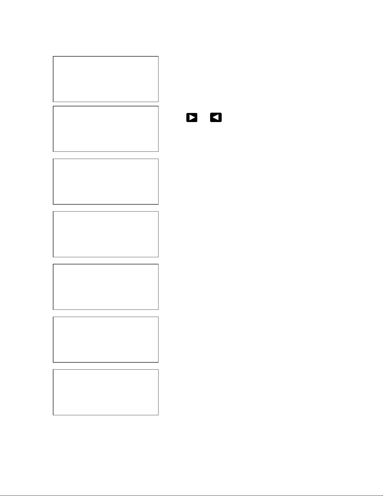
2 – SHIFT CODE (LX1 WITH OP 3, OR LX 2)
1= PRODUCT COUNT
2= SHIFT CODE
3=DATE FORMAT
4=TIME FORMAT
Shift codes may be encoded directly in the
printable message. The printer can print 6
individual shift codes. Each shift code contains a
unique start time and alpha/numeric code to be
printed.
ADJUST SHIFTS
< - - SELECT - - >
SHIFT 1 07:00 A
ANY CHANGES Y/N
ADJUST SHIFTS
SHIFT 1
START TIME
ENTER HOURS -
ADJUST SHIFTS
SHIFT 1
START TIME
ENTER HOURS -
Press or to change the desired shift to
view or change.
The shift code option allows the user to enter 6
different shift times per day. Use the arrow keys
to select a shift and enter a Y to change a shifts
start time.
All times are in Military Time 00:00 to 23:59
hours.
Enter the correct start time HOURS for the shift
selected.
ADJUST SHIFTS
SHIFT 1
START TIME
ENTER MINUTES -
Enter the correct start time MINUTES for the
shift selected.
ADJUST SHIFTS
SHIFT 1
PRINT CODE -
ADJUST SHIFTS
< - - SELECT - - >
SHIFT 1 07:00 A
ANY CHANGES Y/N
CHARACTER IN THE PRINT CODE FIELD. THE SHIFT TIMES WILL BE DISPLAYED AS --:-FOR ALL DISABLED SHIFT TIMES.
Finally, enter the desired code to be printed in
the message. Legal characters are the letters A
to Z and the numbers 0 to 9.
The printer re-displays the data for the
selected shift for verification.
NOTE: THIS PROCEDURE MAY BE
REPEATED FOR ALL DESIRED SHIFTS
NOTE: TO DISABLE A SHIFT ENTER A SPACE
15 EVOLUTION LX SYSTEM MANUAL Issue 1.0 5 DEC 2009
Page 33

3 – DATE FORMAT (LX1 WITH OP 2, 3 OR LX 2)
Y
Y
j
Y
j
Press F3 to change the date formatting. Each of
1= PRODUCT COUNT
2= SHIFT CODE
3=DATE FORMAT
4=TIME FORMAT
CHANGE FORMAT
1=CALENDAR DATE
2=WEEKLY DATE
3=DATE OFFSET 1
4= DATE OFFSET 2
MONTH FORMAT
1=NUMERIC
2=LETTERS
DATE FORMAT
D=DAY M=MONTH
=YEAR J=JULIAN
dm/dd/dy
DATE FORMAT
D=DAY M=MONTH
=YEAR J=JULIAN
jj
DATE FORMAT
D=DAY M=MONTH
=YEAR J=JULIAN
jjyy
the following screens prompts the user to enter
the desired format for printing.
NOTE: THE USER MAY INDIVIDUALLY
CHANGE THE FORMAT OF BOTH THE
CALENDAR FORMAT AND THE DATE
OFFSET
NOTE: THE FOLOWING PROCEDURE
APPLYS TO BOTH CALENDAR AND OFFSET
DATE FORMATS.
Selecting the standard numeric format will
prompt the user to enter the format of the date in
standard number format.
The default as shipped from the factory is
dm/dd/dy, and may be modified as required.
If the offset format was selected the word DATE
is replaced with the word OFFSET x, where x is
either 1 or 2.
To change the format press the delete key and
the last line on the display will be erased. The
entire format will be erased and must be reentered.
Press either of the designator keys (i.e. M for
month) and the display will display the correct
code for the item selected. As an example enter
the Julian date and year. Press the J key
followed by the Y key. The code entered will
print the Julian date followed by the 2-digit year.
Notice no delimiters were selected, but may
have been entered by selecting the appropriate
key on the keyboard. Legal delimiters are the
colon (:), the forward slash (/) or the period (.) or
SPACE.
16 EVOLUTION LX SYSTEM MANUAL Issue 1.0 5 DEC 2009
Page 34

MONTH FORMAT
Y
j
Y
1=NUMERIC
2=LETTERS
DATE FORMAT
D=DAY M=MONTH
=YEAR
jjyy
DATE FORMAT
D=DAY M=MONTH
=YEAR
ddmmmyy
WEEKLY DATE
1=ENABLE
2=DISABLE
Entering either the current date or offset date in a message will result in the initial
date being printed for either function throughout the following week. Selecting
option 2 disables the function and returns the user to the STOPPED Mode.
Alpha characters may be selected by pressing
option 2.
Delete the current formatting by pressing the
Delete key.
Enter the desired Date Format and notice when
the M (month) is selected the display shows
mmm. Select the appropriate key on the
keyboard by entering in the desired code. Press
the Enter key to return to the STOPPED Mode.
The software performs a special function
allowing the user to set the current date to
change only at a certain day of the week. This
function is typically used in batch processing,
where a batch may be prepared on Sunday and
packaged from Monday through Friday of the
following week.
17 EVOLUTION LX SYSTEM MANUAL Issue 1.0 5 DEC 2009
Page 35

4 – TIME FORMAT (LX1 WITH OP 2, 3 OR LX 2)
Change the Time Format by selecting option 4.
1= NOT AVAILABLE
2= NOT AVAILABLE
3=DATE FORMAT
4=TIME FORMAT
NOTE: Delimiter characters like a : /
SPACE OR PERIOD code may be
entered to separate fields
TIME FORMAT
H=HOURS S=SECOND
M=MINUTES
hh:mm
TIME FORMAT
H=HOURS S=SECOND
M=MINUTES
hh
The factory default for time formatting is hh:mm
and may be changed as required. Press the
Delete key and the last line on the display is
erased.
Enter the desired format by pressing the H, M or S
keys, and select delimiters as required. Select H if
only hours are required.
Press the Enter key to return to the STOPPED
Mode.
18 EVOLUTION LX SYSTEM MANUAL Issue 1.0 5 DEC 2009
Page 36
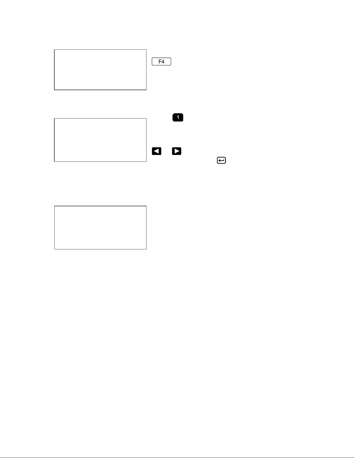
F4 MENU
1 = LANGUAGE
2 = INK SUPPLY
3 = SET UNIT I.D.
4 = LOAD CARD
Place the unit in the STOPPED Mode and press
. The screen shown at left is produced.
Press the number that corresponds to the
parameter you wish to change.
1 - LANGUAGE
Press and the screen will change like the
< - - SELECT - - >
ENGLISH
to the STOPPED Mode. Whenever language is chosen, all prompts and
commands shown on the screen will be in that language.
one on the left. The default language is English;
the other choices are Spanish, French or
German. Scroll through the choices using either
or . Once the desired language is shown
on the screen, press
. This will return the unit
2 - INK SUPPLY
The second line of the display shows the
REMAINING INK
100%
ANY KEY TO EXIT
Each cartridge is tested and profiled at the factory eliminating the burden of
personalizing each cartridge by the user. There are a number of tasks associated
with print cartridge profiling, as each print cartridge differs from another. The
correct drive voltage, pulse width timing, etc. must be calculated for optimum
operation.
percentage of ink remaining in the print
cartridge.
Each time a new cartridge is installed the system
automatically reads the cartridges remaining ink
supply.
NOTE: USING NON-AUTHORIZED CARTRIDGES MAY PRODUCE
UNDESIRABLE RESULTS
19 EVOLUTION LX SYSTEM MANUAL Issue 1.0 5 DEC 2009
Page 37

3 – SET UNIT I.D.
< - - SELECT - - >
SET HEAD # = 1
printers to affix a label indicating the unique ADDRESS number of the individual
printer.
Each printer can contain a unique address to
distinguish multiple printers when controlled by a
single hand held controller or computer data link
using an RS485 data link. The default for each
new printer is ADDRESS 1. Addresses can range
from 1 to 32. It is advisable when adding multiple
Note: To program a printer it must be connected directly to the
hand held controller, with no other printers connected.
Note: If several printers have the same address a NO
RESPONSE message or unreliable results may be displayed.
20 EVOLUTION LX SYSTEM MANUAL Issue 1.0 5 DEC 2009
Page 38

4 – LOAD CARD
LOADING FONTS (MENU SELECT 1)
EXECUTE LOADER
1=LOAD FONTS
2=LOAD LOGOS
3=LOAD OPTIONS
LOAD FONT
1= LOAD DEFAULTS
2= LOAD ALTERNATE
LOAD RESULTS
PLEASE WAIT
LOAD RESULTS
2 LINE fontname
1 LINE fontname
ANY KEY TO EXIT
MEMORY ERROR
NO FLASH CARD
ANY KEY TO EXIT
LOAD RESULTS
2 AF fontname
1 AF fontname
ANY KEY TO EXIT
NOTE: when optional fonts are loaded into the system the Data Flash Card
is encoded with the serial number of the unit and is valid only for the unit in
which the fonts were loaded.
The user can replace the existing FONT, add up
to six logos, or load optional software from a
Data Flash card, which is plugged into the top of
the printer. Select 1 to load a different font to
replace the current system font.
The screen to the left will appear and after a few
seconds a result will be displayed to indicate
NOTHING LOADED or the name of the newly
loaded font, logos or software upgrades.
This screen will be displayed if the data flash
card is either not present or cannot be read.
CHECK THAT THE DATA FLASH CARD IS
PROPERLY INSTALLED
A successful load will display the current font
names loaded into the print head. This screen
will be displayed when the default fonts are
loaded.
NOTE: LX 2 units display all 4 loaded fonts.
When loading alternate fonts the AF will replace
LINE for the alternate font or fonts loaded.
NOTE: LX 2 units display all 4 loaded fonts.
21 EVOLUTION LX SYSTEM MANUAL Issue 1.0 5 DEC 2009
Page 39
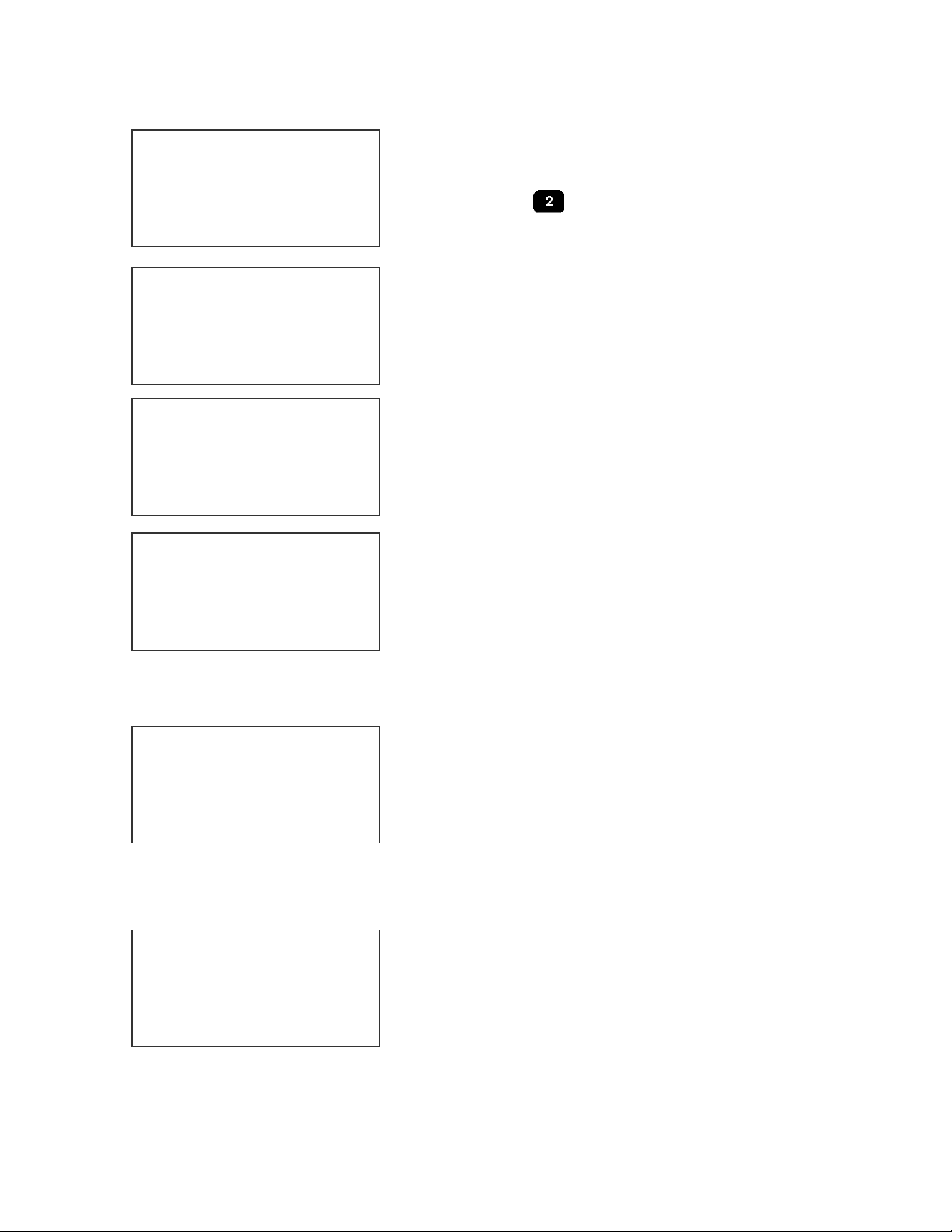
LOADING LOGOS (MENU SELECT 2)
EXECUTE LOADER
1=LOAD FONTS
2=LOAD LOGOS
3=LOAD OPTIONS
EXECUTE LOADER
PLEASE WAIT
MEMORY ERROR
NO FLASH CARD
ANY KEY TO EXIT
LOAD RESULTS
2 LINE 1 2 3
1 LINE 1 2 3
ANY KEY TO EXIT
LOADING OPTIONS (menu select 3)
EXECUTE LOADER
1=LOAD FONTS
2=LOAD LOGOS
3=LOAD OPTIONS
NOTE: when optional software is loaded into the system the Data Flash
Card is encoded with the serial number of the unit and is valid only for the
unit in which the software was loaded.
CONTROLLER 2.0
PRINTER 3.06A++++
PRINTER SN284955
ANY KEY TO EXIT
1, the second + indicates option pack 1.5 the third is option pack 2 and the last +
indicates option pack 3. NOTE: LX 2 systems display ++++ signs indicating a full
featured unit with 8 barcode symbologies.
The user can replace the existing FONT, add up
to six logos, or load optional software from a Data
Flash card, which is plugged into the top of the
printer. Select
head.
This screen will be displayed if the data flash card
is either not present or cannot be read.
CHECK THAT THE DATA FLASH CARD IS
PROPERLY INSTALLED
Displaying the number of logos as indicated in the
pictorial indicates successful loading.
The display indicates the number of logos loaded
for the 1 line or 2 line mode.
Loading logos overwrites the logos currently
existing.
Optional software may be added via Data Flash
Card to the basic unit to add features.
Verify system information by pressing the V key
on the hand held controller keyboard. The LCD
screen will display the software, firmware, serial
number and options enabled. Enabled options are
indicated on the second line as a series of +
characters where the first + indicates option pack
to load logos into the print
22 EVOLUTION LX SYSTEM MANUAL Issue 1.0 5 DEC 2009
Page 40
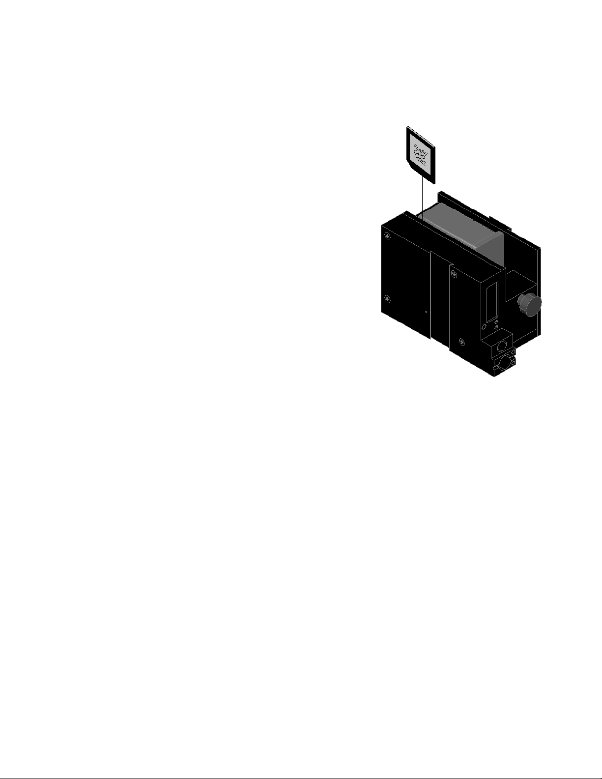
NOTE: THE FIGURE BELOW SHOWS THE CORRECT
ORIENTATION FOR INSERTING THE DATA FLASH CARD.
INSERT THE DATA FLASH CARD INTO THE SLOT
PROVIDED AT THE TOP OF THE PRINTER AS
SHOWN. NOTE THE ORIENTATION OF THE
LABEL ON THE CARD. PRESS THE CARD
COMPLETELY INTO THE SLOT. THE CARD
SHOULD BE REMOVED AFTER USE AND
STORED IN A SAFE PLACE. ONCE LOADED
(FONTS & OPTIONS) THE CARD IS SECURITY
LOCKED WITH THE SERIAL NUMBER OF THE
PRINTER AND WILL NOT OPERATE IN ANOTHER
PRINTER.
NOTE:
There are two fonts loaded into the EVOLUTION LX1 printer
at any one time, and four fonts loaded into the LX 2 printer.
Loading a new font will overwrite the existing font or fonts.
The LX 1 printer is shipped with a 1/2” font for a single line of
print and a 7/32” font for two lines of print.
Alternate fonts that are loaded replace the existing fonts.
The LX 2 system also includes a 1/8” and a 3/32” character font
for 3 and 4 line messages, respectively.
23 EVOLUTION LX SYSTEM MANUAL Issue 1.0 5 DEC 2009
Page 41
SETTING PRINT DELAY AND LINE SPEED
LINE SPEED – This setting adjusts the width of the printed message on the
product. This setting should be adjusted to produce the desired print on the
product. Line speed can be increased or decreased to stretch or compress the
message to fit the desired print area.
SETTING LINE SPEED
Normally, the system will be set to use the internal
< - - SELECT - - >
LINE SPEED = 100
this parameter. Once pressed, a new screen appears, as shown to the left.
Changes can now be made by using or . The range of values for
character width is 10 to 200. Once the desired number is chosen, press to
save your entry.
< - - SELECT - - >
ENCODER DIV = 1
time base for line speed control. The default value is
100, which creates a normal width character on a
line moving at 100 ft per min. The print can be
narrowed by increasing the number and widened by
decreasing the number. Pressing accesses
If external encoder is enabled and the unit is in the
PRINTING mode the user has the option of
adjusting the compression ratio of the printed
message. Changes may be made by using or
. Once the desired number is chosen, press
to save your entry.
24 EVOLUTION LX SYSTEM MANUAL Issue 1.0 5 DEC 2009
Page 42
SETTING PRINT DELAY
LX x STOPPED
HD1- - >SPEED=100
EVOLU
LX x PRINTING
HD1- - >SPEED=100
EVOLU
< - - SELECT - - >
PRINT DELAY= 100
DIFFERENT BUT CAN BE ESTIMATED BASED ON THE 16 COLUMNS PER
COUNT.
NOTE: Setting the line speed first, then adjusting the print delay may prove
to be the best starting point
Print delay is used to position a message on the
product at a location other than at the leading edge.
Access this parameter by pressing on the
keypad.
NOTE: This parameter may be set when the unit
is either in the PRINTING or STOPPED Mode
To change the value use either or . The
range of values for this parameter is 1 to 255. Each
increment represents 16 columns, approximately
.050” (1.5mm). Therefore, a delay of 255 would
approximate 12.75” (323.85mm). Once a number is
chosen, press to save the entry.
NOTE: THE DIMENSION INDICATED IS WHILE
PRINTING A PERFECT ASPECT RATIO
CHARACTER. WHEN PRINTING A
COMPRESSED OR EXPANDED CHARACTER
THE ACTUAL DIMENSIONAL NUMBER WILL BE
25 EVOLUTION LX SYSTEM MANUAL Issue 1.0 5 DEC 2009
Page 43
INPUT, EDIT OR DELETE MESSAGES
LX x STOPPED
HD1- - >SPEED=120
MESSAGE ENTRY
FONT 1 LINE
EVOLU
MESSAGE ENTRY
FONT 1 LINE
MESSAGE ENTRY
To input, delete or edit a message, the unit must be
in the STOPPED Mode. If the LCD reads
PRINTING, press . The screen should be
similar to the one shown at the left.
Enter the Message Entry mode by pressing .
The top portion of the screen will change as shown
on the left.
QUICK KEYS F1 beginning of line
F2 end of line
F3 delete entire message
The user has two options to edit or change a
message. If a new message is to be entered press
the key to delete the entire existing message.
For example, to produce a 1/2” tall 1 LINE message,
press the font key until the 1/2“ font size is
FONT 1 LINE
DM.DD.
MESSAGE ENTRY
FONT 2 LINE
BEST BY
EXP 12/01/2004
LX x STOPPED
HD1- - >SPEED=120
BEST BY
EXP 12/01/2004
shown, and enter EXP followed by the key.
This enters the DATE OFFSET (select 1 or 2 for
correct offset date) as defined in the F1 menu.
To place two lines use the
mode. Press the key to delete the entire
message. Press the to select which line
the data will be entered on. Enter BEST BY. The
pictorial at the left shows two lines of 2 LINE
character size. To enter and print only 1 line of 2
LINE select the line and enter data to that line only.
Once the message line(s) is complete, save the
change by pressing .
NOTE: USE THE DATE OFFSET KEY TO
ENTER AN EXPIRATION DATE.
to select 2 LINE
26 EVOLUTION LX SYSTEM MANUAL Issue 1.0 5 DEC 2009
Page 44
MESSAGE ENTRY
FONT 1 LINE
BEST BY
EXP 12/01/2004
MESSAGE ENTRY
FONT 1 LINE
BEST BY
EXP
MESSAGE ENTRY
FONT 1 LINE
BEST BY
EXP 12/31/2004
MESSAGE ENTRY
FONT 1 LINE
BEST BY
EXP 12/01/2014
< - - SELECT - - >
!#
$&( )*+=¢ŇẾỖ
LX x STOPPED
HD1- - >SPEED=120
BEST BY
EXP 12/01/2014
Continue to build the message or press to save the message and return to
the STOPPED Mode.
The second option is to replace characters by using
the key or moving the cursor over a character to
be replaced. When the MESSAGE ENTRY mode is
entered the cursor is placed at the end of the line.
Pressing the key will delete the last character on
the line. Successive ’s will continue to delete the
last character on a line.
At the left the characters 12/01/2004 were deleted..
NOTE: THERE IS NO INSERT FUNCTION
Enter the correct data, in this case 12/31/2004.
NOTE: in this case since the alpha/numeric
characters for the date were entered the field will
not automatically adjust for the next data rollover.
The user must use the DATE key for proper
operation.
The alternative approach if just a few characters are
to change is to use the or to place the cursor
just to the left of the character to be changed and
retype the correct character. In this example the
12/31/2004 WAS CHANGED TO 12/01/2014.
Symbols are inserted by pressing
Message Entry mode, position the cursor where a
symbol is needed and press
show a line of symbols as presented on the left.
Position the cursor by pressing or
immediately to the left the special character to be
inserted and press
.
. The screen will
. When in
LX 1 messages may contain up to 2 lines of text, while LX 2 may
contain up to 4 lines of text. Selecting different message lines is
accomplished by pressing the font key
until the appropriate
line designation is displayed.
27 EVOLUTION LX SYSTEM MANUAL Issue 1.0 5 DEC 2009
Page 45
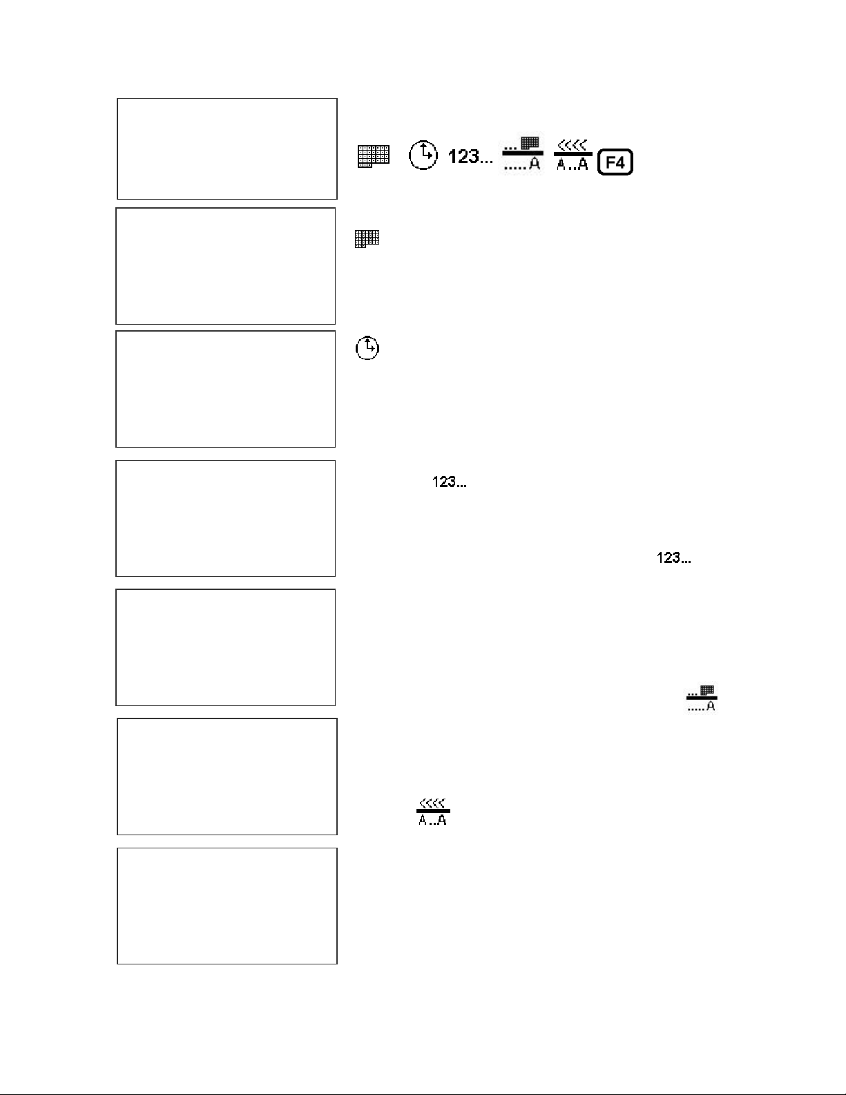
MESSAGE ENTRY
- - - - FONT- 1 LINE
Enabling variable field programming requires the
use of the special function keys.
MESSAGE ENTRY
- - - - FONT- 1 LINE
DM/DD/
MESSAGE ENTRY
- - - - FONT- 1 LINE
MESSAGE ENTRY
#### FONT- 1 LINE
MESSAGE ENTRY
- - - - FONT- 1 LINE
To enter a date that automatically changes use the
key. The current date format as set in the F3
menu is entered into the message.
To enter a time that automatically changes use the
key. The current time format as set in the F3
menu is entered into the message.
Sequence numbers may be added to a message
with the key. Note when the key is
depressed the four ---- are changed to ####
indicating a sequence number field. After entering
the correct sequence number press the key
to terminate the sequence field. The maximum
number of digits allowable is 9 numeric characters.
Refer to the following page for
Sequence or Lot counter setup and
selection.
Date offset codes are entered by using the
MESSAGE ENTRY
< < < < FONT- 1 LINE
MESSAGE ENTRY
- - - - FONT- 1 LINE
S
28 EVOLUTION LX SYSTEM MANUAL Issue 1.0 5 DEC 2009
key. The user may select offset 1 or 2 at data
entry time.
The correct date offset format as defined in the F3
menu is entered into the message.
Use the key to enter a shift code.
Shift codes are defined in the F3 menu and will
automatically change at the appropriate shift
times. The shift designator S is displayed to
indicate the data entry.
Page 46

SEQUENCE NUMBER LOT COUNTER SETUP AND SELECTION
Y
Y
Sequence number format is programmable in the
SEQ. NUMBER
1= COUNT UP
2= COUNT DOWN
CLEAR SEQ# FIELD
ES OR NO Y/N
COUNTER LIMIT
000000000
ANY CHANGES Y/N
COUNTER LIMIT
ANY CHANGES Y/N
ENTER #000000000
COUNTER LIMIT
ANY CHANGES Y/N
ENTER #000005000
LOT COUNTER
1=ENABLE
2=DISABLE
CLEAR LOT# FIELD
ES OR NO Y/N
UPPER LIMIT
STOPPED Mode by pressing the key. The
counter may be set to count either up or down by
selecting number 1 or 2. Pressing enter advances
the user to the next menu prompt.
Clearing the sequence field resets the counter to
their initial settings.
The next prompt allows for changes in the
sequence limit field. Selecting Y allows the user to
enter the desired maximum (minimum for down
count) count. Digits are entered via the keyboard
right justified. As an example to set a maximum
count of 5000 enter 5000. Pressing the DEL key
allows for re-entry while pressing the ENTER key
returns the user to the LOT COUNTER menu.
If a LOT style counter is desired then enable the
lot counter by selecting option 1.
Selecting ENABLE prompts the user to clear the
lot counter to a reset condition.
The user now has the option of setting the upper
limit of the lot counter by entering Y.
ANY CHANGES Y/N
29 EVOLUTION LX SYSTEM MANUAL Issue 1.0 5 DEC 2009
Page 47

UPPER LIMIT
ENTER #0000
serial number on the next 50 products before the sequence number is
incremented/decremented by 1.
Enter the upper limit count using the keyboard. Up
to 4 digits are allowed. This value determines how
many products are printed before the sequence
number in the message is updated. For example
entering a 50, as the upper limit will print the same
NOTE: To use the lot count feature the LOT counter in the above
setup must be enabled. The message should contain the
SEQUENCE NUMBER option 1.
30 EVOLUTION LX SYSTEM MANUAL Issue 1.0 5 DEC 2009
Page 48

Moving the cursor back over the various characters contained in the message
may be used to validate the message. Note that the field designator will normally
appear as - - - - indicating an alpha/numeric code as would be seen by moving
the cursor adjacent to the M F G or the E X P on the second line. The same
designator will be seen when the cursor is placed adjacent to any nonchangeable field including the space character.
Moving the cursor under a variable programmable field will display the correct
field designator in place of the - - - - alpha/numeric designator.
MESSAGE ENTRY
<<<< FONT- 2 LINE
MFG DM/DD/DY HH:MM
EXP DM.DD.DY S 0009
the character position.
The various field designators displayed are:
- - - - Alpha/Numeric non-changeable data
# # # # Sequence number field
< < < < Shift code field
OM Offset date month field
OD Offset date day field
OY Offset date year field
DM Current date month field
DD Current date day field
DY Current date year field
TH Current time hour field
TM Current time minute field
For example, moving the cursor adjacent to
the S (shift code) on the second line would
display the field designator as < < < <
NOTE for clarification the underscore
character is used in the example to indicate
NOTE: ONLY 15 OBJECTS ARE PERMITTED IN A PARTICULAR
MESSAGE TOTAL. IN THE ABOVE EXAMPLE THE FIRST LINE
OF DATA MFG DM/DD/DY HH:MM CONTAINS 10 OBJECT
FIELDS. FOR PURPOSES OF CLARITY THE SPACE
CHARACTER IS SHOWN AS THE UNDERLINE _ CHARACTER
WHERE:
MFG_ = ALPHA/NUMERIC FIELD
DM = DATE MONTH FIELD
/ = ALPHA/NUMERIC FIELD
DD = DATE DAY FIELD
/ = ALPHA/NUMERIC FIELD
DY = DATE YEAR FIELD
_ = ALPHA/NUMERIC FIELD
HH = TIME HOURS FIELD
: = ALPHA/NUMERIC FIELD
MM = TIME MINUTES FIELD
31 EVOLUTION LX SYSTEM MANUAL Issue 1.0 5 DEC 2009
Page 49

The above constitutes 10 object fields. Even though there are up
to 48 characters permitted per line (depending on options), data
entry will be inhibited when the 15
th
object is entered, although
the last field, if it is an alphanumeric object, may contain enough
characters to meet the remaining character limit.
Barcodes are also an object field and must be considered when
entering a message. Thus a barcode with an imbedded
sequence number is counted as two or more objects.
32 EVOLUTION LX SYSTEM MANUAL Issue 1.0 5 DEC 2009
Page 50
Barcode fields may be entered by pressing the key while in the MESSAGE
MESSAGE ENTRY
- - - - FONT- 1 LINE
CODE 128C
barcode field entry. The software checks that the data entered is valid according
to the barcode type selected. If the barcode entered is valid the system redisplays the barcode with a series of lines overlaying the barcode field. Barcode
fields may contain ANY VARIABLE FIELDS if the specified code permits such a
function. Codes therefore may contain Alpha and Numeric characters, code
dependent.
The barcode types are selected from the STOPPED screen and press the key,
and select menu option 4.
Entering a sequence number within a barcode requires a specific sequence of
operations that must be adhered to:
1. ENTER THE BARCODE FIELD BY PRESSING THE key.
2. ENTER ANY CHARACTERS REQUIRED PRIOR TO SEQUENCE
NUMBER
ENTRY mode.
NOTE: THIS FEATURE IS ONLY AVAILABLE
IN EV LX 2
The barcode insignia is indicated following the
font style and the code type is displayed on the
third line of the display. When the barcode entry
is completed press the key to end the
3. PRESS THE SEQUENCE NUMBER KEY TO BEGIN THE FIELD
4. ENTER THE APPROPRIATE SEQUENCE NUMBER
5. PRESS THE SEQUENCE NUMBER KEY TO END THE FIELD
6. ENTER ANY CHARACTERS REQUIRED FOLLOWING THE SEQUENCE
NUMBER
7. EXIT THE BARCODE FIELD BY PRESSING THE key.
The above sequence will allow the user to imbed a sequence number into the
barcode type selected.
The system contains 8 barcode types:
CODE 39
INTERLEAVED 2of5
CODE 128B and CODE 128C
UPC A and UPC E
EAN 8 and EAN 13
Each barcode type may contain man readable characters, guard bars, and check
characters. All barcode characteristics are programmable and are controlled in
the F1 menu option select #4.
NOTE: REFER TO APPENDIX A – PRODUCING RELIABLE
BARCODES
NOTE: BARCODES ARE A FEATURE OF THE LX 2 SYSTEM
ONLY
33 EVOLUTION LX SYSTEM MANUAL Issue 1.0 5 DEC 2009
Page 51
VARIABLE FIELD FORMAT PRINTING (LX1 WITH OP 2, 3 OR LX
2)
The EVOLUTION LX printer provides the operator the capability of adding variable
fields to a message with optional software. This includes DATE, TIME
SEQUENCE, DATE OFFSET, SHIFT CODE and BARCODES. Entering any of
MESSAGE ENTRY
FONT 1 LINE
EVOLU
MESSAGE ENTRY
FONT 1 LINE
MESSAGE ENTRY
FONT 1 LINE
MM/DD/
MESSAGE ENTRY
FONT 1 LINE
HH:MM
MESSAGE ENTRY
####FONT 1 LINE
these special fields is accomplished with the
keys.
To input, delete or edit a message, the unit must be
in the STOPPED Mode. If the LCD reads
PRINTING, press .
Enter the Message Entry mode by pressing .
The top portion of the screen will change as shown
on the left.
The user has two options to edit or change a
message. If a new message is to be entered press
the key to delete the entire existing message.
The following applies to either a 1, 2, 3 OR 4 line
message.
To enter a DATE CODE depress the key. The
currently formatted date code as preset under the
F3 menu, is inserted into the message.
Note: the current format is displayed as mm for
month, dd for day and yy for year
To enter a TIME CODE depress the key. The
currently formatted time as preset under the F3
menu, is inserted into the message.
Note: the current format is displayed as hh for
hours, and mm for minutes
To enter a SEQUENCE NUMBER (if the Lot
Counter is disabled) depress the
correct number of digits required the depress the
key. Enter the
again to end the sequence number field . Note
0000
LX X STOPPED
HD1- - >SPEED=120
during this operation the #### displayed next to the
FONT 1 LINE indicating a sequence number field.
Press the key to end MESSAGE EDIT and
return to the STOPPED MODE.
DD/DM/
34 EVOLUTION LX SYSTEM MANUAL Issue 1.0 5 DEC 2009
Page 52
MESSAGE ENTRY
FONT 1 LINE
MESSAGE ENTRY
FONT 1 LINE
mm.dd.yys
To enter a DATE OFFSET CODE press the
key. The currently formatted date offset
code as preset under the F3 menu, is inserted
into the message. The correct number of days
to offset are set under the F1 menu.
Endering a SHIFT CODE is accomplished by
pressing the
under the F3 key. The correct alpha/numeric
character preset is added to the message
key. Shift codes are set
STOPPED
HD1- - >SPEED=120
mm.dd.yys
MESSAGE ENTRY
FONT 1 LINE
mm.dd.yys
MESSAGE ENTRY
FONT 1 LINE
mm.dd.yys#L’
Press the
and return to the STOPPED MODE.
NOTE: Variable field data can be entered
anywhere within the message and will be
automatically updated at the beginning of
each new print cycle
Pressing the S1 or S2 keys and selecting the
appropriate special symbol or stored logo
accomplish adding a special character or
LOGO.
Press the S1 key and position the cursor just
prior to the desired character and press
the key. In this case the # character was
selected. To add a stored LOGO press the S2
key and scroll through the list of stored logos
and press the key. The logos are displayed
by the L character. Each logo will have an L
and 1,2 or 3 imbedded ‘ to indicate the logo
selected.
key to end MESSAGE ENTRY
NOTE: FOR CLARITY MESSAGES ARE COMPRESSED
35 EVOLUTION LX SYSTEM MANUAL Issue 1.0 5 DEC 2009
Page 53

Y
PASSWORD PROTECTION (LX1 WITH OP 1,2,3 OR LX 2)
The LX x contains a password function designed
PASSWORD XXXXX
ENABLE
PASSWORD
ES OR NO Y/N
PASSWORD XXXXX
will not allow message editing without the entry of the password.
to limit access to the MESSAGE ENTRY mode
and prevent unauthorized changing of message
lines. To activate this function, switch the unit
off, then press and hold while switching the
unit on. The display changes and requests the
default password (which is 12345). Enter the
12345.
The screen to the left appears and prompts the
operator to ENABLE PASSWORD
A response of N maintains the current password
and disables password protection.
If the response Y is selected the screen at the
left appears to prompt the user to enter a new
password. Enter the new 5-character password
any combination of letters and numbers may be
used. Once this has been completed, the unit
NOTE: If the new password is misplaced or forgotten, contact
the factory.
36 EVOLUTION LX SYSTEM MANUAL Issue 1.0 5 DEC 2009
Page 54

MIXED RASTER MESSAGE ENTRY
NOTE: Mixed raster printing is a new function available only in
the LX system. This feature allows the operator to combine
larger text followed by a small text size.
The LX 2 system has two modes, a single line and a two-line mode. This allows
for a message to contain (using the default fonts) a 1/2” tall character followed by
2, 3, or 4 lines of text using a 7/32”, 1/8” or 3/32” font size. The second mode is a
two-line mode. This option allows a half height message of one line of 7/32” (or
alternate font followed by up to 4 lines of a smaller text size.
Remember that the default resident fonts may be replaced by an alternate set of
font sizes or styles.
The prefix, when selected, is automatically inserted at the beginning of the
message and may not be moved to any other part of the message. The prefix is
created in a unique manner that is not in the normal MESSAGE ENTRY mode.
The prefix data may be any legal alpha/numeric text, variable field data such as
date/time, barcodes (LX 2 only) or logo.
NOTE: Only 1 prefix may be resident in a message regardless of
the configuration. When a message is stored, the stored
message will contain all the parameters as well as the prefix.
Each stored message may contain a different prefix that was
created prior to saving the message. Reloading the message
from storage will also contain the appropriate prefix.
The following procedure is shown using an LX preparing a full height prefix
followed by a 2-line code, but remember that there are other combinatorial
depending on the system type LX 1 or LX 2.
37 EVOLUTION LX SYSTEM MANUAL Issue 1.0 5 DEC 2009
Page 55
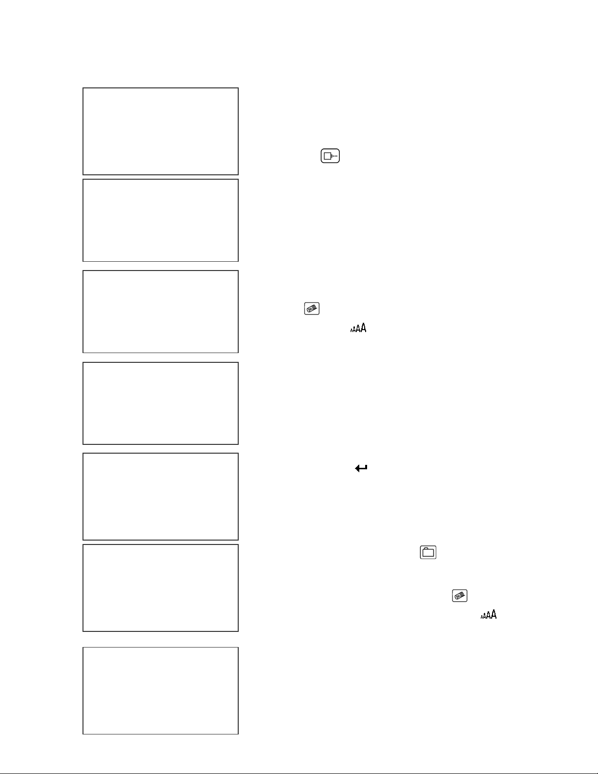
ENTERING A MIXED RASTER PREFIX
$
LX x STOPPED
HD1- - >SPEED=100
EVOLU
PREFIX ENTRY
- - - - FONT- 1 LINE
PREFIX ENTRY
- - - - FONT- 1 LINE
PREFIX ENTRY
- - - - FONT- 1 LINE
12
LX x STOPPED
HD1- - >SPEED=100
EVOLU
MESSAGE ENTRY
- - - - FONT- 1 LINE
Entering a mixed raster message requires a twostep process. The simplest approach is to first
create the prefix.
If the printer is in the PRINTING mode press the
stop print key . The LCD should be as pictured
on the left.
Press the S1 key on the keyboard, which enters
the PREFIX ENTRY mode. At this point message
entry is identical to the normal MESSAGE ENTRY
mode.
The lower half of the LCD may or may not contain
data. If data is present press the F3 key or use the
delete key to clear the current data.
Press the font key to select either a 1-line or
2-line prefix and enter the desired data.
Remember that the data may be any legal data
entry as available in the normal MESSAGE
ENTRY mode.
Following font size selection enter the desired
message. In the pictorial at the left the message
prefix $12 was entered. Remember the special
symbols are found by pressing the S1 key.
Press the enter key to return to the STOPPED
mode.
The next step in mixed raster messages is to enter
the remainder of the message.
Press the message entry key to enter the
MESSAGE ENTRY mode.
Press the F3 key or use the delete key to clear
the current data. And use the font key
select the font size required for the rest of the
message.
MESSAGE ENTRY
- - - - FONT- 2 LINE
Enter the 2 lines of data required for the
message.
.95
BEST BY
38 EVOLUTION LX SYSTEM MANUAL Issue 1.0 5 DEC 2009
to
Page 56
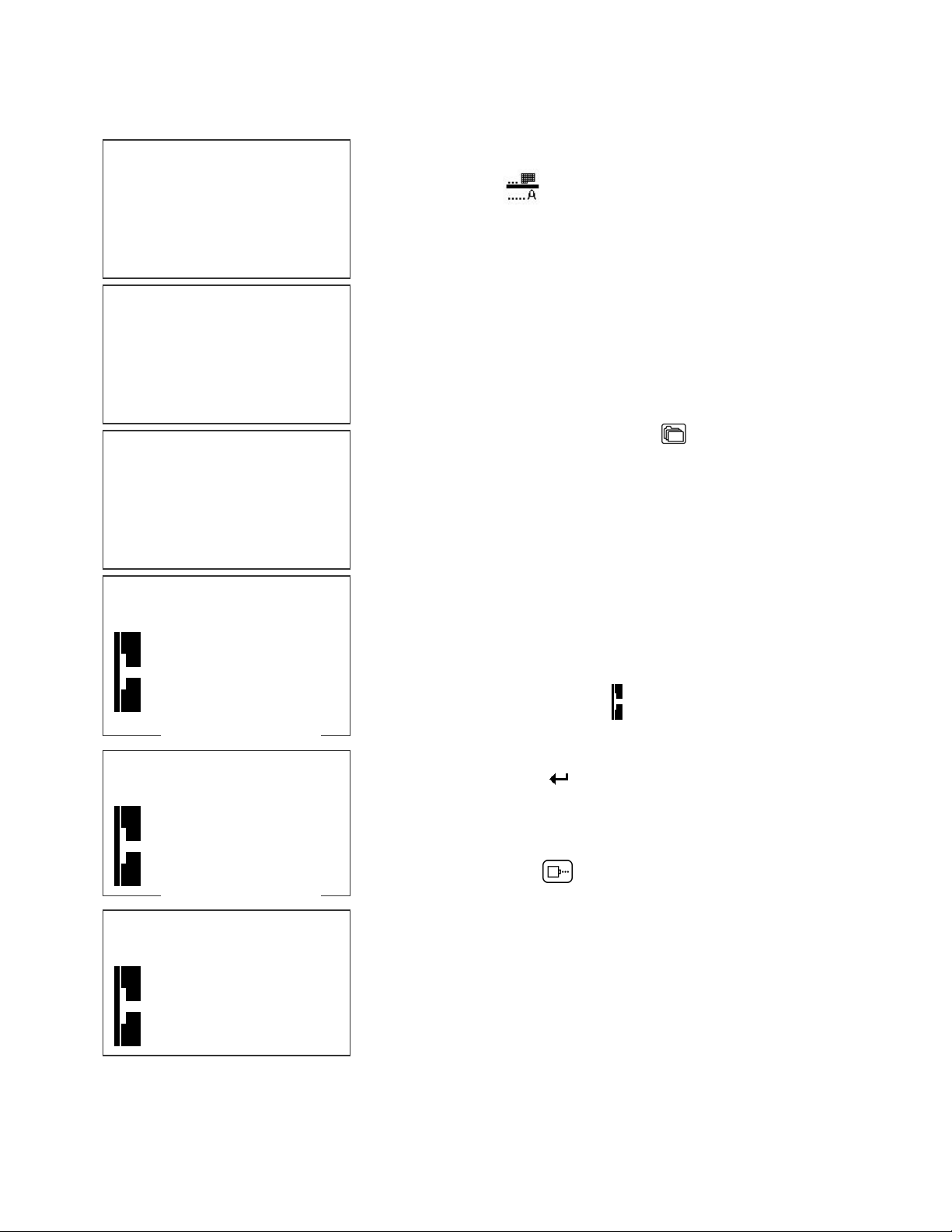
The example below shows a 2-line message. The top line of the message is the
balance of the price .95 and the second line of the
MESSAGE ENTRY
- - - - FONT- 2 LINE
BY 19
MESSAGE ENTRY
- - - - FONT- 2 LINE
MAY
.95
BEST BY 19
MESSAGE ENTRY
- - - - FONT- 2 LINE
BY 19
MESSAGE ENTRY
- - - - FONT- 2 LINE
MAY
message are the words BEST BY followed by the
expiration date key. Remember that variable
field data must be entered using the appropriate
special function key.
NOTE: That the beginning of the message is not
shown because as data is entered on the second line
the actual message caused the message area to
scroll left out of view.
Press the F1 key to redisplay the message from the
beginning.
The prefix data may now be entered into the
message. DO NOT EXIT MESSAGE ENTRY MODE.
Press the message storage key . While in the
MESSAGE ENTRY mode. The message storage key
has a different function in this mode and does not
save the message to storage, but rather enters the
prefix message previously created.
The prefix message is entered but because the
message was longer than the display area the display
scrolled to the left.
Press the F1 key to display the message from the
beginning.
The prefix message is now displayed at the beginning
BEST BY
LX x STOPPED
HD1- - >SPEED=100
BEST BY
LX x PRINTING
HD1- - >SPEED=100
BEST BY
of the message shown as the symbol.
Press the enter key
mode.
The message is ready for printing.
Press the print key to place the printer in the
PRINTING mode.
The message may be stored by selecting the
message storage option.
NOTE: changing a prefix after a message
is created will automatically update the
current message with the new prefix.
to return to the STOPPED
39 EVOLUTION LX SYSTEM MANUAL Issue 1.0 5 DEC 2009
Page 57
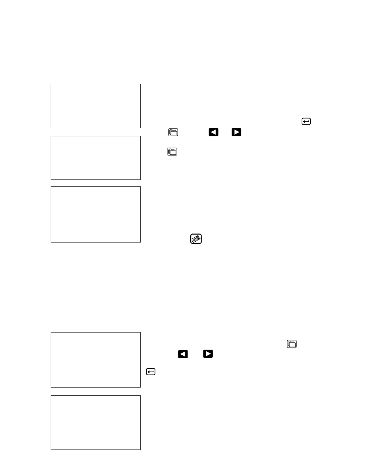
MESSAGE STORAGE (LX1 WITH OP 1, 1.5,2,3 OR LX 2)
STORING A MESSAGE
All LX printers are able to store up to 100
MESSAGE # 1
MESSAGE # 1
PLEASE WAIT
MESSAGE # 1
MESSAGE STORED
(depending on options and or model types) system
wide programmed messages and their associated
parameters. Follow these steps to store a
message. Create the message and press .
Press . Using or , scroll to the desired
message location number.
Press a second time. This places the message
into that numeric location for recall at a later time.
Use the same procedure to overwrite an existing
stored message as well.
Stored messages are system dependent and can
not be loaded into other system types. For example
a message created for an LX 2 can not be sent to
an LX 1.
The LCD display will indicate that the message is
EVOLU
stored. Press to exit.
NOTE: Message storage should be used after the product has been coded
satisfactorily. When a message is stored all operating parameters of the
printed code are saved. Once recalled, codes will be printed the same as
they had been before.
Option pack 1 enables the user to store up to 50 messages in the hand held
controller. With option pack 1.5, 2, 3 or LX 2 the controller is capable of
storing up to 100 messages.
RECALLING A STORED MESSAGE
MESSAGE # 1
EVOLU
LX x STOPPED
HD1- - >SPEED=120
Place the unit in “Stopped” mode and press .
Use the or to scroll through the stored
messages. Find the desired message and press
. That message is now displayed on the screen
ready for printing.
EVOLU
40 EVOLUTION LX SYSTEM MANUAL Issue 1.0 5 DEC 2009
Page 58
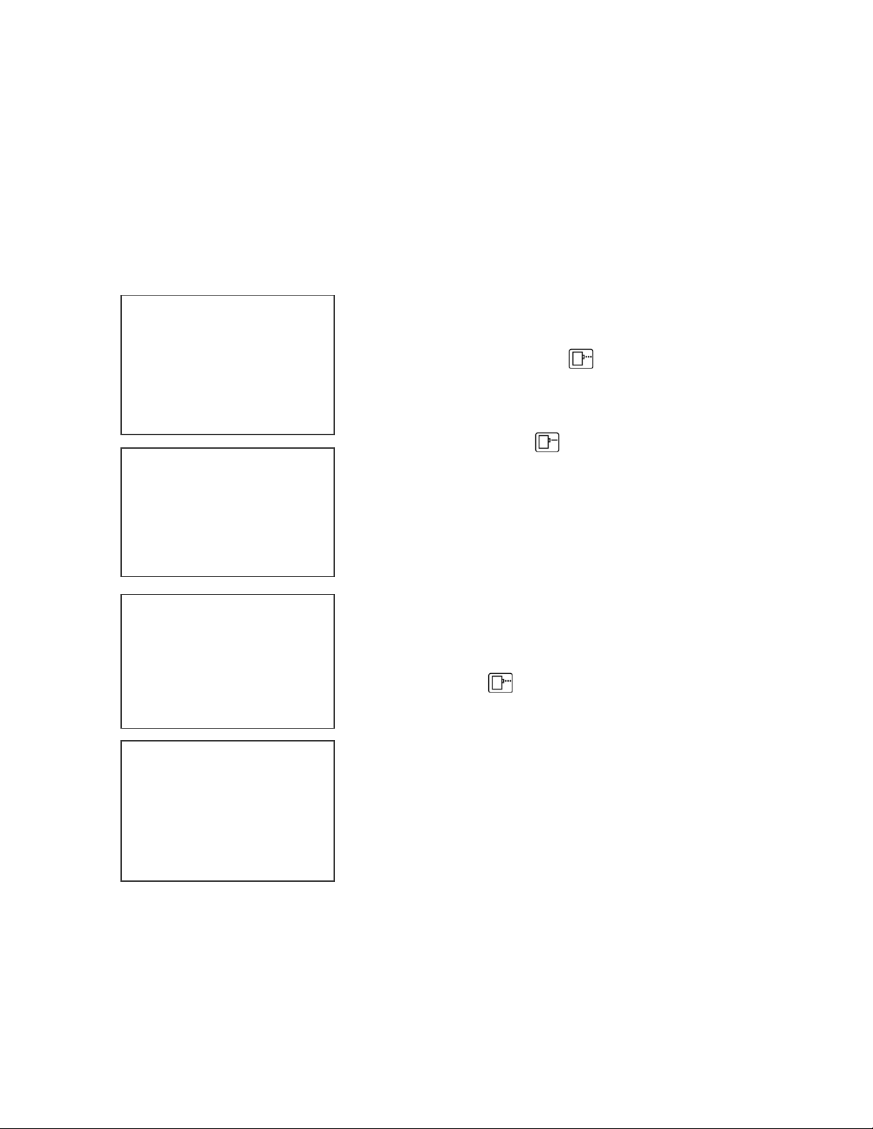
PART 3: MAINTENANCE PROCEDURES
PERIODS OF SHUT DOWN
SHORT PERIODS OF SHUT DOWN
When the printer has been shut down overnight, the system might require a
purge to clear out dust particles that have settled on the nozzle area during nonuse. This is only necessary if there are missing dots in the printed code on
product. NOTE: IT IS BEST TO REMOVE CARTRIDGES WHEN NOT IN USE,
AND STORED IN THE APPROVED CARTRIDGE CLIP.
LX x STOPPED
HD1- - >SPEED=100
EVOLU
PURGING
LX x STOPPED
HD1- - >SPEED=100
To purge be sure that the unit is in the STOPPED
Mode by pressing green key. The screen
changes to STOPPED as shown to left.
Place a piece of lint free wipe in front of the print
head and press the red . Allow the unit to purge
for several seconds. There is an automatic shut
down after 1,000 printed columns to ensure that the
print head will not be damaged. If ink residue has
solidified on the nozzle area a small drop of ink may
be applied to the lint free wipe.
When purging is complete the LCD will be returned
to the STOPPED Mode.
Press the green and the screen changes to
EVOLU
LX x PRINTING
HD1- - >SPEED=100
PRINTING, as shown at the left. The unit is ready
to begin coding.
EVOLU
1 EVOLUTION LX SYSTEM MANUAL Issue 1.0 5 DEC 2009
Page 59
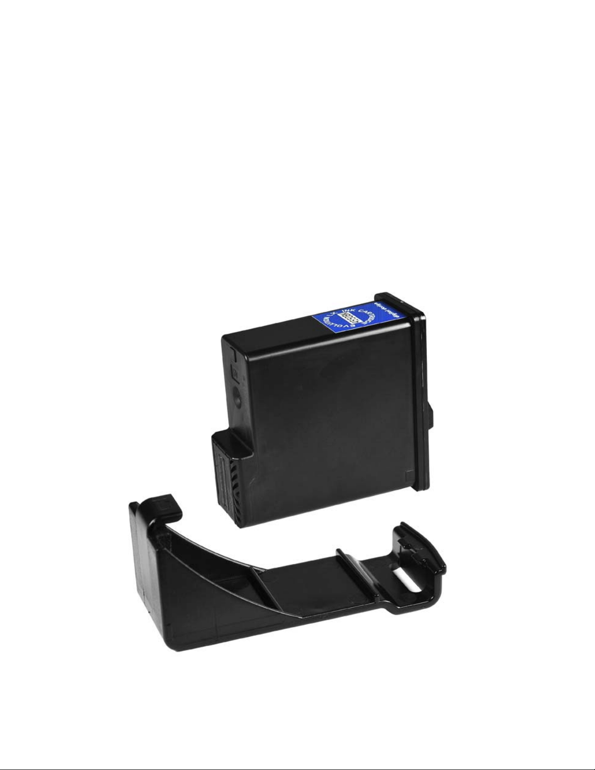
LONG PERIODS OF SHUT-DOWN
When the printer is to be shut down for extended periods, or the ink cartridge
needs to be changed to insert a different color cartridge, the ink cartridge should
be removed.
Clean the print head nozzle area with a soft, lint free wipe and insure there is no
ink residue remaining on the nozzle area. The print cartridge should be stored in
the approved cartridge clip (4X50-CLIP).
CAUTION: DO NOT USE THE ORIGINAL SEALING TAPE
SUPPLIED WITH THE
EVOLUTION LX INK CARTRIDGE AS IT MAY
HAVE BEEN CONTAMINATED. DO NOT USE ANY OTHER
MATERIAL OR ANY ADHESIVE BACKED PRODUCT, AS THIS
WILL DAMAGE THE NOZZLE AREA.
2 EVOLUTION LX SYSTEM MANUAL Issue 1.0 5 DEC 2009
Page 60
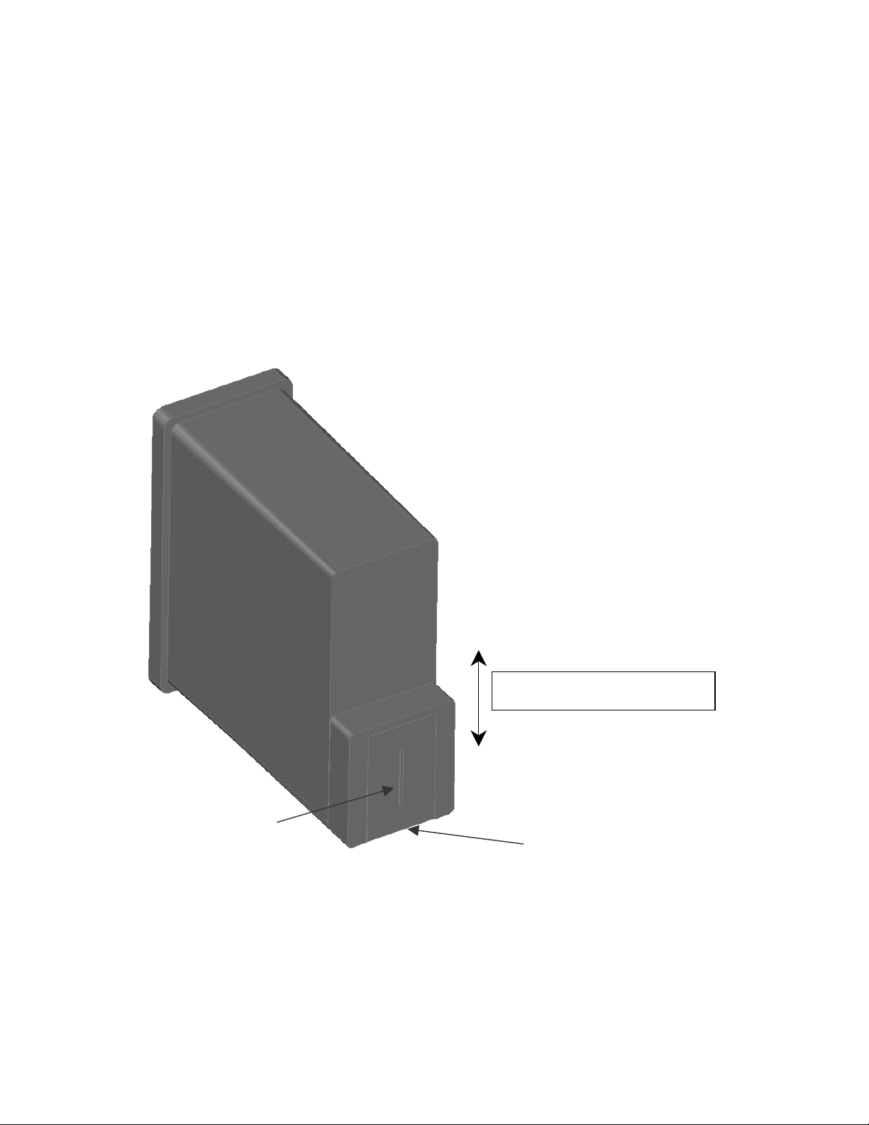
PRINT CARTRIDGE MAINTENANCE
It is necessary to maintain the EVOLUTION print cartridge free from accumulated
dust and debris. Periodically the cartridge should be removed and cleaned. This
is totally dependent on the operating environment and the average printable life
of the ink cartridge. In extremely dusty environments, this maintenance
procedure may be required regularly.
To clean the cartridge, carefully clean the face of the cartridge with a soft, lint
free wipe. Use caution in wiping the NOZZLE area so as not to scratch the face.
Always wipe in the ARRAY PLATE vertically as indicated.
Clean the CONTACT area in a similar fashion.
DIRECTION OF WIPING
NOZZLES
CONTACT AREA
3 EVOLUTION LX SYSTEM MANUAL Issue 1.0 5 DEC 2009
Page 61
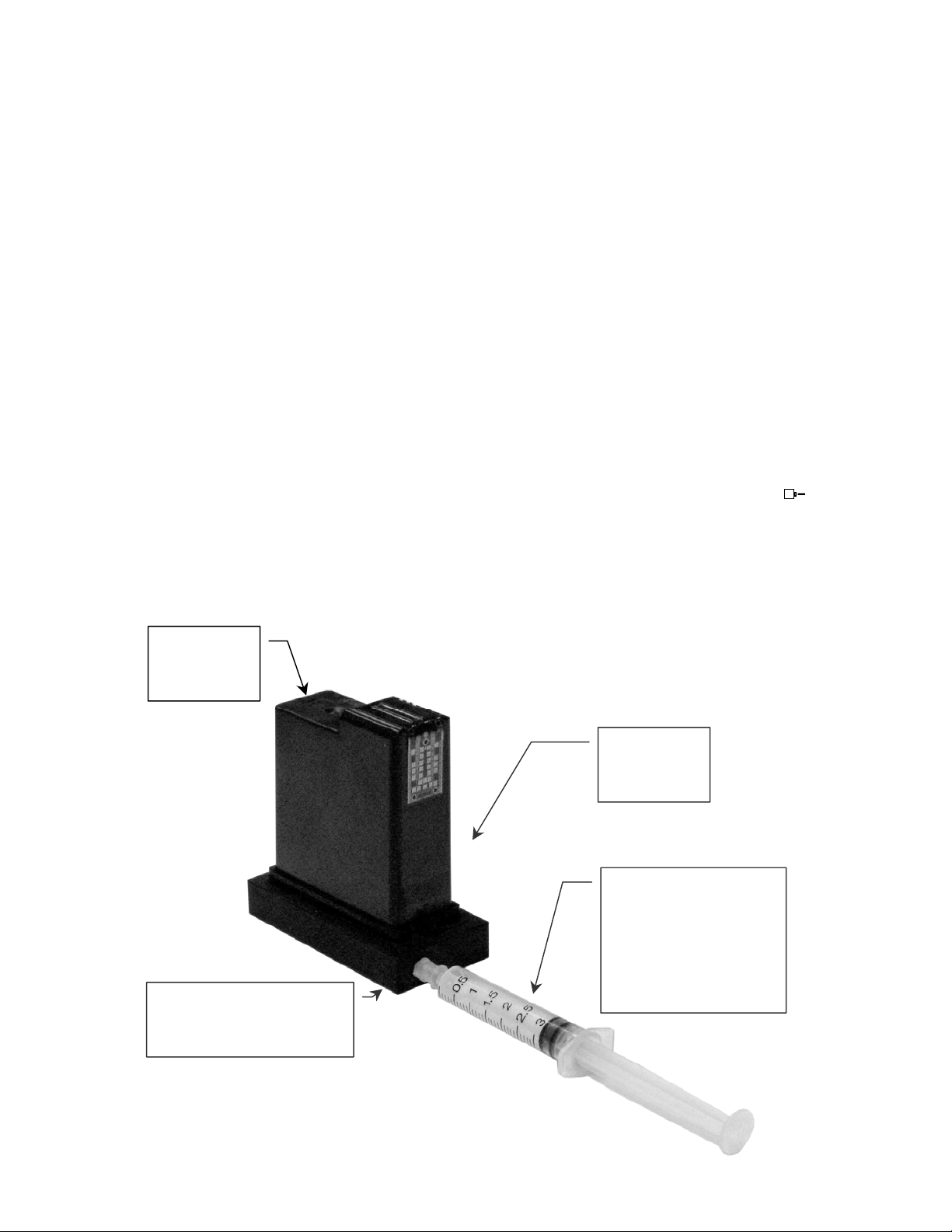
CLEANING TRAY 4X50-CLEAN (ORDERED SEPARATELY)
p
y
NOTE:
Ingested air or severe nozzle clogs may be eliminated with the
use of the cleaning syringe/tray ordered optionally.
The photo below shows the correct procedure in using the syringe and cleaning
tray. Place the tip of the syringe (optional pump) into the front of the tray’s luer
lock connector. Place the ink cartridge onto the tray and apply a downward
pressure ensuring that the cartridge is securely pressed against the rubber
gasket in the tray. While holding the cartridge securely in place gently apply
pressure to the syringe plunger until ink flows from the nozzle area. NOTE: Never
draw back on the syringe, as this will ingest air into the cartridge causing a loss
of prime. Repeat this procedure several times while watching the ink flow.
Between each cycle gently remove the standing ink on the nozzle area with a lint
free wipe. Following ink evacuation remove the cartridge from the tray. Remove
any remaining ink from the nozzle face with a lint free wipe. Replace the cartridge
into the printer. Place a piece of clean white paper directly in front of the print
head and perform a purge function by pressing and releasing the purge key .
The key is activated on the release of the key. Swipe the paper quickly past the
print head to expand the purge pattern so the individual droplets may be viewed.
Perform a test print and verify that all nozzles are firing correctly.
NOTE: An optional air pump 4x50-PUMP may be purchased separately for
easier operation.
Apply
downward
ressure
Cleaning/Priming
Tray
4x50-CLEAN
Place
Cartridge
on tra
Apply pressure to
plunger on syringe
Never draw back
on plunger while
cartridge is
seated in tray
4 EVOLUTION LX SYSTEM MANUAL Issue 1.0 5 DEC 2009
Page 62
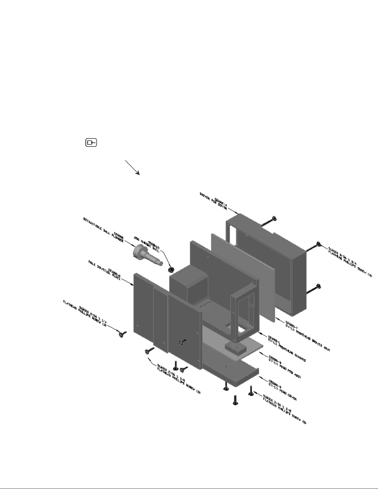
PRINTER MAINTENANCE
It is necessary to maintain the printer free from accumulated dust and debris.
Periodically the printer should be inspected and cleaned. This is totally
dependent on the operating environment. In extremely dusty environments, this
maintenance procedure may be required occasionally but on average every
week should be sufficient.
Remove the print cartridge and carefully inspect the printer for ink, dust and
debris.
Re-insert the print cartridge and place the unit into the PRINTING mode by
pressing .
CLEANING/PRIMING
TRAY
4X50-CLEAN
EXPLODED VIEW OF THE PRINT HEAD CHASSIS
5 EVOLUTION LX SYSTEM MANUAL Issue 1.0 5 DEC 2009
Page 63
PRINTER ADDED FEATURES
The LX series of printers have an added feature not found in the normal HP
based Evolution products. To understand these features a brief description is
required.
The HP style print head contains two columns, each containing 150 nozzles in
the vertical direction. The spacing between the two columns is approximately
0.140” (3.56mm). The EV products use only one column, and inks have been
developed to provide an optical density at 300 DPI comparable to lesser quality
inks requiring printing at 600 DPI. Printing at 600 DPI also requires an encoder to
accurately overlay both columns.
The LX style print head has the unique feature of containing 4 columns that are
selectable under software control. The columns are arranged such that columns
1 and 2 and columns 3 and 4 are separated by 0.00083” (0.021mm). There is a
gap between the first 2 columns and the second set of two columns. This gap is
approximately 0.040” (1mm).
Since the cartridge is software controllable, the user has the option of selecting
which column or columns are to be used. It is therefore possible to fire columns 1
& 2 or columns 3 & 4. The result is a 600 DPI print without an encoder.
While in the STOPPED Mode pressing the F1 function key followed by the C key,
the user may select the column or columns to print with as follows:
< - - SELECT - - >
HEAD COLUMN= 1
1 = column 1 300 DPI
2 = column 2 300 DPI
3 = column 3 300 DPI
4 = column 4 300 DPI
5 = columns 1 & 2 BOLD PRINT 600 DPI
6 = columns 3 & 4 BOLD PRINT 600 DPI
7 = column 1, 2, 3, 4 automatically changing each print cycle at 300 DPI
8 = column 1&2, 3&4 automatically changing each print cycle at 600 DPI
Features 7 and 8 are special functions that are intended to circumvent inherent
problems encountered with the HP style cartridges. For example, when printing a
small character with the HP cartridge, individual firing resistors may become
ineffective before the ink in the cartridge is exhausted. Using option 7
automatically prints the message sequencing the 4 columns in the LX cartridge.
This ensures the ink in the LX cartridge is fully used without the necessity of
altering the message location to a different line as in HP units.
Those applications requiring a bolder print can use either option 5 or 6, or use
option 8 for auto sequencing.
In either 7 or 8 there will be a small gap between the start of each message.
The system default is column 1 and may be
changed by using the arrow keys. Notice
that the numbers 1 to 8 are selectable. Each
number represents a different column or
combinatorial.
6 EVOLUTION LX SYSTEM MANUAL Issue 1.0 5 DEC 2009
Page 64
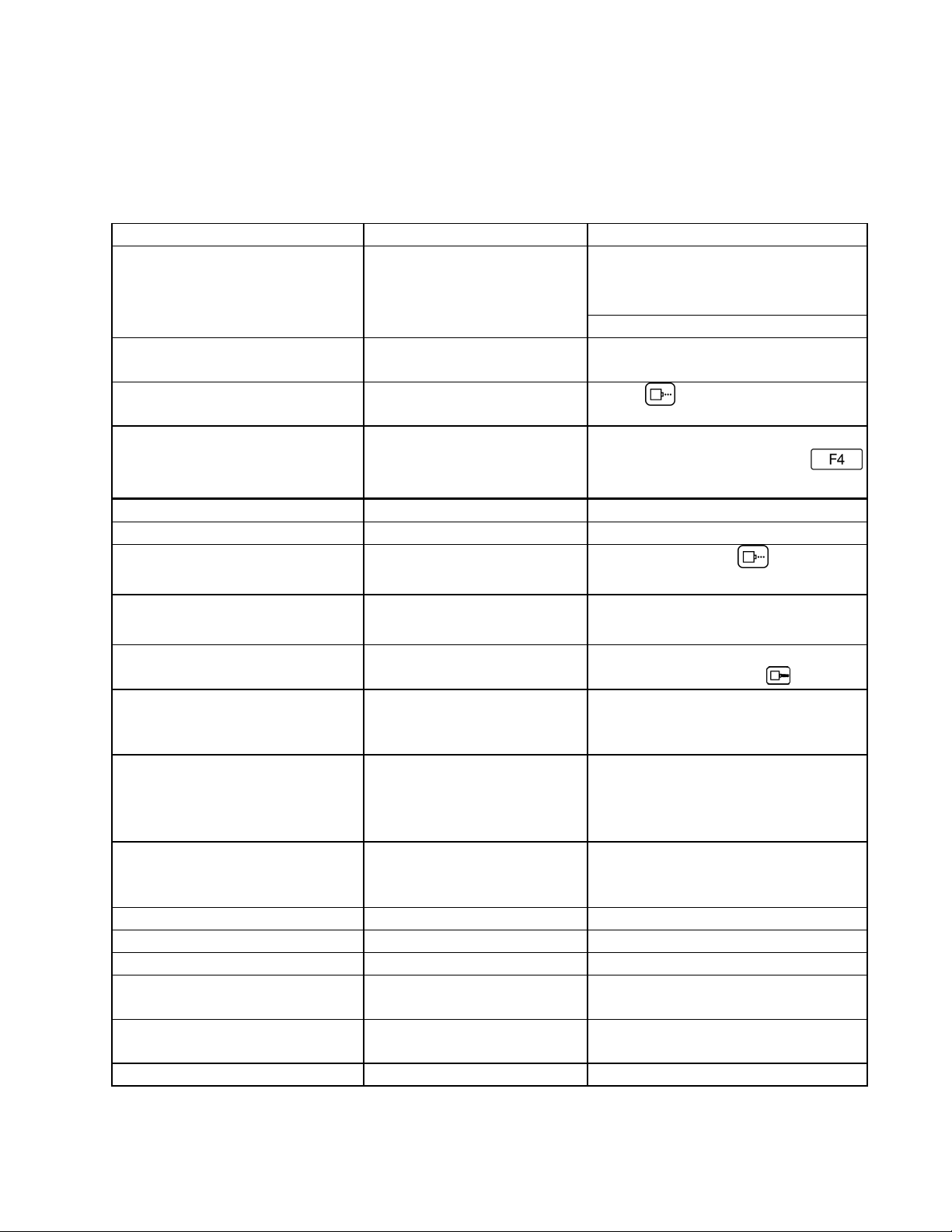
PART 4: TROUBLESHOOTING AND REPAIRS
A
This chart was created to assist the user in troubleshooting the unit. Find the
problem in the first column; apply the remedy(s) suggested in the third column.
Condition Probable Cause Remedy
LCD remains blank. No power.
Unit does not print, although
LCD shows information.
Unit in “STOPPED”
Unit does not purge. Out of ink. Replace with new ink cartridge.
Unit in “PRINTING” mode
No message in unit Input your message (see pages
mode.
No ink. Replace ink cartridge; reset ink
Ensure the controller is securely
connected to the correct port on
the printer assembly
2-26).
Press
volume parameter (press
and follow the sequence.
Press Stop Print.
.
Ink cartridge clogged Clean Ink Cartridge Nozzle area
with lint free wipe
Missing one or more dots
from code.
Long down-time. Follow daily start-up procedure if
Unit loses data while printing Static electricity Eliminate source of static.
High levels of radio
Spikes in electrical line. Use AC line filter
Cartridge Invalid Non DDI cartridge Replace with approved cartridge
Improper installation Re install cartridge
No Response Improperly seated
Multiple heads with the
Spikes in electrical line. Use AC line filter
No ink. Clean or Replace cartridge and
purge system (press ).
your line experienced a long
down time.
ttach ground strap between
print head and low impedance
earth ground.
Move unit to an alternate
frequency.
connection
same address
location or attach ground strap
as above.
Reseat connectors or corroded
pins
Readdress the heads correctly
1 EVOLUTION LX SYSTEM MANUAL Issue 1.0 5 DEC 2009
Page 65

PART 5: PARTS LIST AND OPTIONS
Part No. Description
C21001-1
SPARE PARTS
EVOLUTION Controller Cabinet
C21030-2
C21030-1
C30238
C22001
C22007
C22001-7
C22001-8
C21005
C21000-2
96280-01 Floor stand
EV1-BOX Spring Loaded Carton Follower
EV1-TMT Top Coding Mounting Bracket
C21050 Low Ink Warning Beacon
C21010-5 Articulating Flex Mount Bracket
C21006 External Product Detect
C21007 External Encoder
EVOLUTION Controller LCD Assembly
EVOLUTION Controller PCB Assembly
EVOLUTION Controller Keypad
EVOLUTION LX 1 Printer Assembly
EVOLUTION LX 2 Printer Assembly
EVOLUTION LX Printer CPU Assembly
EVOLUTION LX Head POGO Assembly
EVOLUTION LX Mounting Bracket Assembly
EVOLUTION Power supply
OPTIONS
C21012 Optional Junction Box
EV1-SW1 Option Pack 1 Password, 50 - Message Store, Auto Repeat
EV1-SW1.5 Option Pack 1.5 Expanded Message Length, 100 - Message storage
EV1-SW2 Option Pack 2 (Option Pack 1 & 1.5) & Time, Date, Sequential Number
EV1-SW3 Option Pack 3 (Option Pack 2) & Date Offset, Shift Code, Product Count
EV1-FONT Alternate Font (Specify when ordering)
EV1-LOGO Logo Option (Specify when ordering)
4X50-CLIP Lexmark Cartridge Clip
4x50-CLEAN Lexmark Cleaning/Priming Tray With Syringe
4x50-PUMP Lexmark Cleaning/Priming Tray Pump
EVOLUTION LX SYSTEM MANUAL Issue 1.0 5 DEC 2009 1
Page 66

C21008-1
C21008-3
C21008-10
CABLES
EVOLUTION LX RJ50 Cable 7 INCH
EVOLUTION LX RJ50 Cable 3 Feet
EVOLUTION LX RJ50 Cable 10 Feet
C21008-25
C21008-50
C21008-100
EVOLUTION LX RJ50 Cable 25 Feet
EVOLUTION LX RJ50 Cable 50 Feet
EVOLUTION LX RJ50 Cable 100 Feet
INKS
4550BK6 6 Pack of Black Ink Cartridges
4550RD6 6 Pack of Red Ink Cartridges
4550GR6 6 Pack of Green Ink Cartridges
4550BL6 6 Pack of Blue Ink Cartridges
4550YW6 6 Pack of Yellow Ink Cartridges
4550CY6 6 Pack of Cyan Ink Cartridges
4550UV6 6 Pack of Ultra Violet Ink Cartridges
4650BK Black Ink Cartridges (SEMI-POROUS)
4650BL Blue Ink Cartridges (SEMI-POROUS)
4650RD Red Ink Cartridges (SEMI-POROUS)
4750BK Black Ink Cartridges (NON-POROUS)
NOTE: Digital Design is constantly developing new ink formulation to suit
the needs of our customers. The above list is a sampling of the ink
portfolio for the EVOLUTION printing systems.
EVOLUTION LX SYSTEM MANUAL Issue 1.0 5 DEC 2009 2
Page 67

PART 6: COMMUNICATIONS PROTOCOL
Introduction – Using The EVOLUTION Printer Control Language
To ensure that all features of EVOLUTION printers are used to
their fullest, this section has been written as an aid in creating
applications.
This section has been written with both the professional and
advanced programmer in mind. It is assumed the reader
understands concepts such as: ASCII codes, typical printer
control languages, command structures, objects and various
parametric programming. It is also assumed the reader can use
a programming language like C, C/C++, Basic, or any other
programming language capable of sending and receiving
commands to and from the EVOLUTION printer via a serial
communications port.
This communication protocol covers all EVOLUTION
products. Some commands are not applicable to
certain units, and care must be taken in determining
what valid commands are for each specific printer.
Commands that reference specific units are so noted.
Communications between a printer and the hand held
controller, a host computer, or PLC are identical. The
hand held controller limits the available features of the
printer to simplify operation and minimize user data
entry mistakes.
The communications protocol is via an RS485 data
link operating in a master/slave environment where
the printers are the slaves. There can only be one
master such that both the hand held controller and a
host device cannot coexist.
1 EVOLUTION LX SYSTEM MANUAL Issue 1.0 5 DEC 2009
Page 68

RS485 communications can be used effectively over
long distances (up to 1000 feet) and in electrically
noise environments as result of electromagnetic
interference from motors and welding equipment.
Also, multiple receivers (EVOLUTION Printers) -up to
32- may be connected to such a network in a linear
multi-drop configuration in a master-slave topology.
If we are interested in writing a customized Windows
software application to drive the EVOLUTION LX
printer from a personal computer the standard RS232
serial port has to be used to control and drive the
RS485 EVOLUTION LX Printer. So, the addition of a
converter from RS232 to RS485 is necessary with its
corresponding driver.
Since today the RS232 is being gradually replaced by
USB for communications in personal computers as
result of which most of the new computers desktops
and laptops no longer have built-in standard serial
(COM) ports, a USB to RS232 converter also is
necessary, therefore a “virtual serial port” which is
an emulation of the standard serial port has to be
installed. This port is created by software which
enables extra serial ports in an operating system
without additional hardware installation.
2 EVOLUTION LX SYSTEM MANUAL Issue 1.0 5 DEC 2009
Page 69

The converter its driver and the virtual serial port
along with the cables are provided by Digital Design.
Note that it assigns COM3 to the virtual serial port.
Also, in writing Windows Applications is necessary to
considerer the following:
Since, we are using the RS485 the biggest difference
related to programming the RS232 is that we can
have up to 32 EVOLUTION Printers and since
communication is initiated by a master computer
some form of arbitration is necessary therefore, the
EVOLUTION COMMUNICATIONS PROTOCOL
which is described next must be used accordingly.
Here we must make sure the first data byte to be
sent to the EVOLUTION Printer is the address of the
recipient printer, further complicating this, is the fact
that for compatibility with our legacy systems we are
using 7 bits for transmitting data(which allow us to
transmit 127 ASCII characters), so the byte that
identify the printer address has to be split up into two
nibbles(4 bits long) which means that the original
printer’s address byte has to be masked and shifted in
order to have the Upper/Lower Address nibbles which
are sent separately.
The same has to be done when a parameter (like
printer speed) is being transmitted.
3 EVOLUTION LX SYSTEM MANUAL Issue 1.0 5 DEC 2009
Page 70

Finally, if we are planning to use MS Visual Basic as
development tool for building applications we should
use the MSComm serial communications control
which allows direct control access to the standard or
virtual serial port in a PC, which of course has to be
initialized before being used, in this case also a timer
has to be used to continually pool the serial port in
order to receive data from the EVOLUTION Printer. (a
full example of it you can find in the folder:\Printer
Communications\EVCOMMTESTRELEASE\Setup.ex
e).
If, we are planning to use MS Visual C++ or MS
Visual C#, the Serial Port class included in Microsoft’s
.NET Framework is the best tool to be used (a full
example of it you can find in the folder: \Printer
Communications\EVComunications\WindowsApplicati
on14.exe).
There is also, another application to test
comunications between a PC and the EV Printer,
which is located in the folder:
\Printer Communications\Physical Connection
Test\EV_TEST.exe).
4 EVOLUTION LX SYSTEM MANUAL Issue 1.0 5 DEC 2009
Page 71

ASCII CHARACTER CHART
0 1 2 3 4 5 6 7 8 9 A B C D E F
0 NUL SOH STX ETX EOT ENQ ACK BEL BS HT LF VT FF CR SO SI
1 DLE DC1 DC2 DC3 DC4 NAK SYN ETB CAN EM SUB ESC FS GS RS US
2 SP ! " # $ % & ' ( ) * + , - . /
3 0 1 2 3 4 5 6 7 8 9 : ; < = > ?
4 @ A B C D E F G H I J K L M N O
5 P Q R S T U V W X Y Z [ \ ] ^ _
6 ` a b c d e f g h i j k l m n o
7 p q r s t u v w x y z ` | ` ~ DEL
5 EVOLUTION LX SYSTEM MANUAL Issue 1.0 5 DEC 2009
Page 72

DESCRIPTION
This communication protocol is based on Version 1.4, which was initially
released NOV 2005 and is used with all EVOLUTION products. The
communications option converses with a host computer via an RS485 data link.
NOTE: EACH REQUEST OR COMMAND SENT TO A PRINT STATION
RECEIVES A RESPONSE FROM THAT PRINT STATION. COMMUNICATIONS
SOFTWARE MUST WAIT FOR A RESPONSE TO DETERMINE IF THE PRINT
STATION WAS READY TO ACCEPT THE COMMAND, AND THE DATA WAS
VALID AND PROCESSED. NO RESPONSE COULD INDICATE THE DATA
WAS LOST. IF AN ERROR WAS DETECTED IN PROCESSING A NAK WITH
AN ERROR CODE IS RETURNED.
DATA WORD DEFINITION
Full Duplex
7 Data Bits
1 Even Parity Bit
1 Start Bit
1 Stop Bit
BAUD RATE
115,200 Bits per second
DEFINITIONS
Q=QUERY TO HEAD
R=RESPONSE FROM HEAD
D=DATA UPDATE TO HEAD
X=ACK FROM HEAD
‘!’=ASCII CHARACTER OR CHARACTERS
0x21 HEX DATA EQUIVELENT
ADDRESS= TWO ASCII REPRESENTATIONS OF HEX CHARACTERS
`x`|`y` TWO ASCII CHARACTERS REPRESENTING THE UPPER AND
LOWER
NIBBLE OF A HEXADECIMAL BYTE WHERE X IS THE UPPER
NIBBLE AND
Y IS THE LOWER NIBBLE
FOR EXAMPLE:
TO SEND A SPEED OF 105 FEET PER MINUTE SEND
ASCII : (0x3a) AND ASCII 5 (0x35)
TO SEND A DELAY OF 30 SEND
ASCII 3 (0x33) AND ASCII 0 (0x30)
NOTE: THE ` CHARACTER AND | CHARACTER ARE NOT PART OF THE DATA STREAM
AND ARE THERE FOR SEPARATION OF FIELDS ONLY.
6 EVOLUTION LX SYSTEM MANUAL Issue 1.0 5 DEC 2009
Page 73

CABLING FOR EVLINK ENVIRONMENT
C20552 RS232C to RS485 converter module
C20551 Cable from PC to RS485 converter module
C21008-xxxx Cable (define length) from EVOLUTION units to RS485 data link
C21009 Termination plug for RS485 data link
HARDWARE INTERFACE
When connecting multiple printers via an RS485 link, input and output
connectors are provided on the print station, which allows the cabling to be daisy
chained. NOTE: It is important to remember to set each of the print stations to a
unique address.
PHYSICAL CONNECTIONS RS485 PRINTER
Pin # 4 = Receive +
Pin # 5 = Receive Pin # 6 = Transmit +
Pin # 7 = Transmit Pin # 9 = Ground
Note: At the end of the data link a termination plug is installed to balance the
RS485 data link-connecting pin 4 to pin 5 and pin 6 to pin 7 with120-ohm.
PROTOCOL FORMAT:
Host request for information;
ESC|Command|SOH|EOT (Single End Host to 1 printer)
Or
ESC|STX|Address|Command|SOH|EOT (Multiple printers)
Host sending new information;
ESC|Command|Data|EOT (Single End Host to 1 printer)
Or
ESC|STX|Address|Command|Data|EOT (Multiple printers)
7 EVOLUTION LX SYSTEM MANUAL Issue 1.0 5 DEC 2009
Page 74

EVOLUTION PRINTABLE CHARACTER SET
A B C D E F G H I J K L M N O P Q R S T U V W X Y Z
0 1 2 3 4 5 6 7 8 9
Special Symbols:
ASCII Character Hexadecimal Prints As
Space (0x20) Space
! (0x21) Hour Glass
# (0x23) #
$ (0x24) $
& (0x26) &
( (0x28) (
) (0x29) )
* (0x2a) *
+ (0x2b) +
- (0x2d) . (0x2e) Period
= (0x3d) =
: (0x3a) :
/ (0x2f) /
" (0x22) Cents
% (0x25) Solid block
; (0x3b) Ň
? (0x3f) Ě
@ (0x40) Ó
Special Function Characters
` (0x7b` Large Logo 1
| (0x7c) Large Logo 2
` (0x7d` Large Logo 3
` (0x7b` Small Logo 1
| (0x7c) Small Logo 2
` (0x7d` Small Logo 3
NOTE: The same characters are used for a 2-line logo as is used for a 1-line logo. When
the message is a 1-line it accesses the logo from the font table memory map for a single
line font, which is, where the large logos are stored. Conversely when the message is a 2line then the logo is accessed from the memory map imbedded within the 2-line font table.
8 EVOLUTION LX SYSTEM MANUAL Issue 1.0 5 DEC 2009
Page 75

SOFTWARE PROTOCOL
In the following pages, all references to characters or digits pertain to the
standard ASCII character set. The bar (|) character is used as a field separator
and it is not part of the transferred data. When data is shown in hexadecimal, it
will consist of the hex number preceded by a 0x, for example (0x1B). Generally,
all packets to and from a print station begin with an ESC (0x1B) and terminate
with an EOT (0x04).
There are two types of commands:
Downloading information to the print station
Requesting information from the print station.
To distinguish the two types of commands, a SOH (0x01) is placed after the
command byte in a request command string. The following illustrates this
concept:
To download data to print station
ESC/GROUP ADDRESS/UNITADDRESS/COMMAND/DATA/EOT
To request data from the Print Station
ESC/GROUP ADDRESS/UNITADDRESS/COMMAND/SOH/EOT
NOTE: EACH REQUEST OR COMMAND SENT TO A PRINT STATION
RECEIVES A RESPONSE FROM THAT PRINT STATION. COMMUNICATIONS
SOFTWARE MUST WAIT FOR A RESPONSE TO DETERMINE IF THE PRINT
STATION WAS READY TO ACCEPT THE COMMAND, AND THE DATA WAS
VALID AND PROCESSED. NO RESPONSE COULD INDICATE THE DATA
WAS LOST OR THE PRINTER WAS OCCUPIED PERFORMING A NONINTERRUPTABLE TASK. IF AN ERROR WAS DETECTED DURING
COMMUNICATIONS A NAK WITH AN ERROR CODE IS RETURNED. IN THE
EVENT OF A NAK RESPONSE IT IS THE RESPONSIBILITY OF THE
PROGRAMMER TO DETERMINE THE NATURE OF THE ERROR, CORRECT
THE PROBLEM IF NECESSARY, AND RESEND THE COMMAND TO THE
APPROPRIATE PRINTER. IT SHOULD NEVER BE ASSUMED THAT THE
PRINTER RECEIVED THE DATA. VERIFICATION FROM THE PRINTER
SHOULD ALWAYS BE TAKEN INT CONSIDERATION.
There is often confusion concerning how data is represented when transmitted
within strings of text. As a general rule each character imbedded within a string is
an ASCII character. Take for example the command for setting the printer
address, which is the ASCII character B. The imbedded data requires two bytes
of data they are ‘X’ and ‘Y’. When received by the printer these two bytes are
concocted into an 8-bit byte. Therefore to set a printers address to 15 it is
necessary to send two ASCII characters a HEX 31 (the number 1) and a HEX 35
(the number 5)
i.e. x = 0x31 & y = 0x35 yields unit address 15
9 EVOLUTION LX SYSTEM MANUAL Issue 1.0 5 DEC 2009
Page 76

ERROR CODES
Commands to a print station, if completed successfully, return a single byte
response of an ASCII ACK (0x06). If the command was not successful, a twobyte response of an ASCII NAK (0x15) is returned, followed by an error code.
Below is a list of the returned error codes.
Both responses will be preceded with the printers address for further verification.
ACK command
ESC/GROUP ADDRESS/UNITADDRESS/ACK/EOT
NAK command
ESC/GROUP ADDRESS/UNITADDRESS/NAK/’ERROR CODE’/EOT
Where error code is a single byte ASCII 31 to 39
NAK 1 = PHYSICAL DATA ERROR
NAK 2 = ILLEGAL COMMAND BYTE
NAK 3 = MANUAL PRINT ATTEMPTED WHILE IN PRINTING MODE
NAK 4 = TRYING TO READ A WRITE ONLY FIELD
NAK 5 = TRYING TO WRITE A READ ONLY REGISTER
NAK 6 = PRINT STATION INPUT BUFFER FULL MUST PRINT BEFORE
NEXT DOWNLOAD TO CLEAR INPUT BUFFER.
NAK 7 = SYSTEM BUSY – USER HAS SYSTEM THRU KEYBOARD
NAK 8 = SYSTEM BUSY – PRINTING FUNCTION
NAK 9 = BARCODE DOES NOT VERIFY
NOTE THE FOLLOWING COMMAND SET IS APPLICABLE TO ALL
EVOLUTION MODELS EXCEPT WHERE NOTED. WHERE EV 1 OR EV 2 IS
STATED IT REFERS TO BOTH EV 1 OR EV 2 AND LX 1 OR LX 2.
10 EVOLUTION LX SYSTEM MANUAL Issue 1.0 5 DEC 2009
Page 77

COMMANDS:
'!' 0x21 Software Version (read only)
(EV 1, EV 2, EV SC)
Q. ESC|STX|Address|`!`|SOH|EOT
R. ESC|STX|Address|`PRINTER fffffssss`|CR|EOT
Where:
PRINTER= ASCII string PRINTER for EVOLUTION I LX
EV2 for EVOLUTION I LX
EVSC for EVOLUTION SC
fffff = Software and Firmware versions
(eg. 2.02H indicates version 2.02 with Firmware version H)
ssss = Optional Software loaded
Where: (for EV 1 only)
The first y indicates option pack 1 – OP1
The second y indicates option pack 2 – OP2
The third y indicates option pack 1.5 – OP1.5
The last y is reserved for option pack 3- OP 3
Where: (for EV 2 and EV SC)
Both units are standard with all options thus a ++++ will be
returned
'#' 0x23 Printer Configuration (Read only)
(EV 1, EV 2, EV SC)
Q. ESC|STX|Address|`#`|SOH|EOT
R. ESC|STX|Address|`#`|`x`|`y`|EOT
Where Byte x Bits 3,2,1,0
Bit 3 = if 1 Cartridge Not Valid
Bit 2 = Not Used
Bits 1,0 = System Type
11 = EVOLUTION I LX
10 = Evolution 2
01 = Evolution 3
00 = Evolution Small Character
Where Byte y Bits 3,2,1,0
0000 = no options available
0001 = option1 enabled
0010 = option2 enabled
0100 = option1.5 enabled
1000 = option3 enabled
'\' 0x5c Unit Serial Number (Read only 6 digits)
(EV 1, EV 2, EV SC)
Q. ESC|STX|Address|`\`|SOH|EOT
R. ESC|STX|Address|`\`|`serial number`|CR|EOT
11 EVOLUTION LX SYSTEM MANUAL Issue 1.0 5 DEC 2009
Page 78

'l' 0x6c Special Field Flags
(EV 2, EV SC AND EV 1 WITH OP1 AND ABOVE)
Q. ESC|STX|Address|`l`|SOH|EOT
R. ESC|STX|Address|`l`|`x`|`y'|EOT
Where: x defines bits 7,6,5,4
Bit 7 = don’t care
Bit 6 = dont care
Bit 5 = 1 = No guard bars
Bit 4 = 1 = Man read added to barcode
Where: y defines bits 3,2,1,0
Bit 3 = 1 = Bar checksum added to barcode
Bit 2 = 0 = Calendar will only change on 1st day of week
Bit 1 = 1 = Day of the week is alpha
Bit 0 = 1 = counting down
D. ESC|STX|Address|`l`|`x`|`y`|EOT
X. ESC|STX|Address|`l`|ACK|EOT
'8' 0x38 Control Flags
(EV 1, EV 2, EV SC)
Q. ESC|STX|Address|`8`|SOH|EOT
R. ESC|STX|Address|`8`|`x`|`y`|EOT
Where: x defines bits 7,6,5,4
Bit 7 1 = Head busy printing message
Bit 6 1 = Print image inverted
Bit 5 1 = Head busy manual cycle
Bit 4 1 = Head busy purging
Where: y defines bits 3,2,1,0
Bit 3 1 = External Encoder
Bit 2 1 = External Product Detect
Bit 1 1 = Direction forward
Bit 0 1 = Enable PRINTING Mode
D. ESC|STX|Address|`8`|`x`|`y`|EOT
X. ESC|STX|Address|`8`|ACK|EOT
Where: x defines bits 7,6,5,4
Bit 7 Don't Care
Bit 6 1 = Print image inverted
Bit 5 Don't Care
Bit 4 Don't Care
Where: y defines bits 3,2,1,0
Bit 3 1 = External Encoder
Bit 2 1 = External Product Detect
Bit 1 1 = Direction forward
Bit 0 1 = Enable PRINTING Mode
12 EVOLUTION LX SYSTEM MANUAL Issue 1.0 5 DEC 2009
Page 79

‘G’ 0x47 Errors (note: error codes must be reset)
(EV 1, EV 2, EV SC)
Q. ESC|STX|Address|`G`|SOH||EOT
R. ESC|STX|Address|`G`|'x`|`y'|EOT
Where: x defines bits 7,6,5,4
Bit 7 = UART Overrun Error
Bit 6 = Communication Overrun Error
Bit 5 = UART Framing Error
Bit 4 = UART Parity Error
Where: y defines bits 3,2,1,0
Bit 3 = Font checksum error loading from card to chip
Bit 2 = Font 1 checksum error in Ram
Bit 1 = Font 0 checksum error in Ram
Bit 0 = Real Time Clock Memory error
TO RESET ERROR CODES
D. ESC|STX|Address|`G`|'x`|`y'|EOT
same bit positions as above
use only as a mask to clear error bits.
i.e. x = 0001 and y = 0001 clears real time clock memory
error and UART parity error.
X. ESC|STX|Address|`G`|ACK|EOT
'R' 0x52 Head Status (read only)
(EV 1, EV 2, EV SC)
Q. ESC|STX|Address|`R`|SOH|EOT
R. ESC|STX|Address|`R`|`x`|`y`|EOT
Where: x defines bits 7,6,5,4
Bit 7 = Not Used
Bit 6 = Latched eye active
Bit 5 = Unfiltered eye active
Bit 4 = Product being printed
Where y defines bits 3,2,1,0
Bit 3 = auto repeat print gap active
Bit 2 = Not Used
Bit 1 = Input buffer Line 2 full
Bit 0 = Input buffer Line 1 full
13 EVOLUTION LX SYSTEM MANUAL Issue 1.0 5 DEC 2009
Page 80

'U' 0x55 General purpose flags (read only)
(EV 1, EV 2, EV SC)
Q. ESC|STX|Address|`U`|SOH|EOT
R. ESC|STX|Address|`U`|`y`|EOT
Where y defines bits 3,2,1,0
Bit 3 = Not Used
Bit 2 = Not Used
Bit 1 = Ink Cartridge Empty
Bit 0 = Mixed Raster Enabled
'B' 0x42 Set Unit Address (Write Only)
(EV 1, EV 2, EV SC)
D. ESC|STX|Address|`B`|`x`|`y`|EOT
X. ESC|STX|Address|`B`|ACK|EOT
Where x y = 8 bit unit address
i.e. x = 0x31 & y = 0x35 yields unit address 15
'1' 0x31 Auto Repeat Inter-print delay (Range 0 - 255)
(EV 2, EV SC AND EV 1 with any option pack)
Q. ESC|STX|Address|`1`|SOH|EOT
R. ESC|STX|Address|`1`|`x`|`y`|EOT
D. ESC|STX|Address|`1`|`x`|`y`|EOT
X. ESC|STX|Address|`1`|ACK|EOT
0 = Auto Repeat Disabled
Each count provides a delay equal to 16 columns for EV 1 and EV 2.
Each count provides a delay equal to 2 columns for EV SC.
'&' 0x26 Line Speed (RANGE 10-200)
(EV 1, EV 2, EV SC)
Q. ESC|STX|Address|`&`|SOH|EOT
R. ESC|STX|Address|`&`|`x`|`y`|EOT
D. ESC|STX|Address|`&`|`x`|`y`|EOT
X. ESC|STX|Address|`&`|ACK|EOT
14 EVOLUTION LX SYSTEM MANUAL Issue 1.0 5 DEC 2009
Page 81

'd' 0x64 Encoder Divider (Range 0-7)
(EV 1, EV 2, EV SC)
Q. ESC|STX|Address|`d`|SOH|EOT
R. ESC|STX|Address|`d`|`x`|`y`|EOT
D. ESC|STX|Address|`d`|`x`|`y`|EOT
X. ESC|STX|Address|`d`|ACK|EOT
'’' 0x27 Product Delay (RANGE 1-255)
(EV 1, EV 2, EV SC)
Q. ESC|STX|Address|`0x27`|SOH|EOT
R. ESC|STX|Address|`0x27`|`x`|`y`|EOT
D. ESC|STX|Address|`0x27`|`x`|`y'|EOT
X. ESC|STX|Address|`0x27`|ACK|EOT
')' 0x29 Inter-Character spaces (RANGE 1-25)
(EV 1, EV 2, EV SC)
Q. ESC|STX|Address|`)`|SOH|EOT
R. ESC|STX|Address|`)`|`x`|`y`|EOT
D. ESC|STX|Address|`)`|`x`|`y'|EOT
X. ESC|STX|Address|`)`|ACK|EOT
15 EVOLUTION LX SYSTEM MANUAL Issue 1.0 5 DEC 2009
Page 82

'>' 0x3E Head Align (Range 0 - 16) 'O' on keyboard
(EV 2 only)
Q. ESC|STX|Address|`>`|SOH|EOT
R. ESC|STX|Address|`>`|`x`|`y'|EOT
D. ESC|STX|Address|`>`|`x`|`y`|EOT
X. ESC|STX|Address|`>`|ACK|EOT
'4' 0x34 Sequence Number Rollover Value
(EV 2, EV SC AND EV 1 with version 2.09 and OP2 or 3)
Q. ESC|STX|Address|`4`|SOH|EOT
R. ESC|STX|Address|`4`|`#########`|CR|EOT
where ######### = rollover value in ascii (max 9 digits)
D. ESC|STX|Address|`4`|`#########`|CR|EOT
X. ESC|STX|Address|`4`|ACK|EOT
'^' 0x5E Lot Counter Limit Count
(EV 2, EV SC AND EV 1 with version 2.09 and OP2 or 3)
Q. ESC|STX|Address|`^`|SOH|EOT
R. ESC|STX|Address|`^`|`###`|CR|EOT
where ### = rollover value in ascii (max 4 digits)
D. ESC|STX|Address|`^`|`####`|CR|EOT
X. ESC|STX|Address|`^`|ACK|EOT
'_' 0x5F Lot Counter Value (read only)
(EV 2, EV SC AND EV 1 with version 2.09 and OP2 or 3)
Q. ESC|STX|Address|`_`|SOH|EOT
R. ESC|STX|Address|`_`|`###`|CR|EOT
where ### = current count value in ascii (max 4 digits)
D. ESC|STX|Address|`_`|`####`|CR|EOT
X. ESC|STX|Address|`_`|ACK|EOT
'[' 0x5b DATE_ROLLOVER
(EV 2, EV SC AND EV 1 with version 2.09 and OP2 or 3)
Q. ESC|STX|Address|`[`|SOH|EOT
R. ESC|STX|Address|`[`|`x`|`y`|`x1`|`y1`|EOT
Where:
|`x`|`y`| = Time of Day Hours
|`x1`|`y1`| = Time of Day Minutes
D. ESC|STX|Address|`[`|`x`|`y`|`x1`|`y1`|EOT
X. ESC|STX|Address|`[`|ACK|EOT
16 EVOLUTION LX SYSTEM MANUAL Issue 1.0 5 DEC 2009
Page 83

‘3’ 0X31 Expiration Days 1 (max 999)
or
‘@’ 0X31 Expiration Days 2 (max 999)
(EV 2, EV SC AND EV 1 WITH OP3)
Q. ESC|STX|Address|`3`|SOH|EOT
R. ESC|STX|Address|`3`|`aaaa`|EOT
Where: each set of 2 ASCII characters represent the upper and
lower nibble of a packed BCD byte
D. ESC|STX|Address|`3`|aaaa`|EOT
Where: each set of 2 ASCII characters represent the upper and
lower nibble of a packed BCD byte
X. ESC|STX|Address|`3`|ACK|EOT
'r' 0x72 Remaining Ink (0 to 99%)
(EV 1, EV 2, EV SC)
Q. ESC|STX|Address|`r` |SOH|EOT
R. ESC|STX|Address|`r`|`x`|`y`|EOT
‘0’ 0x30 Shift Code (max 6 shift codes)
(EV 2, EV SC AND EV 1 WITH OP3)
Q. ESC|STX|Address|`0`|SOH||EOT
R. ESC|STX|Address|`0`|`hh mm`|`zz`|……|CR|EOT
Where: each set of 2 ASCII characters represent the upper and
lower nibble of a packed BCD byte
…… = pattern repeat for each shift code programmed
hh = shift start hours
mm = shift start minutes
zz = shift code to print
D. ESC|STX|Address|`0`|`hhmm`|`z`|CR|EOT
Where: each set of 2 ASCII characters represent the upper and
lower nibble of a packed BCD byte
hh = shift start hours
mm = shift start minutes
zz = shift code to print
X. ESC|STX|Address|`0`|ACK|EOT
17 EVOLUTION LX SYSTEM MANUAL Issue 1.0 5 DEC 2009
Page 84

‘/’ 0x2f Product Counter (6 Digits Max)
(EV 2, EV SC AND EV 1 WITH OP3)
Q. ESC|STX|Address|`/`|SOH|EOT
R. ESC|STX|Address|`/`|`HH MM hh mm`|`cccccc`|CR|EOT
Where: each set of 2 ASCII characters represent the upper and
lower nibble of a packed BCD byte
HH = Product counter start hours
MM = Product counter start minutes
hh = Product counter stop hours
mm = Product counter stop minutes
cccccc = counter (6 Digits Max)
D. ESC|STX|Address|`/`|`ww xx yy zz`|`cccccc`|CR|EOT
Where: each set of 2 ASCII characters represent the upper and
lower nibble of a packed BCD byte
HH = Product counter start hours
MM = Product counter start minutes
hh = Product counter stop hours
mm = Product counter stop minutes
cccccc = counter
X. ESC|STX|Address|`/`|ACK|EOT
'6' 0x36 Cycle Head (Write Only)
(EV 1, EV 2, EV SC)
D. ESC|STX|Address|`6` |SOH|EOT
R. ESC|STX|Address|`6`|ACK|EOT
'`' 0x60 Print Column Configuration
(All Lexmark Models)
Q. ESC|STX|Address|```|SOH|EOT
R. ESC|STX|Address|```|`#`|CR|EOT
where 1 = Column 1
where 2 = Column 2
where 3 = Column 3
where 4 = Column 4
where 5 = Columns 1&2 (600 DPI)
where 6 = Columns 3&4 (600 DPI)
where 7 = Columns 1,2 ,3 ,4 sequencing each print cycle
where 7 = Column 1&2, 3&4 sequencing each print cycle (600 DPI)
D. ESC|STX|Address|```|`#`|CR|EOT
X. ESC|STX|Address|```|ACK|EOT
18 EVOLUTION LX SYSTEM MANUAL Issue 1.0 5 DEC 2009
Page 85

SPECIAL FIELD OBJECTS
Message Objects define special characteristics about the messages contained in
line 1 or line 2. These may define for example font size, sequence number, date
code, etc. There may be up to 15 Objects (special fields) for each line in a
message with the limitation that there can only be 1 sequence number imbedded
in a message.
'P' 0x50 Message Objects
(EV 1, EV 2, EV SC)
Q. ESC|STX|Address|`P`|SOH|aabb|EOT
R. ESC|STX|Address|`P`|`aa bb cc dd ee ff gggg hhhh`|EOT
Where: each set of 2 ASCII characters represent the upper and
lower nibble of a byte
aa = objects for which line 0 or 1
bb = number of objects transmitted. (Max 15)
Each object as defined by bb: (repeat the for each object)
cc = Position within message string
dd = Number of characters in object
ee = Attribute of the object
Where:
ee= 00 Normal Alpha/Numeric character
ee= 01 Time Hours
ee= 02 Time Minutes
ee= 03 Time Seconds
ee= 04 Date Month
ee= 05 Date Day
ee= 06 Date Year
ee= 07 Date Julian
ee= 08 Sequence Number (1 per message)
ee= 09 Barcode
ee= 0A Shift Code
ee= 0B Expiration Date Month
ee= 0C Alpha Date Code
conflict shows lot code ee= 0D Expiration Date Year
ee= 0E Expiration Date Julian
ee= 0F Expiration Date Day
ee= 10 Day of Week (1-7)
ee= 12 Expiration 2 Date Month in Alpha
ee= 13 Expiration 2 Date Year
ee= 14 Expiration 2 Date Month
ee= 15 Expiration 2 Date Julian
ee= 16 Expiration 2 Date Day
ee= 40 Valid Bar Code (EV 2 only) OR’d with other
Attributes
ee= 80 Bar Code Attribute (EV 2 only) OR’d with other
Attributes
19 EVOLUTION LX SYSTEM MANUAL Issue 1.0 5 DEC 2009
Page 86

'P' 0x50 Message Objects (continued)
ff = font of object
Where: for EV 1 AND EV 2
ff= 00 for 2 Line Font
ff= 01 for 1 Line Font
ff= 02 for 3 Line Font (EV 2 only)
ff= 03 for 4 Line Font (EV 2 only)
Where: for EVSC ONLY
ff= 00 for S5 Font
ff= 01 for S7 Font
ff= 02 for B7 Font
ff= 03 for S12 Font
ff= 04 for B12 Font
gggg = starting column of object in printed image (reserved)
hhhh = starting row of object in printed image (reserved)
D. ESC|STX|Address|`P`|`aa bb cc dd ee ff gggg hhhh`|EOT
X. ESC|STX|Address|`P`|ACK|EOT
Even though there up to 24 characters (48 characters for LX1
with OP 1.5 and above or LX 2) permitted per line data entry will
be inhibited when the 15
th
object is entered, although the last
field, if it is an alpha/numeric object, may contain enough
characters to meet the max character limit.
Barcodes are also an object field and must be considered when
entering a message. Thus a barcode with imbedded variable
field data would be counted as two or mode objects.
20 EVOLUTION LX SYSTEM MANUAL Issue 1.0 5 DEC 2009
Page 87

NOTE: PRINTER MAX CHARACTERS PER LINE
(EV 1 max 24 characters – 48 characters OP1.5, 2 or 3)
(EV 2 max 48 characters)
(EV SC max 96 characters)
'$' 0x24 Line 1 Message
Q. ESC|STX|Address|`$`|SOH|EOT
R. ESC|STX|Address|`$`|`message`|CR|EOT
D. ESC|STX|Address|`$`|`message`|CR|EOT
X. ESC|STX|Address|`$`|ACK|EOT
'%' 0x25 Line 2 Message
Q. ESC|STX|Address|`%`|SOH|EOT
R. ESC|STX|Address|`%`|`message`|CR|EOT
D. ESC|STX|Address|`%`|`message`|CR|EOT
X. ESC|STX|Address|`%`|ACK|EOT
'w' 0x77 Line 3 Message (EV 2 only max 48 characters)
Q. ESC|STX|Address|`$`|SOH|EOT
R. ESC|STX|Address|`$`|`message`|CR|EOT
D. ESC|STX|Address|`$`|`message`|CR|EOT
X. ESC|STX|Address|`$`|ACK|EOT
'z' 0x7a Line 4 Message (EV 2 only max 48 characters)
Q. ESC|STX|Address|`$`|SOH|EOT
R. ESC|STX|Address|`$`|`message`|CR|EOT
D. ESC|STX|Address|`$`|`message`|CR|EOT
X. ESC|STX|Address|`$`|ACK|EOT
'E' 0x45 Line 5 Message (Prefix line)
Q. ESC|STX|Address|`$`|SOH|EOT
R. ESC|STX|Address|`$`|`message`|CR|EOT
D. ESC|STX|Address|`$`|`message`|CR|EOT
X. ESC|STX|Address|`$`|ACK|EOT
21 EVOLUTION LX SYSTEM MANUAL Issue 1.0 5 DEC 2009
Page 88

NOTE: TO ENTER A LOGO CALLOUT INTO A MESSAGE USE
THE ACSII CHARACTERS 0x7B FOR LOGO1 0x7C FOR LOGO 2
AND 0x7D FOR LOGO 3
':' 0x3A Logo1 Name (read only - max 9 characters)
(EV 1, EV 2)
Q. ESC|STX|Address|`:`|SOH|`x`|`y`|EOT
R. ESC|STX|Address|`:`|`logo name`|CR|EOT
Where: x = don’t care
y = Bit 0 = 0 = Logo Name in Font 0
1 = Logo Name in Font 1
Bit 1 = 0 = Get Name from on board data flash chip
1 = Get Name fro Data Flash card
';' 0x3B Logo2 Name (read only - max 9 characters)
(EV 1, EV 2)
Q. ESC|STX|Address|`;`|SOH|`x`|`y`|EOT
R. ESC|STX|Address|`;`|`logo name`|CR|EOT
Where: x = don’t care
y = Bit 0 = 0 = Logo Name in Font 0
1 = Logo Name in Font 1
Bit 1 = 0 = Get Name from on board data flash chip
1 = Get Name fro Data Flash card
'<' 0x3C Logo3 Name (read only - max 9 characters)
(EV 1, EV 2)
Q. ESC|STX|Address|`<`|SOH|`x`|`y`|EOT
R. ESC|STX|Address|`<`|`logo name`|CR|EOT
Where: x = don’t care
y = Bit 0 = 0 = Logo Name in Font 0
1 = Logo Name in Font 1
Bit 1 = 0 = Get Name from on board data flash chip
1 = Get Name fro Data Flash card
'Q' 0x51 Starting Sequence Number (max. length 9 digits)
(EV 2, EV SC AND EV1 with version 2.09 and after)
Q. ESC|STX|Address|`Q`|SOH|EOT
R. ESC|STX|Address|`Q`|`zzzzzzzzz`|CR|EOT
Where:
zzzzzzzzz = ASCII string which is the starting sequence
number to print.
D. ESC|STX|Address|`Q`|`zzzzzzzzz`|CR|EOT
X. ESC|STX|Address|`Q`|ACK|EOT
22 EVOLUTION LX SYSTEM MANUAL Issue 1.0 5 DEC 2009
Page 89

'2' 0x32 Date and Time Setting / Reading
(EV 1, EV 2, EV SC)
Q. ESC|STX|Address|`2`|SOH|EOT
R. ESC|STX|Address|`2`|`aa bb cc dd ee ff gg`|EOT
Where: each set of 2 ASCII characters represent the upper and
lower nibble of a packed BCD byte
aa= Time of Day Seconds (not used)
bb= Time of Day Minutes
cc= Time of Day Hours
dd= Day of Week
ee= Date Day
ff = Date Month
gg= Date Year
D. ESC|STX|Address|`2`|`aa bb cc dd ee ff gg`|CR|EOT
X. ESC|STX|Address|`2`|ACK|EOT
'u' 0x75 Store message in non-volatile memory (Write only)
(EV 1, EV 2, and EV SC)
D. ESC|STX|Address|`u`| EOT
X. ESC|STX|Address|`u`|ACK|EOT
23 EVOLUTION LX SYSTEM MANUAL Issue 1.0 5 DEC 2009
Page 90

NOTE: THE FOLLOWING CODES ARE SPECIFIC TO EV 2
' " ' 0x22 Minimum Bar Width (Range 3-15 Data matrix 2-15)
Default 5
Q. ESC|STX|Address|`"`|SOH|EOT
R. ESC|STX|Address|`"`|`x`|`y`|EOT
D. ESC|STX|Address|`"`|`x`|`y`|EOT
X. ESC|STX|Address|`"`|ACK|EOT
' .' 0x2e Bleed Compensation (Range 0 - 3) Default 0
Q. ESC|STX|Address|`.`|SOH|EOT
R. ESC|STX|Address|`.`|`x`|`y`|EOT
D. ESC|STX|Address|`.`|`x`|`y`|EOT
X. ESC|STX|Address|`.`|ACK|EOT
' * ' 0x28 Quiet Zone (Range 0 - 150) Default 75
Q. ESC|STX|Address|`*`|SOH|EOT
R. ESC|STX|Address|`*`|`x`|`y`|EOT
D. ESC|STX|Address|`*`|`x`|`y`|EOT
X. ESC|STX|Address|`*`|ACK|EOT
'n' 0x6e Type of Barcode (read only)
Q. ESC|STX|Address|`n`|SOH|EOT
R. ESC|STX|Address|`n`|`x`|`y`|EOT
where
x = number of available barcodes
y = type of barcode
0= CODE39
1= TWO OF FIVE
2= CODE 128B
3= CODE 128C
4= UPCA
5= UPCE
6= EAN8
7= EAN13
8= DATAMATRIX
24 EVOLUTION LX SYSTEM MANUAL Issue 1.0 5 DEC 2009
Page 91

'?' 0x3F Barcode Name(read only)
Q. ESC|STX|Address|`?`|SOH|`x`|`y`|`x1`|`y1`|EOT
Where:
`x``y` = Barcode type as in 'n' command
`x1`|`y1` = don't care
R. ESC|STX|Address|`?`|`BARCODENAME`|CR|EOT
where BARCODENAME = Ascii name of type of barcode
'=' 0x3d Barcode Verify
D. ESC|STX|Address|`=`|`x`|`y`|`BARCODESTRING`|CR|EOT
x = don't care
y = type of barcode ( same as 'n' command)
BARCODESTRING = Barcode Ascii data
X. ESC|STX|Address|`=`|`xy`|EOT
where
if barcode verifies
ESC|STX|Address|`=`|ACK|EOT
if barcode doesn't verify
ESC|STX|Address|`=`|NAK|`9`|EOT
25 EVOLUTION LX SYSTEM MANUAL Issue 1.0 5 DEC 2009
Page 92

EXAMPLE WRITTEN IN C
to query a print station to determine the line speed.
INITIALIZE AND OPEN A SERIAL CHANNEL
EXECUTE THE FOLLOWING CODE
// Query Print Station Address 7 for Line Speed
putchar(0x1b); // Send out ESC
putchar(0x02); // Send out STX
putchar(0x30); // Send out upper nibble of address 07
putchar(0x37); // Send out lower nibble of address 07
putchar(0x26); // Send out a '&' command
putchar(0x01); // Send out SOH
putchar(0x04); // Send out EOT
// Get results from print station
`
unsigned char dummy,speed;
dummy = getchar(); // Get ESC
dummy = getchar(); // Get STX
dummy = getchar() << 4; // Get upper nibble of address
dummy |= getchar() & 0x0f; // Get lower nibble of address
if(dummy == our_address)
`
dummy = getchar(); // Get command
speed = getchar() << 4; // Get upper nibble of speed
speed |= getchar() & 0x0f; // Get lower nibble of speed
dummy = getchar(); // Get EOT
` else `
// error handler (not our address)
`
`
26 EVOLUTION LX SYSTEM MANUAL Issue 1.0 5 DEC 2009
Page 93

Example written in C to send a line speed to a print station
INITIALIZE AND OPEN A SERIAL CHANNEL
EXECUTE THE FOLLOWING CODE
// Send Print Head Address 2 Line Speed of 100 feet per minute.
putchar(0x1b); // Send out ESC
putchar(0x02); // Send out STX
putchar(0x30); // Send out upper nibble of address
putchar(0x32); // Send out lower nibble of address
putchar(0x26); // Send out '&' command
putchar(0x36); // Send out upper nibble for Line Speed 100
putchar(0x34); // Send out lower nibble for Line Speed 100
putchar(0x04); // Send out EOT
// Get results from print station
`
unsigned char dummy;
dummy = getchar(); // Get ESC
dummy = getchar(); // Get STX
dummy = getchar() << 4; // Get upper nibble of address
dummy |= getchar() & 0x0f; // Get lower nibble of address
if(dummy == our_address)
`
dummy = getchar(); // Get command
dummy = getchar(); // Get ACK for print station
if(!dummy == ACK)
`
// error handler (didn't get acknowledgement from printer)
` else `
dummy = getchar(); // Get EOT
`
` else `
// error handler (not our address)
`
`
27 EVOLUTION LX SYSTEM MANUAL Issue 1.0 5 DEC 2009
Page 94

EXAMPLE WRITTEN IN VB
to send a new message to a print station.
INITIALIZE AND OPEN A SERIAL CHANNEL
EXECUTE THE FOLLOWING CODE
Public Sub DoMessage()
DATA$ = "800": GETINFODATA: Rem DISABLE PRINTING MODE
DATA$ = "&32": GETINFODATA: Rem SET LINE SPEED TO 50
DATA$ = "P01010010000100000000" & Chr$(&HD): GETINFODATA: Rem SET OBJECTs
DATA$ = "%ABCDEFGHIJ" & Chr$(&HD): GETINFODATA: Rem SEND MESSAGE
End Sub
Public Sub GETINFODATA() : : Rem SENDS A COMMAND AND GETS A RESPONSE
RESPONSE$ = "": COMM.InBufferCount = 0
COMM.Output = ESC & STX & "01" & DATA$ & EOT
Timer.Enabled = True: TIMERFLAG = False
GETINFO:
Do
DoEvents
If TIMERFLAG = True Then GoTo TCOMMERROR
Loop Until COMM.InBufferCount >= 1
RESPONSE$ = RESPONSE$ & COMM.Input
If InStr(RESPONSE$, Chr$(&H15)) > 0 Then GoTo GETDATAERROR:
Rem A NAK WAS RECEIVED
If InStr(RESPONSE$, Chr$(&H4)) = 0 Then GoTo GETINFO
Rem AN EOT WAS RECEIVED
RESPONSE$ = Mid$(RESPONSE$, 6, Len(RESPONSE$))
Rem DELETE ADDRESS HEADER
Timer.Enabled = False
Rem WE NOW HAVE A VALID RESPONSE
Exit Sub
GETDATAERROR:
Timer.Enabled = False: TIMERFLAG = False
GoTo PROCESSERROR
Exit Sub
TCOMMERROR:
Timer.Enabled = False: TIMERFLAG = False
PROCESSERROR:
If RESPONSE$ = "" Then RESPONSE$ = "0" Else RESPONSE$ = Right$(RESPONSE$, 1):
Rem GET THE ERROR CODE
Select Case (RESPONSE$)
Case 0
MSG$ = "NO RESPONSE FROM UNIT"
Case 1
MSG$ = "TRANSMISSION ERROR"
Case 2
MSG$ = "ILLEGAL COMMAND"
Case 3
MSG$ = "TRYING TO PRINT WHILE IN COMMAND MODE"
Case 4
MSG$ = "TRYING TO READ A WRITE ONLY REGISTER"
Case 5
MSG$ = "TRYING TO WRITE A READ ONLY REGISTER"
Case 6
MSG$ = "UNIT INPUT BUFFER FULL"
28 EVOLUTION LX SYSTEM MANUAL Issue 1.0 5 DEC 2009
Page 95

Case 7
MSG$ = "UNIT IN EDIT MODE"
Case 8
MSG$ = "PRINT STATION BUSY TRY AGAIN"
End Select
MsgBox MSG$
COMM.InBufferCount = 0: Rem FLUSHES THE INPUT BUFFER
End Sub
THE ABOVE VB ROUTINES DEMONSTRATE THE ENTIRE SEQUENCE OF:
PREPARING DATA TO SEND TO THE HEAD
SENDING THE DATA TO THE HEAD
WAIT FOR A RESPONSE
DETERMINE IF THE DATA WAS ACCEPTED OR REJECTED
29 EVOLUTION LX SYSTEM MANUAL Issue 1.0 5 DEC 2009
Page 96
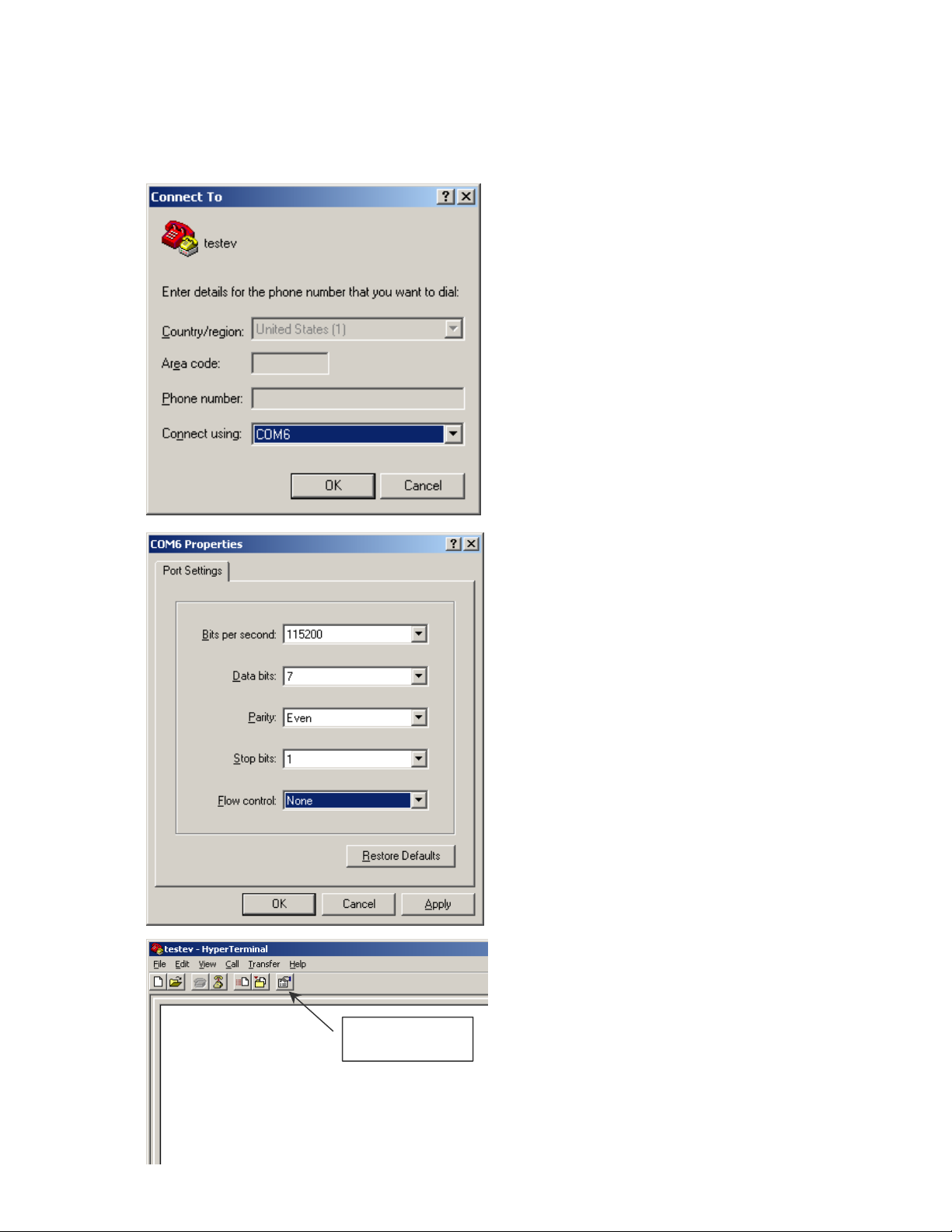
EXAMPLE USING HYPER TERMINAL
Preliminary test of the device data link can be performed using the standard
HYPER TERMINAL supplied with windows.
NOTE: it is assumed that the
user has already installed a
RS485 adapter and has
verified the device address
(COMM PORT) that device is
attached to.
Select the appropriate COM port
Set the baud rate, data bits, parity,
Stop bits and flow control.
Select properties and enter the
following settings.
PROPERTIES
30 EVOLUTION LX SYSTEM MANUAL Issue 1.0 5 DEC 2009
Page 97
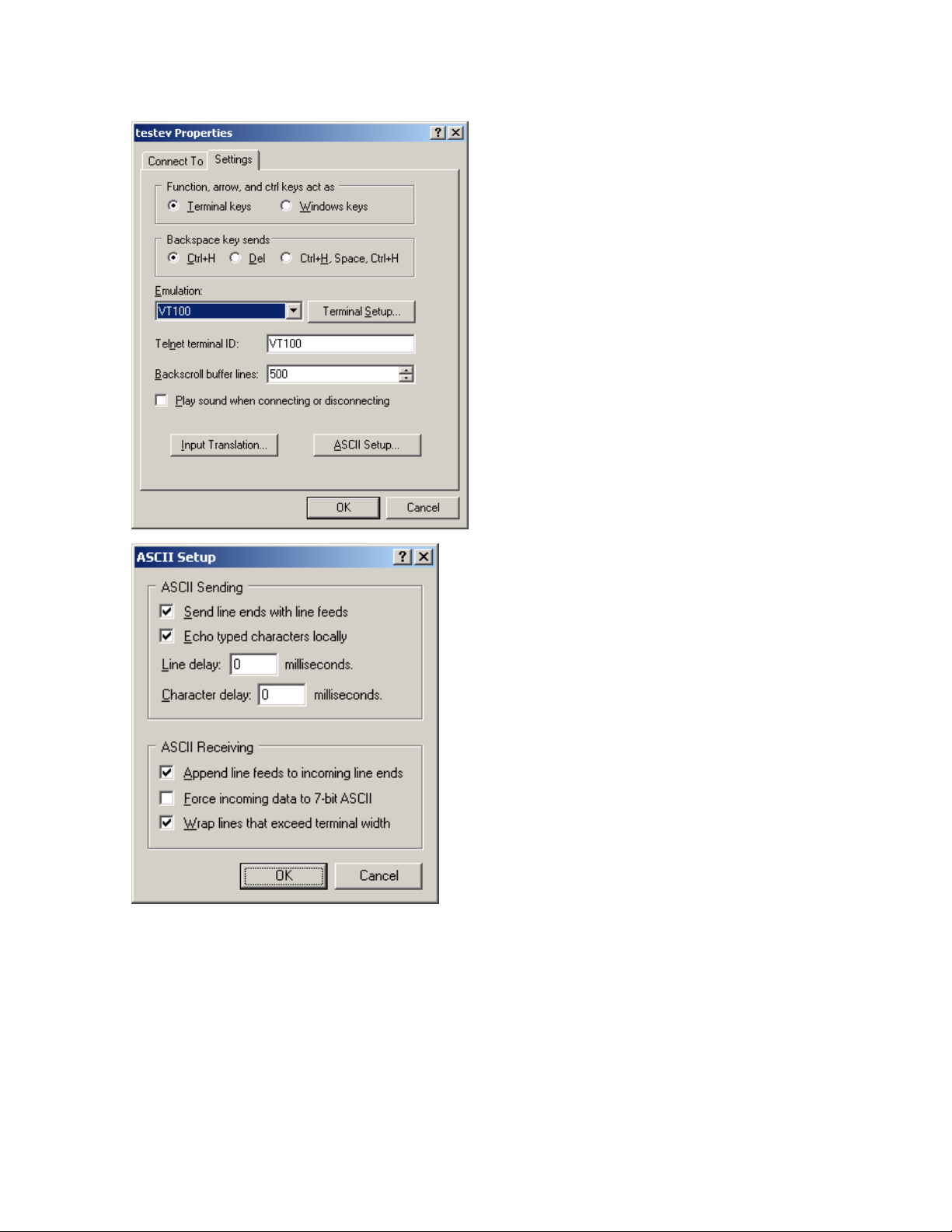
Set terminal keys checked. Select
VT100 for the emulation mode as
pictured on the left.
You can save your setup for future
usage.
There are several keys that are
required as control characters. They
are as follows:
(The ^ character represents the control
key in conjunction with the key shown)
^A THE SOH CHARACTER
^B THE STX CHARACTER
^D THE EOT CHARACTER
ESC the actual key on the keyboard
Select ASCII setup and set the appropriate
check boxes.
Test the link by typing: spaces are shown
for clarification and are not included.
ESC ^B 01 ! ^A ^D
The printer will respond with the printer’s
software/firmware information.
NOTE: NOT ALL CHARACTERS ARE
DISPLAYED ON THE SCREEN.
31 EVOLUTION LX SYSTEM MANUAL Issue 1.0 5 DEC 2009
Page 98
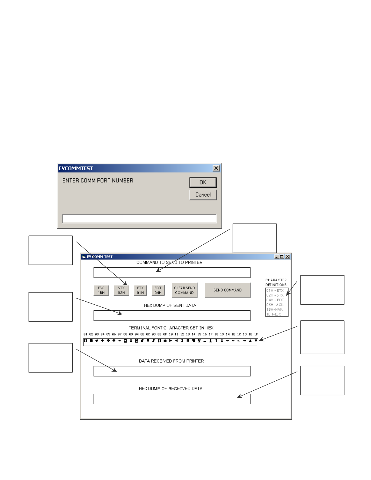
EXAMPLE USING EVCOMMTEST
Hyper Terminal has a drawback in that it does not normally display the ASCII
control character set, specifically those characters between a hex 01 through a
hex 1F. The following describes a simple program written in visual basic (VB5)
that provides the programmer with a clearer definition of the ASCII control
character sequence. The program is included on this CD manual and may be
found in the sub-directory “EVCOMMTEST”.
The user should find the correct location and install the program by invoking
“SETUP.EXE”.
NOTE: it is assumed that the user has already installed a RS485
adapter and has verified the device address (COMM PORT) that
device is attached to.
ASCII
control
characters
Hex display
of message
sent
Data
received
from printer
Enter correct COMM PORT
Program initiation displays
the COMM PORT selection
screen. The user should
enter the correct COMM
PORT and select “OK”.
Type
command
here
Character
definition
ASCII
control
character
set
Hex display
of message
received
32 EVOLUTION LX SYSTEM MANUAL Issue 1.0 5 DEC 2009
Page 99
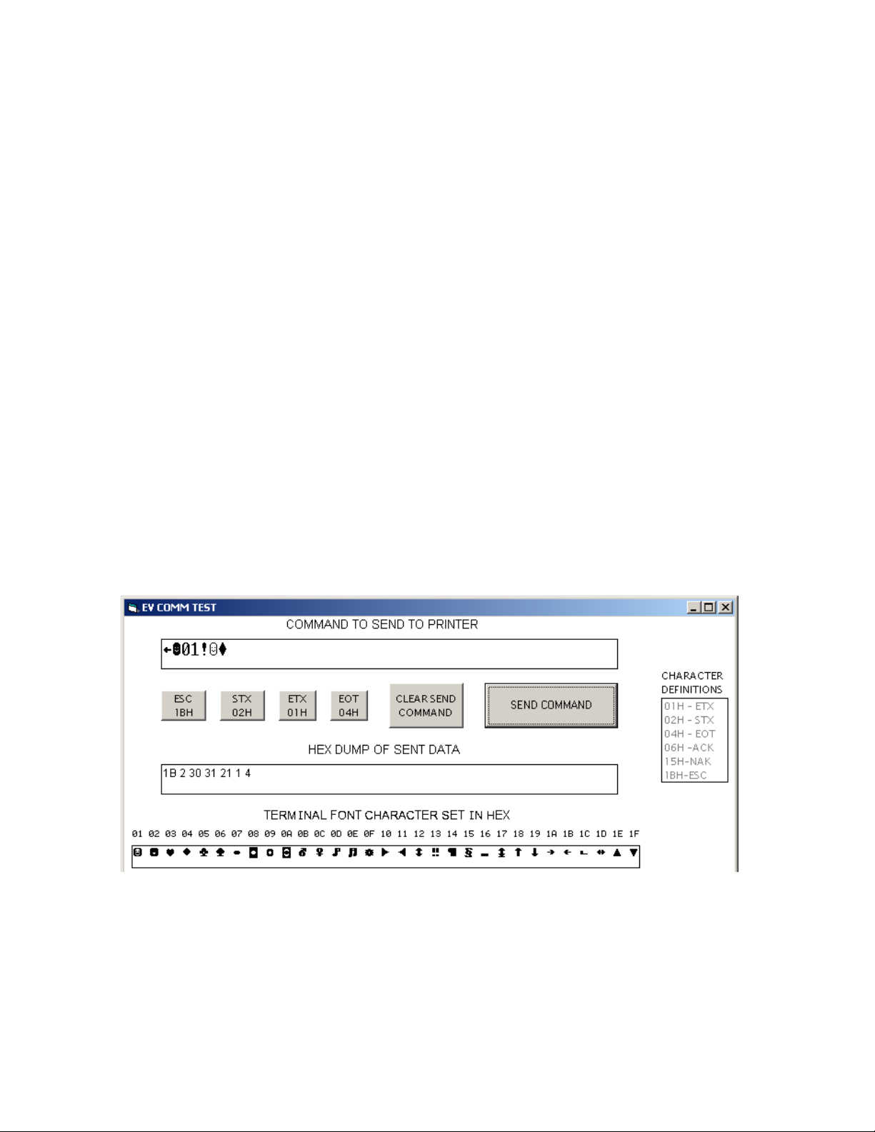
After a comm. Port is selected the above screen is displayed. This program
allows for simple command entry and provides the programmer a detailed view of
both the characters sent and the data received from the printer.
Commands to be sent to the printer are typed in first text box labeled
“COMMAND TO BE SENT TO PRINTER”. Since windows does not display
ASCII control characters, and often interprets these control characters to have
special meaning data entry for the special characters are in the form of icons on
the screen. The second line of the display shows 6 gray-scaled boxes. The first 4
boxes represent the ESC, STX, ETX and EOT ASCII control characters. The
“CLEAR SEND COMMAND’ is intended to clear the first line text box. Of course
any other windows erasing method will work. Finally the last box “SEND
COMMAND” actually sends the command typed into the first line to the printer.
To enter a command string the user must follow the correct sequence. All
command structures sent to a printer must start with the ESC character so select
the ESC gray scaled box. Next select the STX box and then place the cursor in
the command text box following the second character, which was the STX.
After the cursor is placed in the command text box it is necessary to enter the
unit ID (device address) of the printer. For initial test purposes use the factory
default setting. This default address is 01 and should be typed in the command
box following the STX. The required command follows the address. Selecting the
ETX box followed by the EOT box ends the command string. Select the “SEND
COMMAND” button to send the command to the printer.
When the “SEND COMMAND” button is selected the second text line displays
the hex values of the message sent to the printer. In this case the ASCII
character ! (Exclamation Point) was sent to the printer. This command requests
the printer to respond with the software version of the system.
For convenience the third text line displays all the ASCII control codes with the
hex values above them.
33 EVOLUTION LX SYSTEM MANUAL Issue 1.0 5 DEC 2009
Page 100
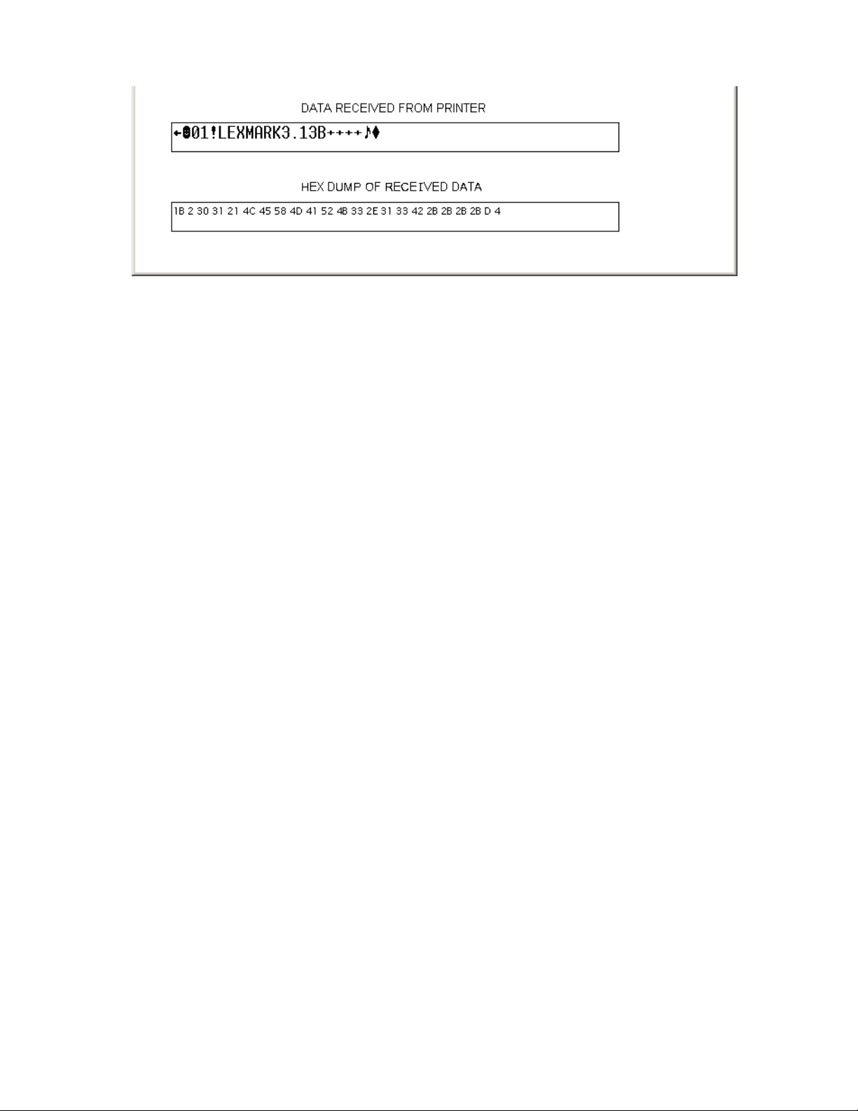
The bottom half of the display shows the ASCII data received from the printer
and the hex values for the received data displayed in the last text box.
The above response shows the printer is a LEXMARK with software version
3.13, a “B” firmware rev, and all options installed.
The programmer should try several commands to become familiar with the
typical responses received from the printer. It should also be noted that the
actual returned data might be in packed BCD format, or a hex value that needs to
be translated.
34 EVOLUTION LX SYSTEM MANUAL Issue 1.0 5 DEC 2009
 Loading...