

Page 1
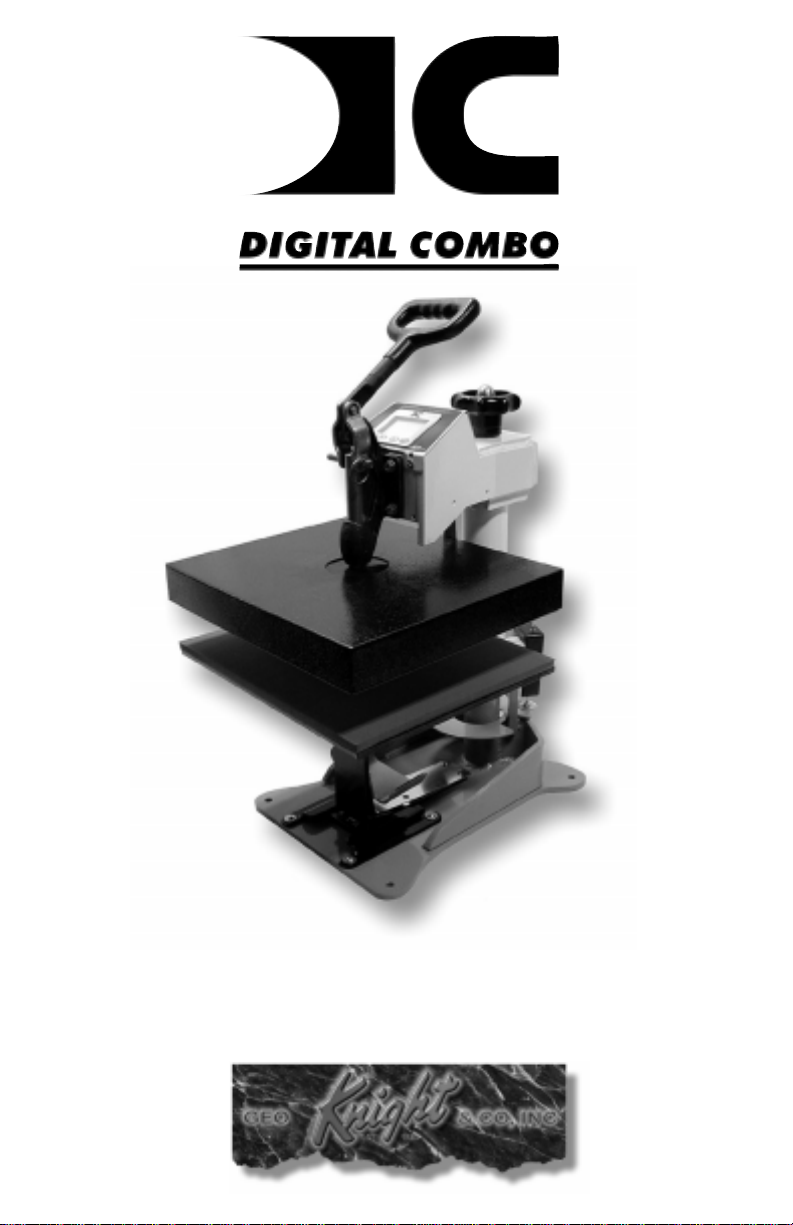
Digital Combo
Multi-Purpose press
1
Page 2

Table of Contents
T able of Contents .............................................................2
Introduction .....................................................................3
Setup & Suggestions ........................................................4
Basic Use .......................................................................... 4
Setting Time ..................................................................... 4
Setting T emperature .........................................................5
Setting Height / Pressure ..................................................6
Guidelines & Standard Settings .......................................7
Removing a heat platen....................................................8
Interchangeable Heat Platens............................................8
Attaching a heat platen ..................................................... 9
Aligning the pedestal...................................................... 1 0
Cap Holddown Device ................................................... 10
(included with cap attachment only)................................................................................................... 1 0
Interchangeable T ables................................................... 1 0
Programmable Presets.................................................... 11
User Options Menu ........................................................1 2
Fahrenheit / Celsius........................................................ 12
Timer Counter................................................................ 12
Recorded Pressings ........................................................ 12
Pressure / Height Gauge Calibration .............................. 1 3
Height Gauge - High Point ............................................. 13
Height Gauge - Low Point.............................................. 13
Pressure / Height Gauge Sensitivity ............................... 14
Drop Sense..................................................................... 14
Beep ............................................................................... 15
Alarms............................................................................ 15
Maintenance ................................................................... 16
Troubleshooting.............................................................17
Troubleshooting (cont.) ................................................. 18
Limited W arranty............................................................ 19
2
Page 3
Introduction
Congratulations on your purchase of the Digital Combo swinger!
This heat press machine has many exciting features, all of which are
meant to help make your heat transfer pressing endeavors as successful
and easy as possible. Please take the time now to thoroughly read
through this manual to become acquainted with them. It will explain
some key features, concepts and methods that will save much time
and effort in using this press and in your heat pressing applications.
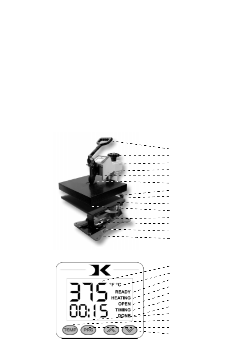
Throughout this manual, many areas and components of this
machine will be referred to by specific names. Please refer to the
illustrations below in order to become familiar with some of the
terminology used in this manual.
Handle
Pressure Knob
Top Head
Power Inlet
Clamp / Linkage
Heat Platen
Stop Collar
Height Sensor
Lower T able
Silicone Pad
Pedestal
Cap Holddown
Gibb Plates
Base
Default Operating Mode of Controller
Temperature
°Far/°Cel Indicator
Ready Indicator
Heating Indicator
Open Indicator
Timing Indicator
Done Indicator
Time
TEMP Button
PRG Button
Up/Down Arrows
3
Page 4

Setup & Suggestions
• Locate the press on a firm, sturdy work surface.
• The height of the bench/work space the press is located on would be
ideally 27” to 32” high.
• Attach the power cord from the rear to the underside of the top head.
• There is a power inlet under the top head that the modular cord will
plug into.
• Make sure the cord does no interfere with the lower table pressing
area, or the height sensor.
• The press should remain in the unclamped position when not in use.
Do not leave the heater block closed on the table surface when hot if
not using.
• The top head should be swung over and above the pressing table when
not in use.
Basic Use
Setting Time
The time setting is always editable in the default operating mode
of the controller. The left two digits of the time display are minutes.
The right two digits are seconds. This can be changed to Hours/
Minutes in the User Options Menu.
• Use the Up & Down arrow keys to change the time.
• Hold the Up or Down arrow key down to increment the values quickly.
After a brief pause, the values will accelerate.
• Press the Up & Down arrow keys together to clear the setting to 00:00
• When the press is closed, the timing cycle starts. The “TIMING”
indicator will appear.
• When the timing cycle is finished, the “DONE” indicator will appear.
• Depending on the timer alarm chosen, the alarm may continue to sound
at the end of the timing cycle until the press is opened.
• When the press is opened up, the “OPEN” indicator will appear.
4
Page 5
Setting Temperature
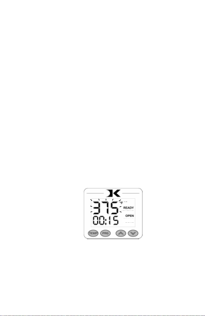
In the default operating mode of the controller, the displayed
temperature is the Current temperature. This is the actual temperature
of the heat platen surface. Please note that the operating range of the
controller is from 150°F to 550°F (65°C to 288°C). During the first
heat up cycle of the press, the controller will display 150°F (65°C)
until the heat platen temperature rises above that temperature.
The Set Point temperature is the temperature the operator sets
the press for. This is the value the press will regulate the Current
temperature based on. The set point temperature may be changed
whenever necessary:
• When in the default operating mode, press the TEMP button.
• The Current temperature will be replaced by the blinking Set Point
temperature.
• Use the Up & Down arrow keys to change the Set Point temperature.
• Hold the Up or Down arrow key down to increment the values quickly.
After a brief pause, the values will accelerate.
• Press the Up & Down arrow keys together to set the temperature to
350.
• When finished setting the temperature, press the TEMP button to return
to the default operating mode.
• The control will regulate the heat platen temperature based on the set
point temperature. When the temperature falls below the Set Point,
the “HEATING” indicator will appear.
• When the temperature reaches the Set Point, the “HEATING” indicator
will disappear and the “READY” indicator will appear.
• If the Set Point temperature is set to a temperature below the Current
temperature, the press will wait to cool down to that Set Point. At that
time, neither the “READY” or “HEATING” indicators will appear.
5
Page 6
Setting Height / Pressure
The Digital Height/Pressure gauge is a helpful indicator of the
current height of the top head as the operator adjusts the pressure.
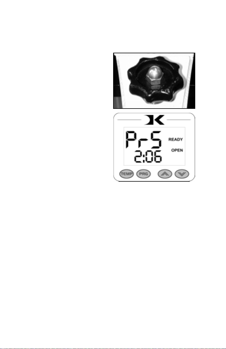
• To decrease the pressure, turn the
pressure knob to the left,
counterclockwise.
• The top head will rise away from
the lower table.
• To increase the pressure, turn the
pressure knob to the right,
clockwise.
• The top head will lower toward the
pressing table.
• If the pressure knob is turned
rapidly enough, the display will
change to the pressure gauge
display. The units of measure are
a relative scale from 0:00 to 10:00,
with :02 increments.
• To view the current pressure display value without changing it, simply
pull the pin up on the pressure gauge device on the pack post and let
it drop back down. This will force the PRS display to appear.
The gauge displays a reference value based on the height of the
heat platen in relation to the lower table. The closer the heat platen is
to the substrate on the table, the heavier the pressure. The further
away, the lighter the pressure. The amount of actual force exerted
depends on the thickness of the item being pressed and the distance
from the heat platen to the table. The digital height/pressure gauge
simply shows a relative value from 0:00 to 10:00 in fine resolution
increments as to the current height of the platen.
This helps the user return to an exact pressure setting without
the need of multiple experimentations to find the proper pressure
setting. By simply changing the pressure until the correct value
appears, previous heights and pressure settings for different thickness
substrates can be quickly reset without error.
6
Page 7

Guidelines & Standard Settings
The following information covers some basic guidelines for
pressing, as well as some generic parameters for basic heat transfer
applications.
• When pressing shirts, it is often recommended that the shirts be quickly
pressed for 2 seconds before transferring to remove wrinkles and water
content. Make sure the plate template (3 sided aluminum tray) is NOT on
the pressing table when pressing fabrics. Only the silicone pad should be
on the table.
• When pressing two sides of a garment, pull the garment over the table so
that the printed side drapes underneath the table. This will avoid reheating
previously transferred designs on opposite sides of garments. It will also
avoid any bleed-through of inks on lighter fabrics.
• Avoid laying collars, cuffs, zippers, and other bulky parts of garments on
the lower table, as these can adversely affect pressing conditions, and reduce
the life of the silicone pad.
• Always check that the transfer image is face down against the material, to
avoid sealing the image against the heat platen instead of the substrate.
• When pressing rigid substrates (plastics, metals, woods, etc.), be sure
that any protective films or laminates are removed before heating.
• When pressing tiles, and other hard inconsistent shaped materials with
beveled edges, it is often necessary to use a heat conductive pad. This heat
conductive mat is included with the Digital Combo and is only used for tile
and related surfaces, and requires an additional 35°F to be added to the
temperature. Woods, metals, and plastics usually do not require the heat
conductive rubber mat.
• When pressing plates, the plate template (3 sided aluminum tray) should
be fitted over the table to protect the silicone pad. The grey circular rubber
pad should be adhered to the center of the template to center and cushion
the plate. Use the largest green rubber circle on top of the transfer, and
press between 4-5 minutes at 435°F with firm pressure.
Always follow the transfer media suppliers instructions when pressing. The
information below is for general reference only, and may not be as accurate as the
instructions provided by the transfer media & imprintable substrate supplier.
• Hot Split Supplier Transfers 350-375°F, 8-10 secs
• Puff Transfers 350-375°, 5-7 secs (extra heavy pressure)
• Ink-Jet Transfer Papers 360°, 15-18 secs
• ColorCopy/Laser Transfer Papers 375°, 20-25 secs
• Sublimation Inks (Polyester Fabrics) 400°, 35 secs
• Sublimation Inks (Plastics) 400°, 1 min, 15 secs
• Sublimation Inks (Metals) 400°, 1 min
• Sublimation Inks (Woods) 400°, 1 min, 15 secs
• Sublimation Inks (Ceramics) 435°, 4-5 min
7
Page 8
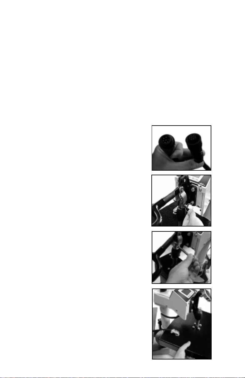
Interchangeable Heat Platens
The main feature that makes the Digital Combo so versatile is
the interchangeability of the heat platens. Because the heat platens are
modular in their method of connection, one platen can be unplugged
and another plugged in, in its place. The mechanical connection to the
clamp is no more than a simple quick release pin.
The following instructions apply to the 14x16, 12x14, cap, plate
& mug heat platen attachments. All of them disconnect and connect in
the same manner.
Removing a heat platen
• The heat platen can be safely disconnected
with the machine on. However, thermal gloves
or oven mitts must be used when handling
hot heat platens.
• Unplug the modular connector (1st figure above).
This is done by unscrewing the safety lock
and pulling the connectors apart.
• Lower the heat platen so it rests on the bottom
table, and do not clamp it.
• Pull out the quick release pin from the linkage.
It is easiest to remove when there is no
pressure on the side links or on the heat platen
shaft.
• Once the quick release pin is removed, lift the
handle away, exposing the heat platen shaft
now disconnected from the linkage.
• Lift up on the heat platen slightly , enough to
swing it out away from the bottom table.
Lower the heat platen down and out of the
clamp linkage.
8
Page 9
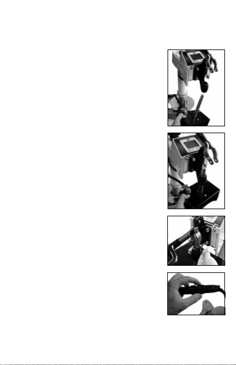
Attaching a heat platen
• The heat platen can be safely connected with
the machine on. However, thermal gloves or
oven mitts must be used when handling hot
heat platens.
• Lift the heat platen into the clamp linkage.
Make sure the rear guide fork holds onto the
guide pin in the back post of the frame. This
holds the heat platen in a straight position and
keeps it from rotating.
• Reattach the quick release pin through the
linkage and the heat platen shaft.
• Reconnect the modular connector. An Err
display might read on the controller if in the
Normal operating mode. If this is the case,
once the heat platen is reconnected, turn the
machine off and then on again.
9
Page 10
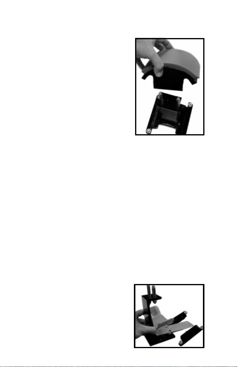
Interchangeable Tables
The lower table on the machine is
interchangeable. Different sized optional
tables can be obtained for various
materials & handling requirements.
The tables simply fit right onto the
pedestal. The 2 holes in the drop on tables
& curved forms fit onto the 2 steel pins
on the pedestal. Often times it is beneficial
to leave one of the steel pins slightly loose
to make changing out tables easier. This
will not effect evenness of pressing or
table stability.
Aligning the pedestal
The table can be easily adjusted in a straight position if the heat
platen does not correctly line up with the pressing surface. The pedestal
the table rests on can slide front to back on the base of the machine.
Loosen the screw in the gibb plates that holds the pedestal in place in
order to adjust its position.
The pedestal can also be slightly rotated in order to align with
the upper platen. Loosen all (4) screws holding the gibb plates in
place, position/rotate the pedestal to the desired place, and retighten
the gibb plates.
Cap Holddown Device
(included with cap attachment only)
There is a 1/2-moon cap holddown
device for stretching the cap over the
curved bottom table.
Simply pull the back strap of the cap
behind the pedestal and under the 1/2moon shaped bracket. This will hold the
cap in place for proper printing.
10
Page 11
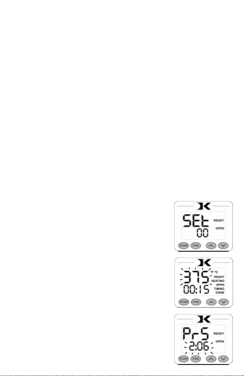
Programmable Presets
This feature is ideal for recalling previously saved settings from
various different applications. The presets are extremely easy to use,
and bring a powerful level of accuracy to heat transfer pressing.
For example, the user may have Setting 00 for Hot-Split T-Shirts.
When the user needs to perform that particular application, they simply
select Setting 00, and the Current temperature & time parameters are
updated. A pressure reference is also displayed, telling the user what
pressure to set the press to. The user can then rotate the pressure
knob until the gauge displays the same value that was stored and
displayed by the preset.
This allows the user to quickly change from one application to
another with extreme accuracy. Over time, the user will save many
different settings in the presets based on the best results for every
application. When those presets are selected, the user is immediately
returned to the proper settings, without time consuming
experimentation and risk of unsuccessful applications.
• From the default operating mode, to select a
preset, press PRG.
• Use the Up & Down arrow keys to select a preset
(00 - 70).
• Press PRG to update the current settings and return
to the default operating mode.
• To edit or add a new preset, select the preset to be
added/updated.
• Press TEMP to cycle through Temperature, Time
& Pressure values.
• The editable value will flash indicating it may be
changed.
• Use the Up & Down arrow keys to change values.
Pressing Up & Down together when editing the
temperature value resets it to 350, and 00 for time.
• After setting the pressure value, pressing PRG
again will bring the user back to the preset
selection screen.
• The user may press PRG to update the current
settings and return to the default operating mode,
or select another preset for editing/adding.
11
Page 12
User Options Menu
The user options menu is a set of features and calibration options
that are programmable and adjustable by the user. It consists of a set
of menu items that can be scrolled through. Each menu item is a
feature whose values can be viewed and /or changed. To enter the
user options menu:
• From the default operating mode, press the TEMP & PRG keys
simultaneously.
• If the keys are not pressed exactly at the same time, you may enter the
temperature edit mode, or the presets mode. Exit either of those modes
and try again.
• To cycle from one menu item to the next, press PRG.
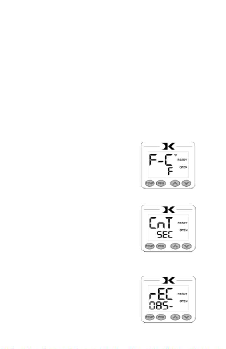
Fahrenheit / Celsius
The Current, Set Point, and Preset
temperature values can be displayed in
Fahrenheit or Celsius. To change the value to
F or C, use the arrow keys. Press PRG to move
to the next menu item.
Timer Counter
The timer displays as factory default
Minutes:Seconds. This can be changed to
Hours:Minutes. To change to value to HR
(hours:mins) or MIN (mins:secs), use the arrow
keys. Press PRG to move to the next menu item.
Recorded Pressings
The digital control records the number of
pressing cycles completed. This can be very
helpful when counting the number of full
pressings that have been performed. The value
will scroll from left to right. A “-” sign will
separate the beginning and end of the number.
T o reset the count to Zero, press an arrow key .
Press PRG to move to the next menu item.
12
Page 13
Pressure / Height Gauge Calibration
The digital pressure/height gauge is calibrated from the factory
to recognize the lowest and highest pressure points settable on the
press. By defining the highest and lowest points of adjustment, the
controller is then able to accurately calculate and display the current
heat platen height & pressure as the operator turns the pressure knob.
It may become necessary to recalibrate the digital pressure/height
gauge if the displayed values of 00 through 10:00 do not properly
correspond to the lowest and highest pressure adjustment levels. This
could happen if the stop collar is loosened to adjust the stopping
position of the heat platen over the lower table. Other factors may
also require the user to redefine the highest and lowest points of
pressure adjustment to the controller.
This is done very easily through the following User Options Menu
items:
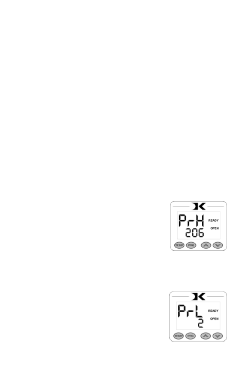
Height Gauge - High Point
Turn the pressure knob to the left to raise
the top head. Do this until the highest level is
reached, without unscrewing the internal bolt
from the main post. Press an arrow key to lock
in that pressure value to PRH. The high point
of the pressure/height gauge is now defined.
Press PRG to move to the next menu item.
Height Gauge - Low Point
Turn the pressure knob to the right to
lower the top head. Do this until the lowest
level is reached. Press an arrow key to lock in
that pressure value to PRL. The low point of
the pressure/height gauge is now defined. Press
PRG to move to the next menu item.
13
Page 14
Pressure / Height Gauge Sensitivity
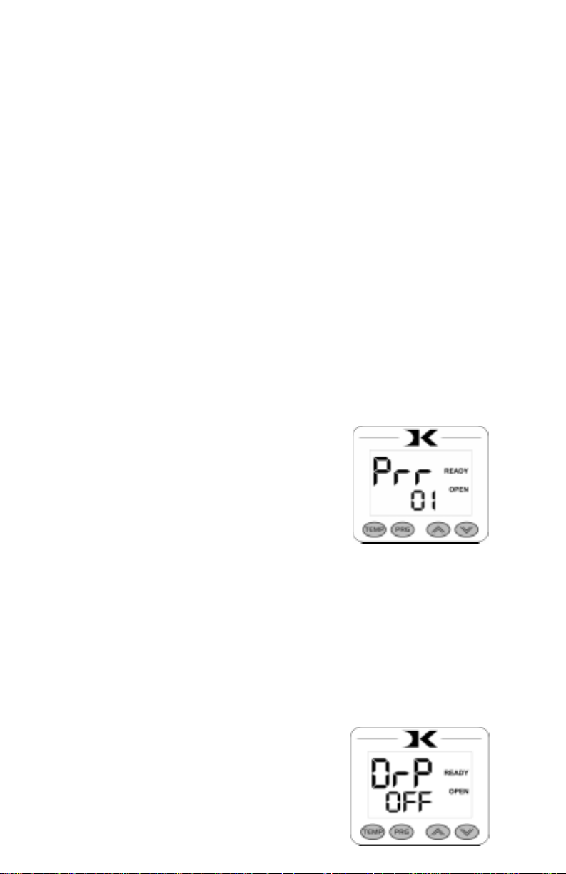
The PRR menu item allows the user to define how sensitive the
height gauge is for displaying purposes. This setting defines how
quickly the pressure display will appear during normal operation.
The lower the sensitivity setting, the less the amount of change is
required when turning the pressure knob to cause the PRS display to
appear during the default operating mode. The higher the number, the
greater the amount of change in height is required to display the PRS
value.
Usually a setting of 02 is fine for normal operation. However,
sometimes merely closing the press can cause the pressure/height gauge
to register a reading and change the display to the PRS reading
undesirably . By increasing this value, the PRS display will not activate
from smaller changes to the pressure. Conversely, sometimes the
operator may adjust the pressure knob, but the PRS value does not
display unless the knob is turned very quickly . By lowering the value,
the display will activate based on smaller and slower changes to the
pressure setting.
Use the arrow keys to change the PRR
sensitivity setting. Press PRG to move to the
next menu item.
Drop Sense
A temperature alarm is available for warning the user of out-ofrange temperature conditions. The user can set this menu item to
sound an alarm if the heat platen drops below the Set Point temperature
by the amount indicated. This can be helpful when pressing substrates
that absorb an unusually large amount of heat, causing the platen to
fall in temperature quickly. If the results of the transfer begin to
deteriorate, the Drop Sense feature can help the user avoid this.
Use the arrow keys to set the degrees or
to turn this feature off. If the Current
temperature drops below the Set Point by this
amount or more, an alarm will sound. The
default value is OFF.
14
Page 15
Beep
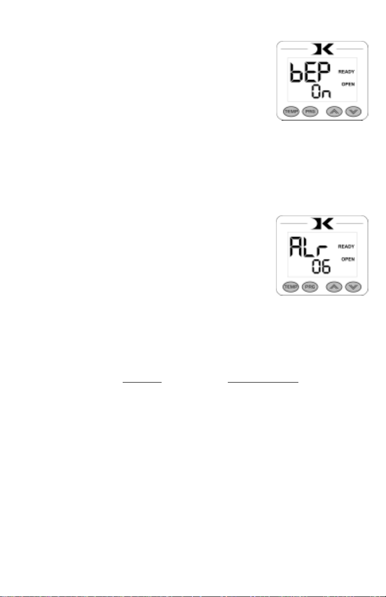
Normally , all buttons on the keypad beep
when pressed. This can be turned off, so all
button keypresses are silent. Use the arrow
keys to turn this feature On or Off.
Alarms
There are 10 different alarms available to choose from. These
alarms are sounded at the end of the timing cycle, as well as if the
Drop Sense feature is enabled.
Use the arrow keys to change the values
or to turn the alarm off. Please note the different
alarms below.
• denotes a short beep.
_ denotes a longer beep.
~ denotes infinite loop.
Alarm # Alarm Pattern
Of f No alarm
01 • • • _
02 • • • _ ~
03 • • _
04 • • _ ~
05 • • •
06 • • • ~
07 _ ~
08 _
09 •
10 • (shorter)
15
Page 16

Maintenance
The majority of the press has been designed to be as maintenance
free as possible. There are only a few aspects of the machine that
should be monitored to insure proper operation.
• The clamp/linkage assembly is the greatest area of wear and friction
on the press. The posts that connect to the heat platen should be
lubricated with SuperLube - a clear high-temperature lubricant. Do
not use grease, white lithium, or WD-40 to lubricate the clamp/linkage
assembly.
• Check the power cord and heat platen connector cords regularly to
make sure there are no visible signs of damage. Make sure the modular
cord does not come in contact with the underside of the heater. The
modular cords should travel from under the head back away from the
machine.
• The silicone pad on the lower table can degrade after much use and
over an extended period of time. This pad is replaceable. If the pad
becomes dried out, cracked, or there are chunks removed from the
silicone pad, this can result in inconsistent and poor quality transfers.
16
Page 17

Troubleshooting
The following information attempts to address the most probable
mechanical and user issues with the press. Most issues with heat
transfer presses are application related. That is, they have to do with
the results of a particular transfer application.
For technical support on problems having to do with the final
results of a particular transfer paper or media, please contact the
supplier of that transfer media. Generally, the machinery manufacturer
is unable to support the myriad of different transfer papers, inks and
imprintable items on the market from other resellers.
Q. The timer does not start when I close the heat platen, or the timer does
not reset when I open the press up.
A. There are several probable causes for this. The timer is activated by a
micro-switch under the head of the press. It is located on a sheet metal
bracket with slots. When the head of the machine is opened, the timer’s
lever should be depressed and the small contact button under the lever
should click in. When the head for the machine is lowered, the lever
of the timer switch should move down and the contact button click
out. The timer switch may need to be loosened and moved along the
bracket to a position that allows for the heat platen cover to trigger the
switch. When tightening the switch against the bracket, do not
overtighten, the switch housing can crack very easily.
Q. The control displays Err when it first comes on, and I can not set the
temperature or use the press.
A. The Err message will display if the heating signal from the platen has
been cut off, interrupted, or the heating sensor has failed. Check that
the modular heat platen connector is properly plugged in and secured.
Then check the green heat connector that plugs into the digital control.
This is inside the top head. Unplug the power cord. Remove the two
screws in between the clamp/linkage that hold down the top panel, and
carefully lift the panel up and look inside at the digital controller. At the
top of the controller, there is a green connector that plugs in. This is the
temperature sensor wire. Check to make sure is it properly seated. Be
sure not to unplug any other connectors. The temperature wire connects
to the center of the rear half of the heat platen. Check this connection
as well to see if the connection is correct.
17
Page 18

Troubleshooting (cont.)
Q. I press the keys on the keypad, and there is no sound or response from
the controller.
A. Check the connection of the keypad to the controller. This is inside
the top panel. Unplug the power cord. Remove the two screws in
between the clamp/linkage that hold down the top panel, and carefully
lift the panel up and look inside at the digital controller. The keypad
connector passes in through the top panel. It should wind around the
first circuit board and be seated fully into the connector. Check the
black keypad connector that plugs into the circuit board to see if it has
pulled apart. Also check the area where the keypad connects to the
front membrane to see if the leads have been damaged. The membrane
keypad may need to be replaced.
Q. The clamp becomes extremely difficult to open and close, and
sometimes binds up.
A. The linkage pins and the posts that connect to the heat platen must be
lubricated with SuperLube - a clear, high temperature lubricant. Lower
the heater but do not clamp the press. Remove the e-clips & linkage
pins and carefully drop the heat platen down from the clamp/linkage
assembly. Make sure there is no tension on the electrical connections
from the heat platen to the top head. Thoroughly clean the posts that
come out of the heat platen, as well as the pins, the holes the pins pass
through, and the holes the heat platen posts pass through. Relubricate
the posts, pins, and all holes & areas in the clamp assembly that receive
motion, and reconnect the assembly.
Q. The press has shut off, and will not come back on after checking the
power cord, on/off switch, etc.
A. Check the fuse. In the back panel of the control box, the power cord
socket has a built-in fuse-holder. Unplug the power cord, and gently
pry out the fuse-holder. If the fuse is burnt out or there is no continuity,
replace it. If the fuse is fine, check the black and white wire connections
from the power socket to the on/off switch, and from the on/off switch
to the controller.
Q. I pressed a transfer upside down. The inks and transfer material have
burned onto the heat platen.
A. Cool the press down. Using a nonabrasive detergent or cleaner, thoroughly
scrub the heat platen surface. Do not use an abrasive scrubber, or a pad
that will scratch the Teflon coating of the platen. If you are still unable to
remove the transfer material, obtain teflon heater block cleaner from the
contact information located at the end of this manual.
18
Page 19

Limited Warranty
Geo Knight & Co warrants that the press is free from defects in both material and
workmanship One Year from the date of invoice to the buyer. If any parts or workmanship are found to
be defective in manufacture, Geo Knight & Co will repair or replace the defective parts or workmanship.
In addition, Geo Knight & Co warrants that the Digital Knight heat control is free from defects in both
material & workmanship and is covered under no-charge support for (3) years. Geo Knight & Co also
warrants that the heating element is warranted for the lifetime of the press, provided it is owned by the
original purchaser. This lifetime warranty on the heating element does not cover temperature sensor
failure, damage or disconnection. This warranty covers all parts to repair the defects, except when
damage results from accident, alteration, misuse or abuse, or when the machine has been improperly
installed, or modified in any way. If the press becomes defective during the limited warranty period of
one year for the entire press, three years for the control, or the lifetime of the heating element, Geo
Knight & Co reserves the right to recall the defective press to the factory for repairs if on site component
replacement is deemed not possible by Geo Knight & Co. A return authorization must be granted by
Geo Knight & Co prior to its return.
If a press covered by the one year limited warranty must be returned to the factory for
repairs, Geo Knight & Co shall make every effort to repair buyer’s press. However, Geo Knight & Co
reserves the exclusive right to determine whether to repair or replace a defective press. If Geo Knight
& Co authorizes a replacement press, the warranty of the replacement press shall expire on the
anniversary date of the original machine’s invoice to the buyer.
There are no warranties which extend beyond the description on the face hereof. Seller
disclaims any implied warranty of merchantability and/or any implied warranty of fitness for a particular
purpose, and buyer agrees that the goods are sold “as is”. Geo Knight & Co does not warrant that the
functions of the press will meet the buyers requirements or expectations. The entire risk as to use,
quality and performance of the press lies with the buyer. In no event will Geo Knight & Co be liable
for any damages, including loss of profits, destruction of goods or any other special, incidental,
consequential or indirect damages arising from the use of the press or accompanying materials. This
limitation will apply even if Geo Knight & Co or its authorized agent has been advised of the possibility
of such damage.
19
Page 20

20
 Loading...