

Page 1

GP-2300/2301 Series
User Manual
Digital Electronics Corporation
Page 2
Preface
Thank you for purchasing the Pro-face GP-2300/2301 Series programmable
operator interface (hereafter referred to as the "GP unit").
This GP unit, with its expanded functionality and improved overall performance,
is an upgrade of Pro-face's previous GP series panels. GP-2300/2301 Series units
allow you to use the Ethernet (GP-2300 Series only) and CF Card features without attaching separately sold expansion units.
Please read this manual carefully as it explains, step by step, how to use the GP
correctly and safely .
Also, in this manual's examples, the Mitsubishi MELSEC-AnA Series PLC is
referred, whenever possible, as a point-to-point connection.
<Note>
1) It is forbidden to copy the contents of this manual, in whole or in part,
except for the user’s personal use, without the express permission of Digital
Electronics Corporation of Japan.
2) The information provided in this manual is subject to change without notice.
3) This manual has been written with care and attention to detail; however,
should you find any errors or omissions, please contact Digital Electronics
Corporation and inform them of your findings.
4) Please be aware that Digital Electronics Corporation shall not be held liable
by the user for any damages, losses, or third party claims arising from any
uses of this product.
All Company/Manufacturer names used in this manual are the registered trademarks of those companies.
© 2003 Digital Electronics Corporation
GP-2300/2301 Series User Manual 1
Page 3
Preface
Preface.........................................................................................................................1
Table of Contents.......................................................................................................2
Essential Safety Precautions....................................................................................6
General Safety Precautions ...................................................................................10
GP-2300/2301 Series Model Names ......................................................................12
Package Contents ....................................................................................................12
UL/c-UL (CSA) Application Notes .......................................................................13
CE Marking Notes ................................................................................................... 14
Revision Information..............................................................................................14
Documentation Conventions..................................................................................14
Table of Contents
CHAPTER 1 INTRODUCTION
1.1 Prior to Operating the GP......................................................................1-1
1.2 System Design ............................................................................................1-2
1.2.1 GP-2300 Series System Design ..................................................... 1-2
1.2.2 GP-2301 Series System Design ..................................................... 1-4
1.3 Accessories..................................................................................................1-8
CHAPTER 2 SPECIFICATIONS
2.1 General Specifications.............................................................................2-1
2.1.1 Electrical ........................................................................................ 2-1
2.1.2 Environmental................................................................................ 2-2
2.1.3 Structural........................................................................................ 2-2
2.2 Functional Specifications........................................................................2-3
2.2.1 Display ........................................................................................... 2-3
2.2.2 Memory.......................................................................................... 2-4
2.2.3 Touch Panel • Clock....................................................................... 2-4
2.2.4 Interfaces ....................................................................................... 2-5
2.3 Interface Specifications...........................................................................2-6
2.3.1 Serial Interfaces.............................................................................. 2-6
2.3.2 Expansion Serial Interface ............................................................. 2-7
2.3.3 Printer Interface.............................................................................. 2-8
2.4 Part Names and Functions ......................................................................2-9
GP-2300/2301 Series User Manual2
Page 4
2.5 Dimensions............................................................................................... 2-12
2.5.1 GP-2300/2301 Series External Dimensions................................. 2-12
2.5.2 Panel Cut Dimensions.................................................................. 2-13
2.5.3 Installation Fasteners.................................................................... 2-14
CHAPTER 3 INSTALLATION AND WIRING
3.1 Installation ..................................................................................................3-1
3.1.1 Installation Procedures................................................................... 3-1
3.2 Wiring Precautions ...................................................................................3-6
3.2.1 Connecting the Power Cord ........................................................... 3-6
3.2.2 Connecting the Power Supply....................................................... 3-8
3.2.3 Grounding ...................................................................................... 3-9
3.2.4 I/O Signal Line Placement ............................................................. 3-9
Preface
3.3 Tool Connector ....................................................................................... 3-10
3.4 Ethernet Cable Connector................................................................... 3-10
3.5 CF Card Insertion and Removal.........................................................3-11
3.5.1 CF Card Handling ........................................................................ 3-13
CHAPTER 4 DATA TRANSFER
4.1 Serial Data Transfer .................................................................................4-1
4.2 Ethernet Data Transfer ...........................................................................4-4
4.2.1 Checking the IP Address................................................................ 4-6
4.3 CF Memory Loader Tool.........................................................................4-7
4.3.1 Data Upload and Download........................................................... 4-8
CHAPTER 5 OFFLINE MODE
5.1 Entering OFFLINE Mode.......................................................................5-1
5.1.1 After Plugging in the Power Cord.................................................. 5-1
5.1.2 From the Menu Bar ........................................................................ 5-2
5.2 OFFLINE Mode Main Menu..................................................................5-3
5.3 Initialization...............................................................................................5-4
5.4 Self-Diagnosis.............................................................................................5-6
GP-2300/2301 Series User Manual 3
Page 5

Preface
CHAPTER 6 INITIALIZING THE GP
6.1 Initialization Screen.................................................................................6-1
6.2 Initialization Items ...................................................................................6-2
6.3 System Environment Setup ....................................................................6-3
6.3.1 System Setup.................................................................................. 6-3
6.3.2 System Area Setup ......................................................................... 6-4
6.3.3 Global Window Setup.................................................................... 6-6
6.3.4 Character String Data Setup........................................................... 6-7
6.4 Set Up I/O ................................................................................................ 6-10
6.4.1 Set Up SIO ................................................................................... 6-10
6.4.2 Communication Setup.................................................................. 6-12
6.4.3 Set Up Touch Panel...................................................................... 6-13
6.4.4 Display Setup ............................................................................... 6-16
6.4.5 Set Up Printer............................................................................... 6-17
6.4.6 Expansion Serial Setup ................................................................ 6-19
6.4.7 Expansion Serial Environment Setup .......................................... 6-20
6.4.8 Set Up Capture Operation ............................................................ 6-21
6.4.9 FUNCTION SETUP .................................................................... 6-22
6.4.10 COMMUNICATION PORT SETUP........................................... 6-22
6.5 PLC Setup................................................................................................ 6-23
6.5.1 Set Up Operation Surroundings (1:1/n:1) .................................... 6-23
6.5.2 Station Setup (n:1) ....................................................................... 6-24
6.5.3 Customize Setup (n:1) ................................................................. 6-26
6.5.4 Ethernet Setup.............................................................................. 6-28
6.5.5 SYSLOG Setup ............................................................................ 6-29
6.5.6 Others Setup................................................................................. 6-30
6.5.7 Self-Diagnosis.............................................................................. 6-30
6.6 Initialize Internal Memory.................................................................. 6-31
6.6.1 Initialize GP Memory................................................................... 6-31
6.6.2 Initialize CF Card......................................................................... 6-31
6.6.3 CSV DATA INDEX ..................................................................... 6-32
6.7 Set Up Time............................................................................................. 6-33
6.8 Set Up Screen.......................................................................................... 6-34
6.9 Font Setting ............................................................................................. 6-35
GP-2300/2301 Series User Manual4
Page 6
CHAPTER 7 RUN MODE AND ERRORS
7.1 RUN Mode ..................................................................................................7-1
7.1.1 After Connecting the Power Cord.................................................. 7-1
7.1.2 V ia OFFLINE Mode ...................................................................... 7-2
7.2 Self-Diagnosis.............................................................................................7-3
7.2.1 Self-Diagnosis Item List ................................................................ 7-3
7.2.2 Self-Diagnosis - Details ............................................................... 7-4
7.3 Troubleshooting .........................................................................................7-7
7.3.1 Possible Types of Trouble .............................................................. 7-7
7.3.2 No Display ..................................................................................... 7-8
7.3.3 No GP/Host Communication ....................................................... 7-11
7.3.4 Touch Panel Does Not Respond .................................................. 7-13
Preface
7.3.5 Buzzer Sounds when GP power is turned ON ............................. 7-14
7.3.6 Clock Settings Cannot be Entered ............................................... 7-15
7.3.7 Error Screens................................................................................ 7-15
7.4 Error Messages....................................................................................... 7-16
7.4.1 Error Message List ....................................................................... 7-16
7.5 Error Message Details .......................................................................... 7-18
7.5.1 System Errors............................................................................... 7-18
7.5.2 Illeagal Address in Screen Data ................................................... 7-20
7.5.3 PLC Com. Error ........................................................................... 7-21
7.5.4 Clock Setup Error ........................................................................ 7-22
7.5.5 Screen Tag Limit Exceeded (max. of 384)................................... 7-22
7.5.6 OBJ. PLC Has Not Been Setup.................................................... 7-22
7.5.7 D-Script and Global D-Script Errors ........................................... 7-23
7.5.8 Extended SIO Script Error ........................................................... 7-24
CHAPTER 8 MAINTENANCE
8.1 Regular Cleaning ......................................................................................8-1
8.1.1 Cleaning the Display...................................................................... 8-1
8.1.2 Installation Gasket Check/Replacement ........................................ 8-1
8.2 Periodic Check Points..............................................................................8-3
8.3 Replacing the Backlight ..........................................................................8-4
INDEX
GP-2300/2301 Series User Manual 5
Page 7
Preface
Essential Safety Precautions
This manual includes procedures that must be followed to operate the GP correctly and safely. Be sure to read this manual and any related materials thoroughly
to understand the correct operation and functions of this unit.
Safety Icons
Throughout this manual the following icons are provided next to GP operation
procedures requiring special attention, and provide essential safety information.
These icons indicate the following levels of danger:
Indicates situations where severe bodily
W arning
injury, death or major equipment damage
can occur.
Caution
Indicates situations where slight bodily
injury or machine damage can occur.
WARNINGS
System Design
• Do not create GP touch panel switches that could possibly
endanger the safety of equipment and personnel. Damage
to the GP, its I/O unit(s), cable(s), and other related equipment can cause an output signal to remain continuously
ON or OFF and possibly cause a major accident. Therefore, design all monitoring circuits using limit switches,
etc. to detect incorrect device movement. To prevent accidents related to incorrect signal output or operation, design all switches used to control vital machine operations
so they are operated via a separate control system.
• Please design your system so that equipment will not
malfunction due to a communication fault between the GP
and its host controller . This is to prevent any possibility of
bodily injury or material damage.
• Do not use the GP unit as a warning device for critical
alarms that can cause serious operator injury, machine
damage or production stoppage. Critical alarm indicators
and their control/activator units must be designed using
stand-alone hardware and/or mechanical interlocks.
• The GP is not appropriate for use with aircraft control
devices, aerospace equipment, central trunk data transmission (communication) devices, nuclear power control
devices, or medical life support equipment, due to these
devices’ inherent requirements of extremely high levels of
safety and reliability.
GP-2300/2301 Series User Manual6
Page 8
Preface
WARNINGS
• Do not create switches used to control machine safety
operations, such as an emergency stop switch, or a GP
touch screen icon. Be sure to install these switches as
separate hardware switches, otherwise severe bodily
injury or equipment damage can occur.
• When using the GP with : transportation vehicles (trains,
cars and ships), disaster and crime prevention devices,
various types of safety equipment, non-life support related medical devices, etc., redundant and/or failsafe
system designs should be used to ensure the proper degree of reliability and safety.
Touch Panel
• After the GP’s backlight burns out, unlike the GP’s
“Standby Mode”, the touch panel is still active. If the operator fails to notice that the backlight is burned out and
touches the panel, a potentially dangerous machine operation error can occur.
If your GP's backlight suddenly turns OFF, use the follow-
ing steps to determine if the backlight is actually burned out.
1) If your GP is
screen has gone blank, your backlight is burned out.
2) Or, if your GP
the screen does not cause the display to reappear,
your backlight is burned out.
Also, use the GP’s built-in “USE TOUCH PANEL AFTER
BACKLIGHT BURNOUT” feature to prevent an accidental
machine operation error. This feature can automatically
detect a burnout and disable the touch screen.
Wiring
• To prevent electrical shock or equipment damage, unplug
the GP unit’s power cord from the power supply prior to
installing or wiring the GP.
• Be sure to replace the GP's plastic terminal block cover
after wiring is completed, since operating the GP without
the cover may lead to an electric shock
• Do not use power beyond the GP's specified voltage
not set to "Standby Mode" and the
is set to Standby Mode, but touching
range. Doing so may cause a fire or an electric shock.
GP-2300/2301 Series User Manual 7
Page 9
Preface
WARNINGS
Battery Replacement
• The GP uses a lithium battery for backing up its internal
clock data. If the battery is incorrectly replaced, the battery may explode. To prevent this, please do not replace
the battery yourself. When the battery needs to be re-
placed, please contact your local GP distributor.
Installation/Maintenance
• High voltage runs through the GP. Except for replacing
the backlight, never take apart the GP, otherwise an electrical shock can occur.
• Do not modify the GP unit. Doing so may cause a fire or
an electric shock.
• Do not use the GP in an environment where flammable
gasses are present, since operating the GP may cause an
explosion.
CAUTIONS
Installation/Maintenance
• Be sure to securely connect all cable connectors to the GP.
A loose connection may cause incorrect input or output.
GP-2300/2301 Series User Manual8
Page 10
Preface
CAUTIONS
Wiring
• Ground the GP's FG line separately from other units’ FG
lines. Putting these FG lines too close may cause an electric shock or unit malfunction. Be sure to use a grounding
resistance of 100
ΩΩ
Ω or less and a 2mm
ΩΩ
your country’s applicable standard.
• Be sure the GP's rated voltage is within the designated
range, and that the power terminal lines are correctly
attached. If the voltage supplied differs from the rated
voltage, or incorrect wiring or grounding is performed, it
may cause a fire or unit malfunction.
• Use only the designated torque to tighten the GP's termi-
nal block screws. If these screws are not tightened firmly,
it may cause a short-circuit, fire, or GP malfunction.
2
or thicker wire, or
• Be careful that metal filings and wiring debris do not fall
inside the GP, since they can cause a fire, GP malfunction, or incorrect unit operation.
Display Device/CF Card
• The liquid crystal panel contains a powerful irritant and if
for any reason the panel is damaged and this liquid contacts any part of your body, be sure to wash that area with
running water for 15 minutes. If any of this liquid enters
your eye, flush your eye for 15 minutes with running water
and contact a physician.
• Prior to inserting or removing a CF Card, be sure the CF
Card ACCESS lamp is not lit. If you do not, CF Card internal data may be damaged or lost.
• While a CF Card is being accessed, NEVER turn OFF or
reset the GP, or insert or remove the CF Card. Prior to
performing these operations, create and use a special GP
application screen that will prevent access to the CF
Card.
Refer to GP-PRO/PB III for Windows Tag Reference Manual
(included in the screen editor software package)
Unit Disposal
• When this unit is disposed of, it should be done so ac-
cording to your country's regulations for similar types of
industrial waste.
GP-2300/2301 Series User Manual 9
Page 11

Preface
General Safety Precautions
About the Operation Environment
• Do not strike the touch panel with a hard or pointed object, or press
on the touch panel with too much force, since it may damage the
touch panel or the display.
• Do not install the GP where the ambient temperature can exceed the
allowed range. Doing so may cause the GP to malfunction or shorten
its operation life.
• Do not restrict or limit the GP’s naturally occurring rear-face ventila-
tion, or store or use the GP in an environment that is too hot.
• Do not use this unit in areas where large, sudden temperature
changes can occur. These changes can cause condensation to form
inside the unit., possibly causing the unit to malfunction.
• Do not allow water , liquids, metal or charged particles to enter inside
the GP’s case, since they can cause either a GP malfunction or an
electrical shock.
• Do not use or store the GP in direct sunlight, or in excessively dusty
or dirty environments.
• Do not store or use the unit where strong jolting or excessive vibra-
tion can occur.
• Do not store or use the GP where chemicals (such as organic sol-
vents, etc.) and acids can evaporate, or where chemicals and acids
are present in the air.
Corrosive chemicals: Acids, alkalines, liquids containing salt
Flammable chemicals: Organic Solvents
• Do not use paint thinner or organic solvents to clean the GP, since
they can cause either discoloration or a GP malfunction.
• Do not store or operate the LCD display in areas receiving direct
sunlight, since the sun's UV rays may cause the LCD display’s quality to deteriorate.
• Storing this unit in areas at a temperature lower than is recommended
in this manual’s specifications may cause the LCD display’s liquid
to congeal, which may damage the panel. Conversely, if the storage
area’s temperature becomes higher than the allowed level, the LCD’s
liquid will become isotropic, causing irreversible damage to the LCD.
Therefore, be sure to store the panel only in areas where temperatures are within those specified in this manual.
• Do not connect or disconnect the communication cable between the
GP and the host during power-ups.
GP-2300/2301 Series User Manual10
Page 12
Preface
About the Screen Data
• Due to the possibility of unexpected accidents, be sure to back up
the GP’s screen data regularly.
About the GP's Display Panel
• The GP's currently displayed data, its voltage*1 and brightness setting each affect the intensity of Contouring. (i.e, when some parts of
the screen are brighter than others, creating a wavelike pattern)
• There are minute grid-points (dark and light) on the Display Panel's
surface. This is part of the GP's design and not a defect.
• Extended shadows, or "Crosstalk" may appear on the sides of screen
images. This is normal for an LCD display.
• Sometimes the display area may look as if the display colors have
changed. This is a common attribute of LCD's and is not a defect.
• Displaying a single image for long periods can cause an afterimage
to remain when the display is changed to another screen.
To prevent this effect:
Use the GP's "Stand-by Mode", which automatically turns the
screen OFF when there is no input for a specified period of
time.
6.3.1 System Setup
• Write “FFFFh” to the System Data Area’s “Screen Display Off”
address *2 to turn the screen display OFF when the following actions are not performed for the user's designated period of time.
• Change Screen
• Touch Screen
• Alarm Display
Do not display any single screen for a long period of time. Try
to periodically change the screen display.
*1 If the GP's voltage is at the very low end of its allowable range, it may effect the
intensity of contouring.
*2 The following addresses assume all System Data Area settings are entered. If they are
not all entered, the correct word address may be different from those given here.
With the Direct Access Method — use System Data Area word address +9
With the Memory Link Method — use System Data Area word address +12
GP-PRO/PB III for Windows Device/PLC Connection Manual
GP-2300/2301 Series User Manual 11
Page 13
Preface
GP-2300/2301 Series Model Names
The GP-2300/2301 Series refers to the following GP model numbers:
GP2000
Series
Se ries Model Na m e Model Type Comme nts
GP-2300
Series
GP-2301
Series
GP-2300L GP2300-LG41-24V GP2300L
GP-2300S GP2300-SC41-24V GP2300S
GP-2300T GP2300-TC4 1-24V GP2300
GP-2301L GP2301-LG41-24V GP2301L
GP-2301S GP2301-SC41-24V GP2301S
GP-2301T GP2301-TC4 1-24V GP2301
UL/c-UL (CSA )
Approved,
CE Marked
GP Type in Scree n
Creation Software
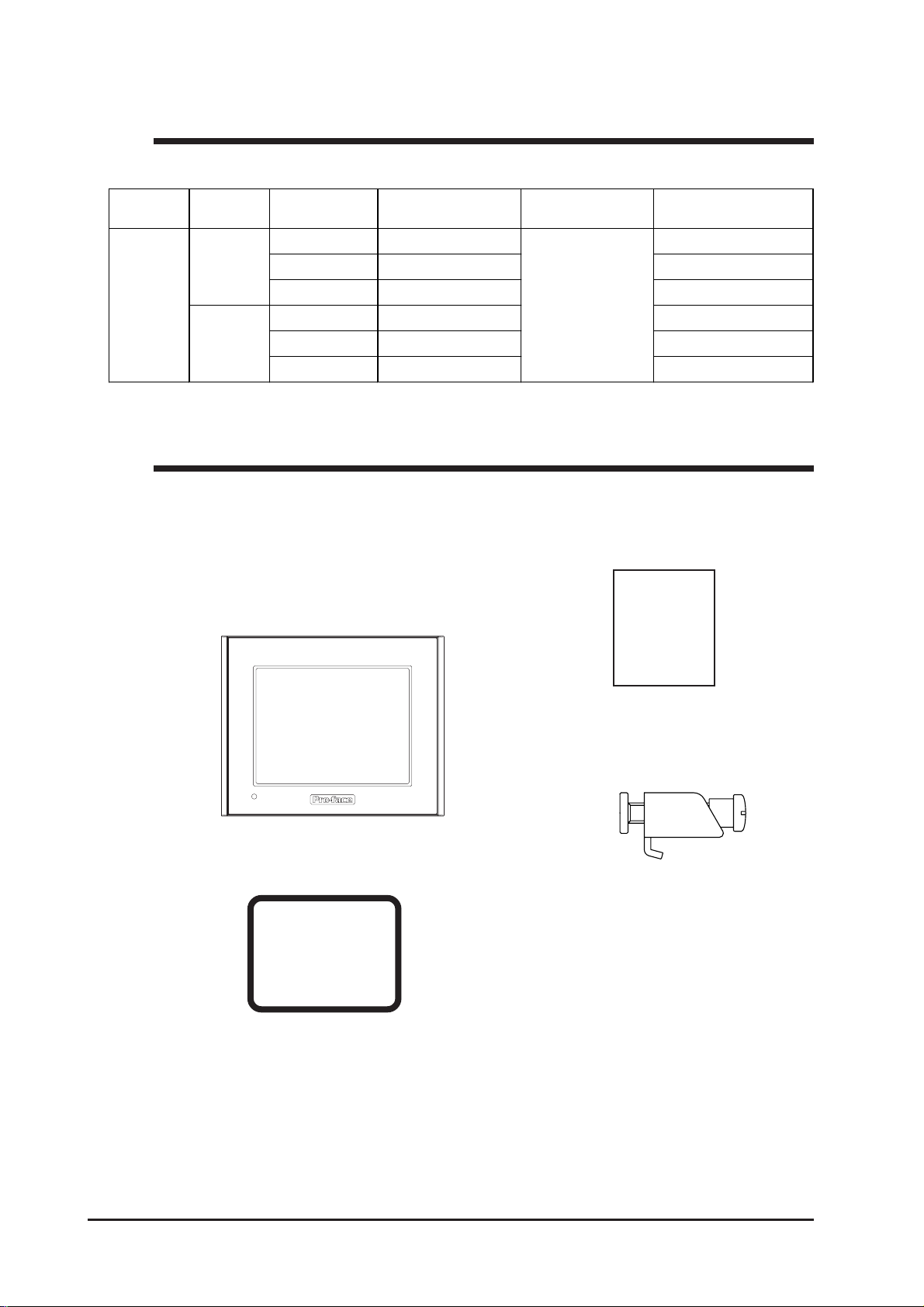
Package Contents
The GP's packing box contains the items listed below. Please check to confirm
that all items shown below have been included.
GP Unit (1)
GP2300-LG41-24V/GP2300-SC41-24V/
GP2300-TC41-24V/GP2301-LG41-24V/
GP2301-SC41-24V/GP2301-TC41-24V
Installation Guide (1)
Installation
Guide
Installation Fasteners
(4/set)
Installation Gasket (1)
<pre-installed>
This unit has been carefully packed, with special attention to quality. However,
should you find anything damaged or missing, please contact your local GP
distributor immediately for prompt service.
GP-2300/2301 Series User Manual12
Page 14

Preface
UL/c-UL (CSA) Application Notes
The GP2300-LG41-24V/GP2300-SC41-24V/GP2300-TC41-24V/GP2301LG41-24V/GP2301-SC41-24V/GP2301-TC41-24V units are UL/c-UL(CSA)
recognized components.
UL file no. E231702(UL60950+UL1604)
When applying for UL approval for a product that includes one of these
GP units, please be sure to pay special attention to the fact that all products
with built-in GP units require UL inspection of the combination of the GP and
the product.
The GP components conform to the following standards:
- UL1604
Safety of Information Technology Equipment for use in Class I and II, Division 2, and Class III Hazardous (classified) locations.
- CAN/CSA-C22.2 No.60950-00 and No.213-M1987
Safety of Information Technology Equipment for use in Class I and II, Division 2, and Class III Hazardous (classified) locations.
GP2300-LG41-24V (UL Registration Model: 2980070-01)
GP2300-SC41-24V (UL Registration Model: 3180050-01)
GP2300-TC41-24V (UL Registration Model: 2980070-02)
GP2301-LG41-24V (UL Registration Model: 2980070-04)
GP2301-SC41-24V (UL Registration Model: 2980070-03)
GP2301-TC41-24V (UL Registration Model: 3180034-02)
*1
and UL60950 Third Edition
Installation Precautions
If the GP is mounted so as to cool itself naturally, please mount it on a vertical
panel. Also, insure that the GP is mounted at least 100 mm away from any
other adjacent structures or machine parts. If these conditions are not met, the
heat generated by the GP’s internal components may cause it to fail to meet UL
standards.
UL1604 - Compliance and Handling Cautions
1. Power and input/output wiring must be in accordance with Class I, Division
2 wiring methods - Article 501-4(b) of the National Electrical Code, NFPA
70 within the United States, and in accordance with Section 18-152 of the
Canadian Electrical Code for units installed within Canada.
2. Suitable for use in Class I, Division 2, Groups A, B, C, and D Hazardous
Locations.
3. WARNING: Explosion hazard - substitution of components may impair
compliance to Class I, Division 2.
4. WARNING: Explosion hazard - when in hazardous locations, turn the power
OFF before replacing or wiring modules.
5. WARNING: Explosion hazard - confirm that the power supply has been
turned OFF before disconnecting equipment, or confirm that the location is not
subject to the risk of explosion.
*1GP2300-LG41-24V units with revision code “L” or later, GP2300-TC41-24V
units with revision code “J” or later, GP2301-LG41-24V units with revision
code “L” or later, and GP2301-SC41-24V units with revision code “K” or
later are all UL1604 compliant. See “Revision Information” in page 14 for
how to identify your unit’s revision code.
GP-2300/2301 Series User Manual 13
Page 15
Preface
CE Marking Notes
The GP2300-LG41-24V, GP2300-SC41-24V, GP2300-TC41-24V, GP2301-LG4124V, GP2301-SC41-24V, and GP2301-TC41-24V are CE marked products that
conform to EMC directives EN55011 Class A and EN61000-6-2.
* For detailed CE marking information, please contact your local GP distributor.
Revision Information
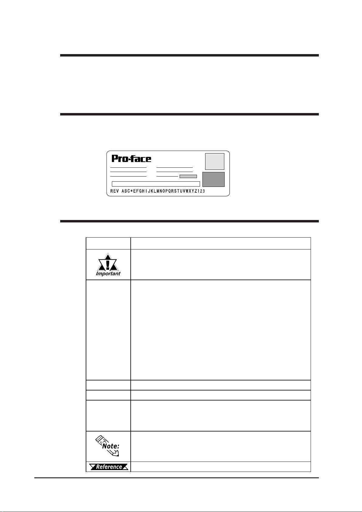
Use the metallic label attached to the rear of the GP to identify your unit’s revision
code. This code is at the bottom of the label, to the right of “REV”. Inthis
example, the asterisk mark (*) is in the “D” position, which means this unit’s
revison code is “D”.
DIGITAL ELECTRONICS CORP.
Documentation Conventions
The list below describes the documentation conventions used in this manual.
Symbol Meaning
Indicates important inf or mation or procedures t hat must be f ollowed f or
correct and risk -free sof tware/ device operation.
Indicates t he GP- P RO/P B III f or Windows screen editor software
(version 6.10 or higher).
GP-PRO/ P B I II f or W ind ows Ver. 6.20 or higher is us ed for t he GP2301T.
GP Screen
Editor
PLC
*1
When using t he GP-2300S, add- on sof t ware must be inst alled. This
sof t w are can be downloaded f r om Pro- face's W eb s ite.
(http://www.pro-face.com/)
For information on how to confirm the version, refer to the “GP-PRO/PB
for Windows Operation Manual”, which is supplied with t he GP s creen
editor softwar e.
Abbrev iat ion f or P rogrammable Logic Controller.
Indicates usef ul or important supplemental information.
1) , 2)
Indicates s teps in a procedure. Be sur e to perf or m thes e s t eps in t he
order given.
Provides usefu l or import ant supplemental inf ormat ion.
Refer s t o us ef ul or import ant s upplemental information.
GP-2300/2301 Series User Manual14
Page 16
1. Prior to Operating the GP
2. System Design
Chapter
3. Accessories
1 Introduction
1.1 Prior to Operating the GP
Be sure to follow these steps when creating projects for the GP unit.
1 Preparation Before using the GP , check that all required hardware is
present and read all specification, wiring, and installation
information.
Chapter 2, "Specifications" and Chapter 3,
"Installation and Wiring"
2 Screen Design Create a sample screen and design a T ag layout, with
the Screen layout sheets and T ag lists provided in the
Editor software.
GP-PRO/PBIII for Windows Operation
Manual
3 Select GP and Using the input areas provided, select the GP and the
PLC types PLC types to be used.
GP-PRO/PBIII for Windows Operation
Manual
GP-PRO/PBIII for Windows Tag
Reference Manual
4 Create Screen/ Run Setup the screen and tags in your screen editing
Screen Setup software according to your Screen Design.
GP-PRO/PBIII for Windows Operation
Manual and Tag Reference Manual
5 Transfer Scr een Data Transfer the data from the Screen editor software on
your PC to the GP unit using the Data Transfer Cable.
GP-PRO/PBIII for Windows Operation
Manual
6 GP/Host Connection Set up the GP so that it can receive data from the Host (PLC).
Chapter 6, "Initializing the GP", and
GP-PRO/ PBIII for Windows Device/PLC Connection
Manual
7 Connect the GP Link the GP with the host (PLC) using the appropriate
GP-2300/2301 Series User Manual
connection cable (different cables may be necessary for
different hosts), and then operate the unit.
GP-PRO/PBIII for Windows Device/PLC
Connection Manual
1-1
Page 17
Chapter 1 - Introduction
1.2 System Design
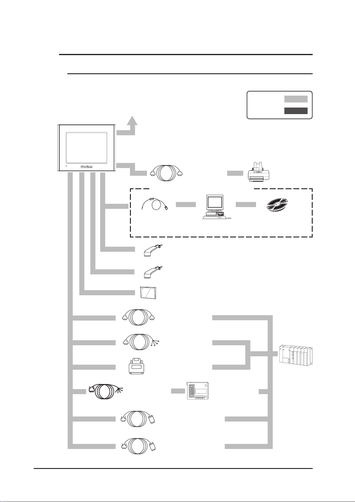
1.2.1 GP-2300 Series System Design
The following diagram represents the standard items connected to the GP-2300 Series unit.
GP RUN Mode Peripherals
RUN Mode
GP Unit
T o an Ethernet Network
(1)
(2)
When using the Internal 2-Port feature
(3)
Data Transfer
Cable
GPW-CB02
(4)
Edit Mode
Printer Cable
PSM-PRCB00
Printer
(Commercial type)
Mitsubishi GPP
Personal
Computer
Bar-Code Reader
(Limited to tested models)
Bar-Code Reader, 2-Dimensional-Code Reader
(Commercial type)
*5
*3
Software
*2
*1
*3
(5)
CF Card
GP077-CF20,
GP077-CF30
(6) (7)
RS-232C Cable
GP410-IS00-O
RS-422 Cable
GP230-IS11-O
GP230-IS12-O
(for Multi-link cable)
RS-422 Connector
Terminal Adapter
GP070-CN10-O
2 Port Adapter II
Cable
GP070-MDCB11
Mitsubishi PLC A-Series
*4
*4
*4
*4
Mitsubishi PLC A,
Q, C, FX Series'
2 Port Adapter II
GP070-MD11
(8)
(9)
(9)
Program Port I/F Cable
GP430-IP10-O
Mitsubishi PLC FX-Series
Program Port I/F Cable
GP430-IP11-O
(9)
Host Controller
PLC etc.
1-2
GP-2300/2301 Series User Manual
Page 18
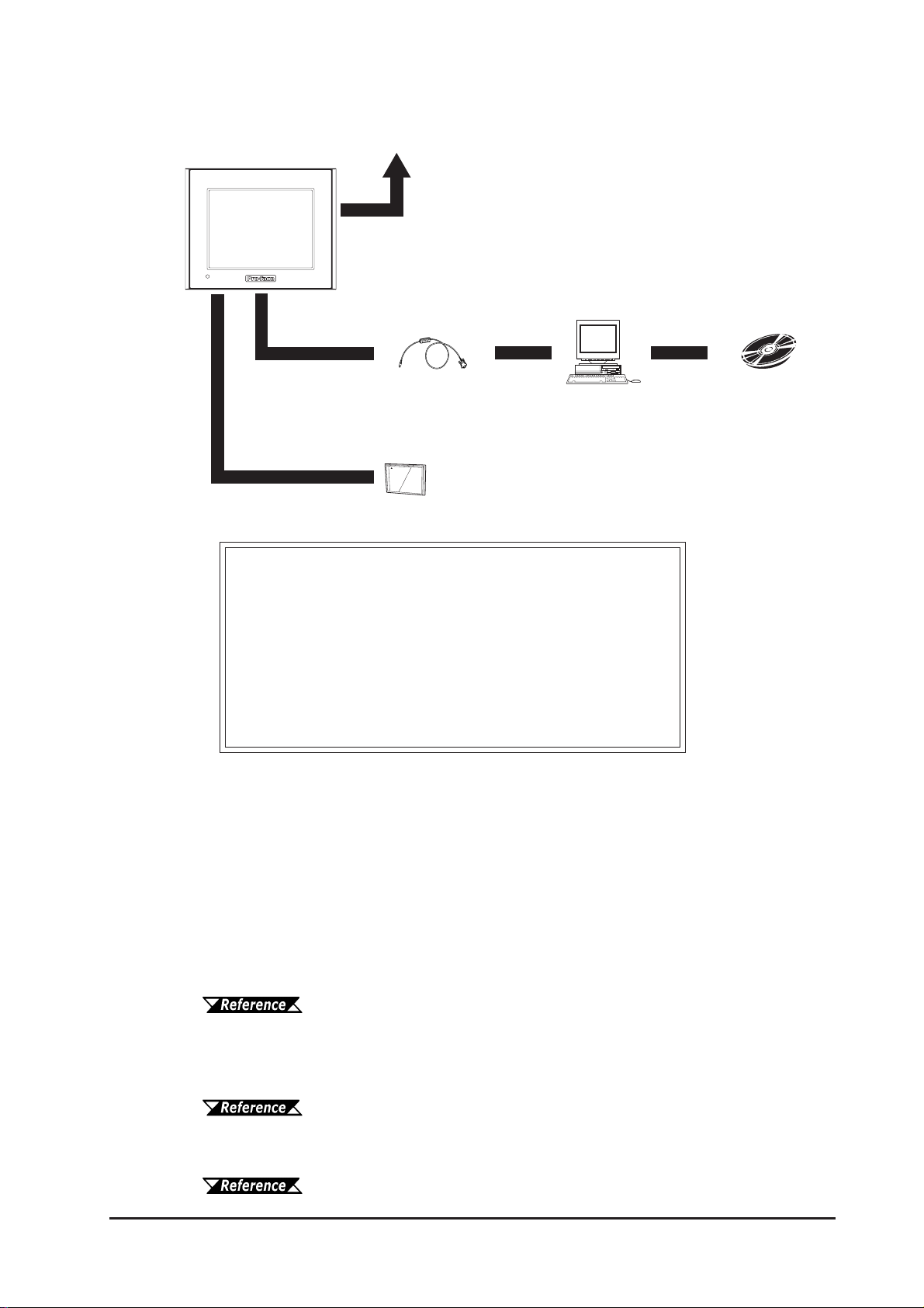
GP Edit Mode Peripherals
Chapter 1 - Introduction
GP Unit
(5)
GP Interfaces
(1) Ethernet
(2) Printer
(3) T ool Connector
(4) Expansion Serial
(5) CF Card
(6) Serial Interface
(3)
T o an Ethernet Network
(1)
Data Transfer
Cable
GPW-CB02
CF Card
GP077-CF20,
GP077-CF30
Personal
Computer
*5
PLC Interfaces
(7) RS-232C Port
(8) RS-422 Port
(9) Programming Port
GP-PRO/PBIII
for Windows
software
*1 Compatible with NECPC-PR201/PL , EPSON ESC/P24-J84(C), HP Laser Jet PCL 4
command printers, EPSON PM/Stylus (6-color ink), EPSON Stylus (4-color ink)
printers or their equivalent that are designed for MS-DOS. Printers designed solely
for Windows may not be used. Certain printers containing both Windows and DOS
drivers may be used. For details, please contact your printer's manufacturer or sales
outlet.
*2 About certain types and models of PLC and software, see:
GP-PRO/PBIII for Windows Device/PLC Connection Manual (included
with the screen editor software)
*3 See Page 1-6 for recommended units.
*4 Certain types and models of PLCs cannot be connected.
GP-PRO/PBIII for Windows Device/PLC Connection Manual (included
with the screen editor software)
*5 Certain types and models of PCs cannot be connected.
GP-PRO/PBIII for Windows Operation Manual (included with the
screen editor software)
GP-2300/2301 Series User Manual 1-3
Page 19

Chapter 1 - Introduction
1.2.2 GP-2301 Series System Design
The following diagram represents the standard items connected to the GP-2301 Series unit.
GP RUN Mode Peripherals
GP Unit
(1)
RUN Mode
Edit Mode
When using the Internal 2-Port feature
(2)
Data Transfer
Cable
GPW-CB02
CF Card
GP077-CF20,
GP077-CF30
Personal
Computer
Bar-Code Reader
(Limited to tested models)
*2
*4
Mitsubishi GPP
Software
(3) (4)
RS-232C Cable
GP410-IS00-O
RS-422 Cable
GP230-IS11-O
GP230-IS12-O
(for Multi-link cable)
RS-422 Connector
Terminal Adapter
GP070-CN10-O
2 Port Adapter II
Cable
GP070-MDCB11
Mitsubishi PLC A-Series
*3
*3
*3
*3
Mitsubishi PLC A,
Q, C, FX Series'
2 Port Adapter II
GP070-MD11
(5)
(6)
(6)
Program Port I/F Cable
GP430-IP10-O
*1
Host Controller
PLC etc.
1-4
Mitsubishi PLC FX-Series
Program Port I/F Cable
GP430-IP11-O
GP-2300/2301 Series User Manual
(6)
Page 20
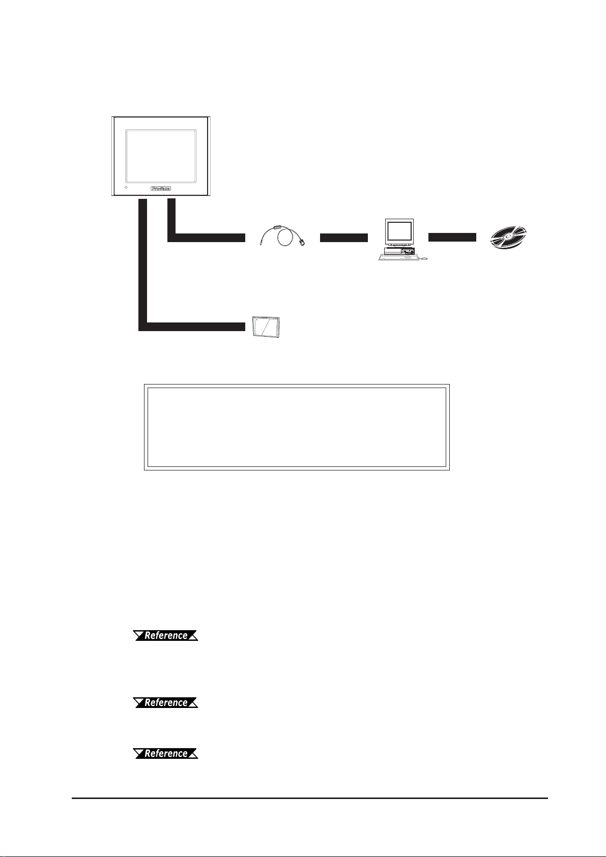
GP Edit Mode Peripherals
GP Unit
(1)
Chapter 1 - Introduction
(2)
GP Interfaces
(1) T ool Connector
(2) CF Card
(3) Serial Interface
Data Transfer
Cable
GPW-CB02
CF Card
GP077-CF20,
GP077-CF30
Personal
Computer
PLC Interfaces
(4) RS-232C Port
(5) RS-422 Port
(6) Programming Port
*4
GP-PRO/PBIII
for Windows
software
*1 About certain types and models of PLC and software, see:
GP-PRO/PBIII for Windows Device/PLC Connection Manual (included
with the screen editor software)
*2 See Page 1-6 for recommended units.
*3 Certain types and models of PLCs cannot be connected.
GP-PRO/PBIII for Windows Device/PLC Connection Manual (included
with the screen editor software)
*4 Certain types and models of PCs cannot be connected.
GP-PRO/PBIII for Windows Operation Manual (included with the
screen editor software)
GP-2300/2301 Series User Manual 1-5
Page 21
Chapter 1 - Introduction
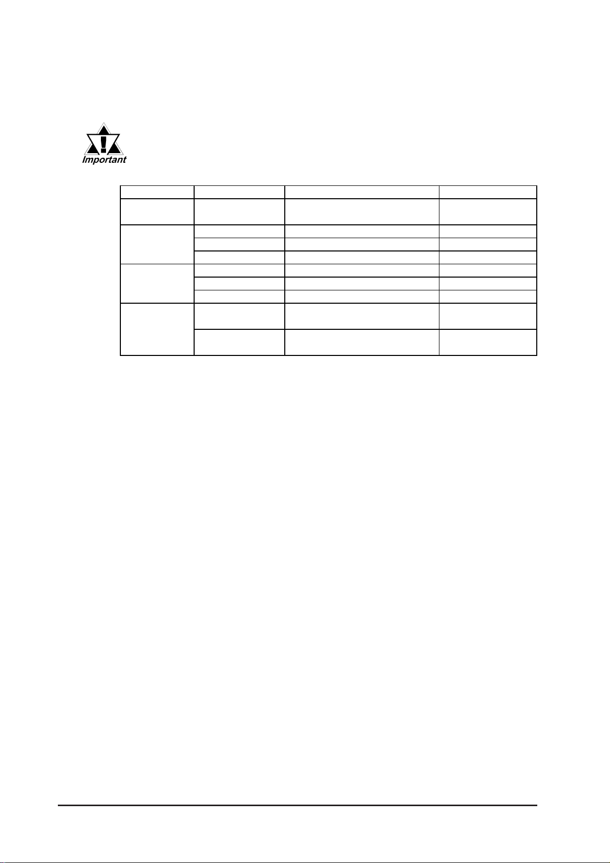
Recommended Units
The following tables list I/O devices that have been confirmed to be compatible with the
GP . If you connect a device other than those listed below, be sure to confirm that the
connection functions correctly using an actual unit.
Recommended units are subject to change without notice.
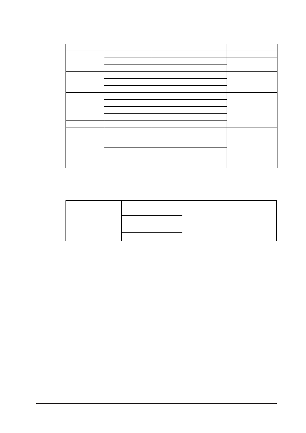
Bar Code Readers (Connected to Tool Connector)
Manufacturer Model Type Description
Aim ex
Corporation
OPT Electronics
Tohken
NEC Infrontia
BR-331 PC2 Pen
OPT-1105-RSK 98 Set Touch Scanner (Read Width: 60mm)
OPT-5105-RSK 98 Set Touch Scanner (Read Width: 80mm)
OPL-6735-RSK 98 Set Touch Scanner (Read Width: 100mm)
TCD-5510M Touch Scanner (Read Width: 65mm)
TCD-5510L Touch Scanner (Read Width: 82mm)
TCD-5510W Touch Scanner (Read Width: 105mm)
BCK5435-STA Touch Scanner (Read Width: 56mm)*1*2
BCK5535-STA Touch Scanner (Read Width: 85mm)*1*2
Includes Y cable for
connection cable
Includes Y cable for
connection cable
*1 Be sure to use the Y cable included with the unit and connect it between GP unit
and a bar code reader. Data cannot be read correctly, if a non-"Y" cable is
used, or if the bar code reader is connected directly to the GP unit.
* 2 The following settings must be entered prior to using the bar code reader with a
GP unit.
1) Set the CAPS.
2) Add the Carriage Return (CR) in the Postamble's settings.
For the details about these settings, please refer to the Installation Guide included with the bar cord unit.
1-6
GP-2300/2301 Series User Manual
Page 22
Chapter 1 - Introduction
Bar Code Readers (Connected to Expansion Serial Interface)
GP-2300 Series Only
Manufacture r Model Type Remarks
Aimex
Corporation
OPT Electronics
Olympus Symbol
Keyence Co. BL-80R Touch Scanner (Read Width: 105mm)
Denso Co.
*1 Confirm that the Expansion serial interface's settings match those of the connected device.
See 6.4.6 Expansion Serial Setup.
2-Dimensional Code Reader (Connected to Expansion Serial Interface)
GP-2300 Series Only
Manufa cturer Model Pow er Supply
Tohken
BR-730RS Pen Battery powered
BR-530RS Pen
BW-665RS Touch Scanner (Read Width: 65mm)
OPT-1125-RS232C Touch Scanner (Read Width: 60mm)
OPT-5125-RS232C Touch Scanner (Read Width: 80mm)
NFT-7175-L-RS232C Fixed Type (Read width: 60mm)
LS4004 Laser Scanner
LS4004i Laser Scanner
LS6004 Laser Scanner
LSH3502AHV Laser Scanner
HC36T R Touch Scanner (Read Width: 61mm)
HC61T R Touch Scanner (Read Width: 61mm)
THIR-3000
ESA-1220A (Sold s e par at ely)
Requires separately
sold BB-60 for power.
Requires separately sold
DC5300T for power.
Includes power supply.
For power:
separately sold
P-200 unit.
For connector cable:
separately sold KRS-423XF1K (Sanwa Supply)
*1
THIR-3000H
Denso
QS20H
contains an external AC adapt er
QS20H-I
*1 Confirm that the Expansion serial interface's settings match those of the connected device.
See 6.4.6 Expansion Serial Setup.
*1
GP-2300/2301 Series User Manual 1-7
Page 23
Chapter 1 - Introduction
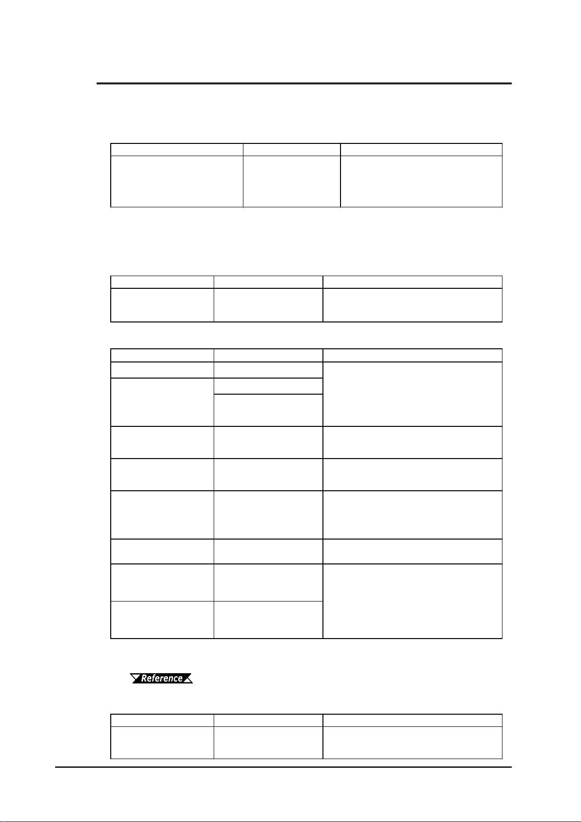
1.3 Accessories
All optional equipment listed here is produced by Digital Electronics Corporation.
Available Software
Product Na m e Mode l No. Description
GP-PROPB III
C-Package02
(GP-PRO/PB III for Windows
*1
Ver. 6.10 or later
*1 GP-PRO/PB III for Windows Ver. 6.20 or higher is used for the GP-2301T
When using the GP-2300S, add-on software must be installed. This software can be
downloaded from Pro-face's Web site. (http://www.pro-face.com/)
Tool Connector
Product Na m e Model No. Description
Screen Data Transfer
Cable
)
GPPRO-CNT01W-P02
GPW-CB02
Software to be used to create the GP's
screen data. I ns t alled in a personal
computer.
Connects t he GP to a personal computer.
Trans f er s s creen dat a and us er prog ram(s) .
Serial Interfaces
Product Na m e Model No. Description
RS-232 C cable
RS-422 cabl es
*1
*1
GP410-IS00-O
GP230-IS11-O
GP230-IS12-O
Int erface cables between t he host (PLC)
and the GP .
(f or Multi- link)
Extension ca bl e
RS-422 Connector
Terminal Adapter
*1
CA1-EXCBL/D25-01
GP070-CN10-O
*1
Ext e nds GP RS -232 C/ 422 s er ial int er f ace
cables (Approx. 1 ft . )
Conv er s ion adapter t o convert s erial dat a t o
RS-422 f ormat
Int erface unit t hat allows use of bot h GP and
2 Port Adapte r I I
GP070-MD11
Mitsubishi A, Q, C and FX s eries per ipher al
equipment.
2 Port Adapte r I I
Cable
Mitsubishi A Serie s
Program m i ng P ort
I/F cable
Mitsubishi FX Seri es
Program m i ng P ort
I/F cable
GP070-MDCB11 Connects t he GP to 2 Port Adapter I I.
GP430-IP10-O
Connects directly to Mitsubishi's PLC
Programming port. S imultaneous use of
programming cons ole, however, is not
GP430-IP11-O
possible.
1-8
*1 For detailed information about the range of connectable PLC manufacturers and
models,
GP-PRO/PBIII for Windows Device/PLC Connection Manual
Printer Interface Cable (GP-2300 Series only)
Product Na m e Model No. Description
Cable designed to connect t he GP and a
Printer Cable
PSM-PRCB00
commercial ty pe printer.
GP-2300/2301 Series User Manual
Page 24
Chapter 1 - Introduction
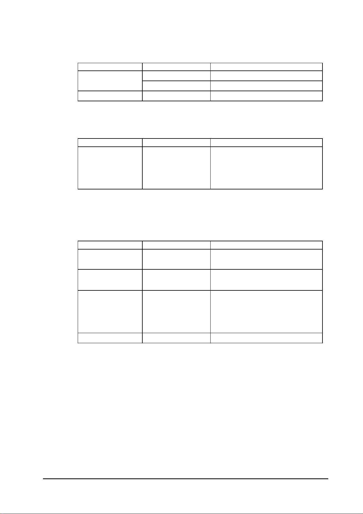
CF Card Items
Product Na m e Model No. Description
CF Card
CF Card Ad ap to r
Screen Protection
Product Na m e Model No. Description
Screen Protection
She et (Hard Type )
GP077-CF20 GP Series CF Card ( 16MB)
GP077-CF30 GP Series CF Card ( 32MB)
GP077-CFAD10 CF Card Adapter f or the PCMCIA Slot.
Disposable, dirt-resistant sheet for the GP's
screen. The GP's touch panel can be
PS300-DF00
operated wit h t his cover sheet attached. (5
sheets/set)
Maintenance Items
They are available separately as optional maintenance items.
Product Na m e Model No. Description
Backlight
Installation Fastener
Installation Gasket
Connector Cove r
PS300-BU00
GP070-AT01
PS300-WP00
PS-BH00 Attaches to GP rear face connectors. (3/set)
Replacement B acklight for the GP-2 300L,
GP-2300S, GP -2301L and GP-2301S.
Fastener s t o at tach the GP to a pane l.
(4 fasteners/set)
Provides a mois t ur e re sis t ant s eal when
installing the GP. Same as the seal
included in the GP' s or iginal equipment
package.
GP-2300/2301 Series User Manual 1-9
Page 25

Memo
1-10
GP-2300/2301 Series User Manual
Page 26
1. General Specifications
2. Functional Specifications
Chapter
3. Interface Specifications
2 Specifications
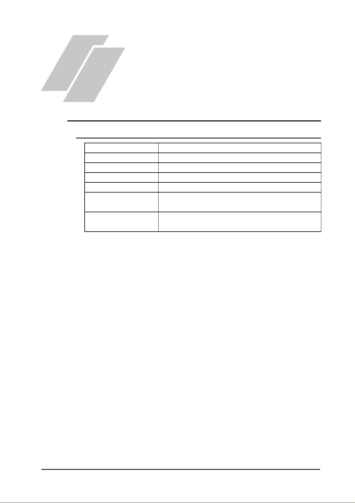
2.1 General Specifications
2.1.1 Electrical
4. Part Names and Functions
5. Dimensions
Ra ted V oltage
Rated Vol ta ge Range
Allowable Voltage Drop
Pow er Consum ption
In-Rush Current
Volta ge Endura nce
Insu la t ion R esist an ce
DC 24V
DC19.2V to 28.8V
10ms or less
22W or les s
30A or less
AC1,000V 20mA f or 1 minut e
(between charging and FG terminals)
20MΩ or higher at DC500V
(between charging and FG terminals)
GP-2300/2301 Series User Manual 2-1
Page 27
Chapter 2 - Specifications
g
2
2
µ
(
)
(
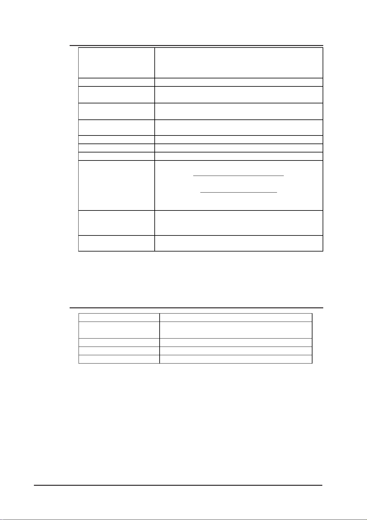
2.1.2 Environmental
Ambient Operatin
Temperature
(Cabinet Interior)
(Panel Face)
Storage Temperature
Opera ting Humi di ty
Storage Humidity
Atmosheric Endurance
(GP Operation Altitude)
Air Puri ty (Du st)
Poll ution Degree
Corro sive Gasses
Vibra tion Re sistance
Noise Immunity
(via noise simulator)
Electrostatic Discharge
Immunity
*1 The LCD displays of GP-2300L, GP-2300S, GP-2301L and GP-2301S may
occasionally blur when they are used for hours at over 40
temperature. This is a temporal phenomenon. After the temperature returns to
normal, the normal display will be restored. The GP’s operation will not be
affected even though the display is blurred.
0oC to +50oC
*1
-20oC to +60oC
10%RH to 90%RH
(Non condensing, wet bulb temperature: 39
10%RH to 90%RH
(Non condensing, wet bulb temperature: 39
800hPa t o 1 , 114hP a (2,000 meters or lower)
0.1mg/m3 or less ( non- conductive levels)
Pollution Degree 2
Free of corrosiv e gasses
IEC61131-2 compli ant
W hen vibration is NOT cont i nuous
10Hz to 57Hz 0.075mm, 57Hz to 150Hz 9.8m/s
W hen vibration is continuous
10Hz to 57Hz 0.035mm, 57Hz to 150Hz 4.9m/s
X, Y, Z directions for 10 times (80min.)
Noise Voltage: 1, 00 0Vp-p
Pulse Duration: 1
s
Rise Time: 1ns
6kV (complies with E N 6100 0-4- 2 Level 3)
0
C ambient operating
o
C or less)
o
C or less)
2.1.3 Structural
Grounding
Ratings
For front panel of installed unit
Externa l Dim ensions
Weight
Cooling Me thod
*1
*1 The front face of the GP unit, installed in a solid panel, has been tested using
conditions equivalent to the standards shown in the specification. Even though
the GP unit’s level of resistance is equivalent to these standards, oils that should
have no effect on the GP can possibly harm the unit. This can occur in areas
where either vaporized oils are present, or where low viscosity cutting oils are
allowed to adhere to the unit for long periods of time. If the GP’s front face
protection sheet becomes peeled off, these conditions can lead to the ingress of
oil into the GP and separate protection measures are suggested. Also, if nonapproved oils are present, it may cause deformation or corrosion of the front
panel’s plastic cover. Therefore, prior to installing the GP be sure to confirm the
type of conditions that will be present in the GP’s operating environment. If the
installation gasket is used for a long period of time, or if the unit and its gasket
are removed from the panel, the original level of the protection cannot be guaranteed. To maintain the original protection level, be sure to replace the installation gasket regularly.
100Ω or less , or your countr y's applicable stan dar d
Equivalent to I P 65f ( J E M 1030),
NEMA #250 Type4X/12
W171 mm [6.73in] x H138mm [5. 43in] x D60mm [2.36in]
2.6lb) or less
1.2kg
Natural air circulation
2-2
GP-2300/2301 Series User Manual
Page 28
Chapter 2 - Specifications
*
2.2 Functional Specifications
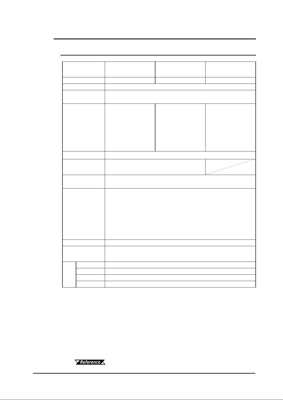
2.2.1 Display
Type
Resolution
Effective Display
Area
Colors
Backlight
Contrast
Adjus tment
Brightness
Adjus tment
Language Fonts
Character Sizes
Font Sizes
8x8 dots
Text
8x16 dot s
16x16 dots
32x32 dots
GP2300-LG41-24V
GP2301-LG41-24V
GP2300-SC41-24V
GP2301-SC41-24V
GP2300-TC41-24V
GP2301-TC41-24V
Monochrome LCD STN type color LCD TFT type color LCD
320 x 240pix els
W115 . 2mm [4. 54in.] x H86.4mm [ 3. 4 0in. ]
Black and Wh it e,
2 lev e ls of gray/
Black and Wh it e,
8 lev e ls of gray
*1
(Color s w it ching is do ne
64 colors/ 3-speed blink
256/No blink
64 colors/ 3-speed blink
(Color s w it ching is do ne
via software)
via software)
o
CCFL (Service lif e: 50, 0 00 hrs . at 25
C and 24hr. oper at ion)
8 lev els of adjustment available via touch panel.
4 lev els of adjustment available via touch panel.
ASCI I : (Code page 850) Alphanumeric (incl. E ur . characters )
Chinese: (GB2312-80 codes) simplified Chinese font s
Japanese: ANK 158, Kanji : 6, 962 ( JIS St andards 1 & 2)
(including 607 non-kanji characters )
Korean: ( K SC5601 - 1992 codes) Hangul fonts
Taiwanese: ( Big 5 codes) t radit ional Chinese fonts
3
8X8, 8X 16, 16X 16 an d 32X 32 dot fonts
Width can be expanded 1 to 8 t imes.
*4
Height can be expanded 1/2
, 1 to 8 times.
40 Char. x 30 r ows
40 Char. x 15 r ows
20 Char. x 15 r ows
10 Char. x 7 rows
*2
,
*1 In order to set the monochrome (eight levels of gray) mode, GP-PRO/PB III for
Windows Ver. 6.2 or later is required. Depending on the color used, selecting
MONOCHROME 8 HUES may cause the GP unit's screen to flicker and make it
difficult to distinguish colors. Confirm that all colors display as expected prior
to using this mode.
*2 Changing the “Colors” setting to “256 colors” will disable the blink feature on
all of your project’s screens. If you wish to use the blink feature, select “64
colors”.
*3 The display font will differ depending on which (language) character, or which
size you select. Also, if GP-PRO/PBIII Ver. 5.0 or later software is used, high
quality fonts are available with 16x16 or larger characters.
6.9 Font Setting
*4 Only available when using the Japanese character set.
GP-2300/2301 Series User Manual 2-3
Page 29
Chapter 2 - Specifications
2.2.2 Memory
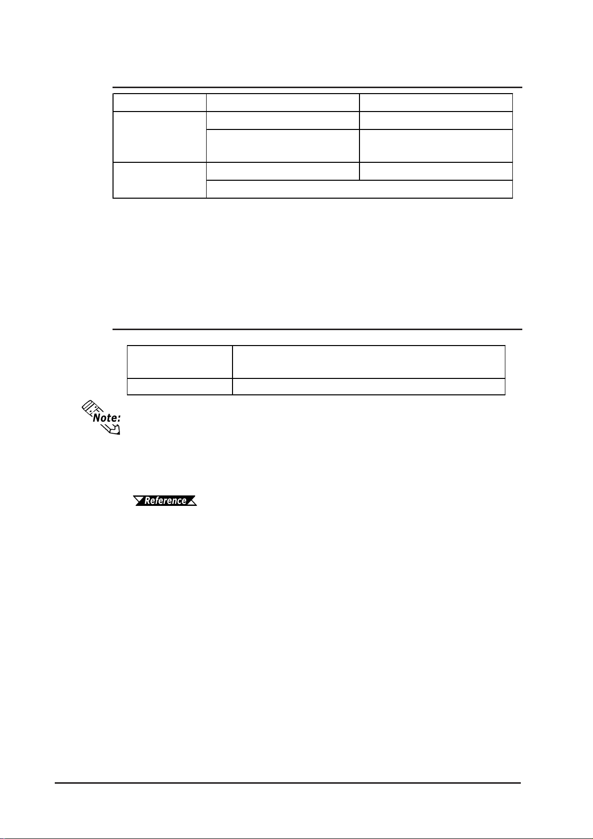
Application
[Approx. 640 screens at
GP-2300 Series GP-2301 Series
2MB FLASH EPROM 1MB FLASH EPROM
[Approx. 320 screens at
3.2KB/screen]
3.2KB/screen]
Da ta Ba c ku p
[us es a rechargeable lit hium bat t er y]
* 1 A Lithium battery's lifetime is:
10 years when the battery's ambient temperature is 40
4.1 years when the battery's ambient temperature is 50
1.5 years when the battery's ambient temperature is 60
*1
o
C or less.
o
C or less.
o
C or less.
When used for backup:(without main power)
Approximately 60 days, with a fully charged battery
Approximately 6 days, with a 10% charged battery
2.2.3 Touch Panel • Clock
256KB SRA M 128KB SRAM
Touch P ane l
Resolu ti on
Clock Accuracy ± 65 seconds/ month (at r oom temperature)
The GP's internal clock has a slight error. At normal operating temperatures and
conditions, with the GP operating from its lithium battery, the degree of error is 65
seconds per month. Variations in operating conditions and battery life can cause this
error to vary from -380 to +90 seconds per month. For systems where this degree
of error will be a problem, the user should be sure to monitor this error and make
adjustments when required.
16 x 12 k eys/screen
1 or 2 point pus h - s electable
Chapter 6.7 Set Up Time
2-4
GP-2300/2301 Series User Manual
Page 30
2.2.4 Interfaces
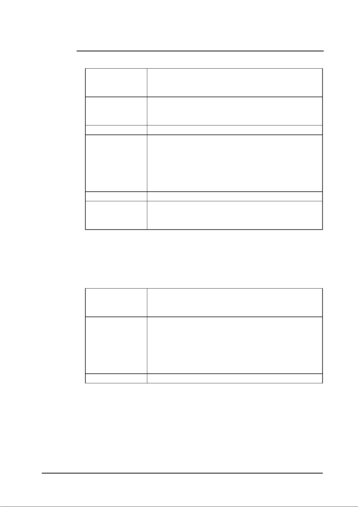
GP-2300 Series
Serial Interface
Expansion Seri al
Interface
Ethernet Interface
Tool Connector
CF Card Interface
Printer Interface
Chapter 2 - Specifications
Asynchronous Tra nsmiss ion : RS -23 2C/ RS - 422, Data Length: 7 or 8
bits, Stop Bit: 1 or 2 bits, Parity : None, Odd or Even, Data Transmission
Speed: 2, 400bps t o 115, 200bps
Asynchronous Transmission : RS - 232C, Dat a Lengt h: 7 or 8 bit s, Stop
Bit: 1 or 2 bits, Parity: None, Odd or Ev en, Data Transmission Speed:
2,400bps t o 38,400bps
IEEE802.3, 10BA SE-T
Asynchronous TTL level nonpr ocedural command I/F
<During screen file development >
Used for t rans f erring dat a t o and fr om the GP application softwar e and
the GP. Used f or dat a t ransfer with t he 2-P ort f eat ur e.
<During Operation>
Used for a variety of devices, including a bar-code reader.
1 slot
Compatible with NEC PC-PR201/PL , EPSON ESC/P24-J84(C),
HP Laser Jet PCL 4 command, EPSON PM/Stylus (6-color ink),
EPSON St ylus (4-color ink) compatible printers *1
*1 Printers with only Windows drivers cannot be used. However, certain types of
printers with both Windows and DOS drivers can be used. For details, contact
your local GP distributor.
GP-2301 Series
Asynchronous Tra nsmiss ion : RS -23 2C/ RS - 422, Data Length: 7 or 8
Serial Interface
Tool Connector
CF Card Interface
bits, Stop Bit: 1 or 2 bits, Parity : None, Odd or Even, Data Transmission
Speed: 2, 400bps t o 115, 200bps
Asynchronous TTL level nonpr ocedural command I/F
<During screen file development >
Used for t rans f erring dat a t o and fr om the GP application softwar e and
the GP. Used f or dat a t ransfer with t he 2-P ort f eat ur e.
<During Operation>
Used for a variety of devices, including a bar-code reader.
1 slot
GP-2300/2301 Series User Manual 2-5
Page 31
Chapter 2 - Specifications
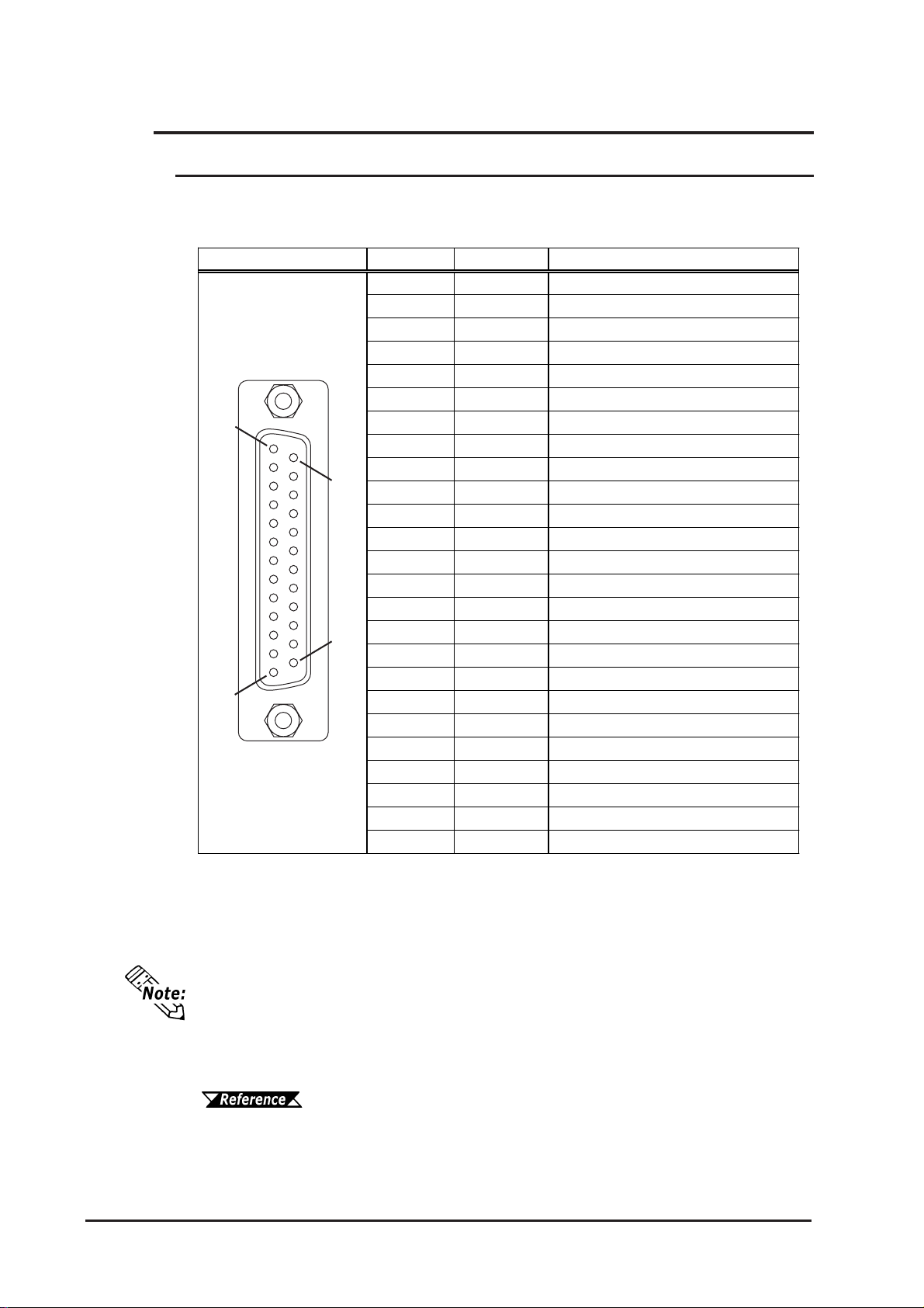
2.3 Interface Specifications
2.3.1 Serial Interfaces
This interface can be either RS-232C or RS-422. Connects GP to Host/PLC. (SocketT ype Connector)
Pin A s s ignme nts Pin # Signa l Na m e Condition
1
14
25
13
1 FG Frame ground
2 SD Send dat a ( RS - 232C)
3 RD Receive dat a ( RS - 232C)
4 RS Request s e nd ( RS - 232C)
5 CS Clear send (R S - 232C)
6 DR Data Set Ready (RS-232C)
7 SG Signa l gr oun d
8 CD Carrier detect (RS- 232C)
9 TRMX Termination (RS- 422)
10 RDA Receive data A (RS - 422)
11 SDA Send dat a A (RS-422)
12 NC No connection (Reserved)
13 NC No connection (Reserved)
14 VCC 5V± 5% out put 0. 25A
15 SDB Send dat a B ( RS -422 )
16 RDB Receiv e dat a B ( RS -422)
17 RI Ring Indicate (RS- 232C)
18 CSB Clear send B (RS -422)
19 ERB Enable receive B ( RS -422 )
20 ER Enable receive (RS-232C)
21 CSA Clear send A (RS-422)
22 ERA Enable receive A (RS-422)
23 NC No connection (Reserved)
24 NC No connection (Reserved)
25 NC No connection (Reserved)
2-6
Recommended Connector: Dsub25pin plug XM2A-2501<made by OMRON>
Recommended Cover: Dsub25pin cover XM2S-2511<made by OMRON>
Jack Screws: XM2Z-0071<made by OMRON>
• Use rough metric type M2.6x0.45 p threads used to secure the cable's set
screws.
Recommended Cable: CO-MA-VV-SB5PX 28AWG <made by HITACHI Cable
Ltd.>
• To confirm your PLC's connection specifications , refer to
GP-PRO/PBIII for Windows Device/PLC Connection Manual (in-
cluded with the screen creation software)
GP-2300/2301 Series User Manual
Page 32
Chapter 2 - Specifications
When creating your own cable, follow the instructions listed below:
<With RS-422>
• The following pairs of pin #'s must be connected to each other.
#18 (CSB) <—> #19 (ERB)
#21 (CSA) <—> #22 (ERA)
• When connecting the RS-422 cable and the #9 (TRMX) and #10 (RDA) points, a
termination resistance of 100
• When making a cable for a Memory Link system, be sure to use a 4-wire type.
<With RS-232C>
• Do not use the following pins: 9 (TRMX), 10 (RDA), 11 (SDA), 15 (SDB), 16
(RDB), 18 (CSB), 19 (ERB), 21 (CSA), 22 (ERA).
• The #1 (FG) terminal should only be connected if it is required by the device being
connected to.
• This unit’s serial port is not isolated, therefore, it is important that
you connect the SG (Signal Ground) terminals. If this is not done,
the RS422 circuit may be damaged.
ΩΩ
Ω is added between RDA and RDB.
ΩΩ
• Pin 14 (VCC) DC5V output is not protected. To prevent damage or
unit malfunction, be sure to use only the designated level of current.
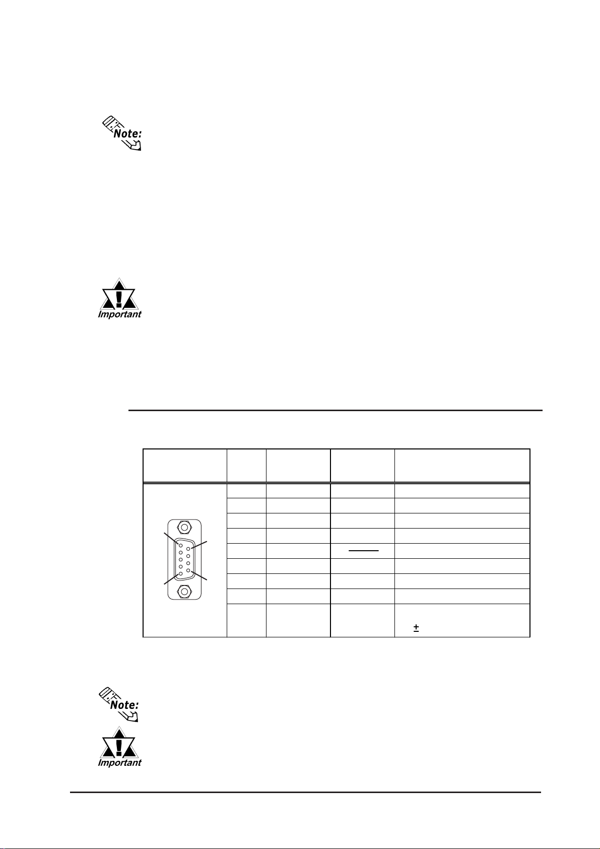
2.3.2 Expansion Serial Interface
This interface is used for RS-232C data transfer . The GP-2301 Series unit is not equipped
with this interface. (Plug-T ype Connector)
Pin A ss ignm e nts Pin No. Signal Nam e
1 CD I nput Carrier det ect (RS -232C)
2 RD Input Receive data (RS- 232C)
3 S D Output Send data (RS- 232C)
1
5
9
6
4 E R Output Enable r eceiv e (RS - 232C)
5 S G Signal Ground
6 DR Input Dat a Set Ready (RS-232C)
7 RS Output Request S e nd (R S - 232C)
8 CS Input Clear send (RS- 232C)
9 RI/VCC Input/Output
Signal
Condition
Directio n
Ring Indicate (RS-232C)
+5V 5% 0.25A
Recommended Connector: Dsub9pin socket XM2D-0901<made by OMRON>
Recommended Cover: Dsub9pin cover XM2S-0913<made by OMRON>
Jack Screws: XM2Z-0073<made by OMRON>
Use inch type screws (#4-40UNC) as set screws.
• Since Pin#9(RI/VCC) is unprotected, be sure to keep the output cur-
rent within the rated range.
• The GP-2301T does not have an expansion serial I/F.
GP-2300/2301 Series User Manual 2-7
Page 33
Chapter 2 - Specifications
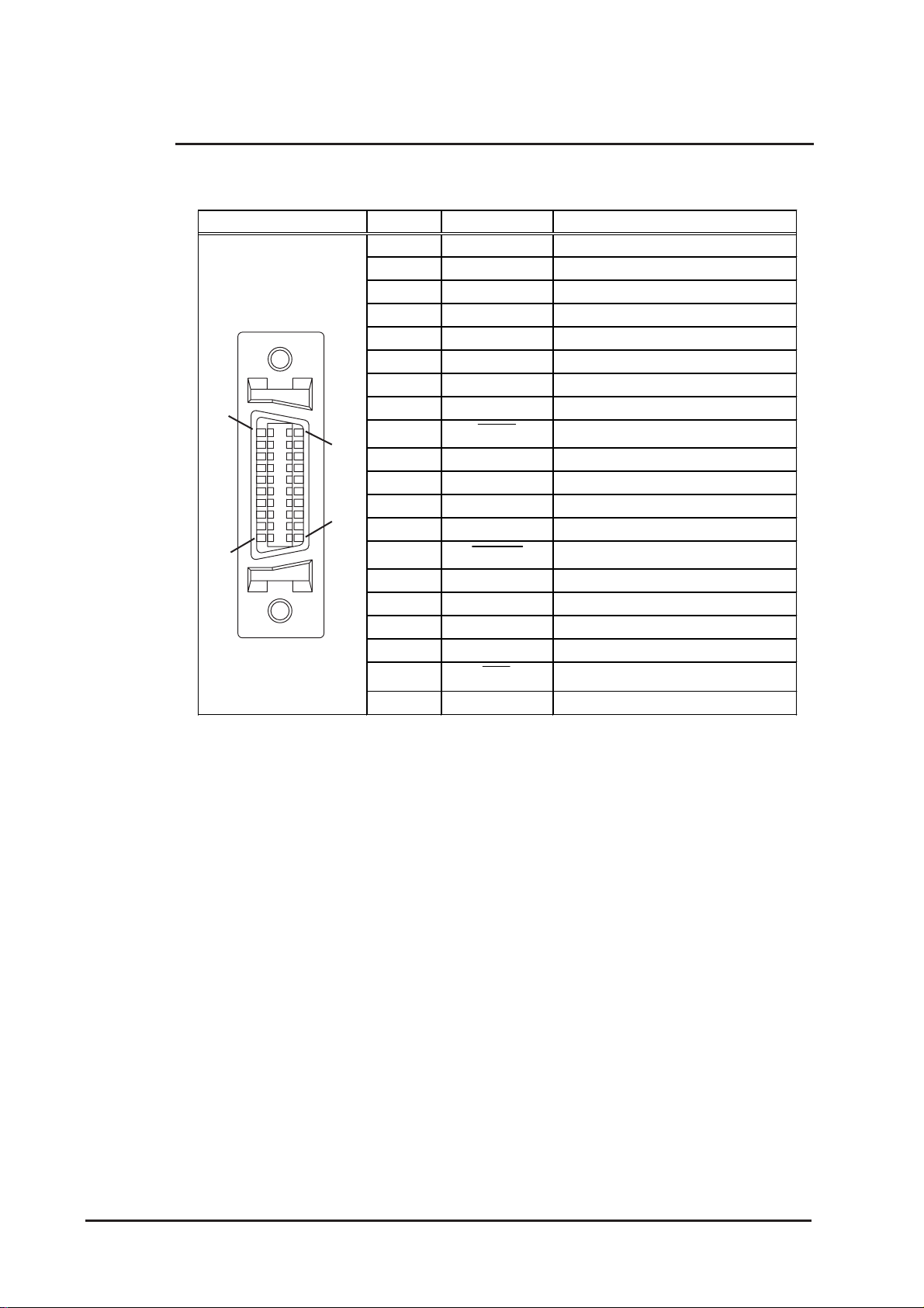
2.3.3 Printer Interface
When connecting a printer, use Digital’ s printer cable (PSM-PRCB00). The GP-2301
Series units are not equipped with this interface.
Pin A ss ignm e nts Pin # Signal N a m e Condition
1
11
20
10
1 GND Ground
2 RESERVE Reserved
3 PDB5 Data Signal
4 PDB4 Data Signal
5 PDB3 Data Signal
6 GND Ground
7SLCT
Select Status (Input)
*1
8 PDB0 Data Signal
9 P STB Strobe Signal (Output )
10 BUSY Bus y Signal (Input)
11 PDB7 Data Signal
12 PDB6 Data Signal
13 GND Ground
14
ERROR Print er Error (Input)
*1
15 GND Ground
16 PDB2 Data Signal
17 PDB1 Data Signal
18 PE
Paper Runout
*1
19 INIT Initialization Signal (Output)
20 GND Ground
* 1 Not used in the GP’s software.
2-8
GP-2300/2301 Series User Manual
Page 34
Chapter 2 - Specifications
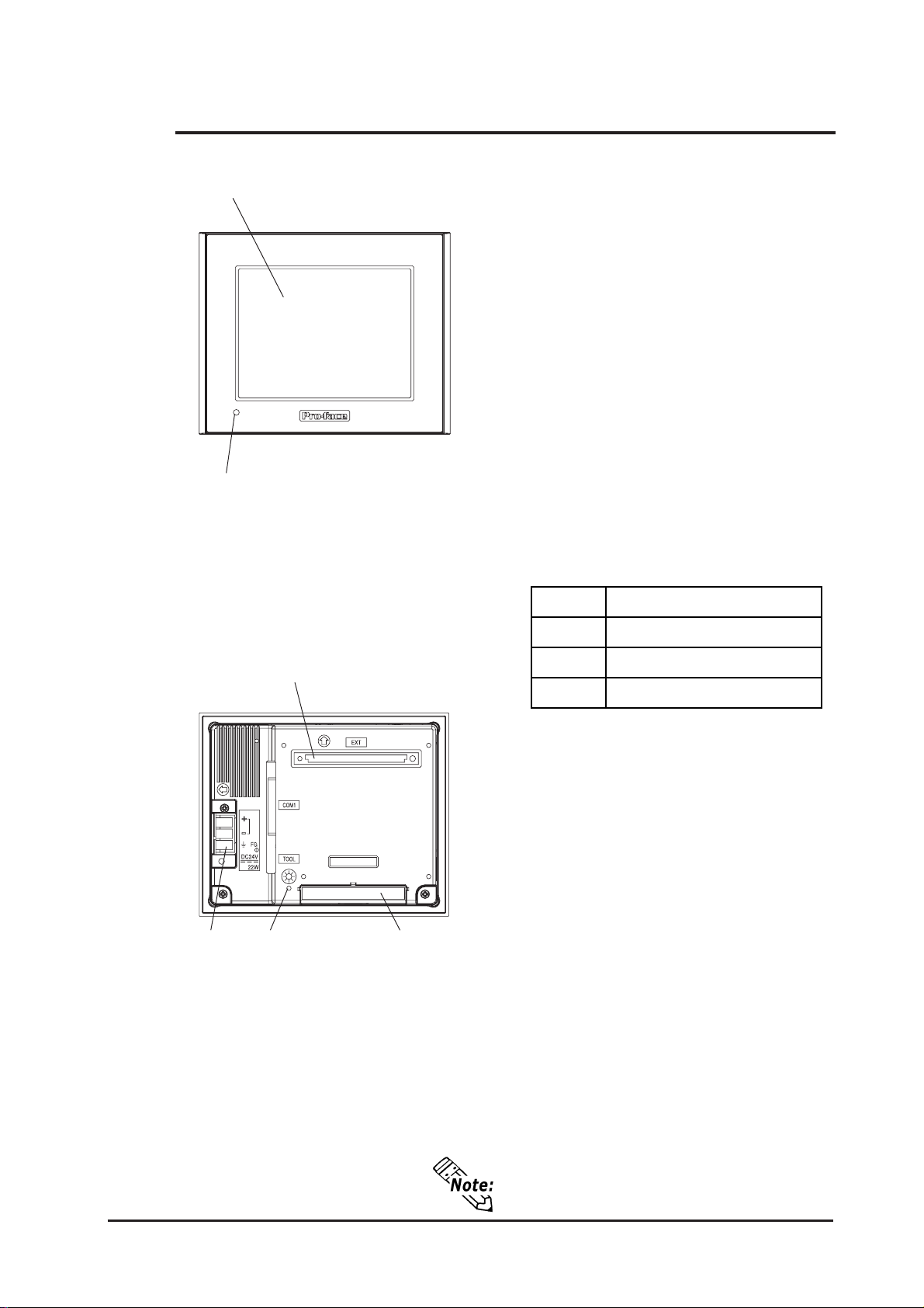
2.4 Part Names and Functions
A,B
C
Front
A:Display Panel
The GP monitor screen displays the screen
setup and corresponding host (PLC) data.
GP2300-LG41-24V .... Monochrome LCD
GP2300-SC41-24V .... STN Color LCD
GP2300-TC41-24V .... TFT Color LCD
GP2301-LG41-24V .... Monochrome LCD
GP2301-SC41-24V .... STN Color LCD
GP2301-TC41-24V .... TFT Color LCD
B: Touch Panel
Performs any screen change operations and
sends data to the PLC.
C:Status LED
This LED reflects the GP's condition.
Color Indicates
OFF
No power input
E
DF G
Rear
Green
Orange
Normal operation
Backligh t is bur n ed o ut
D:Power Input T erminal Block
Connects the power cord.
E: Expansion Unit I/F (EXT)
Connects expansion units with communication features.
F: CF Card Access Lamp
If the CF Card Cover is closed when the CF
Card is inserted, the LED lamp turns ON.
The LED lamp will remain turned ON even if
the CF Card Cover is opened while the GP
accesses the CF Card.
G:CF Card Cover
Open this cover to the CF Card Slot. When
accessing the CF Card, this cover must be
closed.
When accessing the CF Card, this cover
must be closed.
GP-2300/2301 Series User Manual 2-9
Page 35
Chapter 2 - Specifications
G
Bottom
H
I
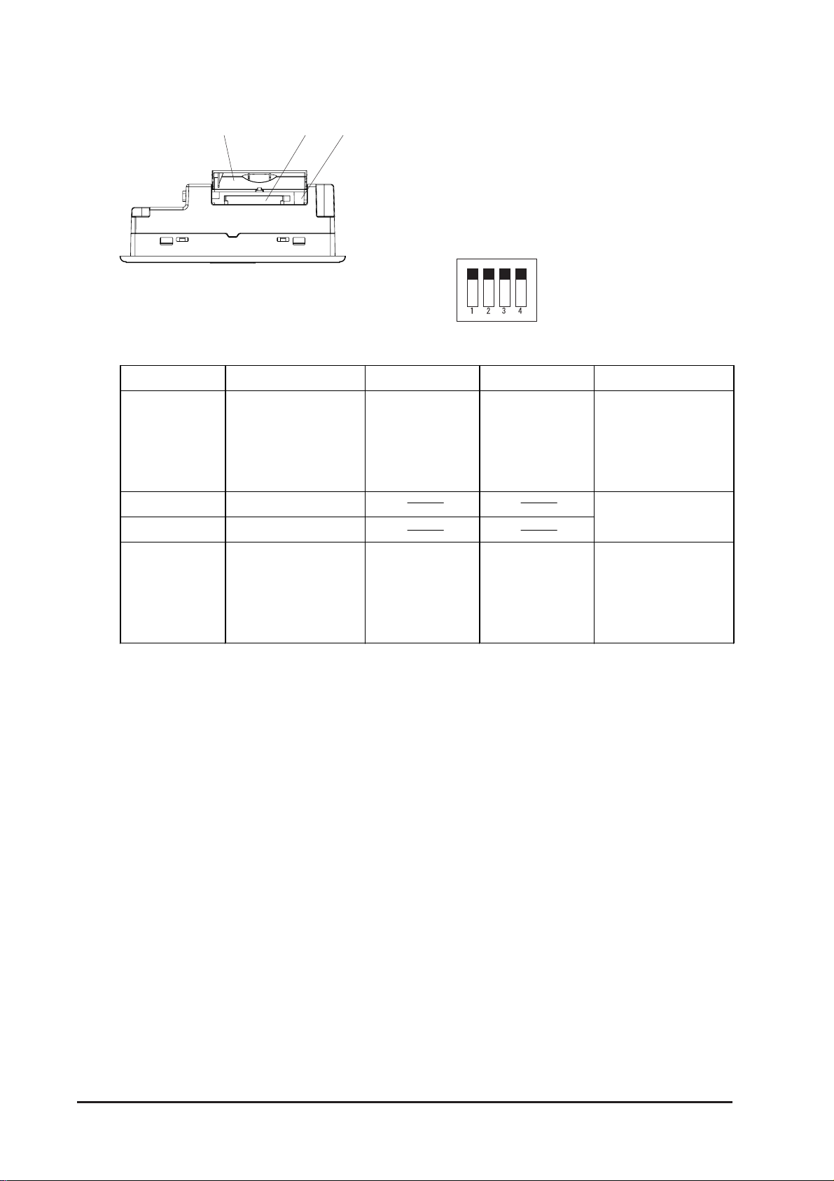
H:CF Card Slot
Insert the CF Card in this slot.
I: DIP Switches
The following chart explains the GP2300/
2301 units’ DIP switch parameters.
OFF
ON
Dip S witch Function ON OFF Note
This Di p sw itch
setti ng controls
Startup from
CF Card is
Startup from
CF Card is
CF Card with
startup data
1
the startup from a
enabled.
disabled.
required.
CF Card.
2 Reserved
3 Reserved
Keep these
swi tches OFF
This setting
controls the forced
Forc e d c lose
enabled.
Forc e d c lose
disabled.
Used when CF
Card cover i s
4
cl osing of t he CF
damaged.
Card cover.
2-10
GP-2300/2301 Series User Manual
Page 36
Chapter 2 - Specifications
J
K
L
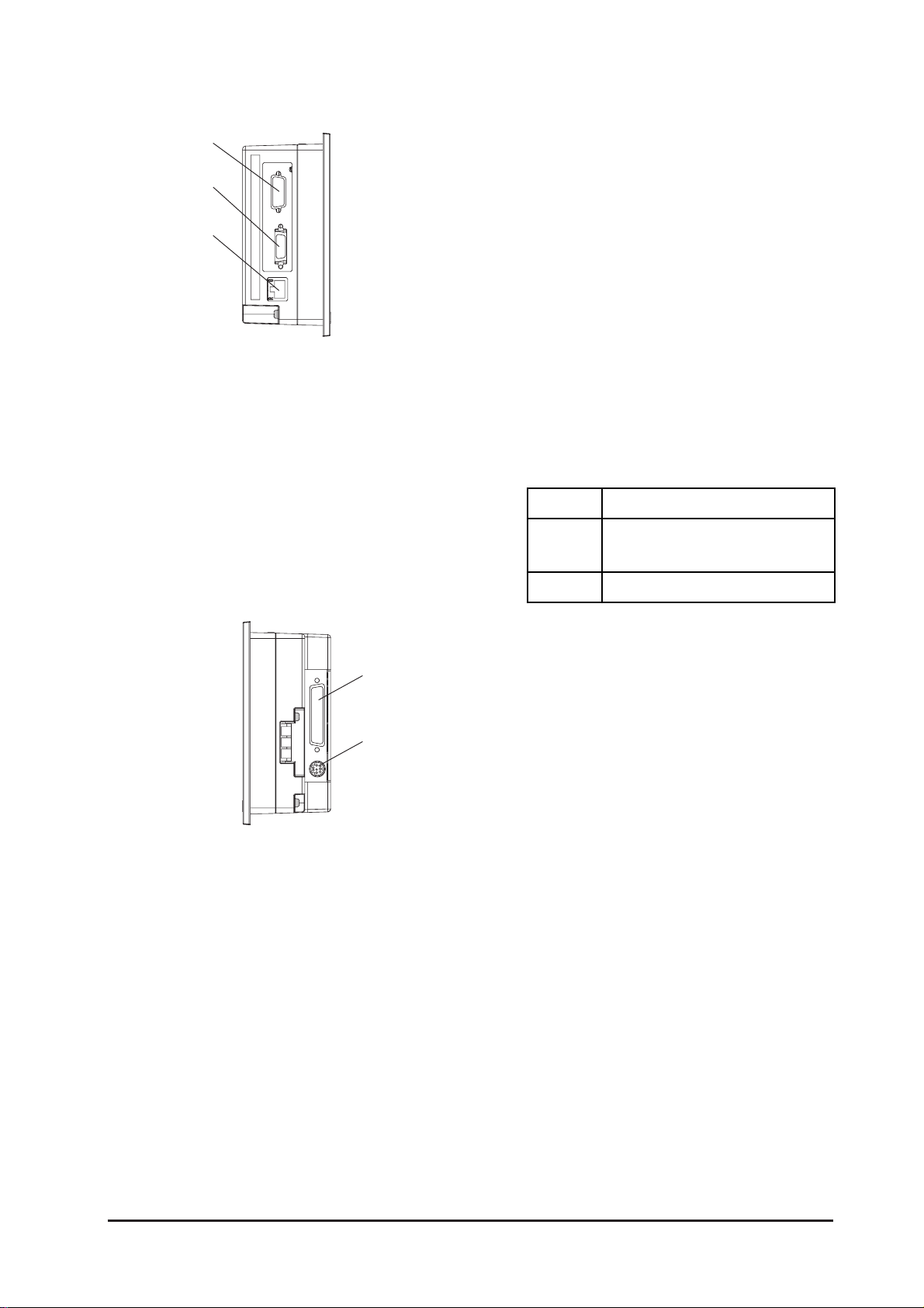
Left
(GP-2300 Series Unit)
J: Expansion Serial Interface (COM2)
Uses Dsub9 pin’s RS-232C cable.
(GP-2300 Series units only .)
K:Printer Interface (PRINT)
Connect the printer cable here. Recommended cable: Digital Electronic Corporation
PSM-PRCB00 Cable.
(GP-2300 Series units only .)
L: Ethernet Interface (10BASE-T)
The LED will change (turn ON, blink) according to the communication status.
(GP-2300 Series units only .)
Color Indicates
Orange
Green
Blinks dur ing dat a t r ans f er /
Turns ON when power ON.
Turns ON when linked.
Right
M
N
M:Serial Interface (COM1)
Used for the Dsub25 pin’ s RS-232C and RS422 cables. Is connected to the Host (PLC.)
N:Tool Connector (T OOL)
The Data Transfer cable, or Bar Code Reader
can be connected here.
GP-2300/2301 Series User Manual 2-11
Page 37
Chapter 2 - Specifications
2.5 Dimensions
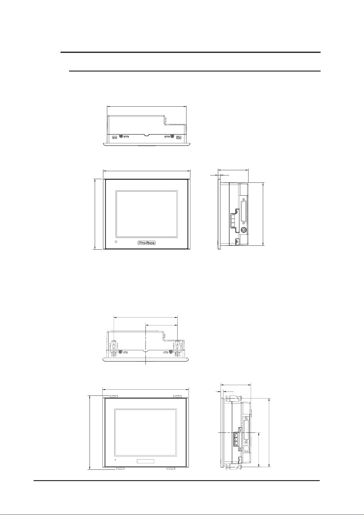
2.5.1 GP-2300/2301 Series External Dimensions
Unit: mm [in.]
138 [5.43]
Top
155.5 [6.12]
Front
171 [6.73]
Right
60 [2.36]
5 [0.2]
123 [4.84]
The following drawing shows the GP-2300 Series unit with installation fasteners.
Unit: mm [in.]
Top
126 [4.96]
63 [2.48]
Right
146 [5.75]
Front
171 [6.73]
5 [0.2]
60 [2.36]
136 [5.35]
2-12
68 [2.68]
GP-2300/2301 Series User Manual
Page 38
Chapter 2 - Specifications
C
CO
C
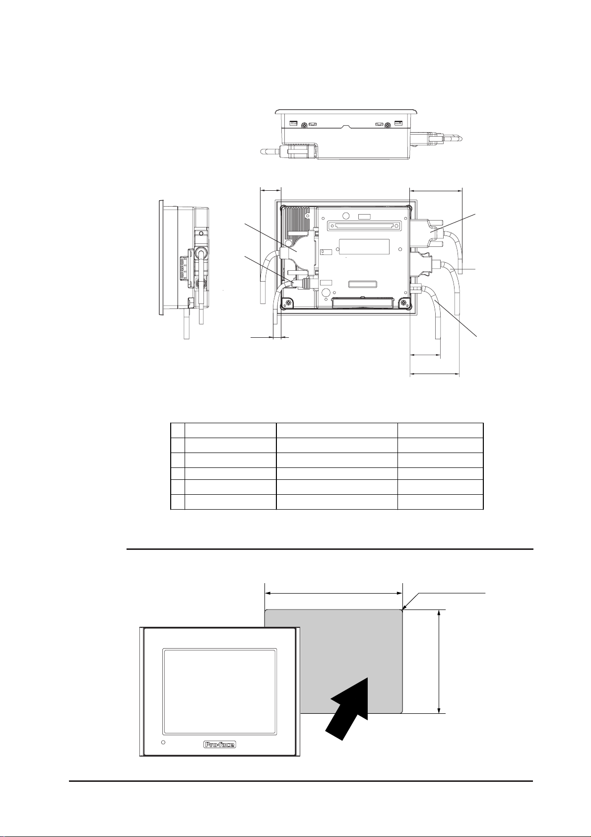
The following drawing shows the GP-2300 Series unit with cables.
Unit: mm [in.]
Top
24 [0.94]
A
B
9 [0.35]
BackLeft
61 [2.40]
C
D
E
35 [1.38]
58 [2.28]
The dimensions given here are for the cables in the following chart. Use the values for
reference when designing the enclosure for the GP .
Interface Cable Model
A COM1 Multi Link Cable GP230-I S12 -0
B TOOL Tr ans f er Ca ble GPW-CB 02
M2 RC-232C Cable
D PRINTER Printer Cable PSM-PRCB00
E 10BASE-T Ethernet 10BASE-T Ethernet Cable Commercial Type
ommercial Type
2.5.2 Panel Cut Dimensions
Unit: mm [in.]
GP-2300/2301 Series User Manual 2-13
156
+1
[6.14 ]
0
+0.04
0
under 4-R3
+0.04
0
[4.86 ]
+1
0
123.5
Page 39
Chapter 2 - Specifications
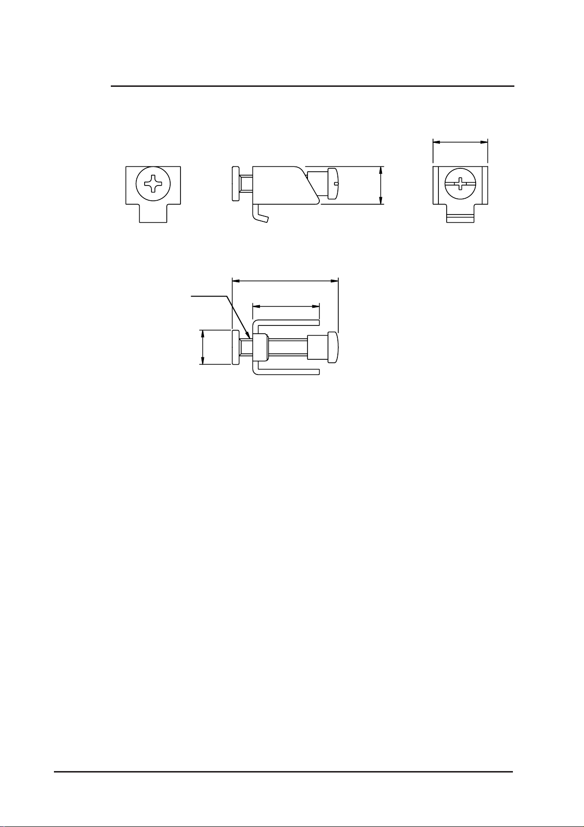
2.5.3 Installation Fasteners
Unit: mm [in.]
16 [0.63]
11 [0.43]
31 [1.22]
19.5 [0.77]
10 [0.39]
2-14
GP-2300/2301 Series User Manual
Page 40
Chapter
3 Installation and Wiring
3.1 Installation
3.1.1 Installation Procedures
Follow the steps given below when installing the GP .
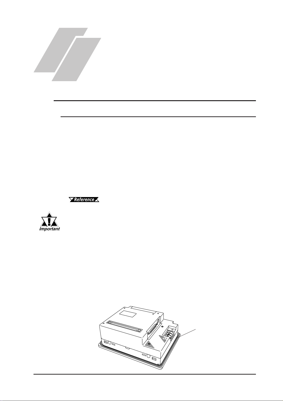
Check the Installation Gasket’s Seating
It is strongly recommended that you use the installation gasket, since it absorbs vibration
in addition to repelling water .
Place the GP on a level surface with the display panel facing downward. Check that the
GP’ s installation gasket is seated securely into the gasket’s groove, which runs around
the perimeter of the panel’ s frame.
1. Installation
2. Wiring Precautions
3. Tool Connector
4. Ethernet Cable Connector
5. CF Card Insertion and Removal
For details about installing the gasket, refer to
8.1.2 Installation Gasket Check/Replacement
• Before installing the GP into a cabinet or panel, check that the installation gasket is securely attached to the unit.
• A gasket which has been used for a long period of time may have
scraches or dirt on it, and could have lost much of its dust and drip
resistance. Be sure to change the gasket periodically (or when
scratches or dirt become visible).
• Be sure to use gasket model PS300-WP00.
• Be sure the gasket's seam is not inserted into any of the unit's corners, only in the straight sections of the groove. Inserting it into a
corner may lead to its eventually tearing.
GP
Rear face
Installation
Gasket
GP-2300/2301 Series User Manual
3-1
Page 41
Chapter 3 - Installation and Wiring
Creating a Panel Cut
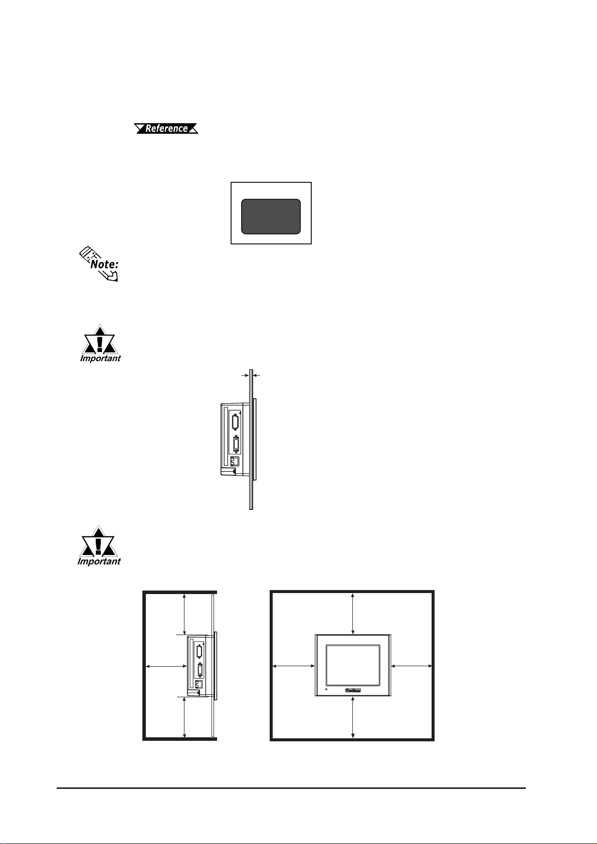
Create the correct sized opening required to install the GP , using the installation dimensions given.
2.5.2 Panel Cut Dimensions
The installation gasket, installation brackets and attachment screws are all required when
installing the GP .
Panel
Panel Cut
Area
Check that the installation panel or cabinet's surface is flat, in good condition and
has no jagged edges. Also, if desired, metal reinforcing strips can be attached to
the inside of the panel, near the Panel Cut, to increase the panel’s strength.
Panel thickness should be from 1.6mm [0.06in.] to 10mm [0.4in.]. Decide
the panel’s thickness based on the level of panel strength required.
1.6mm [0.06in.] to 5mm [0.2in.]
For easier maintenance, operation, and improved ventilation, be sure to
install the GP at least 100 mm [3.94 in.] away from adjacent structures
and other equipment.
100
[3.94]
100[3.94]
3-2
100[3.94]
100
[3.94]
100[3.94]
100[3.94]
100[3.94]
GP-2300/2301 Series User Manual
Page 42
Chapter 3 - Installation and Wiring
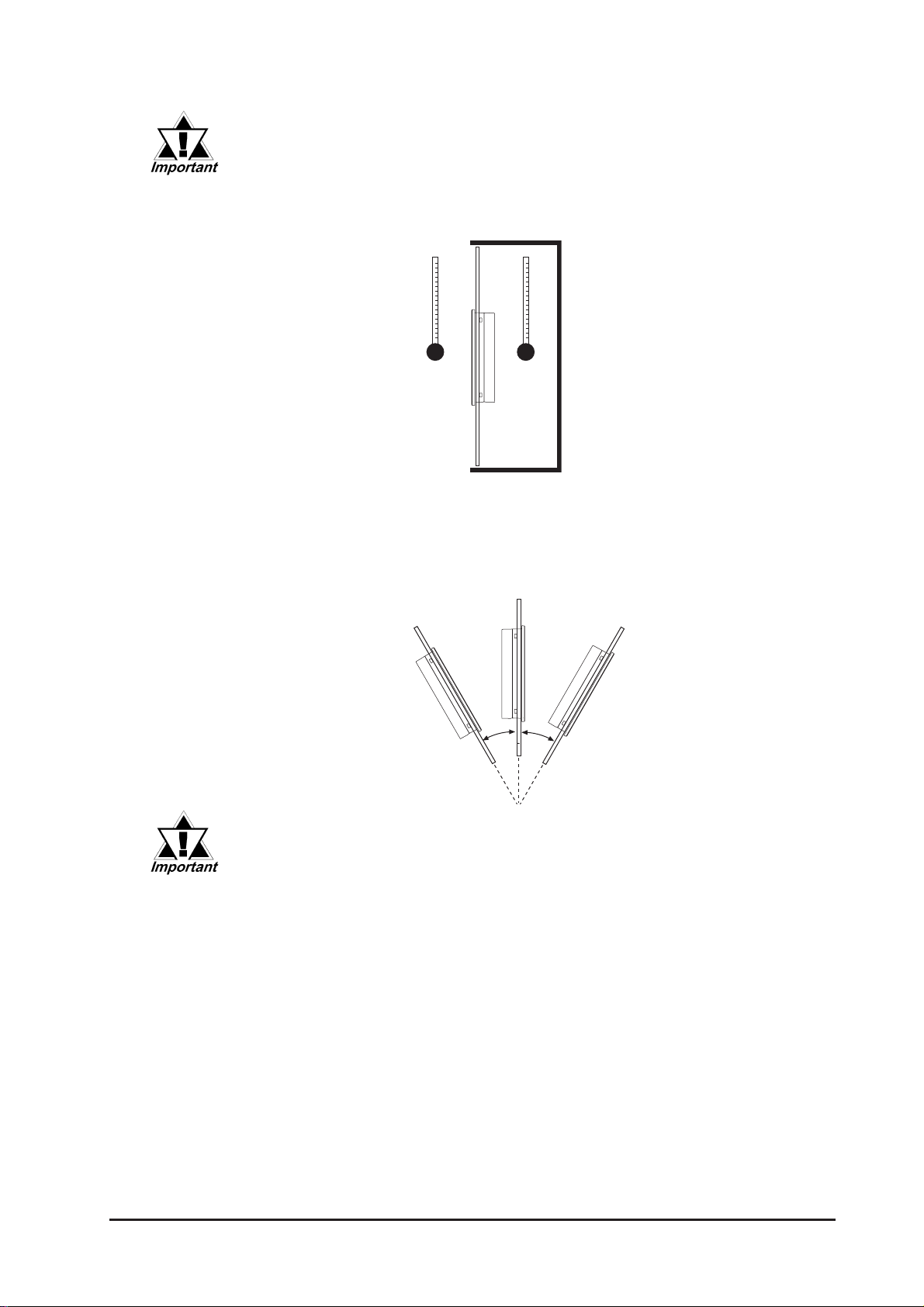
• Be sure that the ambient operation temperature and the ambient humidity are within their designated ranges. (When installing the GP in a
cabinet or enclosure, the term “ambient operation temperature” indicates the cabinet or enclosure’s internal temperature.
Outside
Cabinet
Inside
Cabinet
• Be sure that heat from surrounding equipment does not cause the GP
to exceed its standard operating temperature.
• When installing the GP in a slanted panel, the panel face should not
incline more than 30o.
30O or less
• When installing the GP in a slanted panel, and the panel face inclines
more than 30o, the ambient temperature must not exceed 40 oC. You
may need to use forced air cooling (fan, A/C) to ensure the ambient
operating temperature is 40 oC or below.
• When installing the GP vertically, position the unit so that the Power
Input Terminal Block is also vertical.
GP-2300/2301 Series User Manual
3-3
Page 43
Chapter 3 - Installation and Wiring
Installing the GP
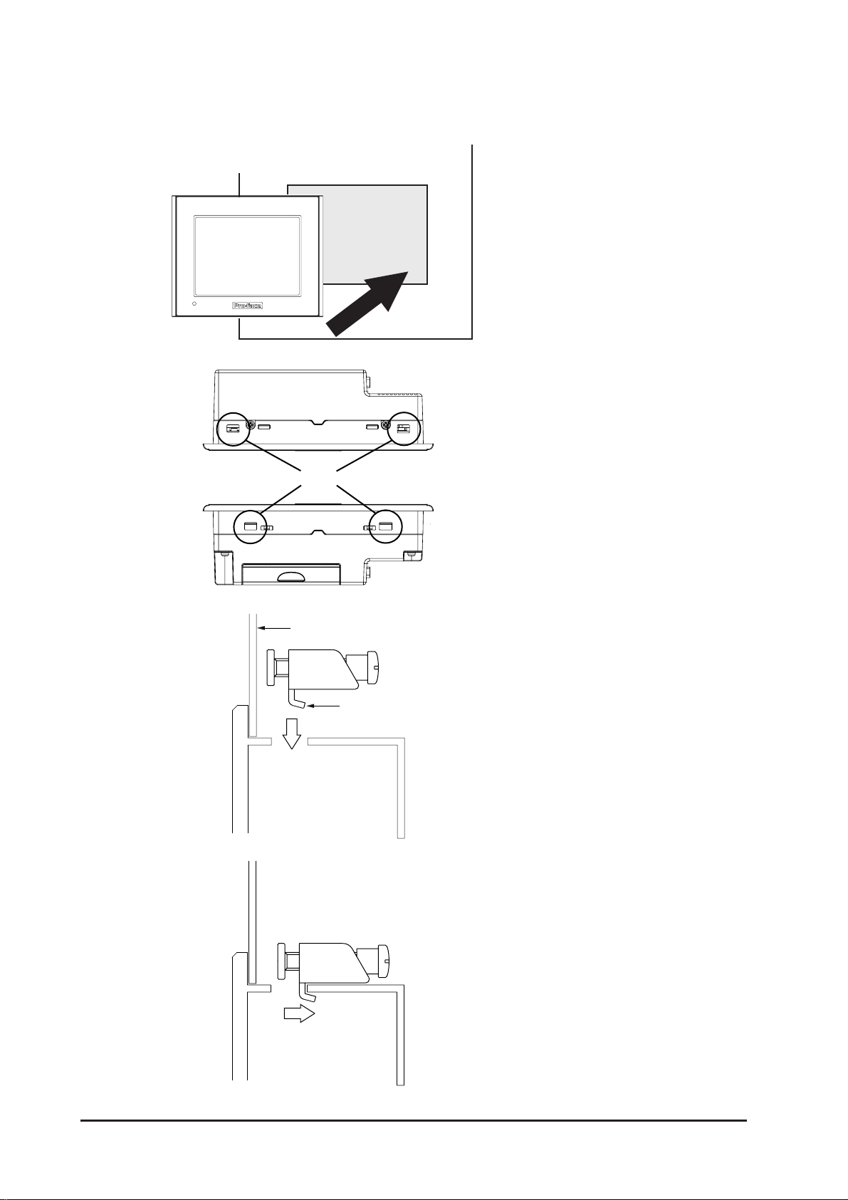
1) Insert the GP into the panel cut
out, as shown here.
2) Insert the installation fasteners
into the GP’s insertion slots, at
the top and bottom of the unit.
Slots
Installation Panel
Hook
(total: 4 slots)
3) Insert each of the fasteners
shown below . Be sure to pull
the fastener back until it is flush
with the rear of the attachment
hole.
3-4
GP-2300/2301 Series User Manual
Page 44
Chapter 3 - Installation and Wiring
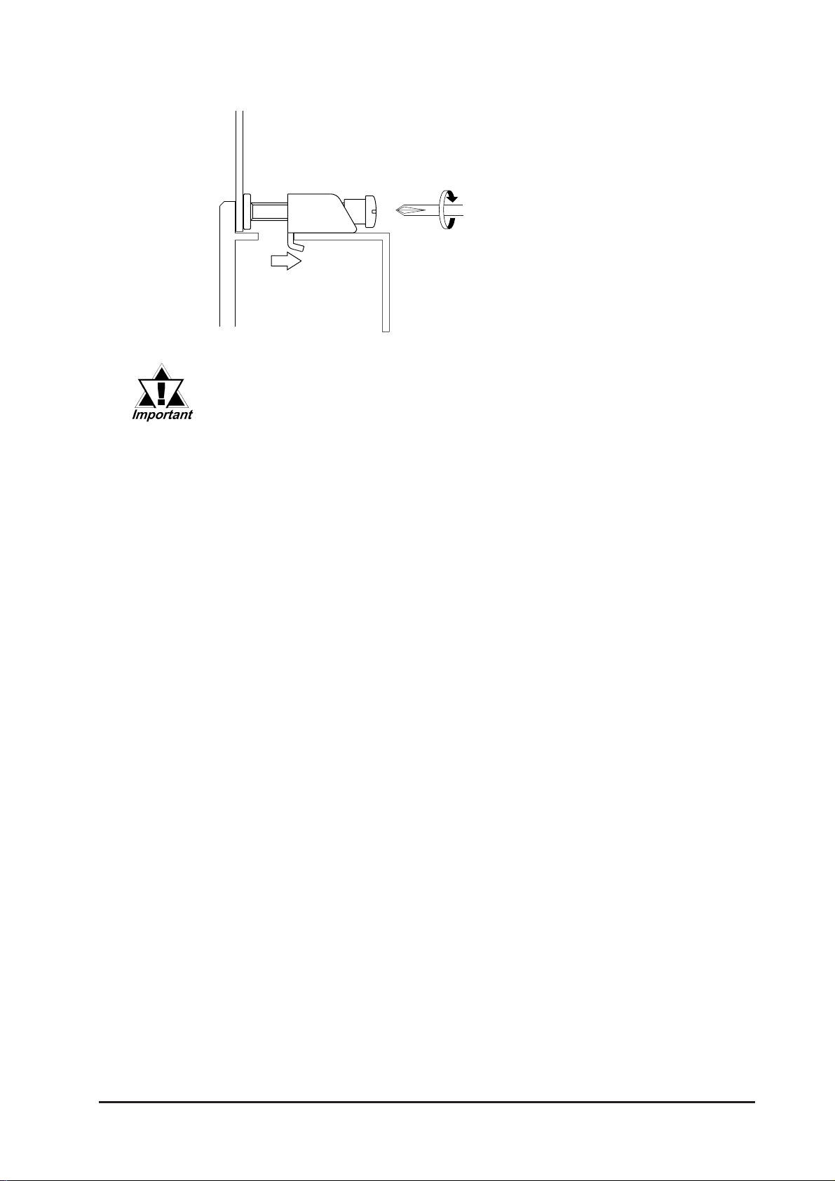
4) Use a Phillips screwdriver to
tighten each fastener screw and
secure the GP in place.
A torque of only 0.5 N•m is sufficient to tighten these screws. Do not
use too much force, since it may damage the GP unit.
GP-2300/2301 Series User Manual
3-5
Page 45
Chapter 3 - Installation and Wiring
3.2 Wiring Precautions
3.2.1 Connecting the Power Cord
WARNINGS
• To avoid an electric shock, be sure the power cord is
unplugged from the power outlet when connecting
the power terminals to the GP unit.
• The GP2300-LG41-24V/GP2300-SC41-24V/GP2300TC41-24V and GP2301-LG41-24V/GP2301-SC41-24V/
GP2301-TC41-24V are designed to use only DC24V
power. Using any other level of power can damage
both the power supply and the GP unit.
• Since the GP is not equipped with the power switch,
be sure to connect a breaker type power switch to the
GP’s power cord.
• Be sure to ground the GP’s FG terminal. Failure to do
so can lead to an electrical shock or GP malfunction.
• To prevent the Ring Terminals from causing a short when the terminal block attachment screws are loosened, be sure to use sleeve-type
Ring Terminals.
• When the FG terminal is connected, be sure the wire is grounded. Not
grounding the GP unit will result in excessive noise. Use your country’s
applicable standard for grounding.
3.2.3 Grounding
• The SG and FG terminals are connected internally in the GP unit.
• When connecting the SG line to another device, be sure that the design of the system/connection does not produce a shorting loop.
• Wherever possible, use thick wires (max 2mm2) for power terminals, and twist
the exposed wire ends when connecting the Ring Terminals.
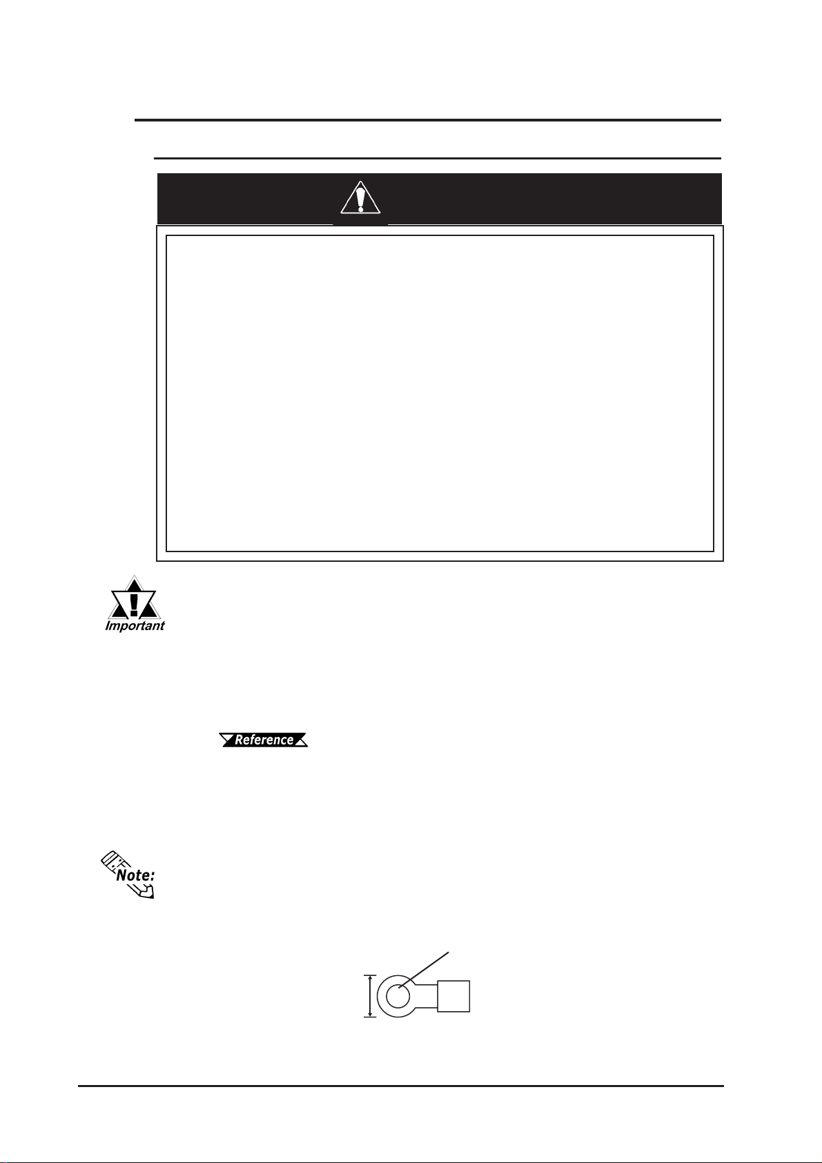
• Please use the following size crimp-on type Ring Terminals.
3-6
Under 6.0mm[0.24in.]
φφ
Over
φ3.2mm[0.13in.]
φφ
GP-2300/2301 Series User Manual
Page 46
Chapter 3 - Installation and Wiring
Connecting the Power Supply Terminals
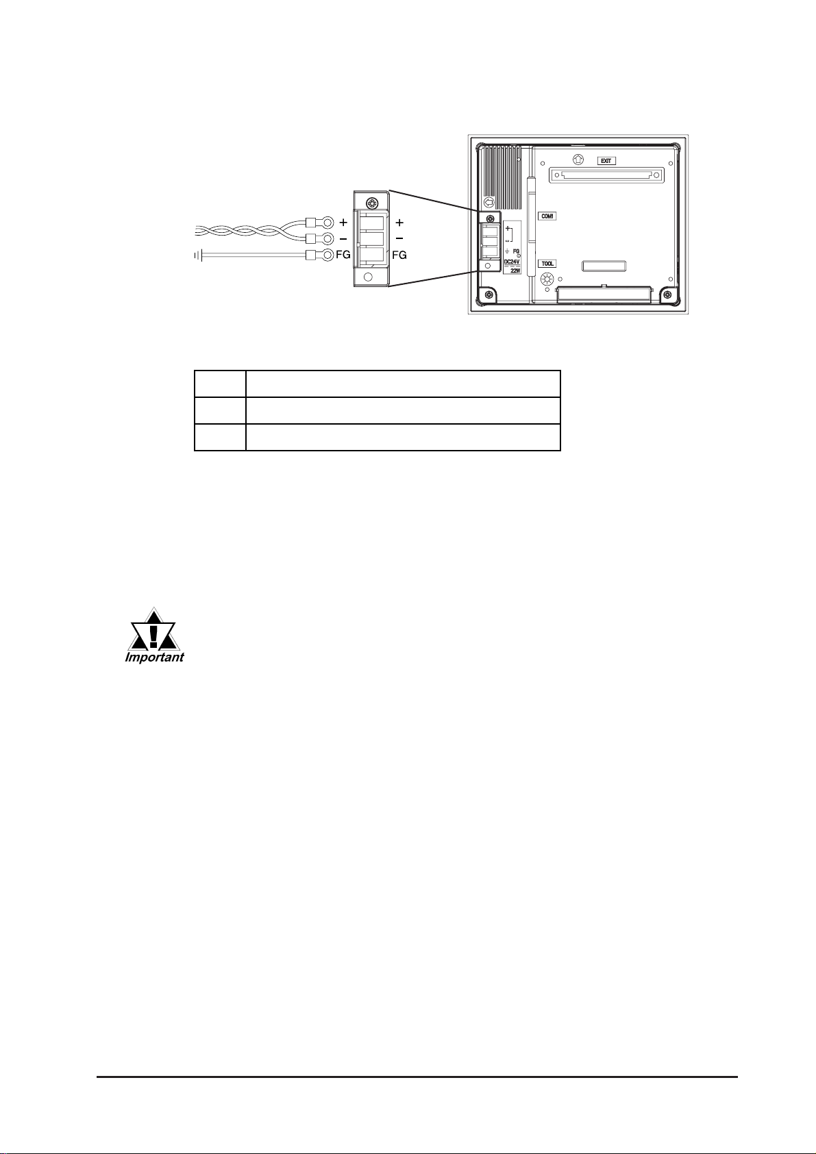
Power
Terminal
Block
Posit ive Line
+
Negative Line
–
Grounding Terminal connected to t he GP chassis
FG
1) Be sure that the GP's power cord is not plugged in to the power supply.
2) Remove the Terminal Strip's clear plastic cover .
3) Remove the screws from the three (3) middle terminals, position the Ring Terminals
as shown above and reattach the screws.
4) Reattach the T erminal Strip's clear plastic cover.
• Check each wire to make sure the connections are correct.
• A torque of only 0.5 to 0.6 N•m is required to tighten an attachment
screw.
GP-2300/2301 Series User Manual
3-7
Page 47
Chapter 3 - Installation and Wiring
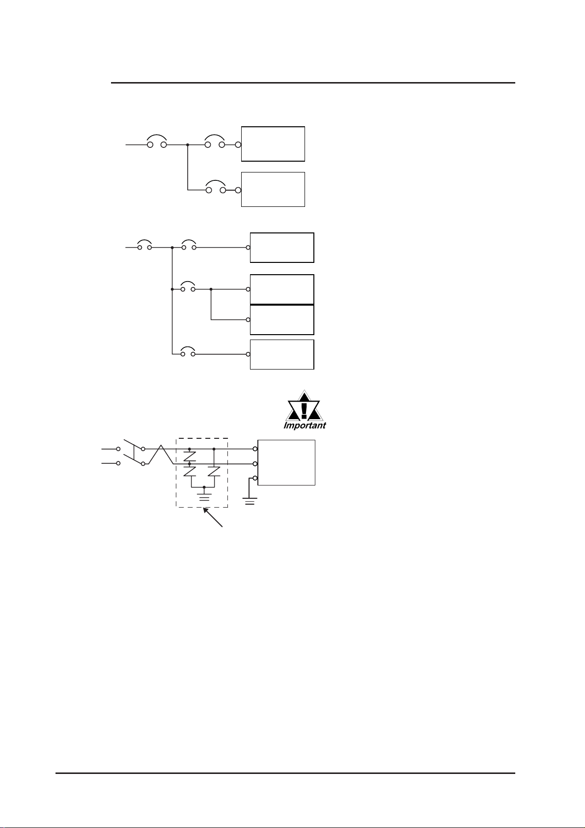
3.2.2 Connecting the Power Supply
Main
Power
Main
PowerGPPower
Power
Input/Output
Main
Circuit
GP
Power
Motor
GP Unit
Input/Output
Unit
GP Unit
Input/Output
Power
Input/Output
Power
Operation
Unit
• When supplying power to the GP
unit, please separate the input/output
and operation unit lines, as shown.
• T o increase the noise resistance
quality of the power cable, simply
twist each power wire before
attaching the Ring Terminal.
• The power supply cable must not be
bundled or positioned close to main
circuit lines (high voltage, high
current), or input/output signal lines.
• Connect a lightning surge absorber ,
as shown in the diagram, to deal with
power surges.
• T o avoid excess noise, make the
power cable as short as possible.
E1
Lightning
Surge
Absorber
GP Unit
FG
E2
• Be sure to ground the surge
absorber (E1) separately from
the GP unit (E2).
• Select a surge absorber that
has a maximum circuit voltage
greater than that of the peak
voltage of the power supply.
3-8
GP-2300/2301 Series User Manual
Page 48
Chapter 3 - Installation and Wiring
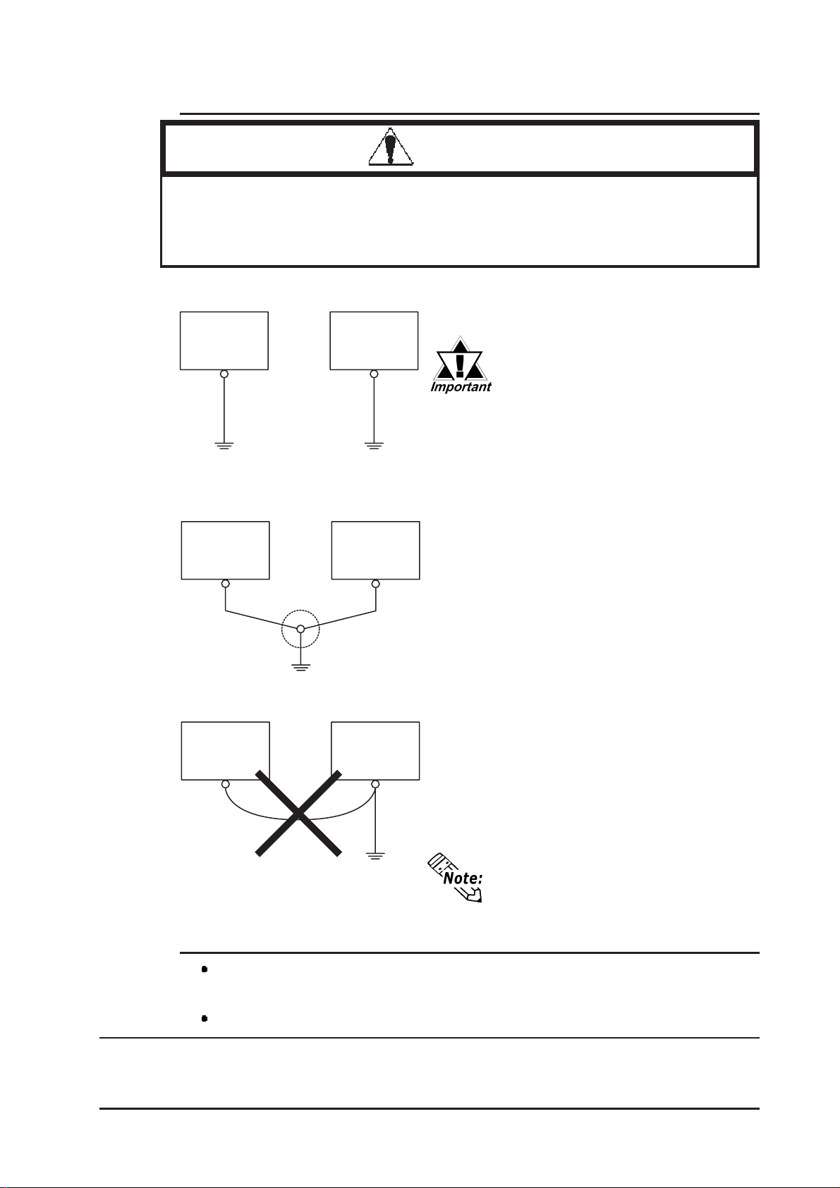
3.2.3 Grounding
CAUTION
Do not use common grounding, since it can lead to an
accident or machine breakdown.
(a) Exclusive Grounding (BEST)
GP Unit
(b) Common Grounding (OK)
GP Unit
(c) Common Grounding (Not OK)
GP Unit
Other
Equipment
*1
Other
Equipment
Other
Equipment
*1
Connect the FG terminal found at the back of
the GP to an exclusive ground. [diagram (a)].
• Check that the grounding resistance is less than 100
ΩΩ
Ω
ΩΩ
.
• FG and SG terminals are internally connected in the GP.
• When connecting the SG line to
another device, be sure that the
design of the system/connection does not produce a shorting loop.
• The grounding wire should have
a cross sectional area greater
than 2mm2. Create the connection point as close to the GP unit
as possible, and make the wire
as short, as possible. When using a long grounding wire, replace the thin wire with a thicker
wire, and place it in a duct.
3.2.4 I/O Signal Line Placement
Input and output signal lines must be separated from the power control cables for
operating circuits.
If this is not possible, use a shielded cable and connect the shield to the GP's frame.
*1 Use a grounding resistance of less than 100
wire, or your country’s applicable standard. For details, contact your local GP
distributor.
GP-2300/2301 Series User Manual
If exclusive grounding is not possible, use a
common connection point. [diagram (b)]
If the equipment does not function
properly when grounded, disconnect
the ground wire from the FG terminal.
Ω
and a 2mm2 or greater thickness
3-9
Page 49
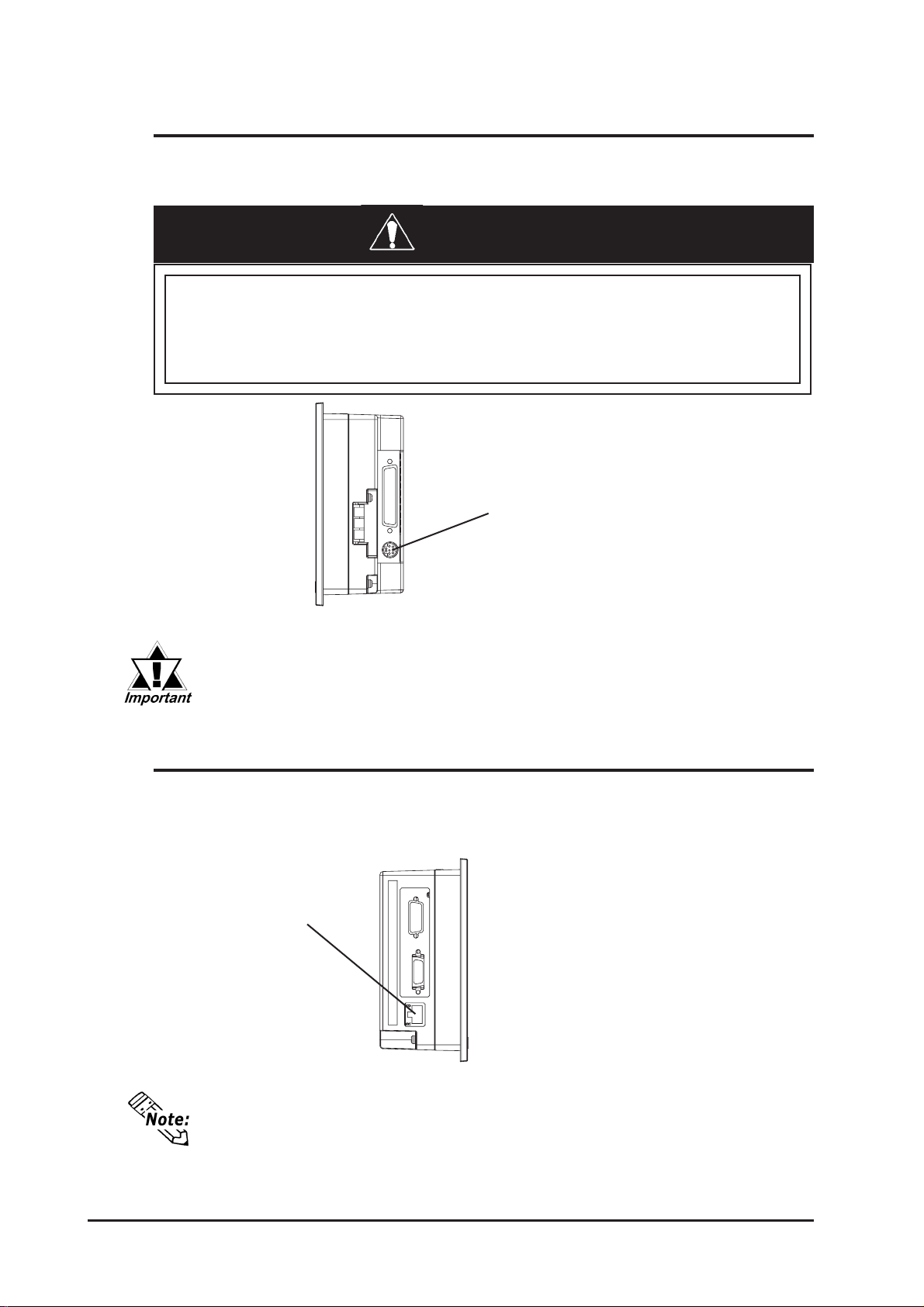
Chapter 3 - Installation and Wiring
3.3 Tool Connector
The GP's Data Transfer Cable, Memory Loader , or the Bar Code Reader can be
attached to the GP unit’s T ool Connector .
WARNING
To prevent an electric shock, unplug the GP unit's power
cord from the main power supply prior to attaching or
detaching any connector(s) to or from the GP.
T ool Connector
Right Face
When the Bar Code Reader uses a separate power supply:
• Turn the Bar Code Reader ON before turning the GP ON.
• Turn the GP OFF before turning the Bar Code Reader OFF.
3.4 Ethernet Cable Connector
Use the following drawing to locate your GP unit’s Ethernet connector . The GP Ethernet
interface is IEEE802.3 compatible, and transmits data at 10Mbps. (The Ethernet I/F is
not equipped on the GP2301 Series.)
Ethernet Interface
(10BASE-T)
3-10
Left Face
(GP-2300 Series unit)
• It is strongly recommended that your Ethernet network is installed by a trained
engineer.
• 1:1 connections using a cross cable may not be possible depending on
the type of personal computer and network card you are using. Make sure to
use a hub for connection.
GP-2300/2301 Series User Manual
Page 50
Chapter 3 - Installation and Wiring
3.5 CF Card Insertion and Removal
CAUTIONS
When using the GP Unit and a CF Card, follow the precautions below:
• Prior to inserting or removing a CF Card, be sure to turn
the GP unit’s CF Card ACCESS switch OFF and to confirm
that the ACCESS lamp is not lit. If you do not, CF Card
internal data may be damaged or lost.
• While a CF Card is being accessed, NEVER turn OFF or
reset the GP, or insert or remove the CF Card. Prior to
performing these operations, create and use a special GP
application screen that will prevent access to the CF Card.
Refer to GP-PRO/PB III for Windows Tag Reference Manual (in-
cluded in the screen editor software package)
• Prior to inserting a CF Card, familiarize yourself with the
CF Card’s front and rear face orientation, as well as the CF
Card
positioned when it is inserted into the Mulit Unit, the CF
Card’s internal data and the GP unit may be damaged or
broken.
• Be sure to use only CF Cards manufactured by the Digital
Electronics Corporation. The CF Card’s internal data may
be damaged when using another manufacturer’s CF Card.
• Once GP data is lost, it cannot be recovered. Since accidental data loss can occur at any time, be sure to back up
all GP screen and CF Card data regularly.
• Be sure to follow the instructions given below to prevent
the CF Card's internal data from being destroyed or a CF
Card malfunction from occuring:
• DO NOT bend the CF Card.
connector’s position. If the CF Card is not correctly
• DO NOT drop or strike the CF Card against another
object.
• Keep the CF Card dry.
• DO NOT touch the CF Card connectors.
• DO NOT disassemble or modify the CF Card.
GP-2300/2301 Series User Manual
3-11
Page 51
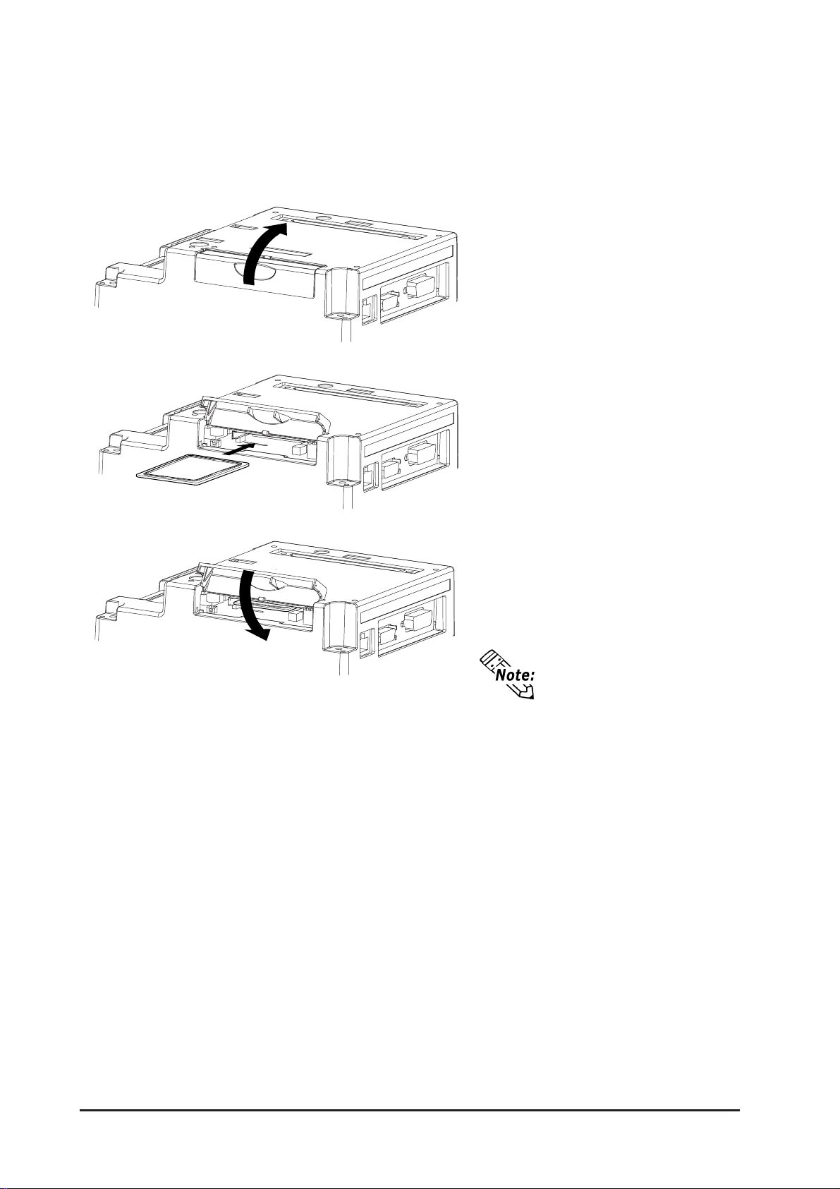
Chapter 3 - Installation and Wiring
Inserting the CF Card
Use the following steps to insert the CF Card in the GP .
1) Open the CF Card Cover upward.
2) Insert the CF Card in the CF Card
Slot, until the eject button is pushed
forward.
3) Close the cover. (As shown.)
4) Confirm that the CF Card Access
LED turns ON.
The GP cannot access the
CF Card if the CF Card
cover is already opened. If
however, the CF Card
Cover is opened while the
GP is accessing the CF
Card, access will not be
interrupted.
3-12
GP-2300/2301 Series User Manual
Page 52
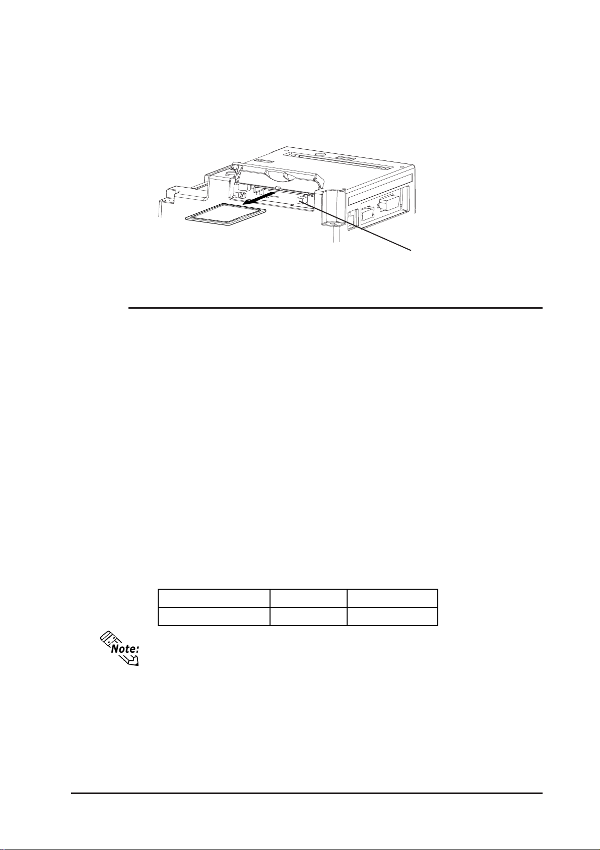
Chapter 3 - Installation and Wiring
Removing the CF Card
Simply reverse the steps shown in the previous “Inserting CF Card” explanation. Prior to
depressing the eject button to remove the CF Card, confirm that the CF Card Access LED
is turned OFF .
Eject Button
3.5.1 CF Card Handling
The CF Card has a data overwrite limit of approximately 100,000 times. Therefore, be
sure to back up all CF Card data regularly to another storage media. (100,000 times
assumes the overwriting of 500KB of data in DOS format)
T wo methods are available for backing up data. After using either method (1) or method
(2), use your PC to save your data to the CF Card.
(1) If your PC is equipped with a PC Card Slot
T o view CF Card data on a personal computer , first, insert the CF Card into a CF Card
Adapter .
(2) If your PC is NOT equipped with a PC Card slot
Use a commercially available PC Card Reader, or a CF Card Reader .
<Recommended CF Card Reader>
Manufa c t ur e Name Model Connection Ty pe
I-O DATA DE VICE, I NC. CardDock-CF/P Parallel port
• Depending on the setup of your PC, it is possible that the Card Reader may not
operate correctly.
• All of Pro-face’s CF Card operation testing has been performed using the following equipment. The connection between a personal computer and the CF
Card reader has been tested using a Windows
not mean, however, that all Windows
contact your PC or CF Card reader manufacturer directly for details.
GP-2300/2301 Series User Manual
®
compatible machine. This does
®
compatible machines can be used. Please
3-13
Page 53

Memo
3-14
GP-2300/2301 Series User Manual
Page 54
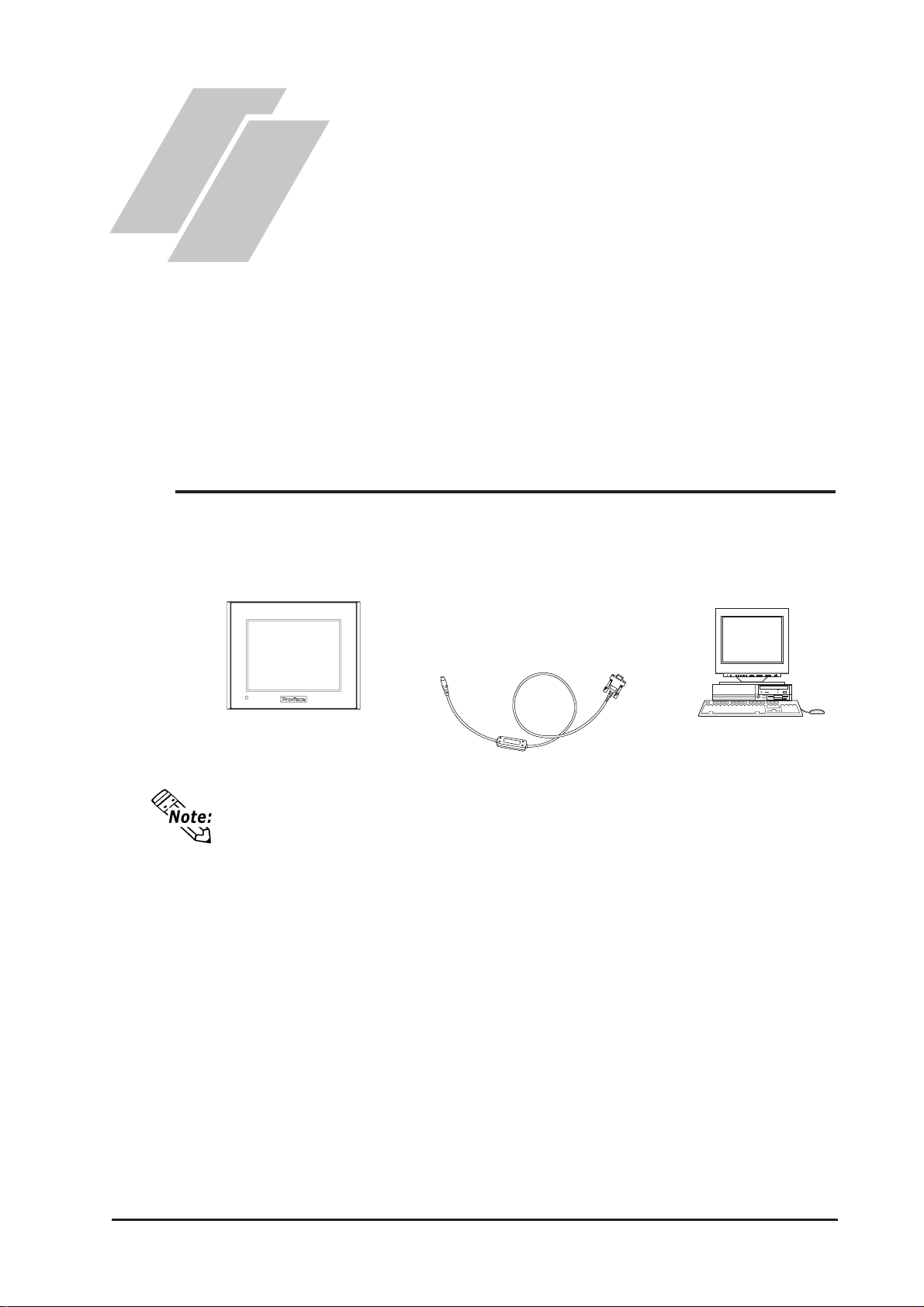
Chapter
4 Data Transfer
This chapter explains following three (3) methods of transferring data created with the
GP screen creation software to or from the GP.
• Transfer data via the data transfer cable to or from your GP.
• Transfer data via an Ethernet network to the GP.
• T ransfer data via the CF Card to or from your GP using the CF Memory Loader T ool.
4.1 Serial Data Transfer
The following explains how to connect Pro-face’s data transfer cable to your PC and to
the GP .
1. Serial Data Transfer
2. Ethernet Data Transfer
3. CF Memory Loader Tool
GP PC
Connected to
the GP’s Tool
Connector
• Pro-face’s transfer cable (GPW-CB02) is sold separately. The transfer cable
package does not include the PC’s interface converting adapter.
• When using the PC with the Dsub 25pin socket side interface, a connector
conversion adapter is required. Use the straight line type conversion adapter.
Recommended units:
Abel Co. AA833
Sanwa Supply Co. D09-9F25F
• When using a PC equipped with a half-pitch 14pin socket interface, a conversion adapter is required.
Recommended unit:
Arroz Co. ZR01-024
Connected to
the PC’s serial
port
GP-2300/2301 Series User Manual
4-1
Page 55
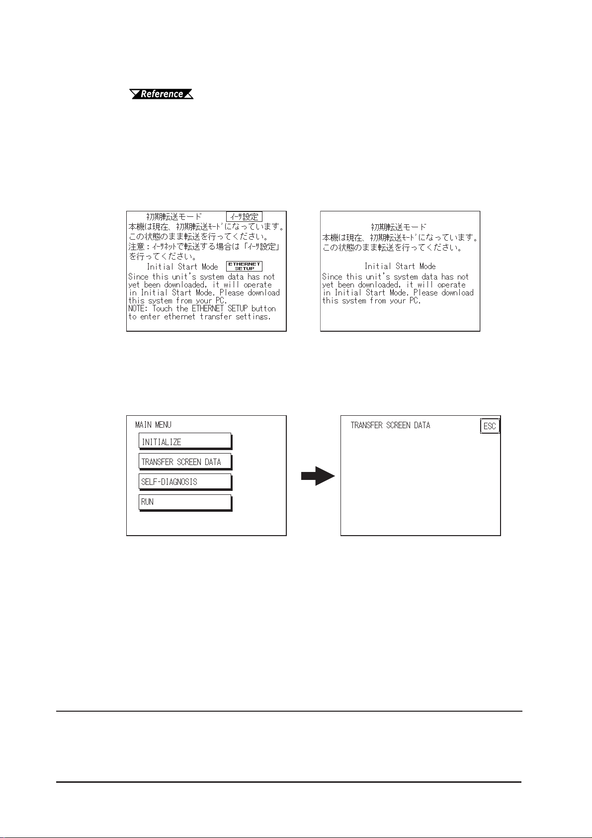
Chapter 4 - Data Transfer
Transfer screen data from your PC, via the GP screen creation software.
For details about the GP screen creation software, refer to GP-PRO/
PBIII for Windows Operation Manual (included in the GP scr een editor softwar e)
To Transfer Data to a Completely New GP
Connect the GP to your PC via the data transfer cable, and then turn the GP ON. The
“Initial Start Mode” screen will appear on the GP and you can transfer screen from your
PC. The screen will change to the “Transfer” screen automatically .
GP-2300 Series GP-2301 Series
After Completing Data Transfer using GP setup
Transfer screen data from the GP screen creation software, and select the “T ransfer” mode.
During data transfer, the “SETUP T ransfer” and “Now Transferring - Please W ait”
messages will appear. When these messages disappear , screen data transfer is completed.
If you wish to stop data transfer, simply cancel it from your PC’ s GP screen creation
software.
*1
4-2
If you try to set up the GP after data transfer, the OFFLINE mode’ s “Main Menu” will
appear. If you do NOT set up the GP, the screen designated in “INITIAL SETTINGS/
SCREEN SETUP/INITIAL SCREEN FILE NO. ” will appear and the screen will
change to operation (RUN) mode.
1* Here, the term “Set up” refers to the process of sending GP screen, system
program and protocol program information to the GP via the screen creation
software, so that the GP can be used as an operator interface.
GP-2300/2301 Series User Manual
Page 56

Chapter 4 - Data Transfer
Do NOT disconnect the GP’s power supply, turn OFF the PC, or disconnect the GP’s transfer cable during the data transfer . If you do, an error
may occur when the GP is started.
If the GP screen creation software’s “GP SYSTEM SETTINGS” data is transferred to the GP, the OFFLINE mode “INITIAL SETTINGS” data will be overwritten.
GP-2300/2301 Series User Manual
4-3
Page 57
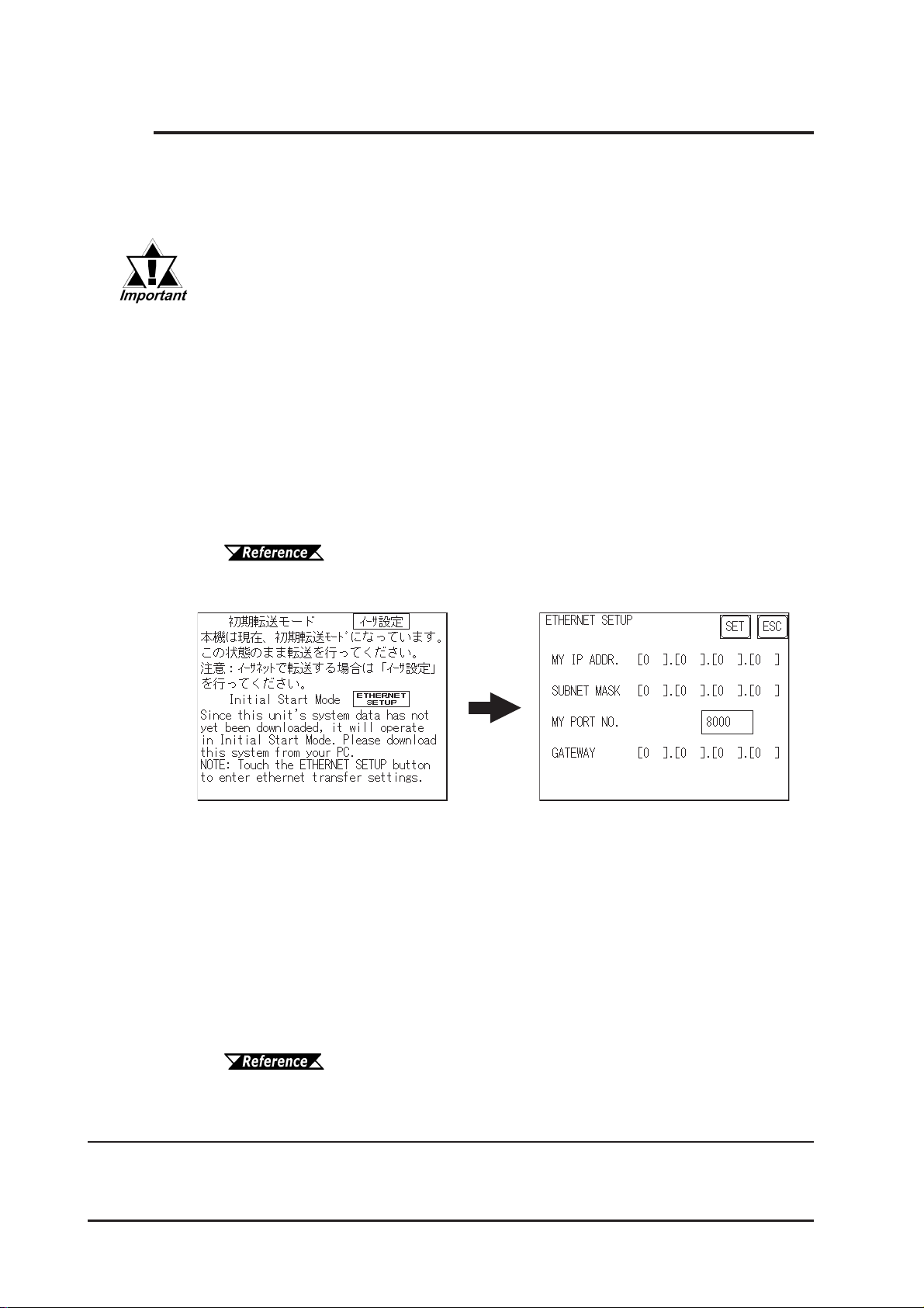
Chapter 4 - Data Transfer
4.2 Ethernet Data Transfer
The GP-2300 Series units are equipped with the Ethernet I/F which allows you to set
up the GP via an Ethernet network, as well as transfer GP screen data. (The GP-2301
Series units are not equipped with the Ethernet I/F .)
When using the Ethernet communication protocol, you must specify the
port number for the protocol as +10 or higher than the value specified in
this section. Otherwise, the setup or screen data transfer via Ethernet is
disabled.
After you connect an Ethernet cable to the GP’s Ethernet I/F, the GP will appear on the
Ethernet network.
Transferring Data to a Completely New GP
Setting Up the IP Address Manually and sending data to a GP
T ouch the “ETHERNET SETUP” button on the GP2300 Initial Start Mode screen.
6.5.4 Ethernet Setup
Use this method if the GP has been previously set up and data transferred to it.
Using a previously set up IP Address to send data
When the settings in the “Ethernet Setup” screen are not specified and data is sent,
the GP unit’ s factory-set IP Address settings are used.
If you choose to use the factory-set IP address, be sure to designate the PC’ s IP
Address from “10.255.255.1” to “10.255.255.254” and the subnet mask as
“255.0.0.0”.
*1
4-4
Use the GP-PRO/PBIII for Windows software to transfer the data.
“GP-PRO/PBIII for Windows Operation Manual” (included in
the GP screen editor software package)
* 1Be sure to use 2-Way2000 version 3.10 or higher. This version data can be seen
in the bottom left-hand corner of the [Initial Start Mode] screen.
GP-2300/2301 Series User Manual
Page 58
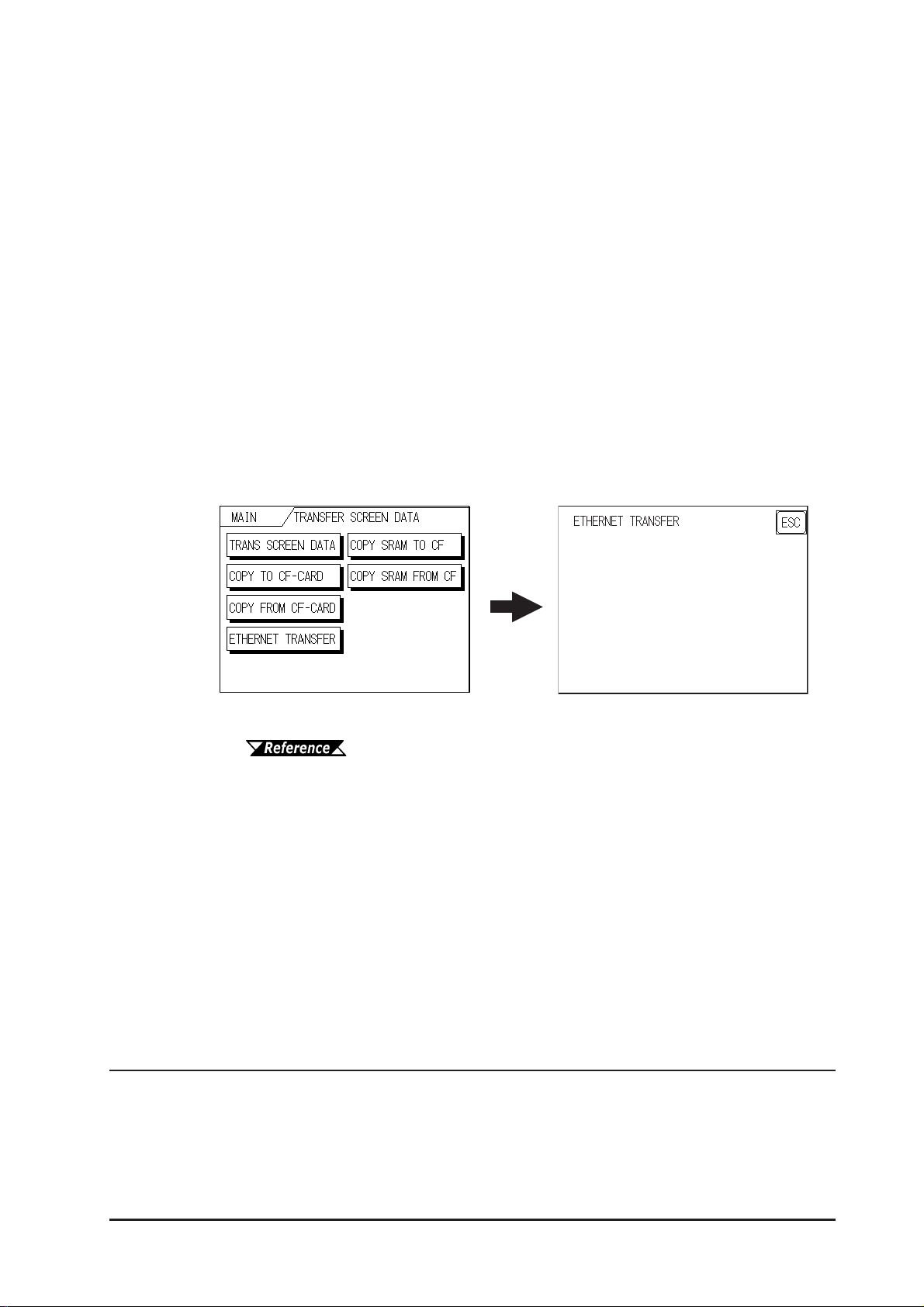
Chapter 4 - Data Transfer
When transferring data using the GP setup*1 is completed
How to manually set an IP address and transfer data
Set an IP address in the OFFLINE mode “INITIAL SETTING / OPERATING
ENVIRONMENT SETTING / EXTENSION SETTING / ETHERNET INFORMATION SETTING”. However, in case that an IP address is preset in the PC’s
screen editor software, the IP address is set in the GP. If the transferred IP address
is used, setting the GP’ s IP address again in the OFFLINE mode is not needed.
Set an IP address in the GP's through “INITIAL SETTING / OPERATING ENVIRONMENT SETTING / EXTENSION SETTING / ETHERNET INFORMATION SETTING” menu.
When you transfer screen data from your PC to the GP while the GP is in RUN
mode, the screen will change automatically to “Ethernet Mode”. If it does not, you
will need to manually change the GP screen to Ethernet Mode, via the following
screen.
Y ou can now transfer data from your PC’ s screen editor software.
GP-PRO/PBIII for Windows Operation Manual
How to transfer data using a previously-set IP address
*2
When transferring data without first setting up an IP address in the screen editor software, your GP unit's factory-set IP address is used.
When transferring data using your GP unit's factory-set IP address, be sure to set
“10.255.255.1” to “10.255.255.254” as your PC’s IP address, and “255.0.0.0” for
your PC's subnet mask.
The data transfer method is the same as when the IP address was manually set.
*1 Here, the term “Set up” refers to the process of sending GP screen, system
program and protocol program information to the GP via the screen editor
software, so that the GP can be used as an operator interface.
*2 Be sure to use 2-Way2000 version 3.10 or higher. This version data can be seen
in the bottom left-hand corner of the [Initial Start Mode] screen.
GP-2300/2301 Series User Manual
4-5
Page 59
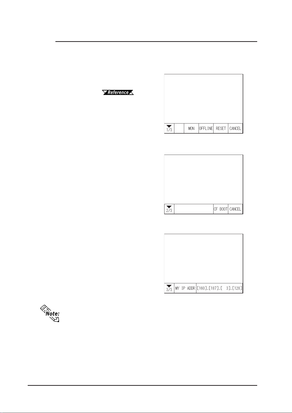
Chapter 4 - Data Transfer
4.2.1 Checking the IP Address
Use the following procedure to check the IP Address assigned to the GP and some
consideration/precautions.
1) Display the menu bar. For
instructions on how to display
the menu bar,
6.4.3 Set Up Touch Panel
2) Click on the left-side 1/3 cell of
the menu bar to display the next
menu.
3) Next, click on the 2/3 cell to
display the following menu.
4) The IP Address assigned to the
GP will appear in the menu
bar .
The IP Address will not be reflected unless GP was reset or power cord was reconnected. After changing “Ethernet Setup” settings, the GP must then be reset
or power cord must be reconnected.
4-6
GP-2300/2301 Series User Manual
Page 60
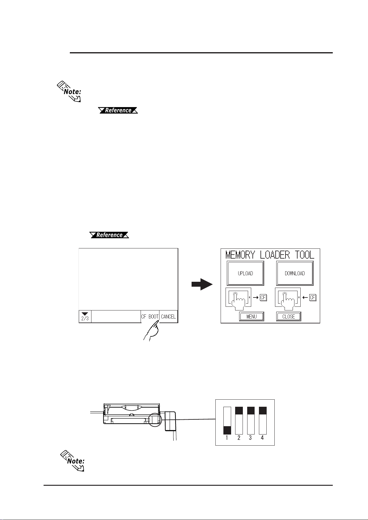
Chapter 4 - Data Transfer
4.3 CF Memory Loader Tool
The GP2300/2301 allow you to use the CF Memory Loader T ool in the CF Card to
set up the GP, transfer screen data, and upload GP internal data to its internal CF Card.
• You need to transfer the CF Memory Loader Tool to the CF Card prior to using
the CF Memory Loader Tool.
GP-PRO/PBIII for Windows Operation Manual
• When using GP-2300 Series units, the CF Memory Loader Tool and Backup
Data require more than 7MB of CF Card memory, and require more than 5MB
of CF Card memory when using GP-2301 Series units. When using Digital’s CF
Card “GP077-CF10 (8MB)”, if the combination of this data and your GP’s filing
data and image data collectively require more than 8MB, the memory space of
the CF Card will run out.
Starting the CF Memory Loader Tool
There are two methods for starting this program via the CF Card.
1. Menu Bar: Using the GP’s [CF BOOT] menu
Insert the CF Card with the CF Memory Loader T ool saved into the GP and touch the
menu screen’ s [CF BOOT] selection. The GP will be reset, and after it restarts, the CF
card’s “CF Memory Loader T ool” will start.
For how to display the Menu bar, refer to 6.4.3 Set Up Touch Panel
2. GP Dip Switches: Forced Start via GP Dip Switches
You can also use the Dip Switches on the rear of the GP, next to the CF Card Slot. If
you turn ON Dip Switch No.1 (lower it) and then connect the GP unit’ s power cord,
the “CF Memory Loader T ool” will automatically start.
CF Card Slot
When you finish using the CF Memory Loader Tool, be sure to turn this dip
switch OFF .
GP-2300/2301 Series User Manual
Dip Switches
OFF
ON
4-7
Page 61
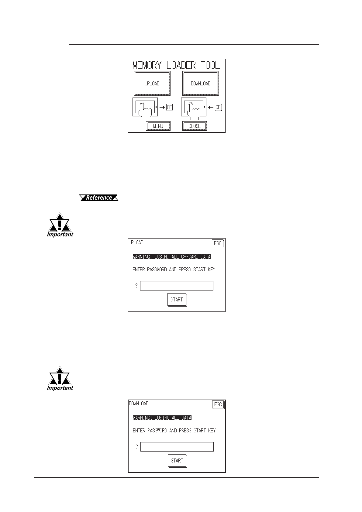
Chapter 4 - Data Transfer
4.3.1 Data Upload and Download
When the Memory Loader T ool program starts, the following screen will appear .
UPLOAD (From GP to CF Card)
This feature is for saving all GP internal data (i.e. system program, communication protocol,
expansion program, screen data and Backup SRAM data) in the CF Card as backup data.
T o start data upload, enter the password you designated in the GP screen creation
software’s “T ransfer” screen, and then touch the “ST ART” key . If you have not designated a
password however, simply touch the “ST AR T” key.
For more information about Passwords, Chapter 6.3.1, "System
Setup" and Chapter 5.3, "Initialization”
When UPLOAD is performed, the CF Card’s current Backup Data will be
completely overwritten.
DOWNLOAD (From CF Card to GP)
This feature is used for writing CF Card backup data to the GP’s Internal SRAM Memory .
T o start data download, enter the password you designated in the GP screen creation
software’s “T ransfer” screen, and touch the “ST ART” key . If you have not designated a
password, simply touch the “ST ART” key .
When DOWNLOAD is performed, the GP’s Internal Memory data (i.e. system program, communication protocol, expansion program, screen data
and Backup SRAM data) will be completely overwritten.
4-8
GP-2300/2301 Series User Manual
Page 62
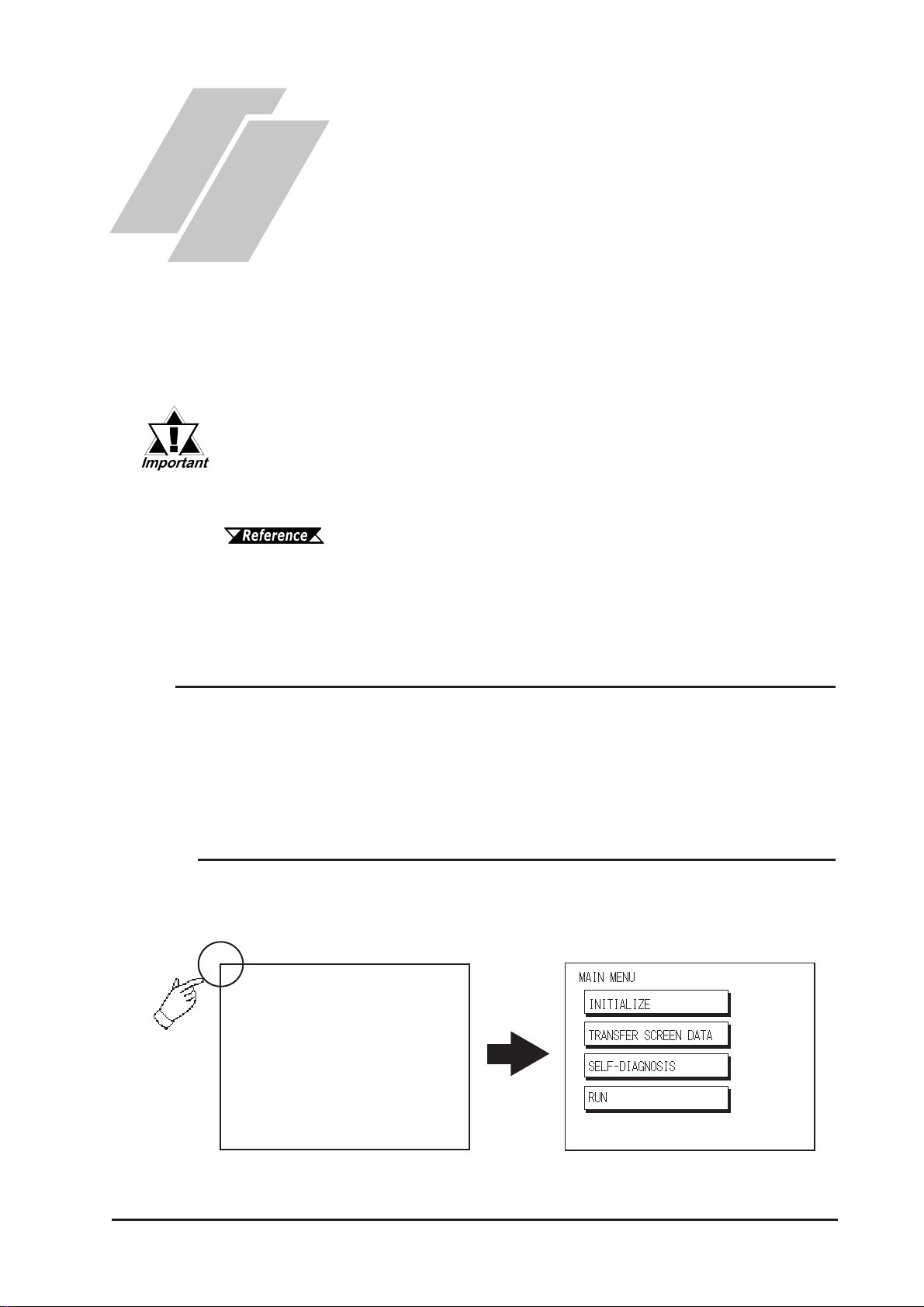
Chapter
5 OFFLINE Mode
OFFLINE Mode provides access to the Initialize, Self-Diagnosis, and other features
built into the GP . Before you can use any of these features, however , you will need to
change the GP to OFFLINE mode.
OFFLINE mode is unavailable in a completely new GP until the necessary GP system data has been transferred from your PC’s screen editor
software. To do this, be sure the GP's power cord is plugged.
”Data Transfer”, or the GP-PRO/PBIII for W indows Operation Manual (included in
the screen creation software)
1. Entering OFFLINE Mode
2. OFFLINE Mode Main Menu
3. Initialization
4. Self-Diagnosis
For information about transferring data to the GP, refer to Chapter 4-
5.1 Entering OFFLINE Mode
T o INITIALIZE your GP or perform SELF-DIAGNOSIS, you must first switch the
GP to OFFLINE mode. There are two ways to enter OFFLINE mode. First, is
immediately after plugging in the GP's power cord, and second, by using the Forced
Reset feature.
5.1.1 After Plugging in the Power Cord
Touch the upper left-hand corner of the GP screen within 10 seconds of plugging
in the GP's power cord and the GP will change to OFFLINE mode.
GP-2300/2301 Series User Manual
5-1
Page 63
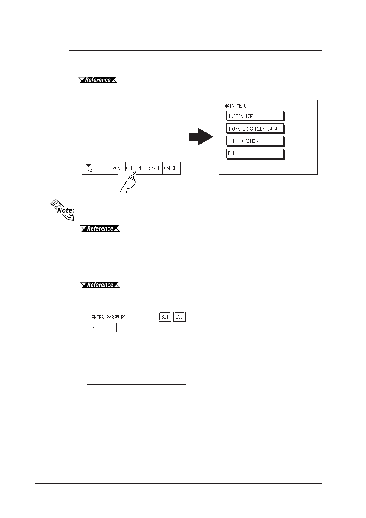
Chapter 5 - OFFLINE Mode
5.1.2 From the Menu Bar
From the GP unit’ s Menu Bar, touch the OFFLINE square and the OFFLINE mode
Main Menu will appear.
For instructions on how to call up the Menu Bar, refer to 6.4.3 “Set Up
Touch Panel”
If your GP unit has the Device Monitor feature, the “Monitor” square will also appear.
GP-PRO/PBIII for Windows Device/PLC Connection Manual (in-
cluded with the screen creation software), Appendix 3 - Device Monitor
If a Password has been entered in the INITIALIZE/ SET UP SYSTEM area, before
entering the OFFLINE mode, the following screen appears.
Here, enter the password, then touch Set to enter OFFLINE mode.
For more information about Passwor ds, r efer to Chapter 6.3.1, "Sys-
tem Setup" and Chapter 5.3, "Initialization”
5-2
GP-2300/2301 Series User Manual
Page 64
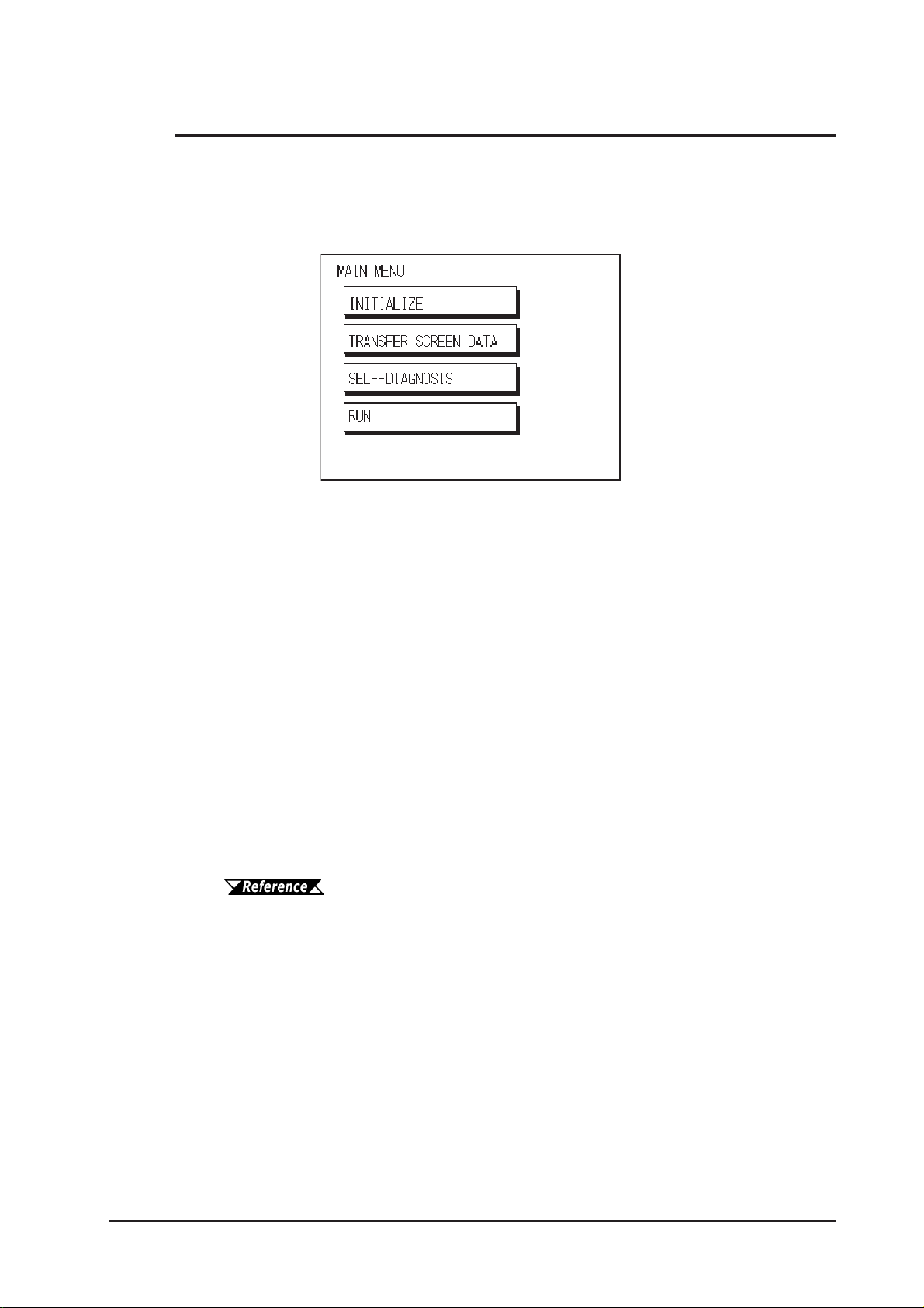
Chapter 5 - OFFLINE Mode
5.2 OFFLINE Mode Main Menu
Each menu item shown below has different settings that must be set to match the
corresponding PLC in order for the GP to communicate properly.
Entering OFFLINE mode calls up the following screen.
Select the desired menu item by touching the corresponding screen item bar .
Each Main Menu item is used as follows.
QQ
Q INITIALIZE
QQ
The setup items contained in this menu are used to control the GP unit.
QQ
Q SCREEN DAT A TRANSFER
QQ
Select to transfer screen data to and from the screen editing software.
QQ
Q SELF-DIAGNOSIS
QQ
Checks to see if there are any problems with the GP System or Interface (I/F).
QQ
Q RUN
QQ
Starts GP operation.
For more information about INITIALIZE, refer to Chapter 6.
For more information about TRANSFER SCREEN DATA, refer to Chapter 4 or GP-
PRO/PBIII for Windows Operation Manual (included with the scr een cr eation softwar e).
For more information about SELF-DIAGNOSIS and RUN, refer to Chapter 7.
GP-2300/2301 Series User Manual
5-3
Page 65
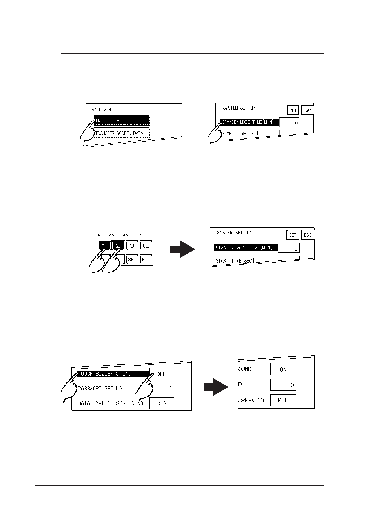
Chapter 5 - OFFLINE Mode
5.3 Initialization
QQ
Q Selecting A Menu
QQ
T ouch the menu item, or input field to select it.
QQ
Q Entering Numbers
QQ
After selecting an input field by touching it, use the numeric touch keys located at the
bottom of the screen to enter numeric values. After inputting each value, touch the
[SET] key to define the value.
QQ
Q Selecting Setup Conditions
QQ
After selecting a menu item and entering that area, touch the option you would like to
setup. The selected item becomes highlighted. In this example, the TOUCH BUZZER
SOUND has been set Off.
5-4
GP-2300/2301 Series User Manual
Page 66
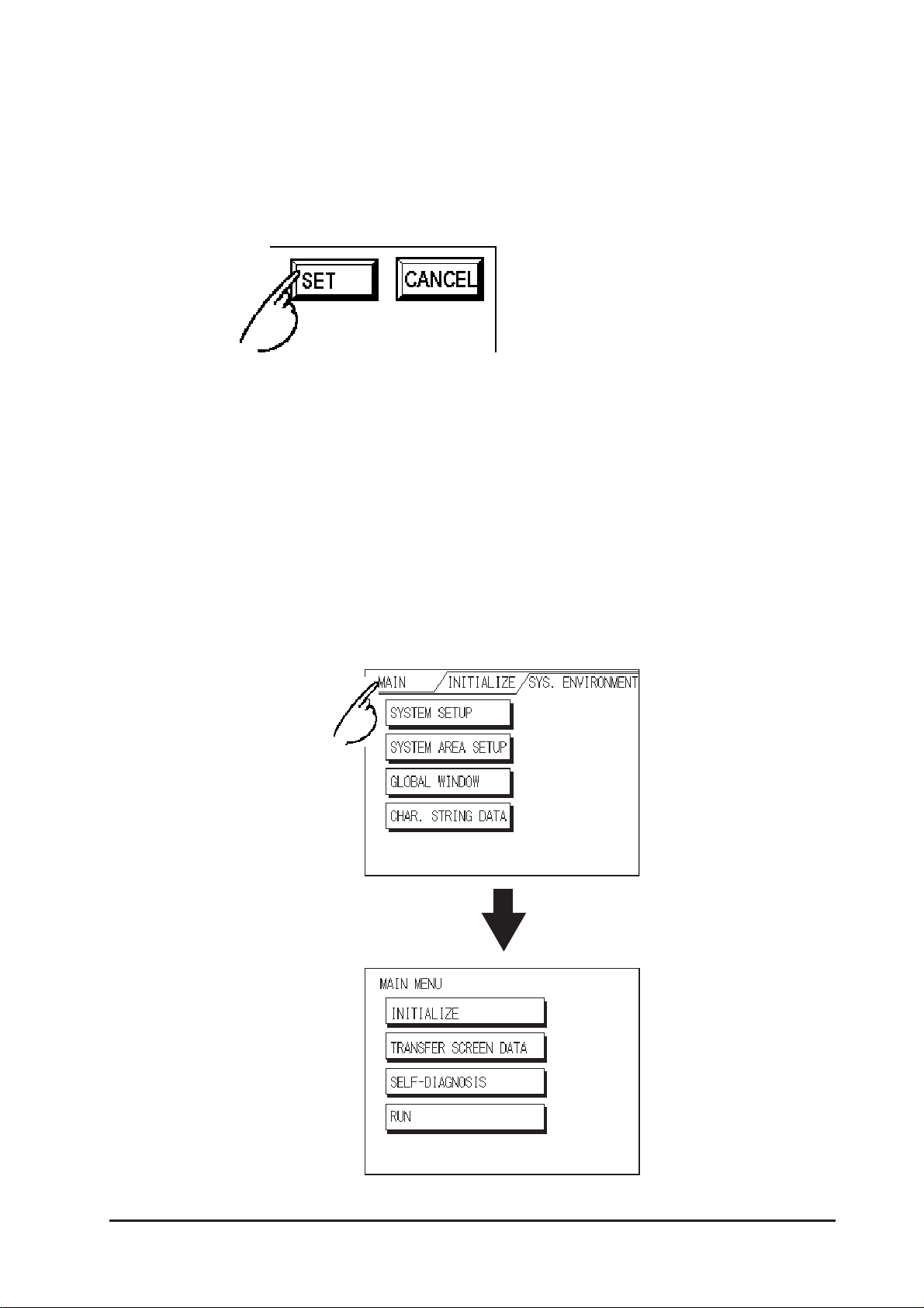
Chapter 5 - OFFLINE Mode
QQ
Q After All Setting Data is Entered
QQ
T ouch the top-right [SET] button.
If you wish to exit the screen without saving the changes, touch the CANCEL button.
• Press the [SET] key to write the Setup
conditions onto the Internal FEPROM,
which may take some time, causing a delay
in returning to the previous screen. Therefore, do not touch the screen until the
previous menu display returns.
• Press the [SET] key to write the Setup
conditions onto the Internal FEPROM,
and Press the [CANCEL] key to not write
the Setup conditions onto the Internal
FEPROM and return to the previous menu.
QQ
Q Return To Previous Screen
QQ
T ouch the title of the screen you would like to return to.
E.g. T o return to the MAIN MENU from the SYS.ENVIRONMENT screen, simply
touch the MAIN MENU title.
GP-2300/2301 Series User Manual
5-5
Page 67
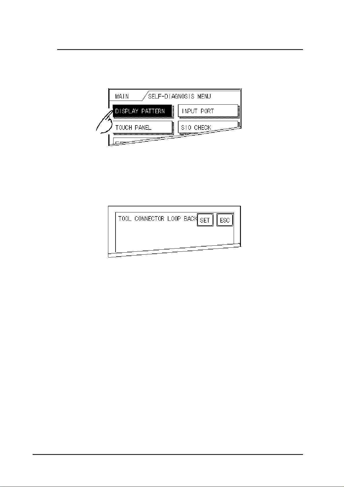
Chapter 5 - OFFLINE Mode
5.4 Self-Diagnosis
Q Selecting a Sub-Display
T ouch the desired the menu item and that sub-display will appear.
Q [SET], [ESC] Keys
After selecting the Self Diagnosis item, the [SET], and [ESC] keys may appear at
different times at the top of the screen.
X [SET] Key
When this key is pressed, your selected Self-Diagnosis test begins.
X [ESC] Key
When this key is pressed, the selected Self-Diagnosis test is cancelled, and you
are returned to the SELF-DIAGNOSIS menu.
5-6
GP-2300/2301 Series User Manual
Page 68
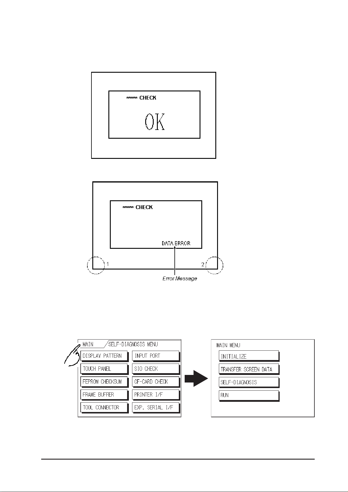
Chapter 5 - OFFLINE Mode
Q After Check—To Return To SELF-DIAGNOSIS MENU
When OK displays,
Pressing once anywhere on the
display screen returns you to the
SELF-DIAGNOSIS MENU.
When an Error Message displays
When an error message appears on
the display screen, touch the
bottom two corners of the panel (1,
2) to return to the
SELF-DIAGNOSIS MENU.
Q Return To Main Menu
T ouch the MAIN Key in the top right corner of the SELF-DIAGNOSIS menu to return
to the MAIN MENU.
GP-2300/2301 Series User Manual
5-7
Page 69

Memo
5-8
GP-2300/2301 Series User Manual
Page 70

1. Initialization Screen
2. Initialization Items
3. System Environment Setup
4. Set Up I/O
Chapter
5. PLC Setup
6 Initializing the GP
6.1 Initialization Screen
Occasionally , you may want to change your GP's general operation settings. The settings
used for this are found in the INITIALIZE option in the GP OFFLINE mode's MAIN
MENU.
This chapter explains each of the OFFLINE mode's INITIALIZE items. However,
there are 2 types of INITIALIZE settings, those for the 1:1 connection and those for
the n:1 (multi-link) connection*1.
The n:1 mark appears on original menu items related to n:1 multi-link connection items.
If there is no mark, the menu item is common to both 1:1 and n:1 connections.
6. Initialize Internal Memory
7. Set Up Time
8. Set Up Screen
9. Font Setting
1:1 A single (1) GP is connected with a single (1) PLC.
n:1 Multiple GPs are connected with a single PLC. The GPs successively pass a PLC
Access T oken (exclusive PLC interaction key) among themselves to designate
which unit can communicate with the PLC.
If you transfer the GP's system file data to the GP via your screen design soft-
*2
ware
setup and transferred, the setting of INITIALIZE items become unnecessary.
III for Windows Operation Manual" (included with screen creation software)
, the GP operates using that data. If the GP System file has been correctly
For more information about GP System files, refer to "GP-PRO/PB
*1 PLC's that support the n:1 (multi-link) connection are limited.
" GP-PRO/PB III for Windows Device/PLC Connection Manual" (in-
cluded with the screen cr eation softwar e)
*2 Refer to GP screen creation software's "SYSTEM SETTINGS" area.
GP-2300/2301 Series User Manual
6-1
Page 71
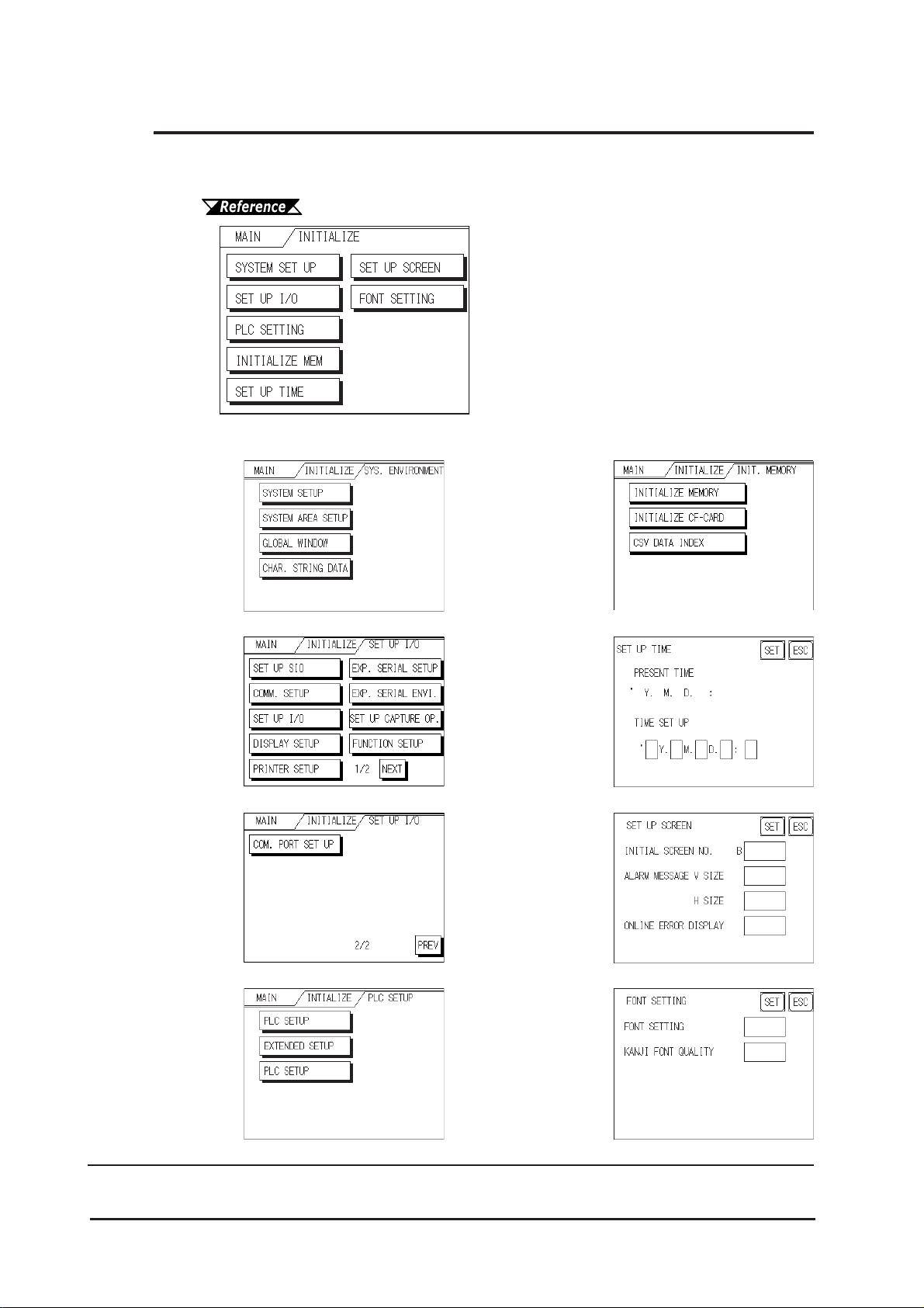
Chapter 6 - Initializing the GP
6.2 Initialization Items
This chapter explains the contents of the Initialize setup items listed below . For information about screen operations and numeric input.
Chapter 5, "OFFLINE Mode"
The INITIALIZE menu includes the following items.
SYSTEM
ENVIRONMENT
SETUP
SYSTEM SETUP
SYSTEM AREA SETUP
GLOBAL WINDOW
CHAR. STRING DATA
SET UP I/O
SET UP SIO
COMM. SETUP
SET UP I/O
DISPLAY SETUP
PRINTER SETUP
(GP-2300 Series unit only)
EXP. SERIAL SETUP
EXP. SERIAL ENVI.
(GP-2300 Series unit only)
SET UP CAPTURE OP.
FUNCTION SETUP
COM. PORT SET UP
INITIALIZE MEMORY
INITIALIZE MEMORY
INITIALIZE CF-CARD
CSV DATA INDEX
SET UP TIME
SET UP SCREEN
PLC SETUP
PLC SETUP
EXTENDED SETUP
PLC SETUP
*1
6-2
FONT SETTING
* 1Note that, depending on the Device/PLC type selected, the screens that appear in
your GP’s screen editor software will vary.
GP-2300/2301 Series User Manual
Page 72
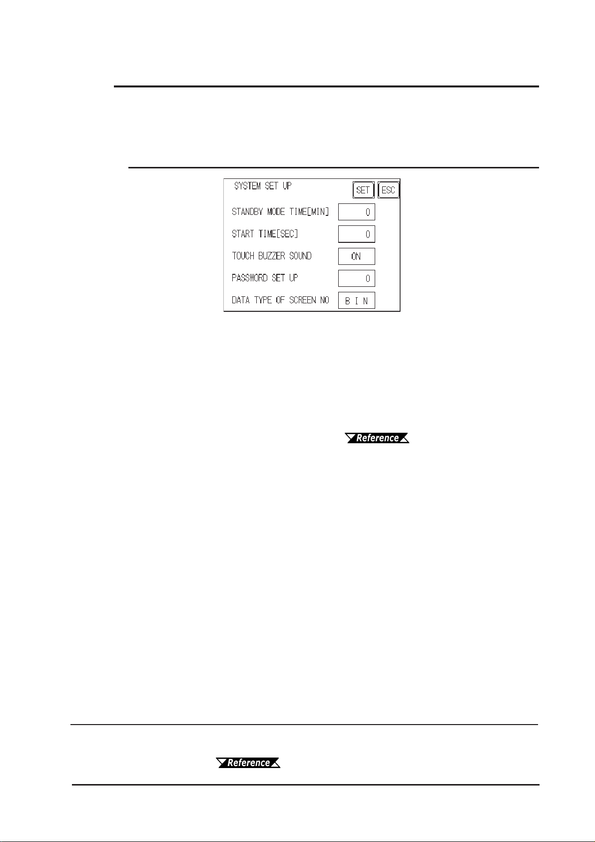
Chapter 6 - Initializing the GP
6.3 System Environment Setup
These settings allow you to adjust the GP's operation environment. SYSTEM ENVIRONMENT SETUP includes the SYSTEM SETUP , SYSTEM DAT A AREA,
GLOBAL WINDOW SETUP , and CHARACTER STRING DAT A SETUP screens.
6.3.1 System Setup
STAND-BY MODE TIME [MIN]
To extend the life of the GP's backlight, the GP is equipped with a screen saver function
that automatically turns the unit's backlight(s) OFF when no operations have occurred
for a designated period of time. A "0" entered in this field causes a normal display , i.e.
the screen is cleared after the GP's standard default time elapses.
When SYSTEM DATA AREA's SCREEN DISPLA Y OFF*1 data is 0000h, and the
following operations are not performed on the screen for the User's designated period of
time, the GP's current display is turned OFF . ( "GP-PRO/PBIII for
Windows Device/PLC Connection Manual" - included with the screen creation
software)
• Change Screen • T ouch Screen
• Alarm Messages (scrolling display)
• Error Message Display (Except for 2W ay Error)
• Menu Bar (for forced reset) display • Japanese (FEP) System window
START TIME [SEC]
This setup determines the start-up time of the GP . Use this setup to adjust the power up
sequence so that the GP starts up after the PLC.
TOUCH BUZZER SOUND
Setup whether or not the GP beeps when pressed.
PASSWORD SETUP
The password setting is used when changing to the Initialize Memory or Initialize
(OFFLINE mode) Screens. The password (from 0 to 9999) ensures protection of the
GP settings, since the use of OFFLINE mode is controlled. If you do not wish to use
this feature, enter the default value, 0.
*1 When using the Direct Access or the Memory Link formats, the object address
becomes +9 or +12, respectively. (Only when all items are set within the System
Data Area.)
Manual" (included with the screen creation software)
GP-2300/2301 Series User Manual
"GP-PRO/PBIII for Windows Device/PLC Connection
6-3
Page 73
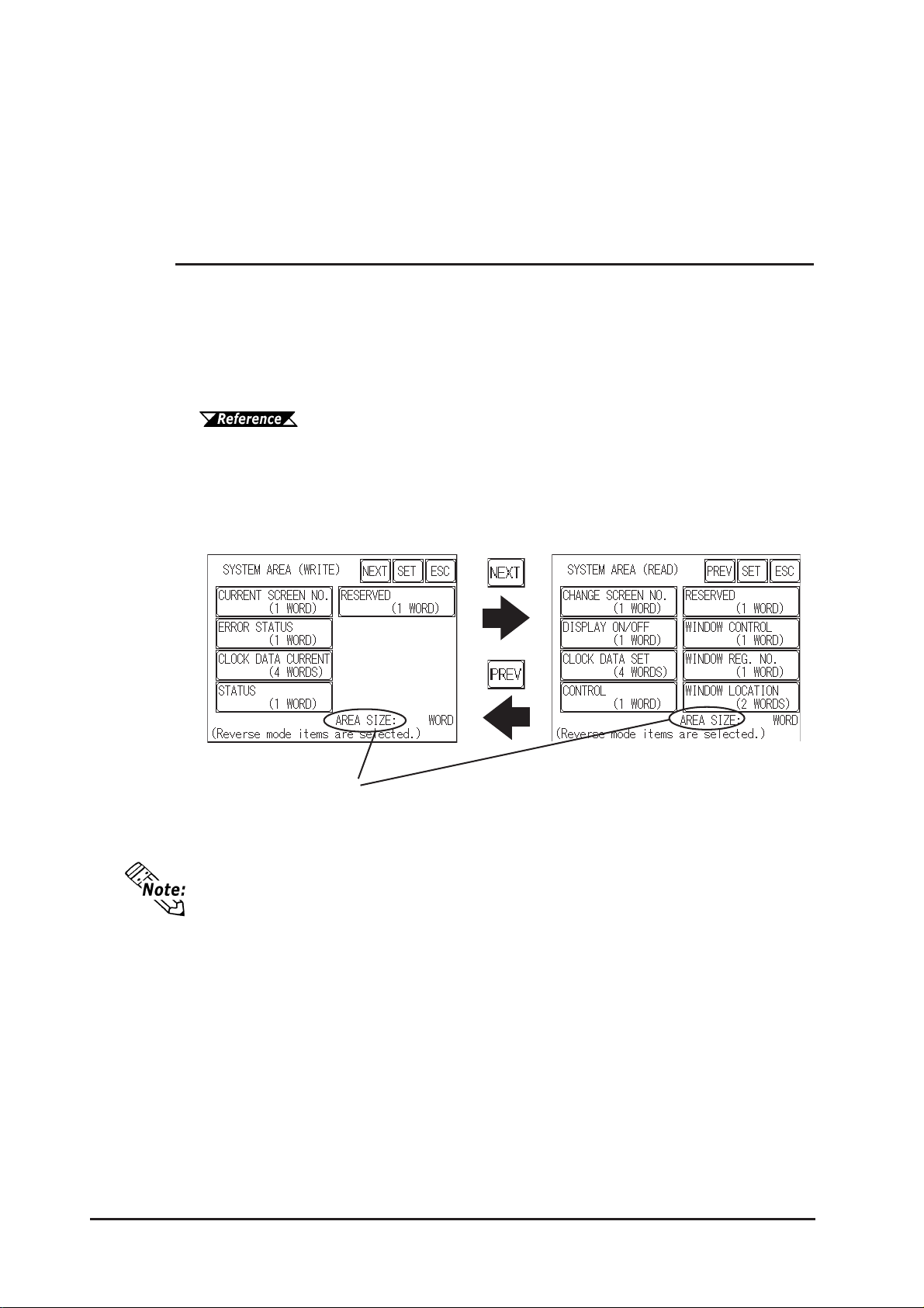
Chapter 6 - Initializing the GP
DAT A TYPE OF SCREEN NO.
This setup controls whether BIN or BCD format numbers are used when making screen
changes. Screen numbers 1 to 8999 are available for binary format; screen numbers 1
to 1999 are available for BCD format.
6.3.2 System Area Setup
SYSTEM AREA SETUP is necessary for the PLC to control its GP-related data, and
prepares the PLC internal Data Memory (DM) and Data Register (D)*1. Use this setup
to prepare the desired SYSTEM DA TA AREA items. SYSTEM DA T A AREA is
located in the LS area of the GP's internal area.
When using the Memory Link format, this setting is unnecessary.
GP-PRO/PB III for Windows Device/PLC Connection Manual
(included with the screen creation software)
Press the item, and when the item is highlighted, it has been selected.
When you press the Confirm key , the SYSTEM AREA CONTENTS screen appears to
confirm the selected items.
System Area Size
This field displays the total number of words used for the items selected from the
SYSTEM AREA SETUP (Write and Read ).
• The setup shown is enabled only when using the Direct Access format.
• The selected System Area items, as displayed on the screen, become the System Data Area.
6-4
GP-2300/2301 Series User Manual
Page 74
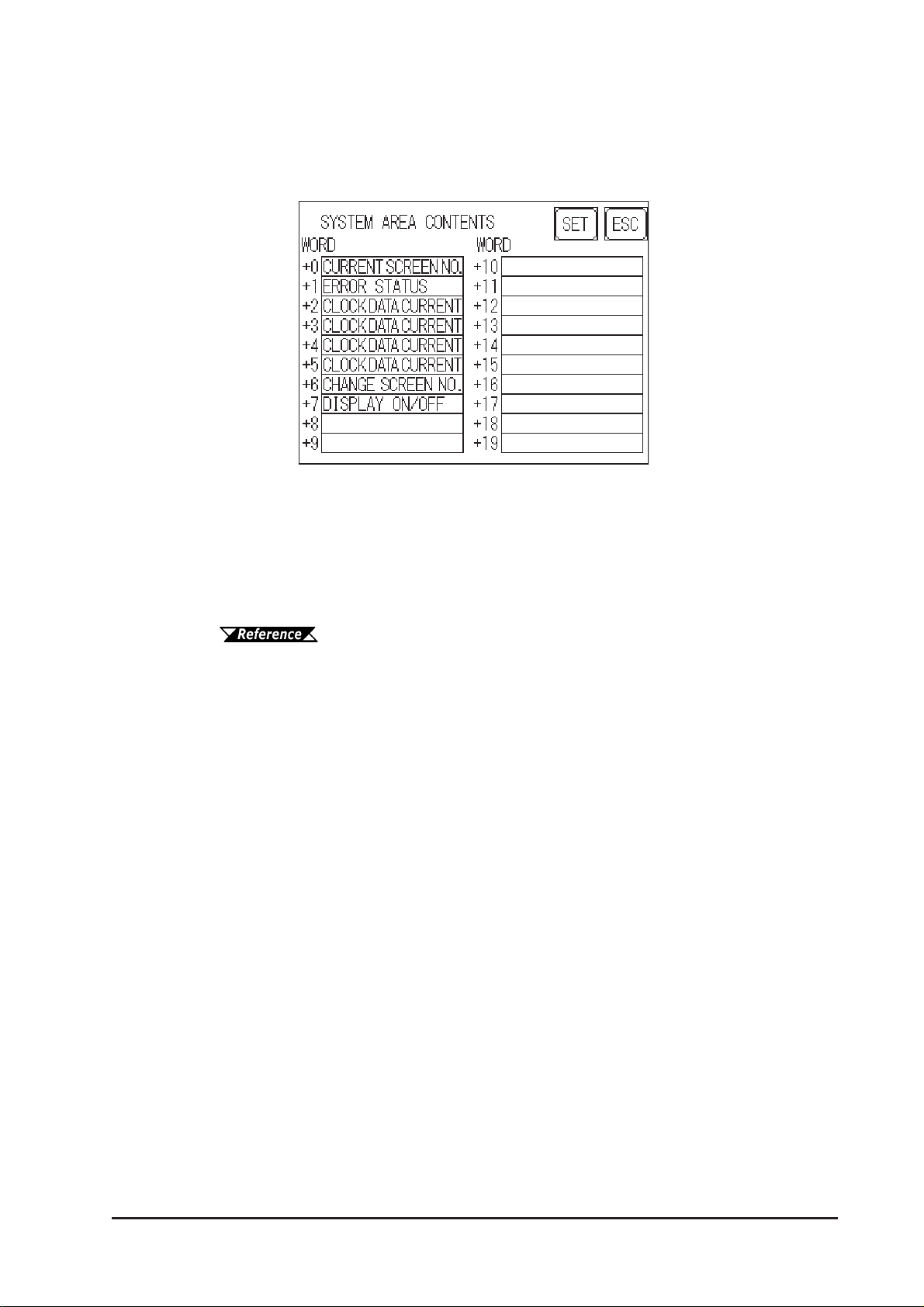
Chapter 6 - Initializing the GP
When these five items, "Current Screen Number", "Error Status", "Clock Data (Current)",
"Change Screen Number", and "Display ON/Off", have been selected, word addresses
are assigned to each item, in order, as shown here.
The System DataArea selection process follows this formula [System Data Start Address + n]. For example, if the System Area Start Address was D00200, and the
Change Screen Number option had been selected—if you refer to the System Area
Contents screen displayed above—because Change Screen No's address is +6, its
word address would be D00200+6=D00206.
For information about how to use the System Start Address and Start
Address, 6.5.1 Set Up Operation Surroundings
GP-2300/2301 Series User Manual
6-5
Page 75
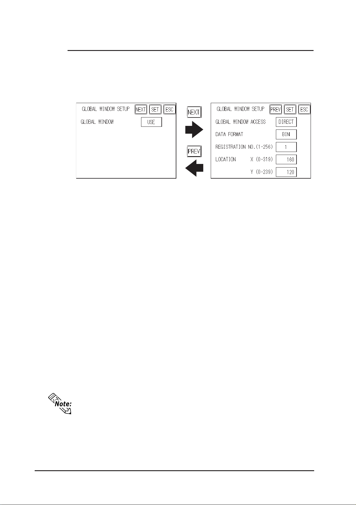
Chapter 6 - Initializing the GP
6.3.3 Global Window Setup
The GP unit can display three screens at any one time, one Global Window and two
Local Windows. The Global W indow is common to all the display screens. The Local
Window displays exclusively on the corresponding base screen. The GLOBAL WINDOW SETUP is described here.
GLOBAL WINDOW
There are two options here: Use and Do Not Use. If you select Do Not Use, ignore
the items described below . Selecting Use enables these options.
GLOBAL WINDOW ACCESS
Use this feature to designate whether a value used is DIRECT or INDIRECT , i.e. the
REGISTRATION NO . and the LOCATION values.
When set as Direct, the REGISTRATION NO. and LOCATION selections are fixed to the
values entered here.
When set to Indirect, the WINDOW REG. NO.'s word address, as prepared in the
System Area, is a variable. This means it can have the REGISTRATION NO. written to it
and, as a result, multiple window screens can be used as Global windows. Y ou can use
this method to adjust the Global window position by writing the X,Y coordinates to the
SYSTEM AREA's LOCATION word addresses.
DAT A FORMAT
Setup whether the REGISTRATION NO. and the LOCA TION values are BIN or
BCD values. This field is related only to indirect values.
REGISTRATION NO. (1-256)
6-6
Enter the Window Screen Number used by the Global W indow . This field is enabled
only when GLOBAL WINDOW ACCESS is set to direct.
The GP unit's screen editor software allows you to set a window number from 1
to 2000. If you wish to use a number that is 257 or higher, be sure to use the GP
unit's screen editor software to enter this value.
LOCATION
Enter the value used for the (Global WINDOW) LOCA TION. This field is enabled
only when GLOBAL WINDOW ACCESS is set to direct.
GP-2300/2301 Series User Manual
Page 76
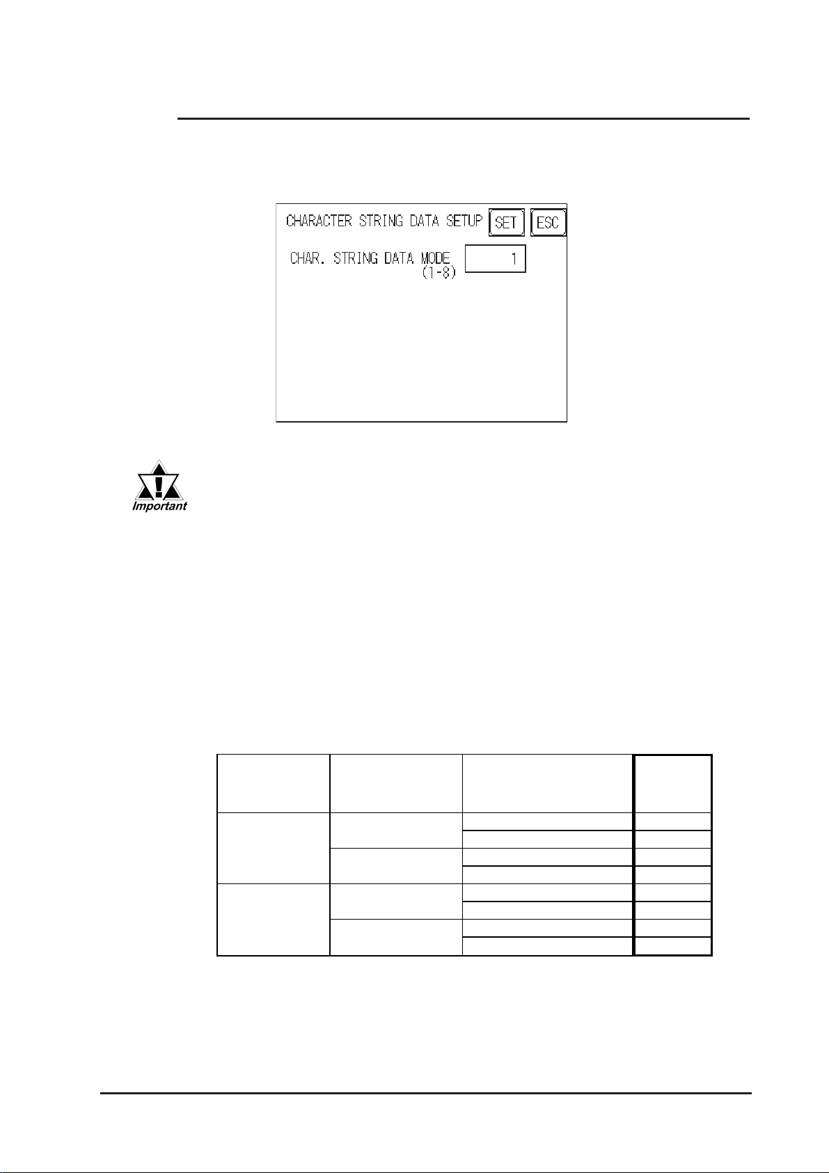
Chapter 6 - Initializing the GP
6.3.4 Character String Data Setup
Character String Data ordering varies from manufacturer to manufacturer . Setup the
Character String Data order here to match the corresponding PLC.
Setup the CHARACTER STRING DATA MODE to match the PLC type.
Device type and Tag settings are unavailable.
CHARACTER STRING DAT A MODE (1-8)
Find the data storage order for your PLC in the table, down below , and setup the
CHARACTER STRING DA T A MODE.
(I) Data Device Storage Order
(II) Internal W ord Byte LH/HL Storage Order
(III) Internal Double-word Word LH/HL Storage Order
Character String Data Mode List
(I) Data Device
Storage
Order
St orage from
Initial data
St orage from
End data
(II) Internal W ord,
Byte LH/HL
Storage Order
LH order
HL order
LH order
HL order
(III) Doubl e-word
Internal Word LH/HL
Storage Order
LH order
HL order
LH order
HL order
LH order
HL order
LH order
HL order
Character
String
Data Mode
4
2
5
1
6
7
8
3
GP-2300/2301 Series User Manual
6-7
Page 77
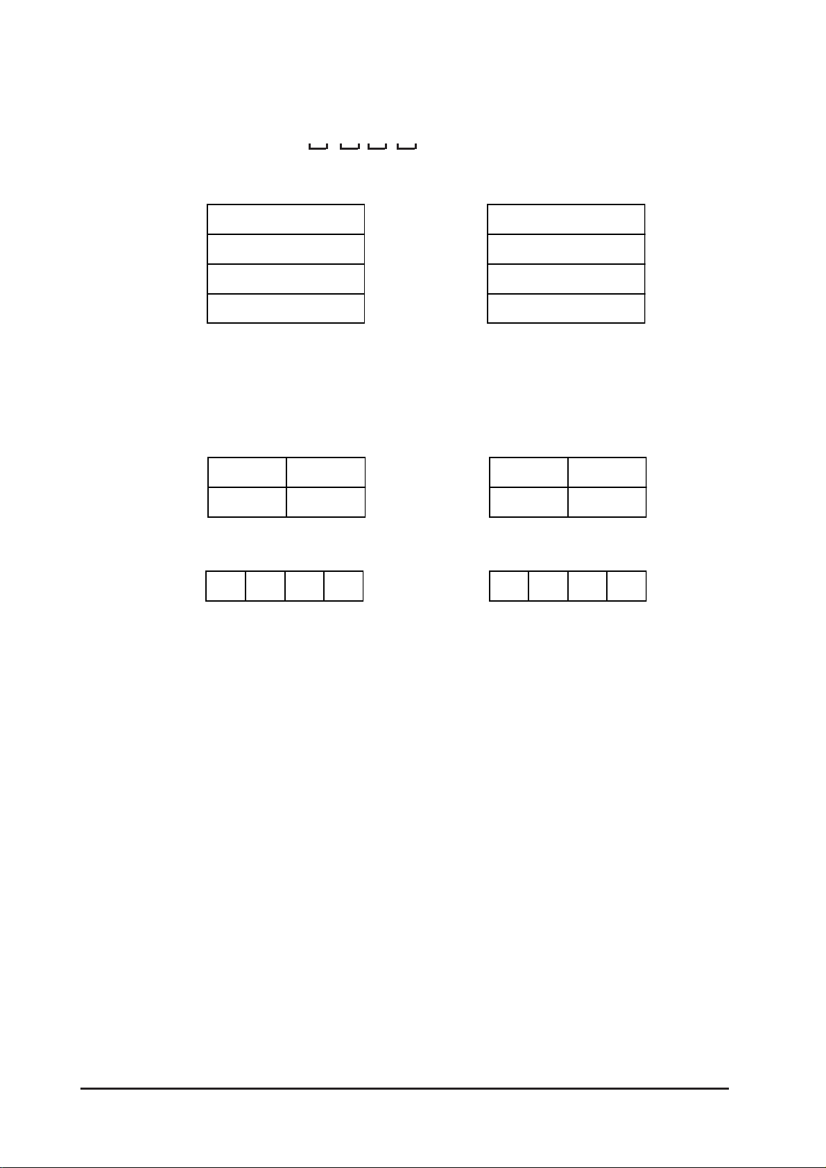
Chapter 6 - Initializing the GP
I) Data Device Storage Order
E.g. Characters "A B C D E F G H"
• Storage from Start Data • Storage from End Data
II)Word Byte LH/HL Order
E.g. Characters "A B C D"
• 16 bit Device LH Order • 16 bit Device HL Order
• 32 bit Device LH Order • 32 bit Device HL Order
D100
D101
D102
D103
D100
D101
D100 D100
D100
D101
D102
D103
D100
D101
6-8
GP-2300/2301 Series User Manual
Page 78
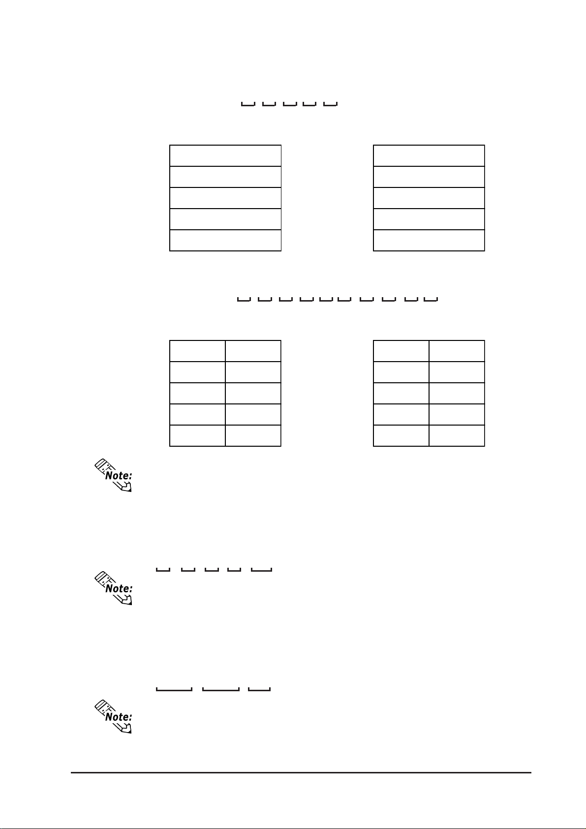
Chapter 6 - Initializing the GP
III) Double-word Word LH/HL Order
E.g. Characters "A B C D E F G H I J"
• 16 bit Device LH Order • 16 bit Device HL Order
D100
D101
D102
D103
D104
E.g. Characters "A B C D E F G H I J K L M N O P Q R S T"
• 32 bit Device LH Order • 32 bit Device HL Order
D100
D101
D102
D103
D104
D100
D101
D102
D103
D104
D100
D101
D102
D103
D104
Relationship between K-tag Write Character Value and PLC Device
• 16 bit Devices
GP stores the character string from the start, as groups of 2, into1 PLC Device.
When there are nine characters, they are arranged as shown below .
1 2 3 4 5 6 7 8 9 Null
When the characters do not divide into 2 evenly, NULL is added at the end.
• 32 bit Devices
GP stores the character string from the start, as groups of 4, into1 PLC Device.
When there are nine characters, they are arranged as shown below .
1 2 3 4 5 6 7 8 9 Null
When the characters do not divide into 4 evenly, NULL is added at the end.
GP-2300/2301 Series User Manual
6-9
Page 79
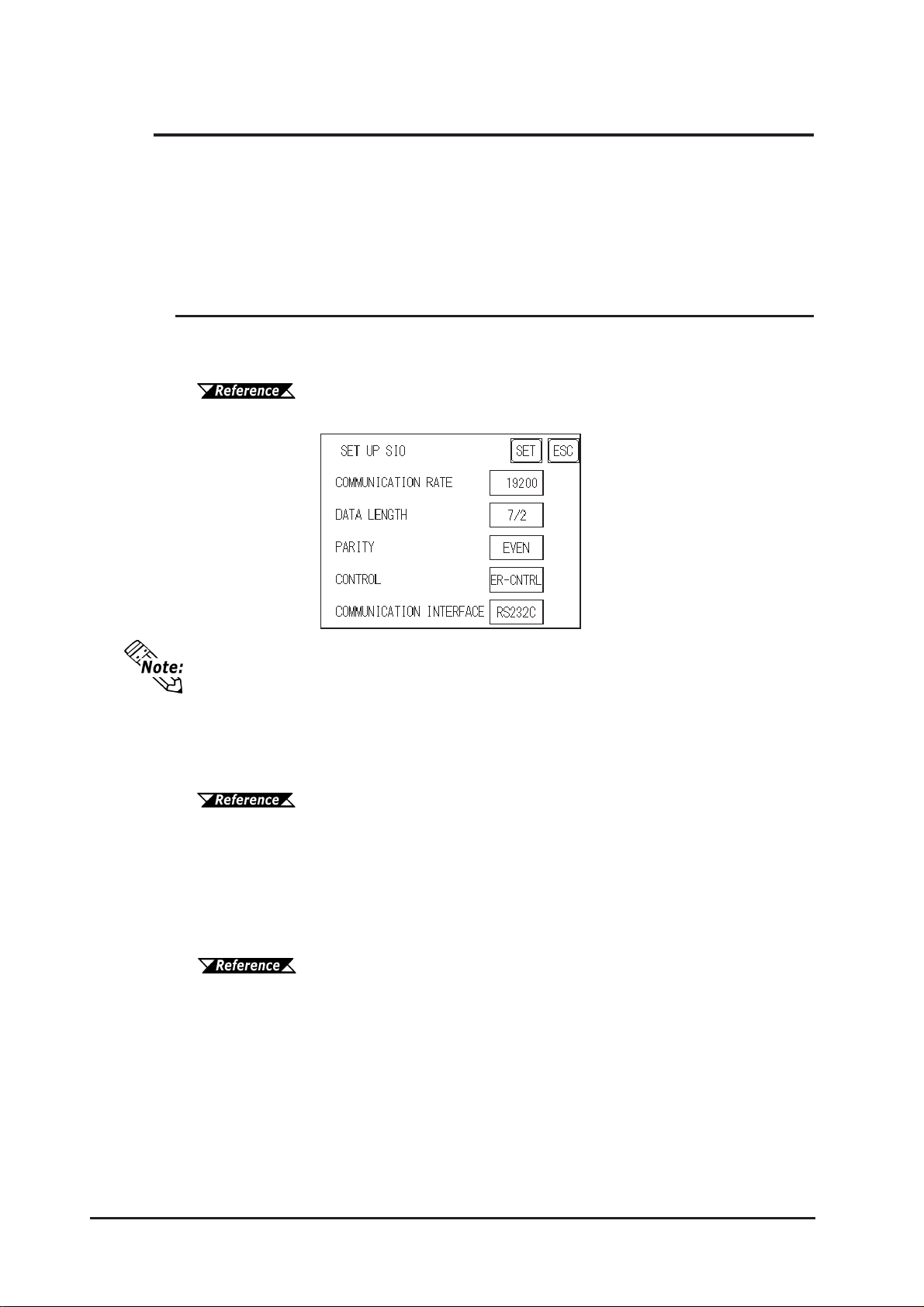
Chapter 6 - Initializing the GP
6.4 Set Up I/O
This section describes the communication setup with the Host (PLC) and the setup for
any peripheral equipment. The SET UP I/O menu includes the SET UP SIO, COMMUNICATION SETUP , SETUP I/O, DISPLAY SETUP, PRINTER SETUP , EXP ANSION SERIAL SETUP, EXP ANSION SERIAL ENVIRONMENT SETUP,
SET UP CAPTURE OPERATION, FUNCTION SETUP and COMMUNICA TION
PORT SET UP menus.
6.4.1 Set Up SIO
This menu runs the settings related to PLC communication. Be sure to match the
settings listed below with the SIO setup on the PLC host, if not, an error may occur.
GP-PRO/PBIII for Windows Device/PLC Connection Manual
(included with screen cr eation software)
If you have selected "YES" for the [SERIAL I/F CHANGE] on the [COMMUNICATION PORT SETUP] screen, or "Yes" for the [Serial I/F Switch] settings in
the [Change Extend SIO Type] command, in the GP Screen Editor's [Project] menu,
do not enter all of the settings related to device communication using the Extended SIO Script Protocol here. ([SET UP SIO] screen) These settings are required to set using the [EXPANSION SERIAL COMMUNICATION SETUP]
screen.
6.4.6 Expansion Serial Setup
COMMUNICATION RA TE
The COMMUNICA TION RA TE (baud rate) is the data communication speed, measured in
bits per second (bps), between the GP and PLC. Match the COMMUNICATION RATE
values in both the PLC and GP . Depending on the rate selected, certain PLCs may not
be able to be used.
GP-PRO/PBIII for Windows Device/PLC Connection Manual
(included with screen cr eation software)
DAT A LENGTH
For data communications, the DATA LENGTH must be set up as 7-bit or 8-bit data,
and set up also the STOP BIT as either a 1-bit or 2-bit value.
PARITY
6-10
Set up whether no parity check, or an odd or even number parity check will take place
during communication.
GP-2300/2301 Series User Manual
Page 80

Chapter 6 - Initializing the GP
CONTROL
Data flow CONTROL prevents the overflow of data sent back and forth. Select either
X-CNTRL or ER-CONTRL.
COMMUNICATION INTERFACE
Select one of the following options for the communication format: RS-232C, RS-422
(4 line), or RS-422 (2 line).
• When using an RS422 cable and the Memory Link format, be sure to select the
4-line option.
GP-PRO/PBIII for Windows Device/PLC Connection Manual (included with screen creation software)
• If you have selected "YES" for the [SERIAL I/F CHANGE] on the [COMMUNICATION PORT SETUP] screen, or "Yes" for the [Serial I/F Switch] settings
in the [Change Extend SIO Type] command, in the GP Screen Editor's [Project]
menu, be sure to select RS-232C.
GP-2300/2301 Series User Manual
6-11
Page 81
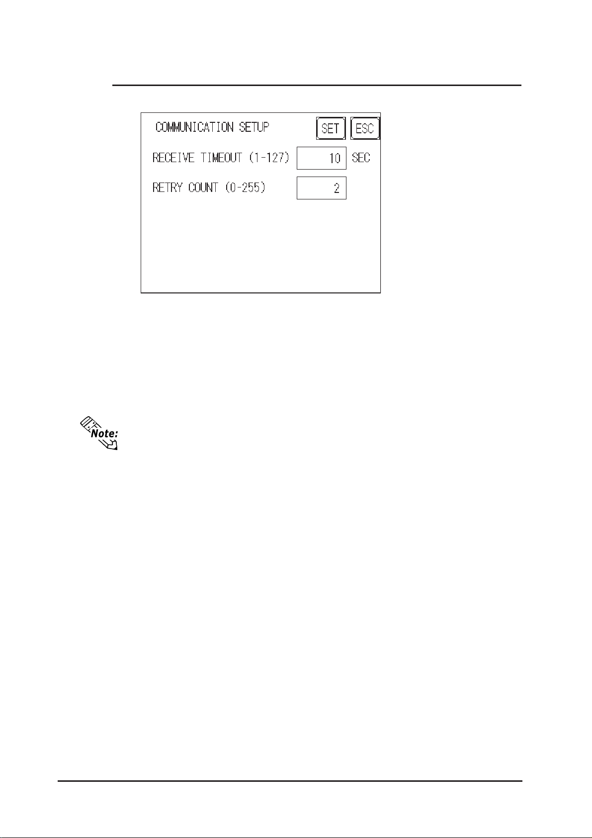
Chapter 6 - Initializing the GP
6.4.2 Communication Setup
RECEIVE TIMEOUT (1-127)
Sets the value used for the data reception timeout (PLC - GP).
If the cable is not connected, data communication will Timeout in one second, regard-
less of this setting's value. The default is "10" seconds.
If you transfer screens when a PLC communication error has occurred and the
error is not yet cleared, and the RECEIVE TIMEOUT value is set to 30 seconds
or more, an error message may appear on your personal computer.
RETRY COUNT (0-255)
Designates how many times the GP tries to send data to the PLC when a PLC communication error occurrs. An Error Message will appear on the GP after the GP tries to
send data to the PLC the number of times set by this option. The default is "2".
6-12
GP-2300/2301 Series User Manual
Page 82
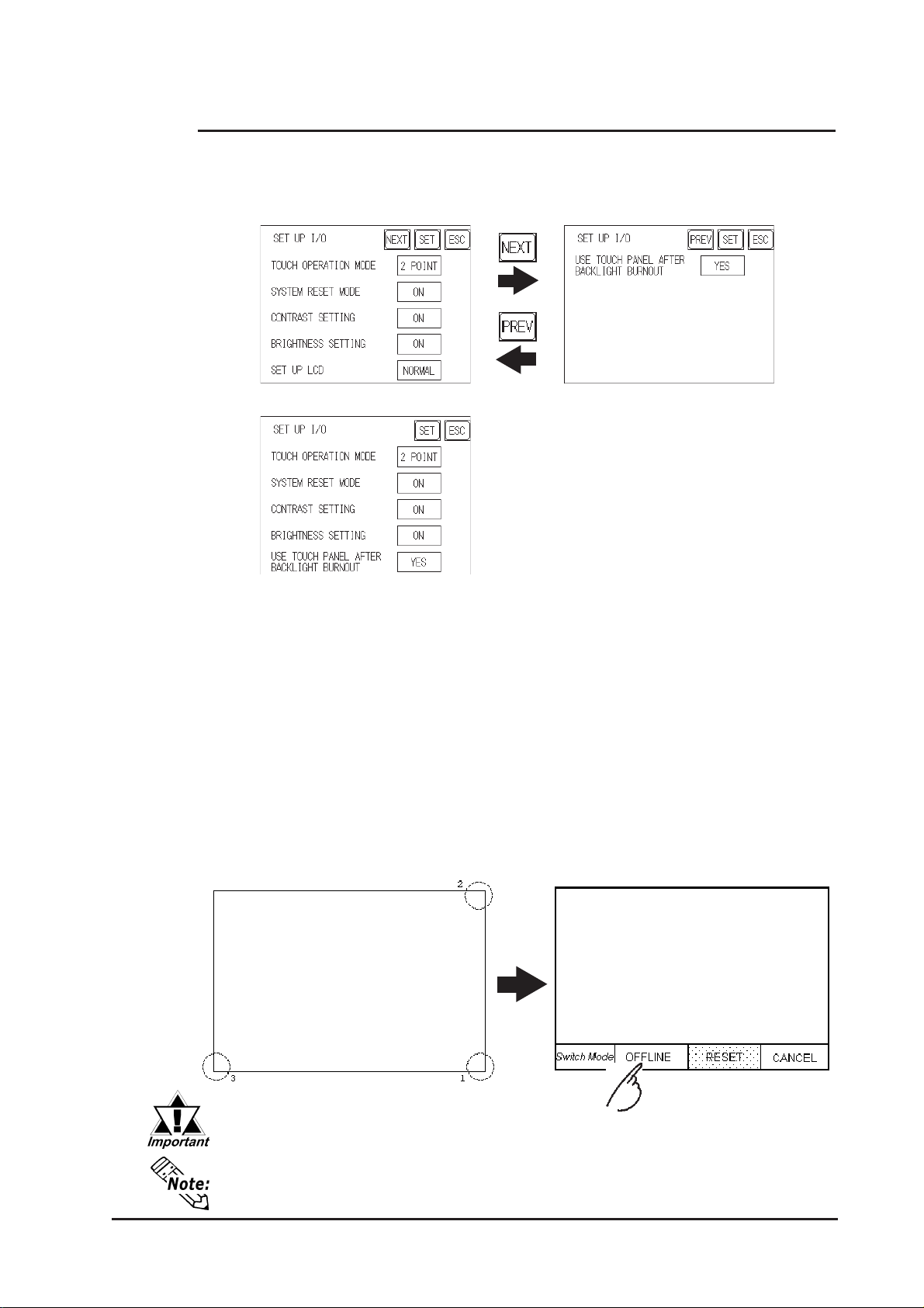
Chapter 6 - Initializing the GP
6.4.3 Set Up Touch Panel
T ouch operation and Force Reset setup, and Display Device adjustments are made
here. There may be diffrences on these settings depending of the GP type.
GP-2300L/GP-2301L Setup Screen
GP-2300S/GP-2300T/GP-2301S/GP-2301T Setup Screen
TOUCH OPERATION MODE
Designates either One Point, T wo Point or No Slide. When No Slide is selected,
dragging one's finger across the touch screen will elicit no screen response, and only
individually selected points will register.
SYSTEM RESET MODE
Designates whether to display or hide the Menu Bar. The Menu Bar can be displayed
using the following procedure when "ON" is selected.
Steps to run SYSTEM RESET
While pressing down on the bottom right corner (1) of the screen, press the upper
right corner (2). At the same time, press the bottom left corner (3) to enter the
FORCE RESET Operation. T o activate Reset, press the RESET button, to transfer
to OFFLINE Mode, press OFFLINE.
FORCE RESET can occur during either RUN mode or OFFLINE mode.
• The SYSTEM RESET mode cannot be entered while the GP is starting up.
• Entering SYSTEM RESET is possible even when RUN operations
(PLC <—> GP communication) are not being performed.
GP-2300/2301 Series User Manual
6-13
Page 83
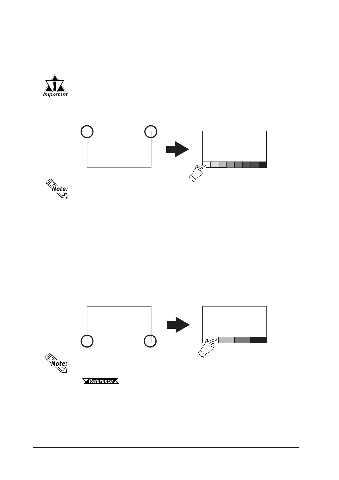
Chapter 6 - Initializing the GP
CONTRAST ADJUSTMENT
When this option is set ON, CONTRAST ADJUSTMENT s can be made through
touch input. (The GP-2300T/GP-2301T unit is not equipped with CONTRAST ADJUSTMENT feature.)
Be sure to press the GP corners in the order shown. If only corner (2) is
pressed OFFLINE mode will start.
While pressing the upper right hand corner (1) of the screen, press the upper left corner
(2) to enter CONTRAST ADJUSTMENT mode. Press the desired setting and the
screen's contrast will change accordingly .
21
Bright Dark
• To end CONTRAST ADJUSTMENT mode, touch anywhere on the screen,
except the bottom section.
• CONTRAST ADJUSTMENT mode cannot be entered while waiting for GP to
start up.
• CONTRAST ADJUSTMENTs can be made even in the middle of RUN mode
(PLC<-->GP communication).
• Regardless of a normal and reversed display, the left side of the contrast
adjustment bar, displayed at the bottom area of the screen, is always "Bright".
BRIGHTNESS ADJUSTMENT
When set to ON, BRIGHTNESS ADJUSTMENT can be performed via touch input.
Press the bottom left corner (2) of the screen while holding down the bottom right
corner (1) to enter BRIGHTNESS ADJUSTMENT mode. T ouch the left-side of the
bar to brighten the display; touch the right-side of the bar to dim the display . This unit
has four levels of adjustment.
Bright Dark
21
6-14
• With the GP units, reducing the display brightness may cause flicker. Adjust it
by changing the display device settings.
6.4.4 DISPLAY DEVICE SETTINGS
• To end BRIGHTNESS ADJUSTMENT mode, touch anywhere on the screen,
except the bottom section.
• BRIGHTNESS ADJUSTMENT mode cannot be entered while the GP is
starting up.
• BRIGHTNESS ADJUSTMENT can be used even during RUN mode
(PLC<-->GP communication).
• Regardless of a normal and reversed display, the left side of the contrast adjustment bar, displayed at the bottom area of the screen, is always "Bright".
GP-2300/2301 Series User Manual
Page 84
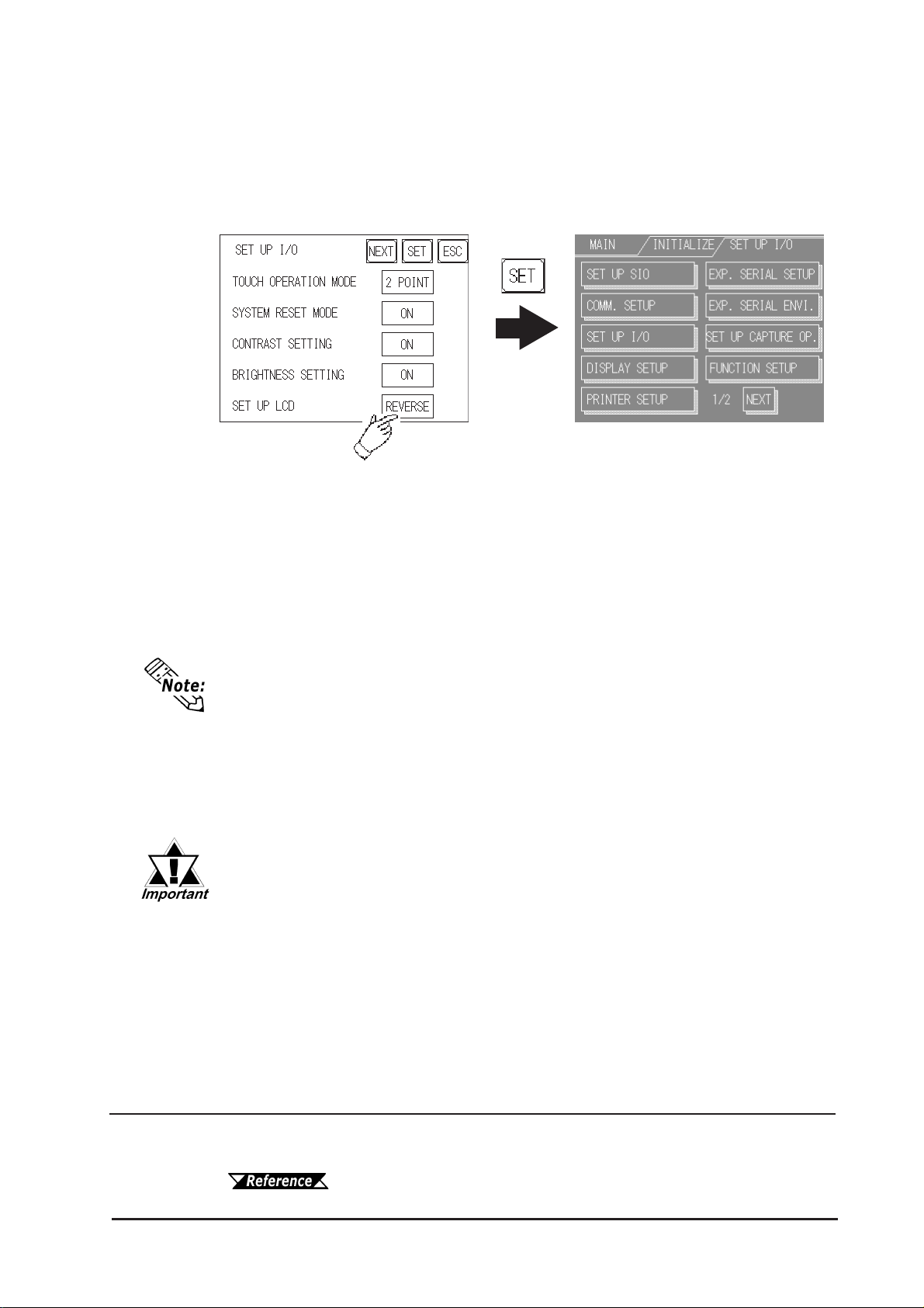
Chapter 6 - Initializing the GP
SET UP LCD (GP-2300L/GP-2301L only)
T o reverse the screen display colors, touch SET UP LCD on the SET UP I/O screen to
change the setting from "NORMAL" to "REVERSE", and then touch the "SET" key .
The display color will be reversed and the previous screen will reappear.
USE TOUCH PANEL AFTER BACKLIGHT BURNOUT
This option designates whether touch-operation is disabled or not when the backlight
burns out.
If this selection is set to [OFF], touch-operation will be disabled when the backlight
burns out, which prevents the GP from sending input signals to the PLC.
• When the backlight burns out, the Status LED's orange light turns ON, and the
System Data Area's "Status" bit 10
• If the [SYSTEM RESET] option is set to [ON], only "System Reset" can still
be performed by touch-operation in case of backlight burnout.
• If the backlight burns out when the GP is OFFLINE, touch-panel operation is
enabled, regardless of these settings.
*1
will turn ON.
Normally, the GP unit detects a backlight burnout by monitoring the
backlight's current flow, however, the GP may fail to detect this condition, depending on the type of backlight problem, and also the GP may
detect the condition before the backlight burns out.
*1 Bit +6 (when using the Direct Access method), and bit +11 (when using the
Memory Link method), will turn ON.
GP-PRO/PBIII for W indows Device/PLC Connection Manual (included with screen creation software)
GP-2300/2301 Series User Manual
6-15
Page 85
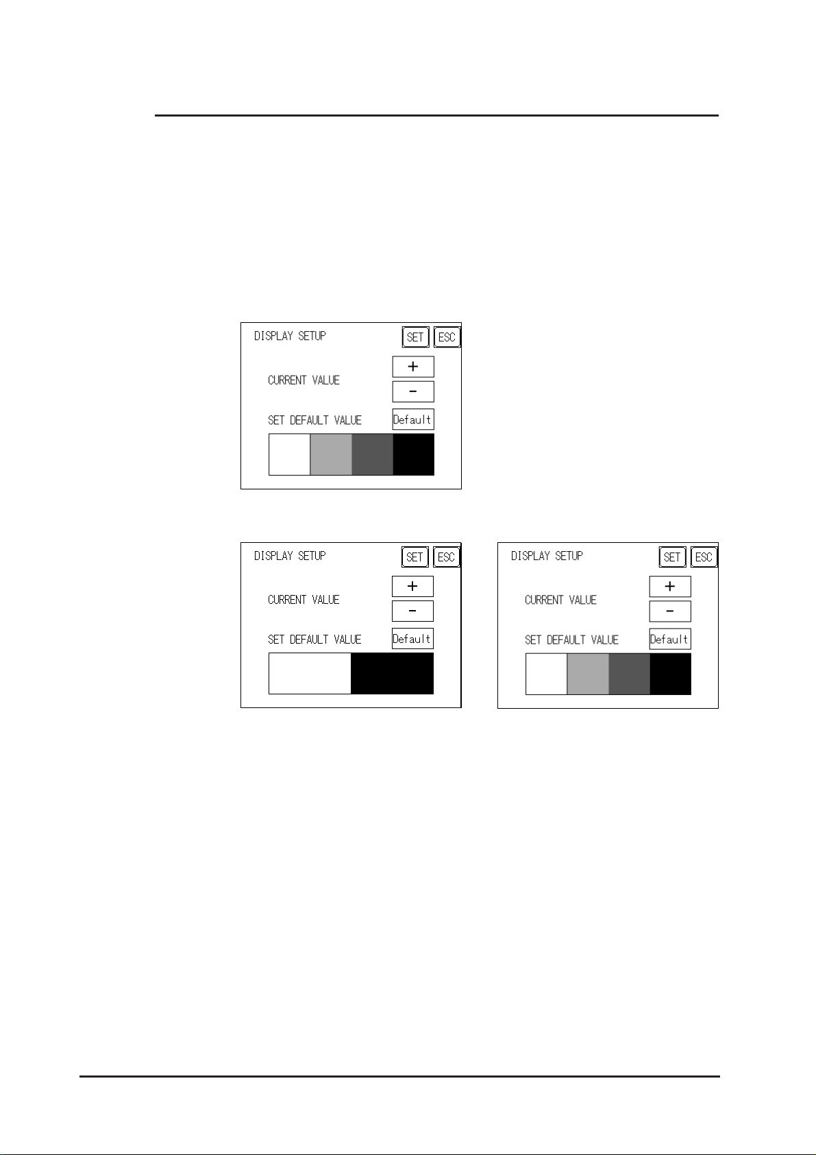
Chapter 6 - Initializing the GP
6.4.4 Display Setup
The GPs screen may flicker, or there may be shadows appearing on extended display lines
on the LCD surface. In the case where the GPs ambient temperature becomes high, and
its current brightness level is set to low , this effect may be more pronounced. This phenomenon is however, a common attribute of LCDs and is not a defect. T o solve this, use this
setting for adjusting the GPs brightness. (The GP-2300T/GP-2301T unit is not equipped
with DISPLA Y SETUP feature.)
• STN color LCD (GP-2300S/GP-2301S)
• Monochrome LCD (GP-2300L/GP-2301L)
<When using 8 levels of gray> <When using Black and White>
CURRENT VALUE
T o solve the above problem, touch "+" or "-" to adjust the brightness. Y ou can check
the actual brightness in the preview field at the bottom of the screen. From the default
value of "0" there are 18 "+" levels and 2 "-" levels available.
SET DEFAULT VALUE
If you touch "Default", the setting returns to "0".
6-16
GP-2300/2301 Series User Manual
Page 86
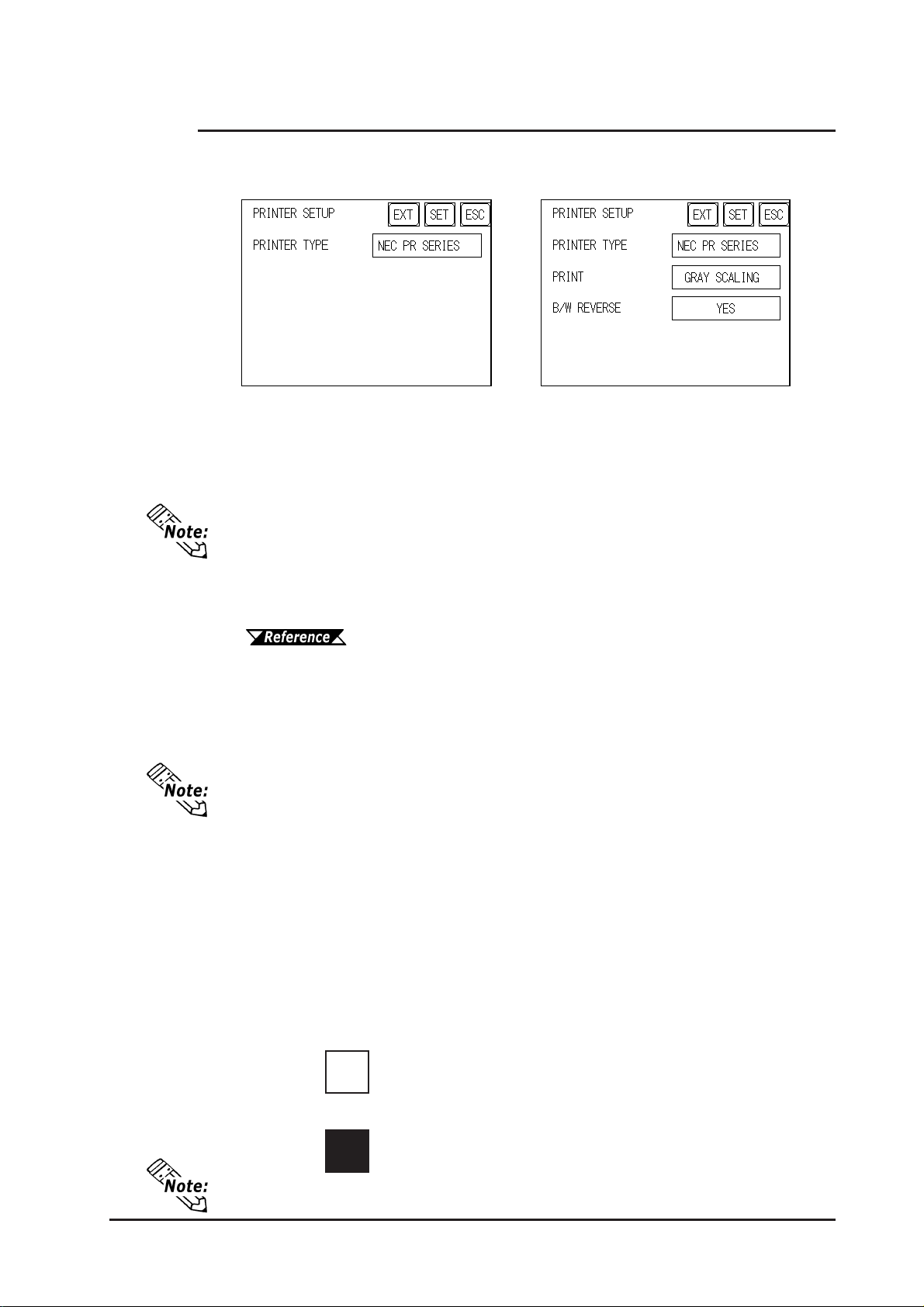
Chapter 6 - Initializing the GP
6.4.5 Set Up Printer
This setting is used to designate the type of printer that will be connected to the GP .
(Only GP-2300 Series units.)
GP-2300S/2300T Setup ScreenGP-2300L Setup Screen
PRINTER TYPE
Printers that are compatible with NECPC-PR201/PL , EPSON ESC/P24-J84(C), HP
Laser Jet PCL 4 commands, EPSON PM/Stylus (6-color ink) and EPSON Stylus (4color ink) printers can be used.
• There is no difference in the quality and printing speed between EPSON ESC/P
(High Speed) and EPSON ESC/P (High Quality) when printing out hard copy of
screen images from GP-2300S and GP-2300T.
• Using EPSON PM/Stylus (6-color ink), EPSON Stylus (4-color ink) printers,
GPPRO/PBIII for Windows Ver.6.2 or later is required. For details,
EPSON PM Series / EPSON Stylus Series
PRINT
T wo selections [GREY SCALING] and [COLOR] are available. If you select [GREY
SCALING], the same pattern will be applied to:
• Blue and Green • Light blue and Red • Purple and Y ellow
GP-2300S and GP-2300T Only .
• Since HP LaserJet Series printers do not support color printing, be sure to
designate [GREY SCALING].
• With the [GREY SCALING] feature, printing patterns are reduced to 5 levels
of gray from 256 or 64 colors.
Colors that do not appear in the printout are ones that have been converted
to white.
B/W REVERSE
This setting is used for reversing the background and display color black/white color
attributes. When the color is reversed, the background color is printed as black and the
character color is printed as white. GP-2300S and GP-2300T Only .
<e.g.> When the background color is black and the display color is white.
When “BLACK/WHITE REVERSE” is selected.
A
When “BLACK/WHITE REVERSE” is not selected.
A
This setting is enabled only when a screen display is printed. Alarm or Recovery
data output is printed always as black, regardless of the setting selected.
GP-2300/2301 Series User Manual
6-17
Page 87
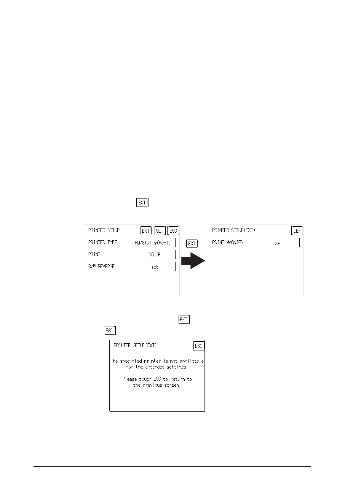
Chapter 6 - Initializing the GP
EPSON PM Series / EPSON Stylus Series
Restrictions for using EPSON PM / EPSON Stylus Series printers
• When printing using an EPSON PM/Stylus (6-color) or an EPSON Stylus (4-color)
printer, GP screen updating (tag processing, etc.) will be slower .
• Since OFFLINE Self-diagnosis (Printer I/F Check) is used only for ASCII code
output, it will not produce a correct printout.
• When screen data printout uses levels of shading, printout from these printers will
differ from a different type printer (PR201, etc.). This is because colors are recognized based on shading level patterns and not on the density of shading.
Extension Settings
When specifying EPSON PM/Stylus (6-color) or EPSON Stylus (4-color) as
"PRINTER TYPE", "PRINT MAGFNIFY" feature for screen data printout can be
specified in the [SET UP PRINTER (EXT-SET)] screen.
Specify either EPSON PM/Stylus (6-color) or EPSON Stylus (4-color) as "PRINTER
TYPE", and touch the key.
[SET UP PRINTER (EXT-SET)] screen will appear . Touch the desired magnification.
When specifying "PRINTER TYPE", except for EPSON PM/Stylus (6-color), EPSON
Stylus (4-color) printers, touching the key causes the following screen to appear.
T ouch the key, and the [SET UP PRINTER] screen will reappear .
6-18 GP-2300/2301 Series User Manual
Page 88
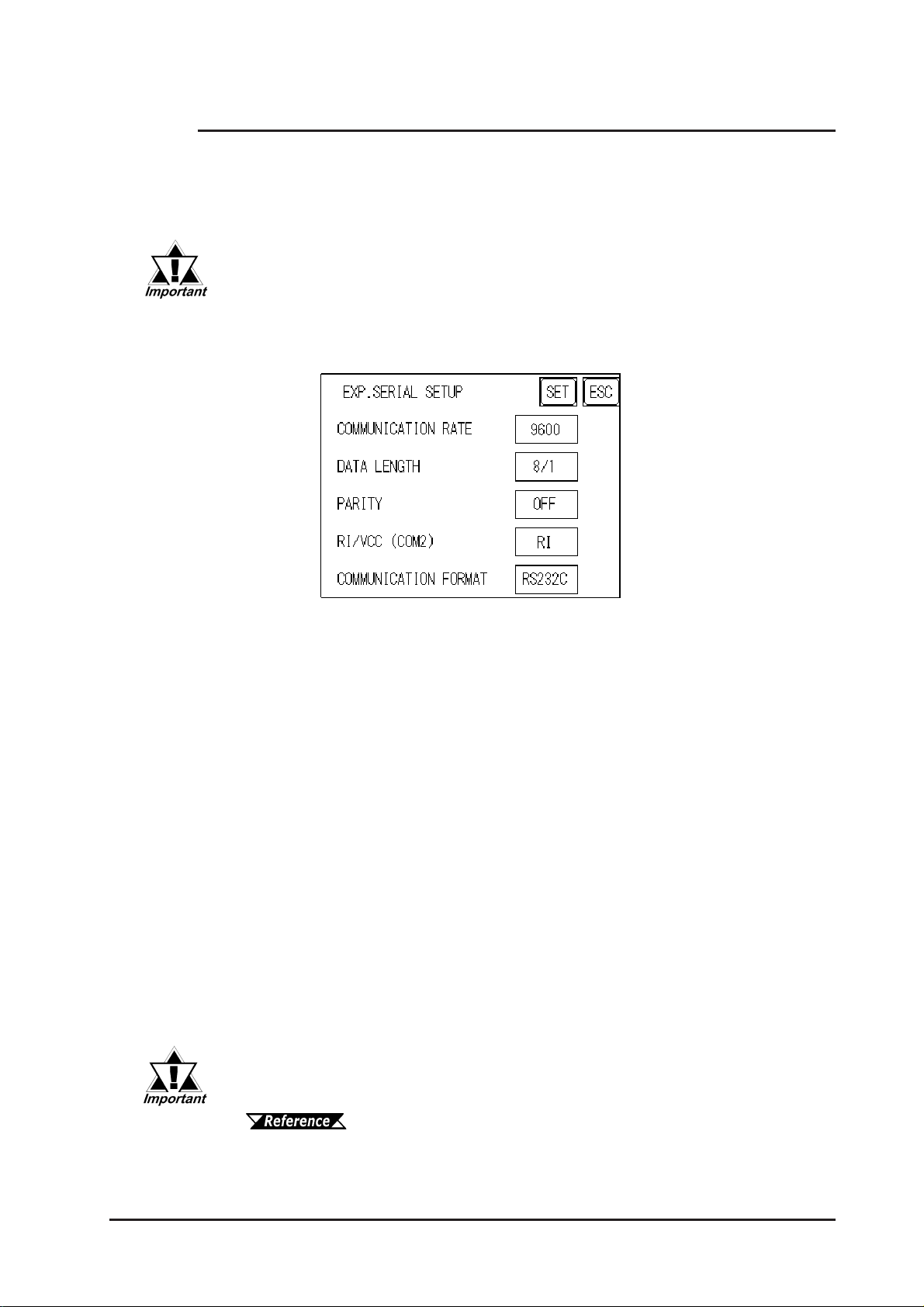
Chapter 6 - Initializing the GP
6.4.6 Expansion Serial Setup
The following explains the setup for communicating with a device connected to the
Expansion Serial Interface. This setup screen will not display unless the communication
protocol for the Expansion Serial Interface (specified with “SET UP EXP ANSION
SIO” of the GP screen creation software package) is transferred to the GP.
If you have selected "YES" for the [SERIAL I/F CHANGE] on the [COMMUNICATION PORT SETUP] screen, or "Yes" for the [Serial I/F Switch]
settings [Change Extend SIO Type] command, in the GP Screen Editor'
[Project] menu, enter all of the settings related to device communication
using the Extended SIO Script Protocol here, [EXPANSION SERIAL
COMMUNICATION SETUP] screen.
COMMUNICATION RA TE
The COMMUNICA TION RATE refers to the data communication speed, measured in
bits per second (bps), between the GP and the device connected to the Expansion
Serial Interface.
The supported communication rates vary depending on the connected device. Refer to
the instruction manual of the connected device for more information. The initial setting
varies depending on the communication protocol for the Expansion Serial Interface
being transferred.
DAT A LENGTH
Set the DATA LENGTH to 7-bit or 8-bit data, and set up also the STOP BIT as either
a 1-bit or 2-bit value.
PARITY
Set the parity to no parity (OFF), or an ODD or EVEN parity check.
RI/VCC
This setting designates if the Serial Interface's #9 pin is used for RI (Input) or for VCC
(Output).
VCC is only enabled in RUN mode, and if the mode is changed from RUN to
OFFLINE, this will change to RI. When an Expansion Serial protocol is not used, this
setting is fixed at RI.
There is a danger that the SIO circuit can be damaged if the VCC setting
is used and the Expansion Serial Interface's check tool is connected.
7.2.2 Self-Diagnosis - Details
COMMUNICATION FORMA T
Select one of the following options for the communication format: RS-232C, RS-422 (4
line), or RS-422 (2 line).
GP-2300/2301 Series User Manual
6-19
Page 89
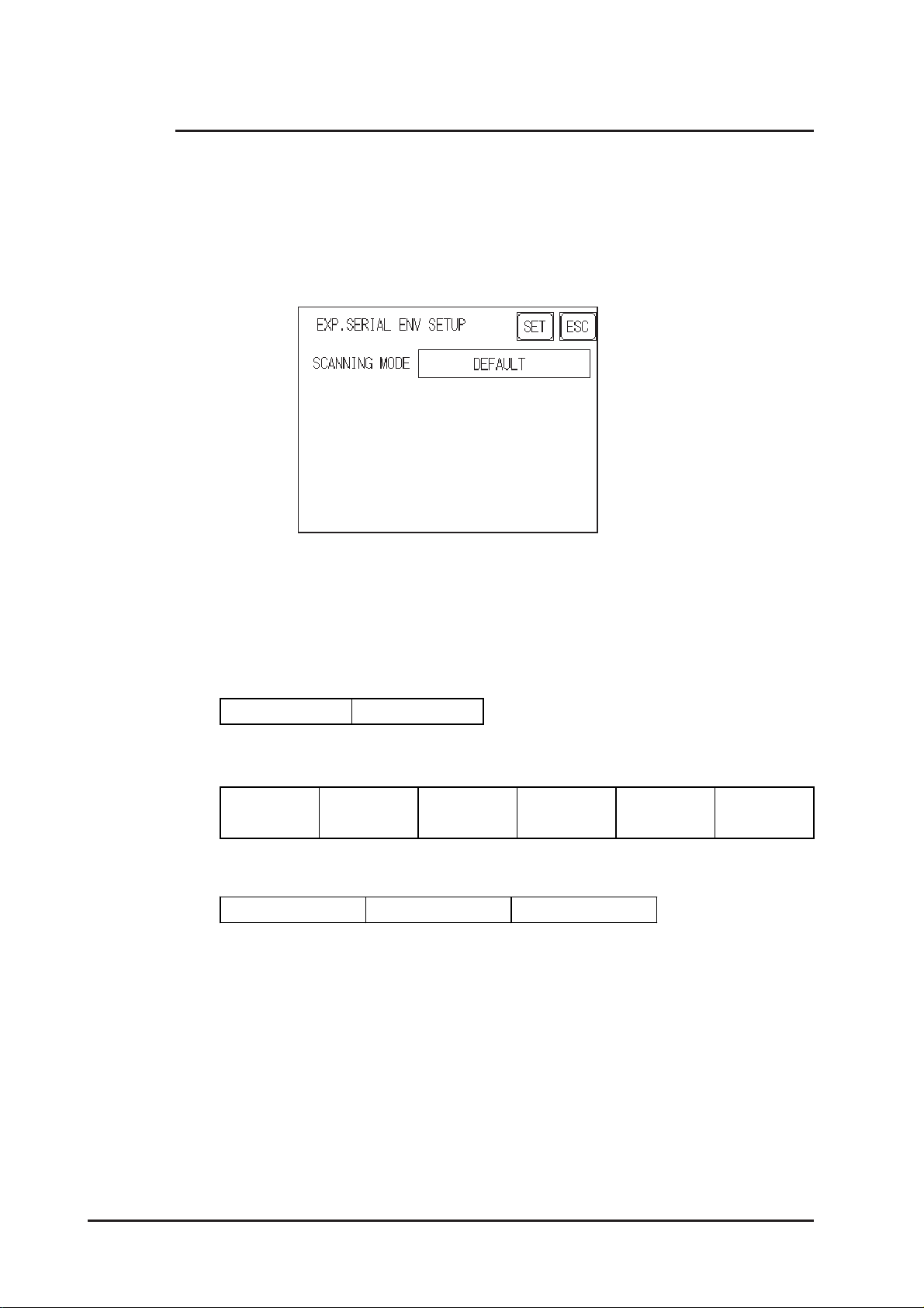
Chapter 6 - Initializing the GP
6.4.7 Expansion Serial Environment Setup
The following setting varies depending on the communication protocol for the Expansion
Serial Interface being transferred.
This section explains the case where “SERIAL CODE READER(LS)” is transferred.
Use this setting when a serial code reader is connected to the Expansion Serial Interface
to read serial code data. (Only GP-2300 Series units.)
SCANNING MODE
Select the SCANNING MODE according to the scanner settings.
The communication format for each mode is shown below:
• Standard
Code data Terminator ( CR)
• QR code scanner manufactured by Denso
Header (STX)
Code mark
(7 bytes)
No. o f digits
Code data
(4 bytes)
• Code scanner manufactured by T ohken
Header (STX) Code data Terminat or (C R + LF)
Terminator
(CR)
BCC
(7 bytes)
6-20 GP-2300/2301 Series User Manual
Page 90
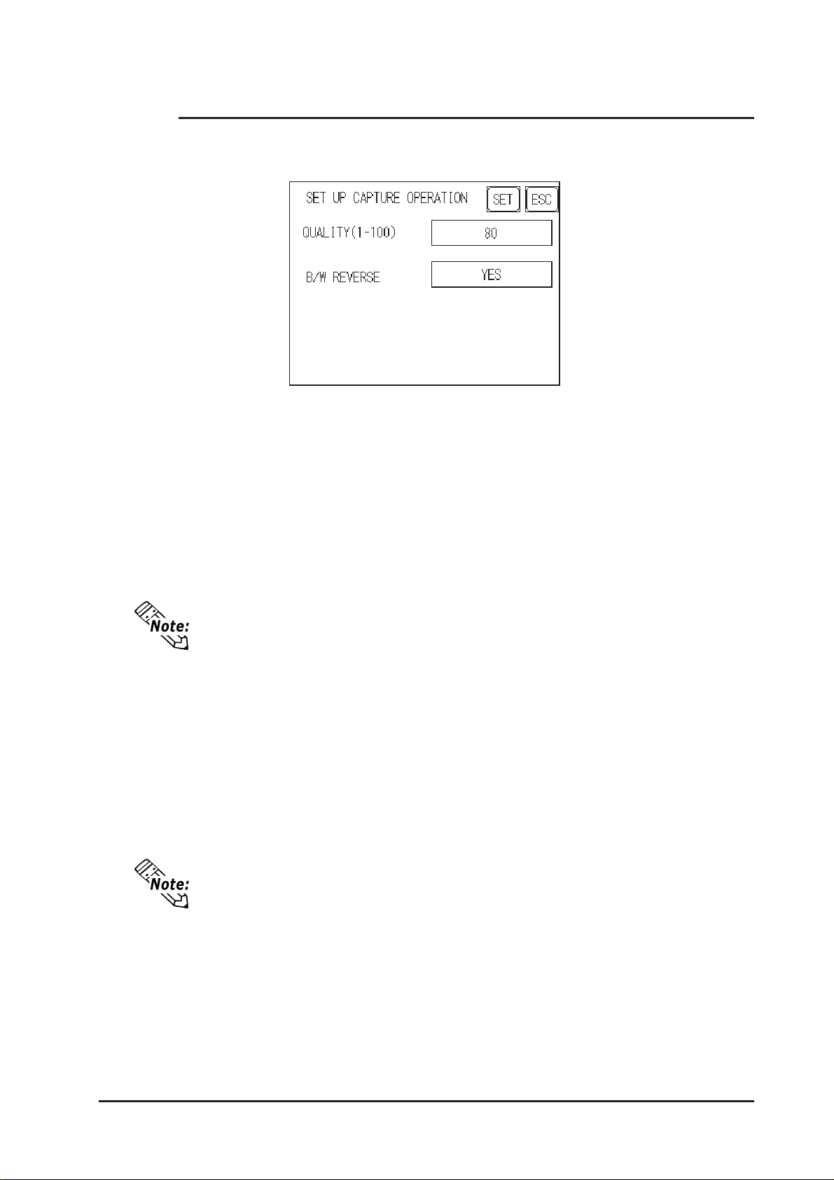
Chapter 6 - Initializing the GP
6.4.8 Set Up Capture Operation
Save the captured image of the GP's screen as a JPEG file in the CF Card.
QUALITY (1-100)
Sets the captured JPEG image quality . When the small value is set, the image file size
becomes small, but the image quality becomes worse.
B/W REVERSE
The white part in the image that is created in the screen creation program is reversed to
black, and the black part is reversed to white. The reversed screen is captured and
saved.
Only black and white are reversed. All other colors remain unchanged.
GP-2300L/GP-2301L (Monochrome LCD)
• When "B/W REVERSE" is "YES"
The displayed part (image data) is saved as black, and the non-displayed part is
saved in white.
• When "B/W REVERSE" is "NO"
The displayed part (image data) is saved as white, and the non-displayed part is
saved in black.
The monochrome LCD's GP saves image data as black in the CF Card, regardless
of the GP's reverse display setting.
GP-2300S/GP-2301S/GP-2300T/GP-2301T (STN/TFT Color LCD)
The Color LCD GP captures a B/W reverse image and saves it to the CF Card.
The white part of the image is converted to black, and the black part of the image is
converted to white. Only black and white colors are converted.
GP-2300/2301 Series User Manual
6-21
Page 91
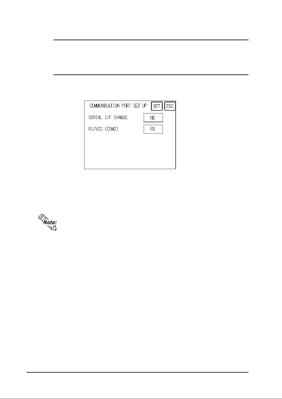
Chapter 6 - Initializing the GP
6.4.9 FUNCTION SETUP
Since the GP-2300/2301 Series units are not equipped with a function key , function
setup is not required.
6.4.10 COMMUNICA TION PORT SETUP
This screen allows you to set up the connection environment of the GP's communication
port.
SERIAL I/F CHANGE
Selecting "YES" designates that the communication used for the Extended SIO Script
Protocol starts at the Serial I/F (COM1). Also, the communication used for the device/
PLC starts at the Expansion Serial I/F (COM2).
In OFFLINE mode, the SERIAL I/F CHANGE setting is set to "NO".
• After selecting “YES”, enter all of the settings related to device communication using the Extended SIO Script Protocol, [EXPANSION SERIAL COMMUNICATION SETUP] screen. Enter all of the settings related to Device/
PLC communication, [SETUP SIO] screen.
• To use the “SERIAL I/F CHANGE” feature, the system of GP-PRO/PB III for
Windows Ver.6.2 or later is required to be transferred to the GP.
RI/VCC (COM2)
This setting designates if the Serial Interface's #9 pin is used for RI or for VCC.
6-22 GP-2300/2301 Series User Manual
Page 92
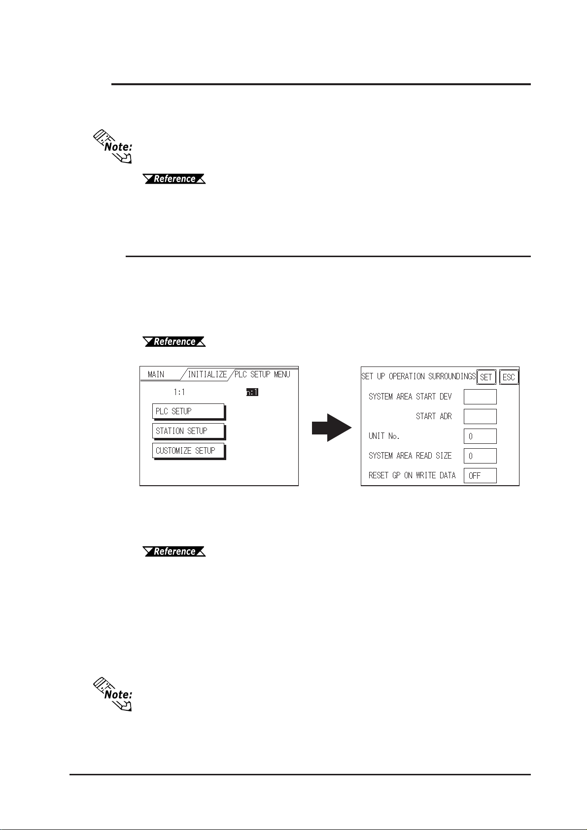
Chapter 6 - Initializing the GP
6.5 PLC Setup
Set up the GP System Area and the Unit number in this screen. Because 1:1 and n:1
GP connections utilize different settings, confirm your connection's needs before using
any settings.
• The screens that appear will depend on the PLC type you selected in the screen
creation software.
GP-PRO/PBIII for Windows Device/PLC Connection Manual (in-
cluded with screen creation software)
• When the GP-PRO/PBIII for Windows Ver 3.0 "Simulation" feature is used,
the OPERATION SURROUNDINGS menu cannot be used.
6.5.1 Set Up Operation Surroundings (1:1/n:1)
Enter the PLC System Data Area and the Unit Number settings here. The same options
are available for both 1:1 and n:1 (Multi-link) connections.
For an n:1 (Multi-link) Connection, System Data Area settings must be setup for each
GP connected to the PLC.
GP-PRO/PBIII for Windows PLC Connection Manual (included
with screen creation software)
STARTING ADDRESS OF SYSTEM DATA AREA
Setup the System Data Area's Start Address. Device addresses that can be allocated
will differ depending on the type of PLC used.
GP-PRO/PBIII for Windows Device/PLC Connection Manual (in-
cluded with screen creation software)
UNIT NO.
Enter the PLC UNIT number here. Check that it matches the one set up in the PLC.
SYSTEM AREA READING AREA SIZE (0-256)
When using a Block Display Trend Graph, setup the Reading Area Size (in word units)
to match the Trend Graph's data size. Use this feature when you wish to allocate the
Reading Area in the PLC Data Register (D), or Data Memory (DM).
If you are not using the Reading Area, leave the 0 default values intact. This will
allow you to perform high speed data communication.
RESET GP ON DATA WRITE ERROR
Designates the mode which enables you to cancel the error from the error display when
the Write error occurs.
GP-2300/2301 Series User Manual
6-23
Page 93
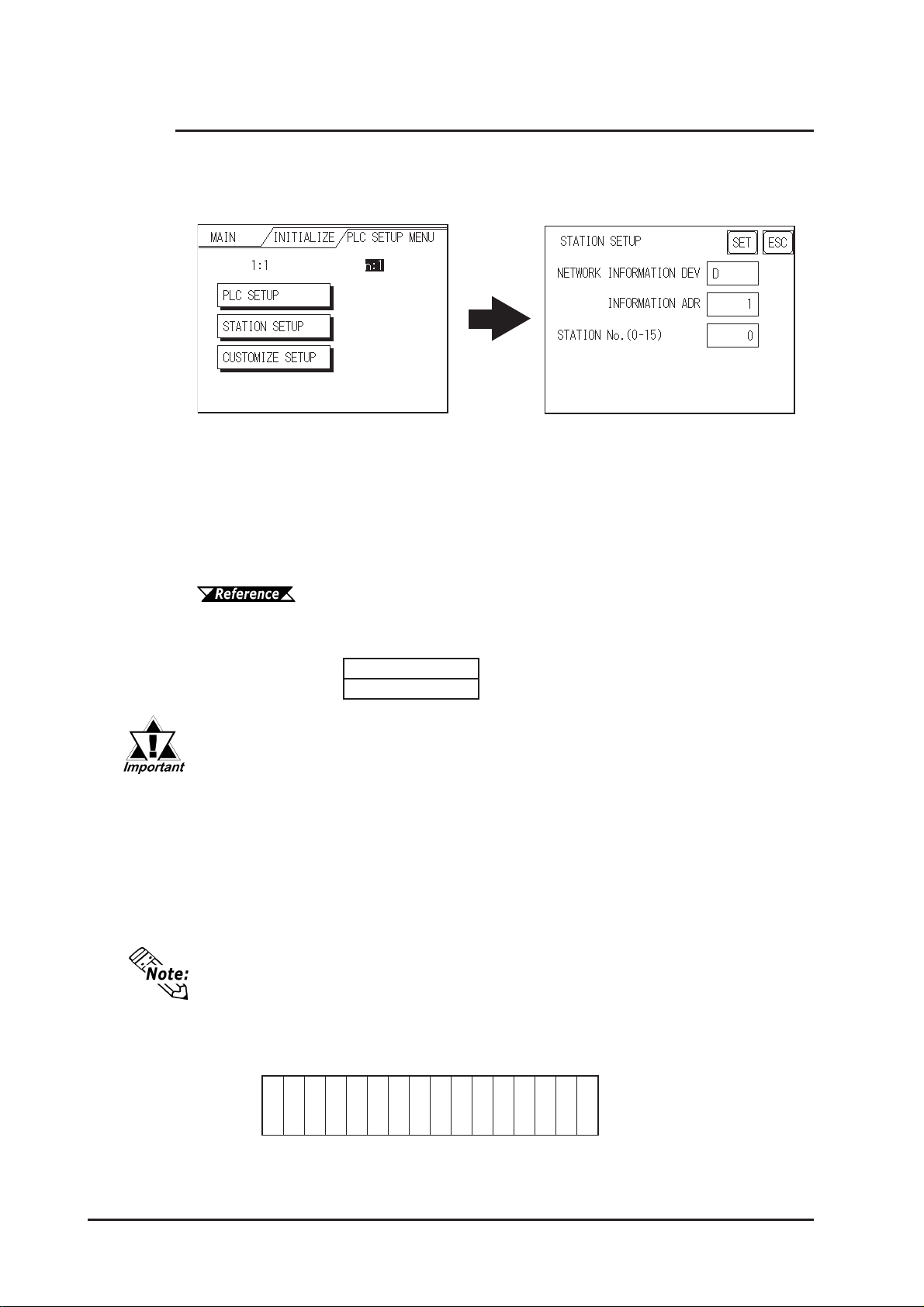
Chapter 6 - Initializing the GP
6.5.2 Station Setup (n:1)
The ST A TION SETUP, necessary for the n:1 (Multi-link) setup, checks whether correct
communications run with the connected GP System configuration.
NETWORK INFORMATION (DEV/ADR)
In the n:1 (multi-link) connection, the Network Information uses 2 words in its correspondences. These two (2) words consist of a Connection List and a V alidation List
(described later in this section). These areas are automatically allocated in the PLC's
Data Register (D) or Data Memory (DM). Select the Device No in the , then enter the
address No.
GP-PRO/PBIII for Windows Device/PLC Connection Manual (in-
cluded with screen creation software)
PLC Data Register
+0
Connection List
+1
Validation List
PLC→GP
GP→PLC
In the NETWORK INFORMATION ADR, setup the same address to all
the GP's connected to the same link unit. Furthermore, when there are 2
ports in the connected link unit, do not make them the same address.
Connection List
The word address for the Connection List sets up the number of GP's connected to
the PLC, which must be registered beforehand on the PLC side. When these GP's
are connected to the PLC, the corresponding PLC bit numbers for the particular GP
Stations (see below) should be turned on by the PLC.
When the GP is connected to the PLC, and the option of GP only correspondence
ends and OFFLINE mode is entered, the GP Station Number then turns the corresponding PLC bit OFF.
Bit 15 Bit 0
15 14 13 12 11 10 9 8 7 6 5 4 3 2 1 0
unitunit unit unit unit unit unit unit unit unit unit unit unit unit unitunit
6-24 GP-2300/2301 Series User Manual
Page 94
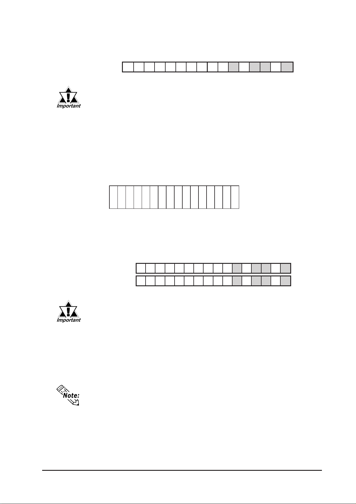
Chapter 6 - Initializing the GP
For example, when these 4 GP units—bit 0, bit 2, bit 3, bit 5—are connected, 002D
(h) is written here.
Connection List 002D (h)
0000000010110100
• Be certain to setup this data before running.
• Turn all bits not related to the GP OFF .
Validation List
This area responds to the correspondence from each connected GP. In the V alidation List, when the same bit numbers as the Connection List turn ON, the correspondence is accepted. The Station Numbers of the communicating GPs turn their
corresponding PLC bit number ON.
Bit 15 Bit 0
15 14 13 12 11 10 9 8 7 6 5 4 3 2 1 0
unitunit unit unit unit unit unit unit unit unit unit unit unit unit unitunit
If the correspondence between the GP and PLC is correct, the same value as in the
Connection List is written to the V alidation List.
For example, the value 002D (h) in the Connection List, setup as the 0 bit, 2 bit, 3 bit,
and 5 bit, writes to the V alidation List.
Connection List
Validation List
0000000000001111
0000000000001111
002D (h)
002D (h)
• When the Connection List and Validation List do not match, a COM-
MUNICATION ERROR occurs. Check the setup again.
• When changing the connection, first turn all the bits OFF.
STA TION NO. (0-15)
This is the setup for the GP Station Number mentioned above. The setup range is from
0 to 15, and the only other restriction is the GP ST A TION NO. must be unique in the
system. If STATION NO.'s are repeated, a COMMUNICATION ERROR occurs.
The STATION NO. is the number allocated to the particular GP unit. This number
is not related to the Link Unit Machine number.
GP-2300/2301 Series User Manual
6-25
Page 95
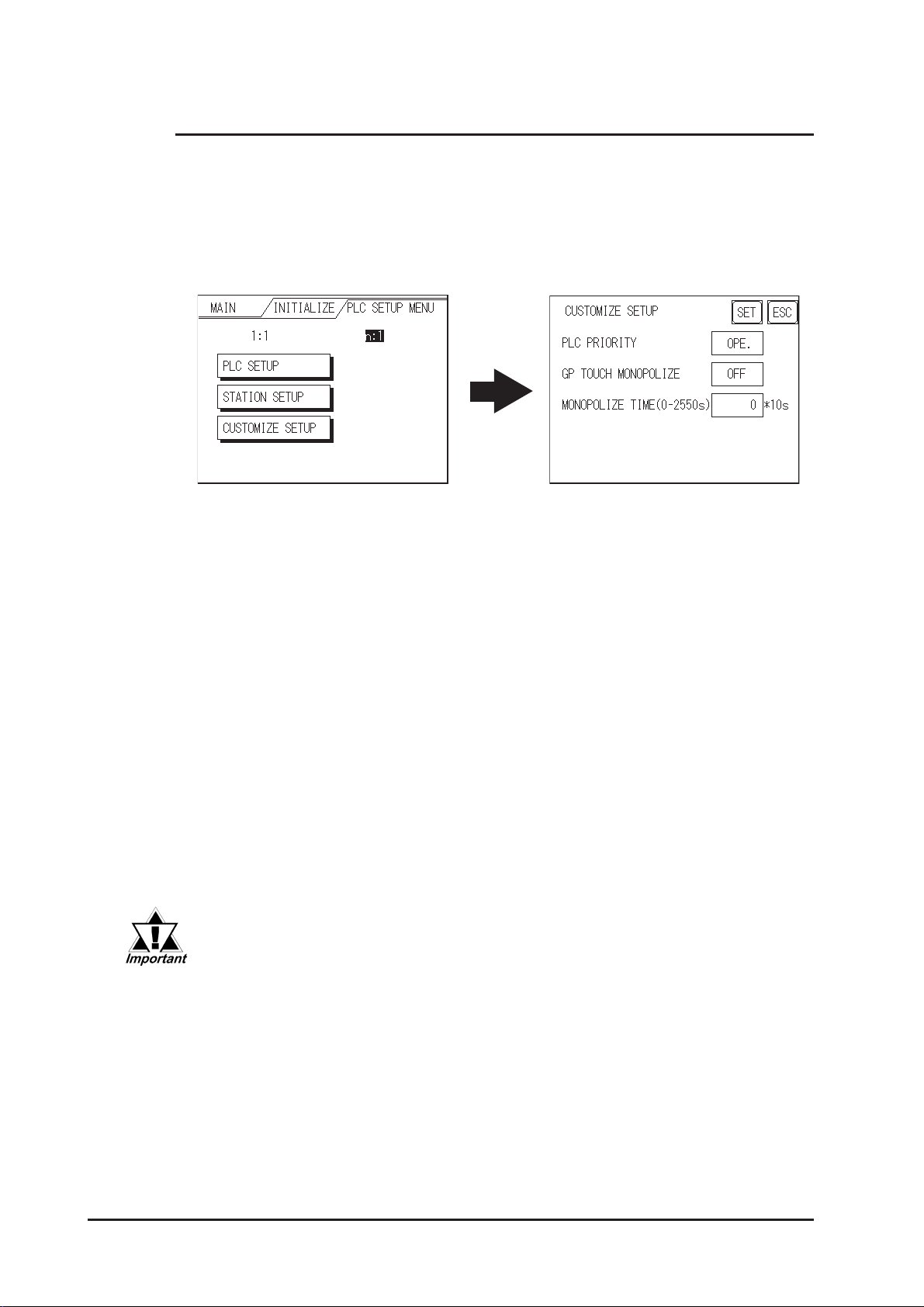
Chapter 6 - Initializing the GP
6.5.3 Customize Setup (n:1)
The Customize function modifies the n:1 (multi-link) connection's communication method
to make it more effective. T o run communication efficiently , the user should first determine whether they wish to have Operation or Display priority set for the GP . Based on
this, the communication response speed can be upgraded. (However, this also depends
on the screen information displayed.)
PLC PRIORITY
According to how the GP is used, select either Operation priority (OPE.) or Display
priority .
• Operation
Setup the GP to this option when using the GP mainly as an operation panel. As a
result, the GP will command better touch panel numeric input and switch response
times.
Leaving the GP in this mode does not drastically influence the touch panel operation
response time of other GPs. The screen display renewal cycle,however, will slow .
• Display
Setup the GP to this option when using the GP mainly as a monitor screen. The GP
will command a higher display speed as a result; however, the response time for the
touch panel's operations will slow .
• In a standard network setup, use the same setup for all connected
GP's.
• To increase the display speed, be sure the addresses used are consecutive addresses. When bit addresses are used, use consecutive
to the word units.
6-26 GP-2300/2301 Series User Manual
Page 96
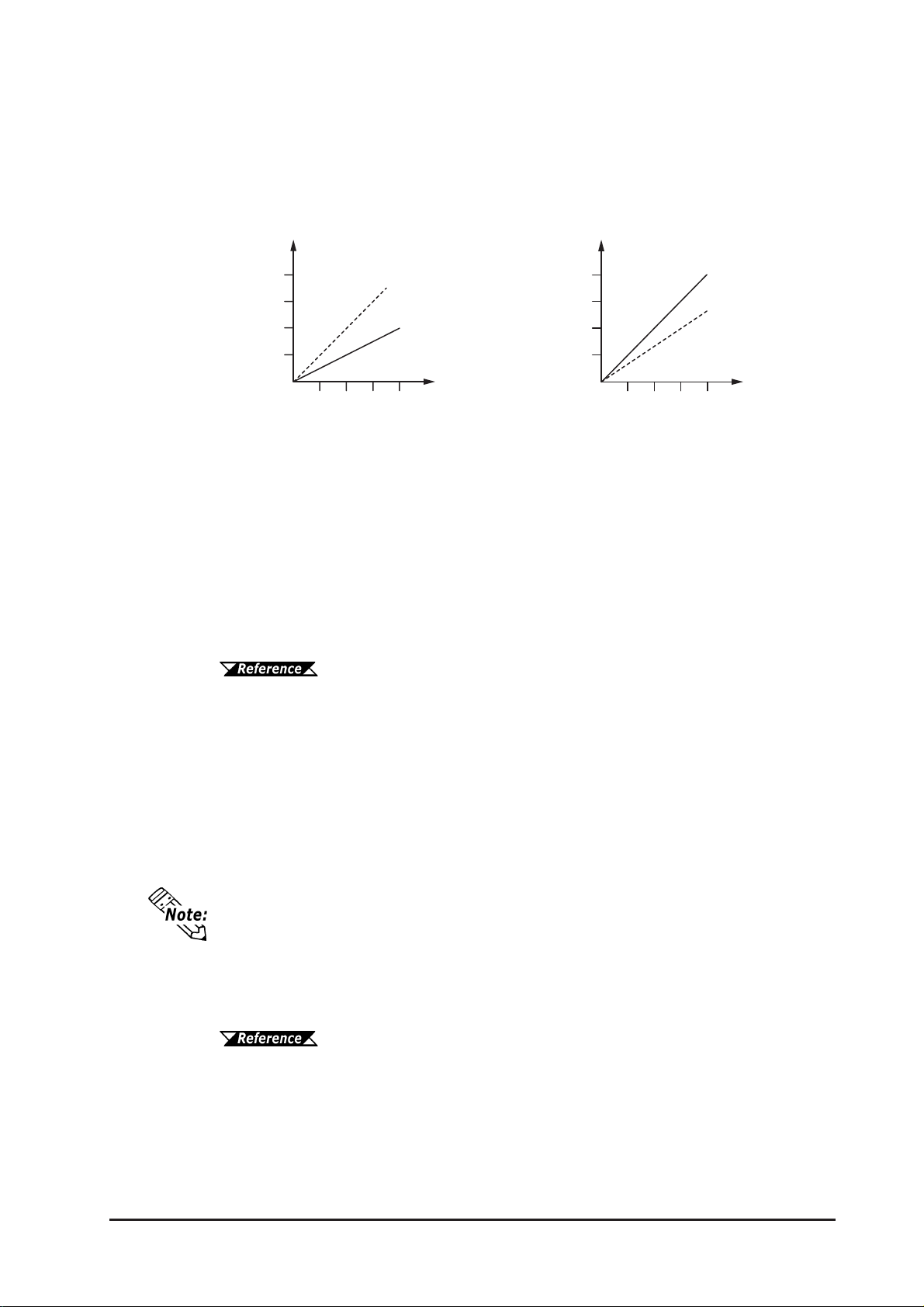
Chapter 6 - Initializing the GP
• Speed Difference between Display Priority and Operation Priority
When using the Mitsubishi Electric Corp. A3A PLC, with a scan time of 20ms with
consecutive addresses (80 words not included in the System Area), the difference in
reading speed is as shown in the following graphs.
TIME
Display Priority
0
OPERATION RESPONSE
GP TOUCH MONOPOLIZE
Operation Priority
# of GP
TIME
Operation Priority
Display Priority
# of GP
0
DISPLAY RENEWAL CYCLE
The monopolizing of touch panel use can be set ON or OFF . When you want to use
the PLC exclusively with a Momentary operation setup on the touch panel, turn GP
TOUCH MONOPOLIZE ON.
When this setup is ON, the touch panel uses the PLC exclusively whenever the momentary operation setup on the panel is pressed. In this way , you can use the inching
operation with a momentary switch. When you stop pressing the panel, exclusive use
ends.
GP-PRO/PBIII for Windows Device/PLC Connection Manual (in-
cluded with screen creation software)
MONOPOLIZE TIME (0 to 2550s)
This field controls the length of time for the monopolize process when no other touch
panel operations are performed. The Monopolize process begins when the System
Data Area's 7th bit of word address LS14 turns ON, and ends either when the bit turns
OFF , or when the time set here elapses.
• Pressing the touch panel in the middle of the monopolize process interrupts the
MONOPOLIZE TIME function, and ends exclusive use.
• When MONOPOLIZE TIME is set to 0, the monopolize function does not end
automatically.
For further imformation about the contents of System Data Area LS6
(status) and LS14 (control), r efer to GP-PRO/PBIII for W indows Device/PLC Con-
nection Manual (included with screen creation software)
GP-2300/2301 Series User Manual
6-27
Page 97
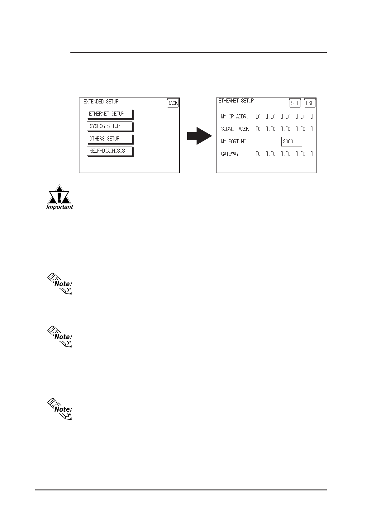
Chapter 6 - Initializing the GP
6.5.4 Ethernet Setup
This menu is for Ethernet settings. This information is used as setting data during GP
setup or screen transfer, or , if the Pro-Server software is used, for the 2-W ay Driver .
(Only GP-2300 Series units.)
• Enter the “ETHERNET SETUP” settings after receiving information
from your network's system administrator.
• Be sure to enter a unique IP address, not one used for other GPs or
by the host.
MY IP ADDRESS
Sets up the GP’s IP address. The IP address is 32 bits and designated in four 8-bit
units, entered in decimal.
To use Ethernet networking, click on [Initial Settings], [PLC Setup], [PLC Setup]
and [Ethernet Setup].
SUBNET MASK
Sets the subnet mask. If you are not using a subnet mask, designate “0”.
To use Ethernet networking, click on [Initial Settings], [PLC Setup], [PLC Setup]
and [Ethernet Setup].
MY PORT NO.
Sets the 2-W ay Driver Port No. using a value from 1025 to 65526. Starting from the
value entered here, a total of 10 consecutive ports can be used. The default setting is
[8000].
To use Ethernet networking, click on [Initial Settings], [PLC Setup], [PLC Setup]
and [Ethernet Setup] and select the corresponding Ethernet protocol Port No.
GATEWAY
Sets up the gateway’s IP address. Only a single gateway can be set up. If you are not
using a gateway , enter “0”.
6-28 GP-2300/2301 Series User Manual
Page 98
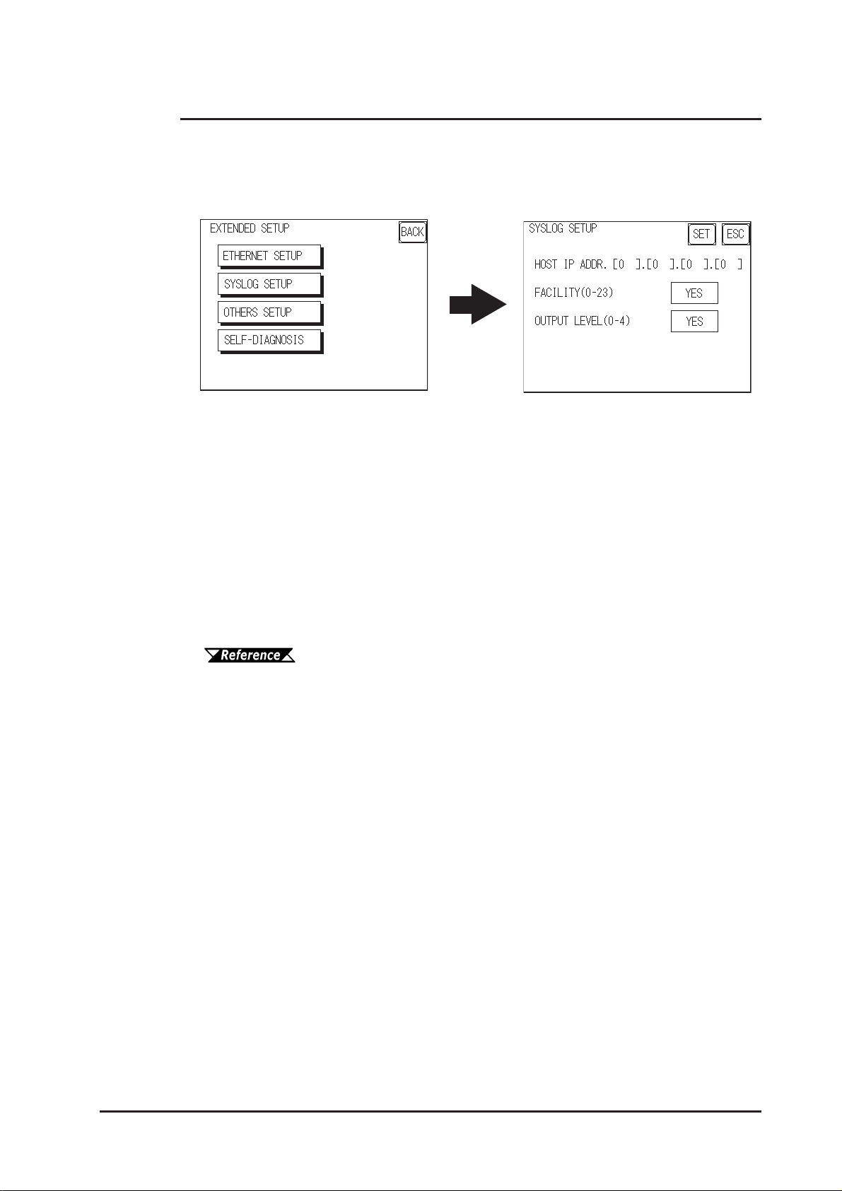
Chapter 6 - Initializing the GP
6.5.5 SYSLOG Setup
These settings are used for outputting 2-W ay driver’s operation logs. Therefore, if you
are not using the Pro-Server software, these settings are not necessary . (Only GP-2300
Series units.)
HOST IP ADDRESS
Sets up the IP address of the host computer, where the 2-Way driver’ s operation logs
will be output.
FACILITY (0-23)
Sets up the facility .
OUTPUT LEVEL (0-4)
Sets up the output level.
For details about Pro-Server and SYSLOG, refer to Pro-Server with
Pro-Studio for Windows Operation Manual (included in the Pro-Server with Pro-
Studio for Windows software package)
GP-2300/2301 Series User Manual
6-29
Page 99
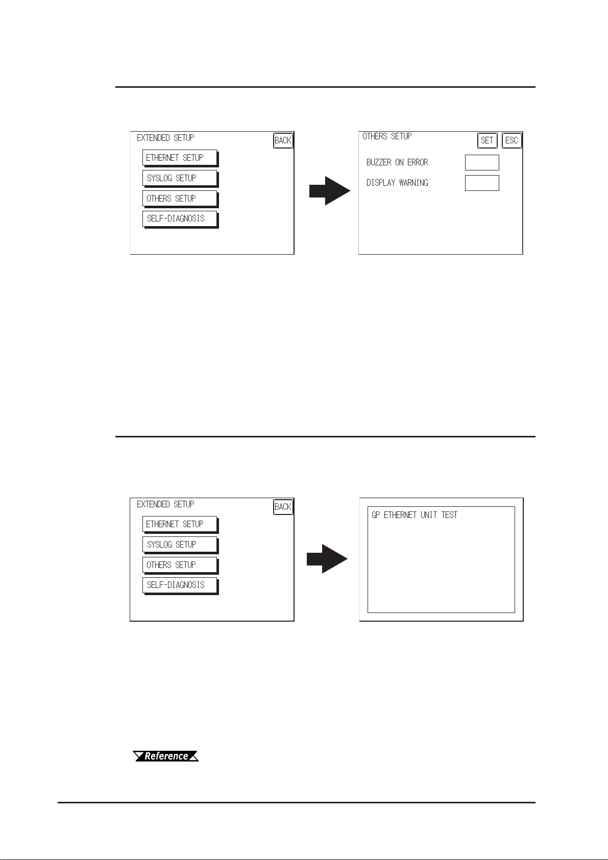
Chapter 6 - Initializing the GP
6.5.6 Others Setup
Designates the GP operation performed when a 2-W ay driver error occurs.
BUZZER ON ERROR
Enables/disables the buzzer sound output produced when an error related to the 2-W ay
driver operation occurs.
DISPLAY W ARNING
Enables/disables the warning message display used when an error related to the 2-W ay
driver operation occurs.
6.5.7 Self-Diagnosis
Runs the Self Diagnosis program for the Ethernet operation. The GP must be connected
to the Ethernet network prior to running this program. (Only GP-2300 Series units.)
When there is no error detected, the message “OK” will appear. If an error is detected,
the message “NG” will appear.
Be sure that this Self Diagnosis program is used only for the Ethernet operation. If you
wish to run the general Self Diagnosis program, use [Main Menu]’s [Self Diagnosis]
feature.
7.2 Self Diagnosis
6-30 GP-2300/2301 Series User Manual
Page 100
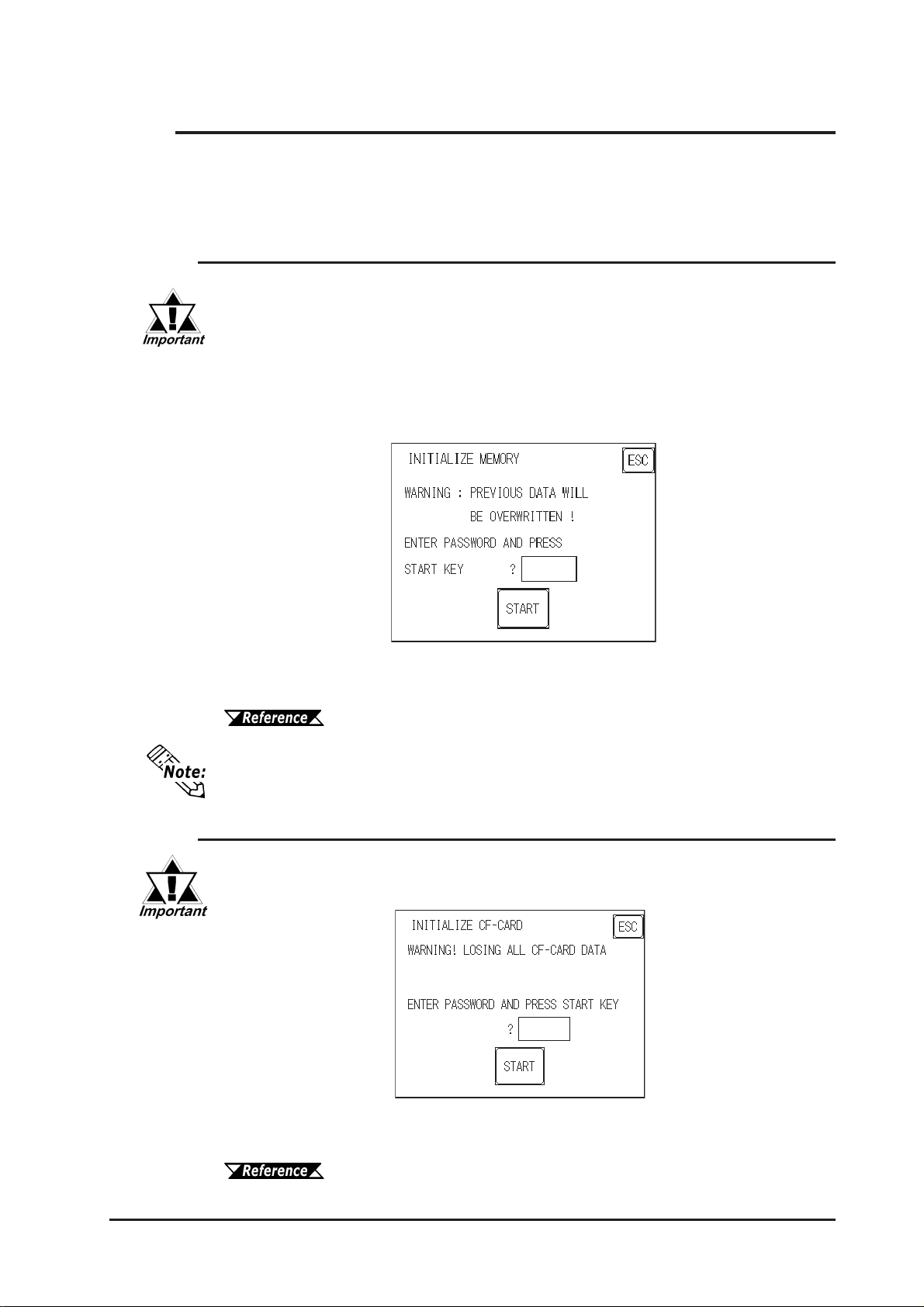
Chapter 6 - Initializing the GP
6.6 Initialize Internal Memory
This section explains how to initialize the GP’s internal data or a CF card inserted in the
GP . Select one of the menu items, [INITIALIZE MEMOR Y] , [INITIALIZE CF
CARD] and [CSV DA T A INDEX] selections in the [INITIALIZE MEMOR Y] menu.
6.6.1 Initialize GP Memory
This command erases all the GP screen data and initializes the GP's SRAM.
• You cannot cancel the Initialization procedure after pressing the Start
key.
• AIl backed up data in SRAM is lost.
• Initialization does not erase the SYSTEM SET UP, the SIO protocol, or
the internal clock settings.
T o initialize the GP internal memory , enter the common password 1101, or the password entered in the SYSTEM SET UP screen.
For details about entering the password’s numeric values, refer to
5.3 Initialization
The time required for Initialization is between 10 and 20 seconds.
6.6.2 Initialize CF Card
Deletes all data in the CF Card installed in the GP .
Initialization cannot be canceled once the ST AR T switch is touched.
Initializes the CF Card. Enter the common password “1 101” or the password you
designated in the “SYSTEM SET UP” menu.
For details about entering the password’s numeric values, refer to
5.3 Initialization
GP-2300/2301 Series User Manual
6-31
 Loading...