

Page 1
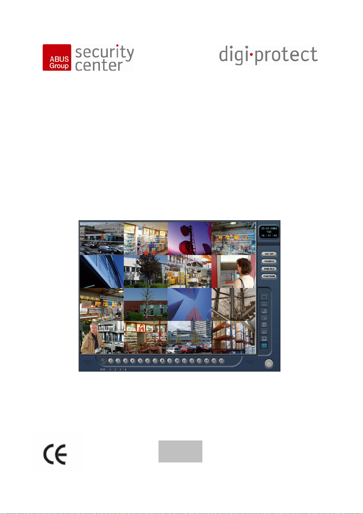
Digital surveillance system
Digi-Protect
User Manual
Incl. new Functions (Version 6.2x)
TV8800-
TV8813
Page 2

Contents
Contents ................................................................................................................................................59
Preface ..................................................................................................................................................61
Precautions........................................................................................................................................61
Scope of delivery...................................................................................................................................62
Installing hardware and software........................................................................................................... 63
System requirements.........................................................................................................................63
Installing the video card in the PC..................................................................................................... 63
Installation under Windows XP ...................................................................................................... 64
Installation under Windows 2000................................................................................................... 65
Camera connection............................................................................................................................65
Installing the software........................................................................................................................ 66
First steps with the digital surveillance system......................................................................................67
Overview of the live screen................................................................................................................ 67
Overview of the playback screen....................................................................................................... 69
Programming the DigiProtect system.................................................................................................... 70
Standard settings............................................................................................................................... 70
Recording........................................................................................................................................... 74
Schedule............................................................................................................................................77
Motion ................................................................................................................................................78
Color Control......................................................................................................................................78
PAN/TILT (dome camera) setup........................................................................................................ 79
Control User Access.......................................................................................................................... 80
Back Up.............................................................................................................................................. 82
Operating the digital surveillance system..............................................................................................86
Controlling dome (PTZ) cameras....................................................................................................... 86
Subfunctions of live screen................................................................................................................ 88
Views.............................................................................................................................................. 88
Recording Preview......................................................................................................................... 88
System Information (SYS-INFO).................................................................................................... 88
Update History................................................................................................................................ 89
Sending an automatic e-mail.......................................................................................................... 90
Message function........................................................................................................................... 90
Controlling playback........................................................................................................................... 91
Search bar...................................................................................................................................... 91
Playback bar................................................................................................................................... 91
Event filters..................................................................................................................................... 92
Date/time search............................................................................................................................ 92
Zoom function................................................................................................................................. 92
Zoom function................................................................................................................................. 93
Views.............................................................................................................................................. 93
Colour setup................................................................................................................................... 93
Live view......................................................................................................................................... 93
Subfunctions of playback screen....................................................................................................... 94
Back Up.......................................................................................................................................... 94
Search functions............................................................................................................................. 96
Data Lock ....................................................................................................................................... 97
Network connection............................................................................................................................... 97
Client Software................................................................................................................................... 97
Direct recording.............................................................................................................................. 99
Multi-server connections ................................................................................................................99
Web Client ....................................................................................................................................... 100
DigiProtect Searcher ........................................................................................................................... 101
Installing the alarm I/O card.................................................................................................................102
POS function ....................................................................................................................................... 103
Connecting the POS box .................................................................................................................103
Setting up the POS box ...................................................................................................................104
59
Page 3

Setup in surveillance system........................................................................................................... 104
Analysing transaction data...............................................................................................................106
New Functions – Version 6.20x........................................................................................................ 107
Card extension.................................................................................................................................107
Dual-monitor function.......................................................................................................................107
Saving the configuration file............................................................................................................. 108
Hybrid function................................................................................................................................. 108
Password manager.......................................................................................................................... 110
Power down mode........................................................................................................................... 111
Joystick control ................................................................................................................................ 111
E-mail authentication .......................................................................................................................112
60
Page 4

Preface
Dear Customer,
Thank you for purchasing this Digi-Protect video surveillance card. You made the right decision in
choosing this state-of-the-art technology, which complies with the current standards of domestic and
European regulations. The CE has been proven and all related certifications are available from the
manufacturer upon request. To maintain this status and to guarantee safe operation, it is your
obligation to observe these installation instructions.
Features
• Multi-channel recording in digital picture quality
• Variable memory capacity by recording video data on hard-disk
• Simple installation of hardware and software
• Wide-ranging recording, playback and search functions
• Control of pan/tilt cameras
• Simultaneous display of up to 16 channels
• Built-in motion sensor and surveillance of external sensors
• System access and control via network/Internet
Precautions
To avoid fire and injury,
please observe the following:
• Use the product in dry
• Make sure there is
• Do not expose the
• The device is designed
• The maximum humidity
• Ensure that the voltage
conditions only.
sufficient ventilation.
device to temperatures
less than -10°C or more
than 50°C.
for indoor use only.
must not exceed 90%
(non-condensing).
is disconnected when
performing work on the
device.
Please observe the following
regulations to ensure troublefree operation of your device.
• The digital surveillance
system is supplied with
electricity by the internal
power supply of the PC.
• The power supply unit must
be capable of supplying both
the system and the card.
• The card must be installed
as a fixture in the system.
General:
Improper or careless installation
work may lead to faults and poor
image quality. Therefore please
read the instructions very
carefully and follow the
installation instructions for lines
and components precisely.
The manufacturer reserves the
right to make technical
modifications at any time.
61
Page 5

Scope of delivery
Recorder card
Software
Watchdog cable
Cables
(not TV8802,TV8803,TV8805)
Operating instructions
(on CD)
62
Page 6
Installing hardware and software
System requirements
Operating system: Windows XP, 2000
Hard disk: Min. 200 GB for accident prevention certification
Mainboard: Mainboard with intel chipset 915… or 865G…
VGA: Radeon 9600 AGP, Radeon X550 PCIx
Number of drivers required and special hardware requirements:
Card Type SW-
Hardware requirements Driver Driver name
Typ
TV8800,
TV8801,
TV8802
TV8803,
TV8804
TV8805,
TV8806,
DF1000
DF1000
Celeron, 1.0GHz, 256 MB
RAM, 40 GB HDD
DF900
DF1500 Celeron, 1.7GHz, 256 MB
RAM, 120 GB HDD
DF2400 Celeron, 1.7GHz, 256 MB
RAM, 120 GB HDD
1 x Video
1 x Audio
2 x Video
2 x Audio
4 x Video
4 x Audio
TV8807
TV8809,
TV8810
TV8811 DF9400 Pentium 4, 2.4GHz, 512 MB
DF9000 Pentium 4, 2.4GHz, 256 MB
DDR-RAM, 200 GB HDD
1 Driver
1 Driver ALogics Ruby3
DDR-RAM, 200 GB HDD
NanoBT
NanoBT
NanoBT
ALogics Ruby3
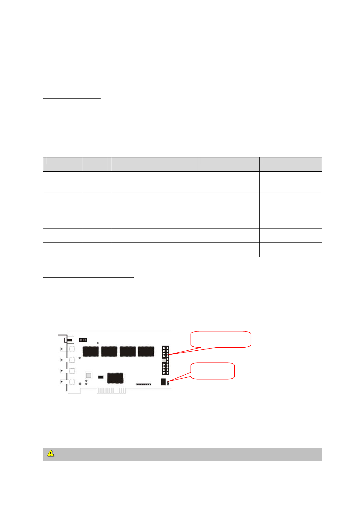
Installing the video card in the PC
1. Switch the PC off and pull the mains plug out. Open the PC and insert the DigiProtect card in a
free PCI socket. You may have to remove the blank on the rear of the PC. Fix the card using the
screws provided. Connect the watchdog cable correctly to the recorder card and the PC (PC reset
switch).
Alarm/sensor cable
Watchdog
2. Close the PC cabinet and switch on the PC. Windows starts hardware recognition and detects the
newly fitted DigiProtect card.
IMPORTANT: Install the hardware and drivers before the software.
63
Page 7
Installation under Windows XP
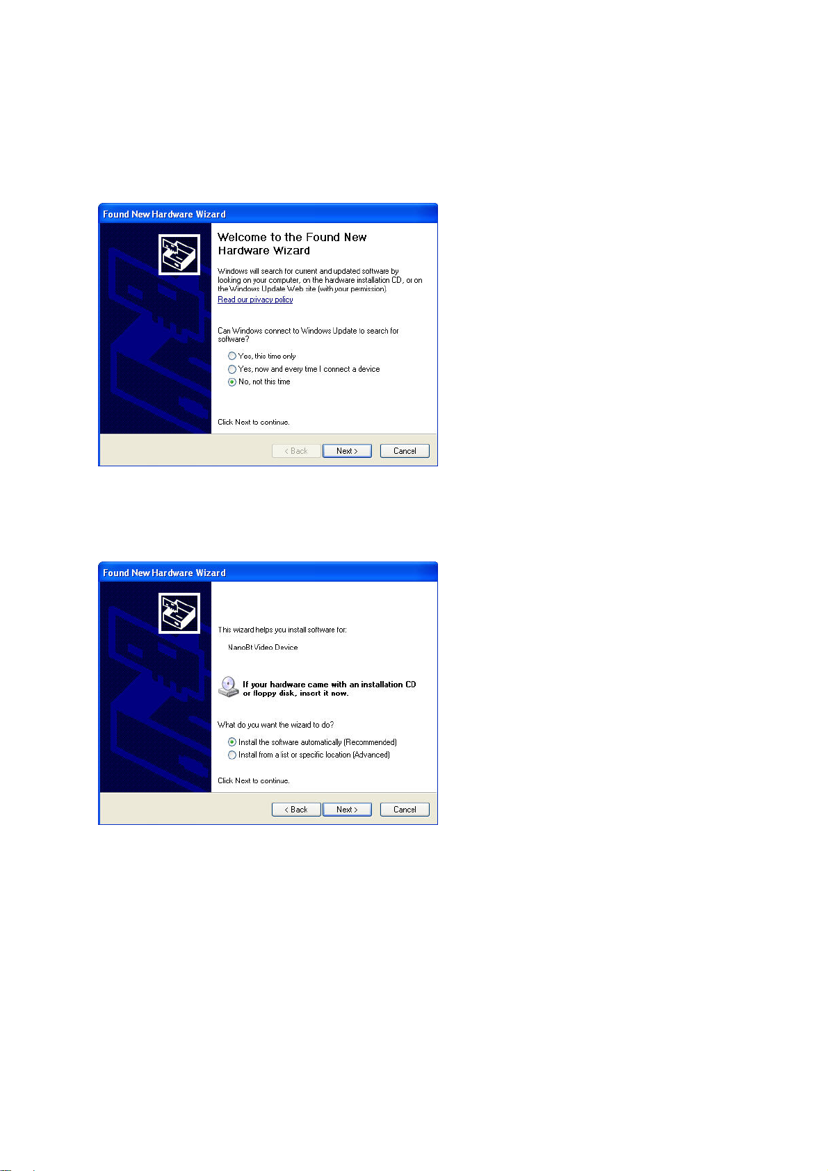
After Windows XP starts, the following window may appear:
Now place the DigiProtect software CD in the CD drive and select “No, not this time” to install drivers
from the CD.
The drivers are on the software CD under [CDROM]:\DigiProtect xxxx Server\DRIVERS
(e.g.: E:\DigiProtect 900 Server\DRIVERS).
Follow the installation instructions on the screen. If the system cannot find the drivers automatically,
make a link to the directory named above.
Note: Windows XP may display a message that the drivers are not signed. Select “Continue”.
The DigiProtect card driver supports Windows XP.
All required drivers (see table on page 7) must be correctly installed.
64
Page 8
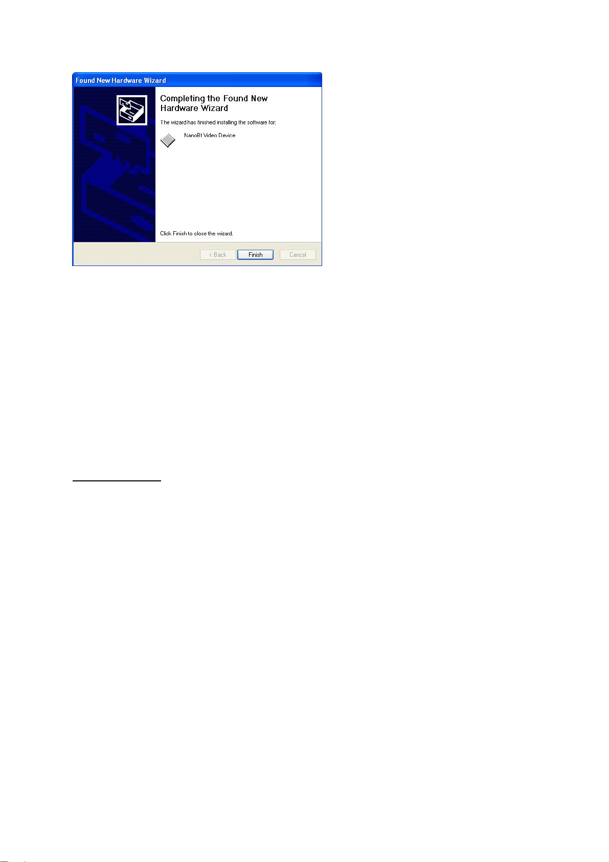
Press [Finish] to complete driver installation.
Installation under Windows 2000
To install the recorder card under Windows 2000, first open the Control Panel under [Start / Settings /
Control Panel]. Then open the Hardware Wizard under [System / Hardware / Hardware Wizard].
The drivers are on the software CD under
[CDROM]:\DigiProtect xxxx Server\DRIVERS (e.g.: E:\DigiProtect 900 Server\DRIVERS).
The new hardware is now searched for. When installing the drivers, make a link to the above-named
directory. Install all drivers and complete the installation correctly.
Camera connection
The pin assignment of the video inputs (BNC) is done either via the cable supplied or directly via the
BNC video inputs on the recorder card. Now connect your video signals to the recorder card.
65
Page 9

Installing the software
The CD contains the following applications:
DigiProtect Server software
DigiProtect Client
DigiProtect Searcher
Before installing the software, make the following settings on the PC:
1. Set the screen resolution to 1024 x 768 pixels, True Color 32 bit.
2. If the graphic card uses an overlay function, disable the function.
3. Disable the screensaver under [Control Panel / Display / Screensaver].
4. In this window, click [Energy Management]. Set [Turn off monitor], [Turn off hard disks], [Standby]
and [System standby] to “Never”.
Now install the DigiProtect Server software as follows:
1. Place the CD in the CD drive.
2. Select the directory for your card: “[CDROM]:\DigiProtect xxxx Server\” (e.g.: DigiProtect 900
Server).
3. Start Setup.exe in this directory. Follow the screen instructions to complete the installation. To
proceed to the next step of the installation, click [Next]. To return to the last step, click [Back].
Click [Cancel] to cancel the installation.
Important: During the installation, you are asked to select the correct video modulation type
(Europe: PAL). You also have to specify whether a DigiProtect audio card is installed and whether
the POS function (point-of-sale connection) is to be installed. You are asked whether you want to
install the standard or the UVV version of the DigiProtect software. To meet the accident
prevention certification requirements, the UVV version must be installed. The Standard-Version
includes the POS function (chash register function) and a minimize button additionally.
During installation, you may be asked to confirm editing of a read-only file (“ReadOnly File Detected”)
by the system. Click [YES].
4. Click [Finish]. Now double-click the DigiProtect Server icon on the desktop. Click [OK] to reboot
the computer. During the reboot, the digital surveillance system starts automatically.
66
Page 10
First steps with the digital surveillance system
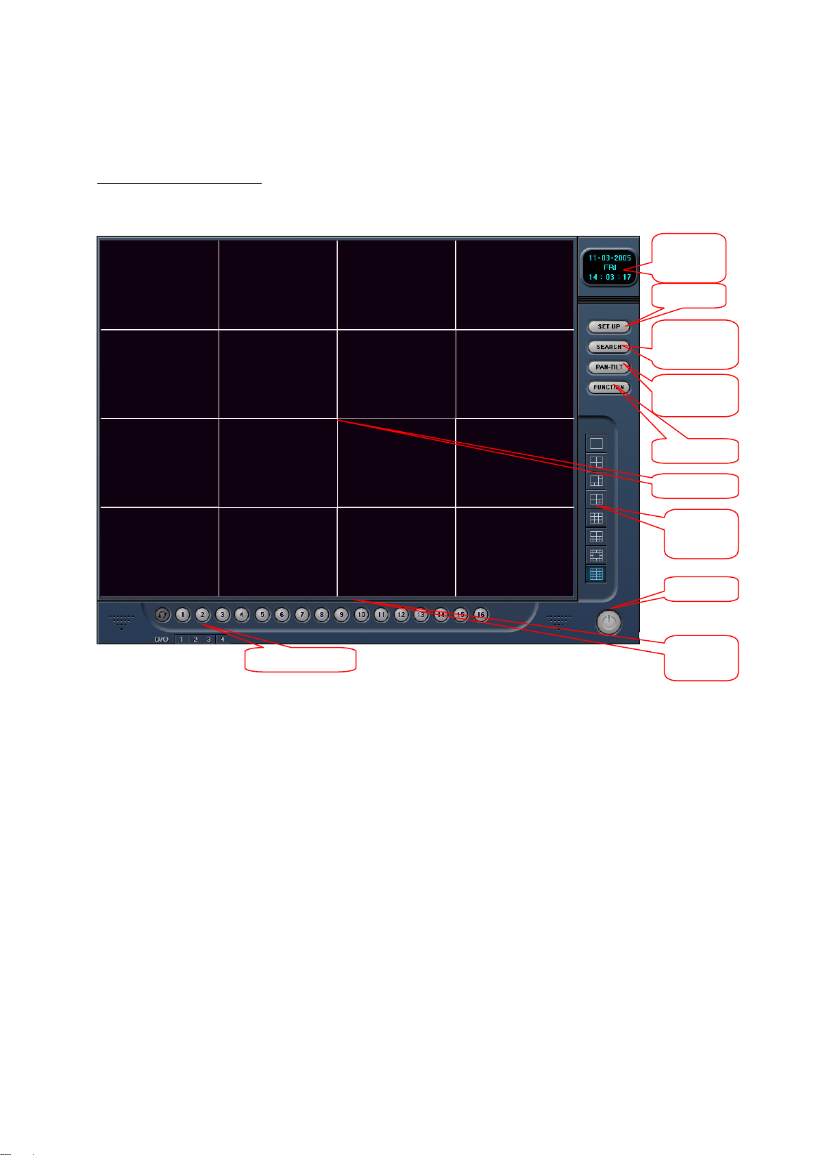
Overview of the live screen
After the software starts, an information window opens on the screen. Close it by clicking [OK].
Date/time
Setup
Playback
/Search
Dome
control
Function
Live video
Screen
division
Exit
Alarm outputs
Channel
selector
Setup: Here you can configure the digital surveillance system. Besides general settings,
you can set the following here: recording type, schedule, motion detection, pan/tilt
function, network and backups.
Playback: To play back recording video data you have a wide range of options for finding,
[Search] analysing and saving relevant video data.
Dome: For controlling connected dome cameras
Function: Useful functions such as preview, system info, history, network messages or auto-
email are available.
Date/time: Display of date and time
67
Page 11
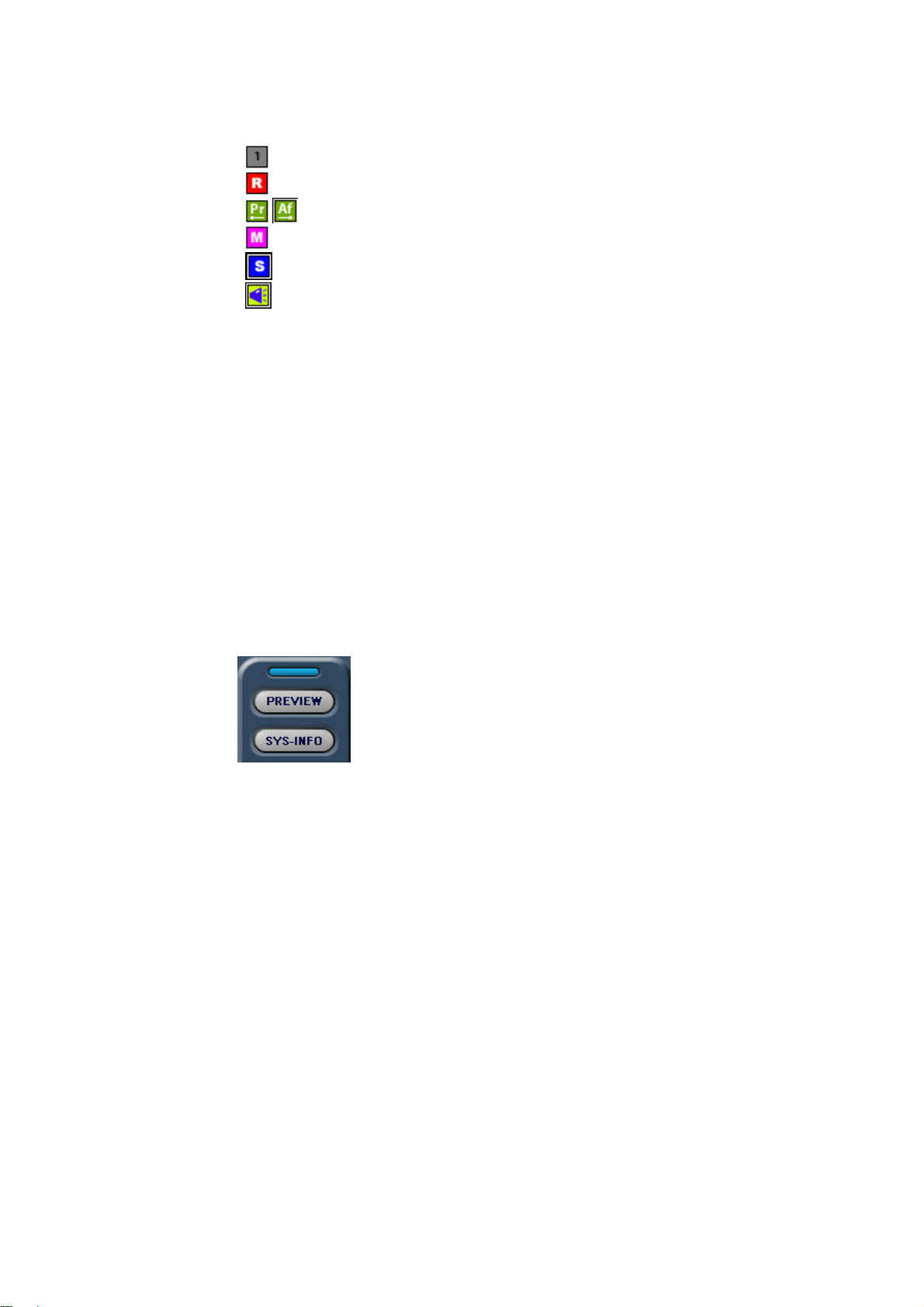
On-screen information: In the live view, various information can be displayed with the video picture:
Channel number
•
Normal (continuous) recording
•
•
Pre- (Pr) or post-event recording (Af)
Recording of motion event
•
•
Recording of sensor alarm event
•
Voice recording
Channel selector: Here you can select a specific channel or automatic channel sequencing.
Screen division: To view video pictures live, you can select either a single picture (full-screen) or up
to 16 pictures at a time (depending on your video card). You can move the channels
around in the live-video area according to your needs. To do this, left-click a live
video picture and keep the mouse button pressed. Now drag the video picture to the
desired live video area and drop it there.
Alarm outputs: Outputs 1–4 can be switched here manually (optional alarm I/O card TV8812
required; see the section “Installing the alarm I/O card” for fitting).
Exit: Button for exiting the digital surveillance system
Exit
submenus: Click the blue button above selection buttons to exit submenus at any time.
68
Page 12
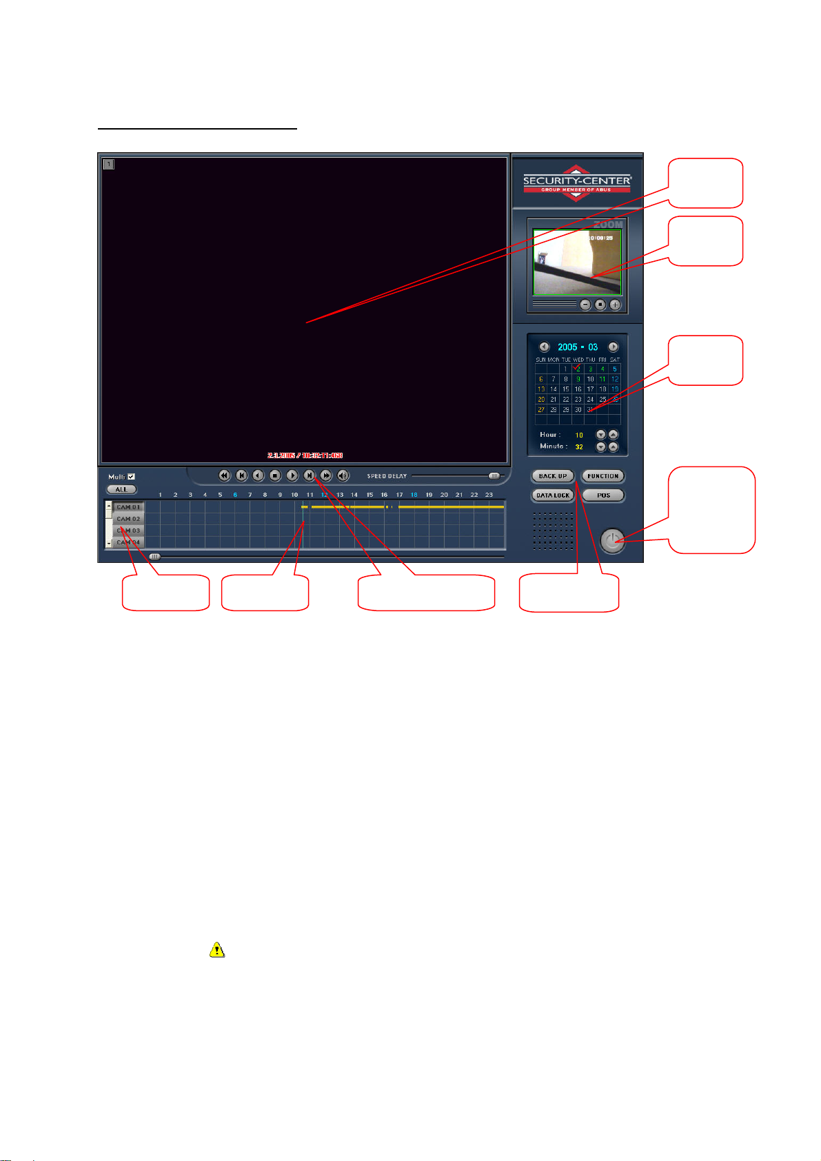
Overview of the playback screen
selector
Video
area
Video
zoom
Date/time
Exit
playback
screen
Channel
Search bar Playback bar
Functions
Search bar: This function gives you direct access to recorded video data. The data is displayed
as a coloured bar for each channel and according to recording type.
Channel selector: Buttons for activating/deactivating channels for display in the video area. The
channels are arranged automatically in the video area. For more than four video
channels, you can access the other video channels via the vertical scroll bar to the
right of the channel selector.
Playback bar: Various functions are provided for playing back recorded data. In addition to
continuous playback, you can select picture-by-picture display for analysing the
video data.
Date/time: Here you can go directly to pictures recorded on a specific date or at a specific time.
Video zoom: For zooming parts of the video picture
Functions: Other playback screen functions such as backups or event search
Exit: Button for exiting the playback screen
IMPORTANT: To switch to the Windows user interface, the switch-off mode must
be set to “Window” under [Setup / Standard / Power Down mode].
69
Page 13
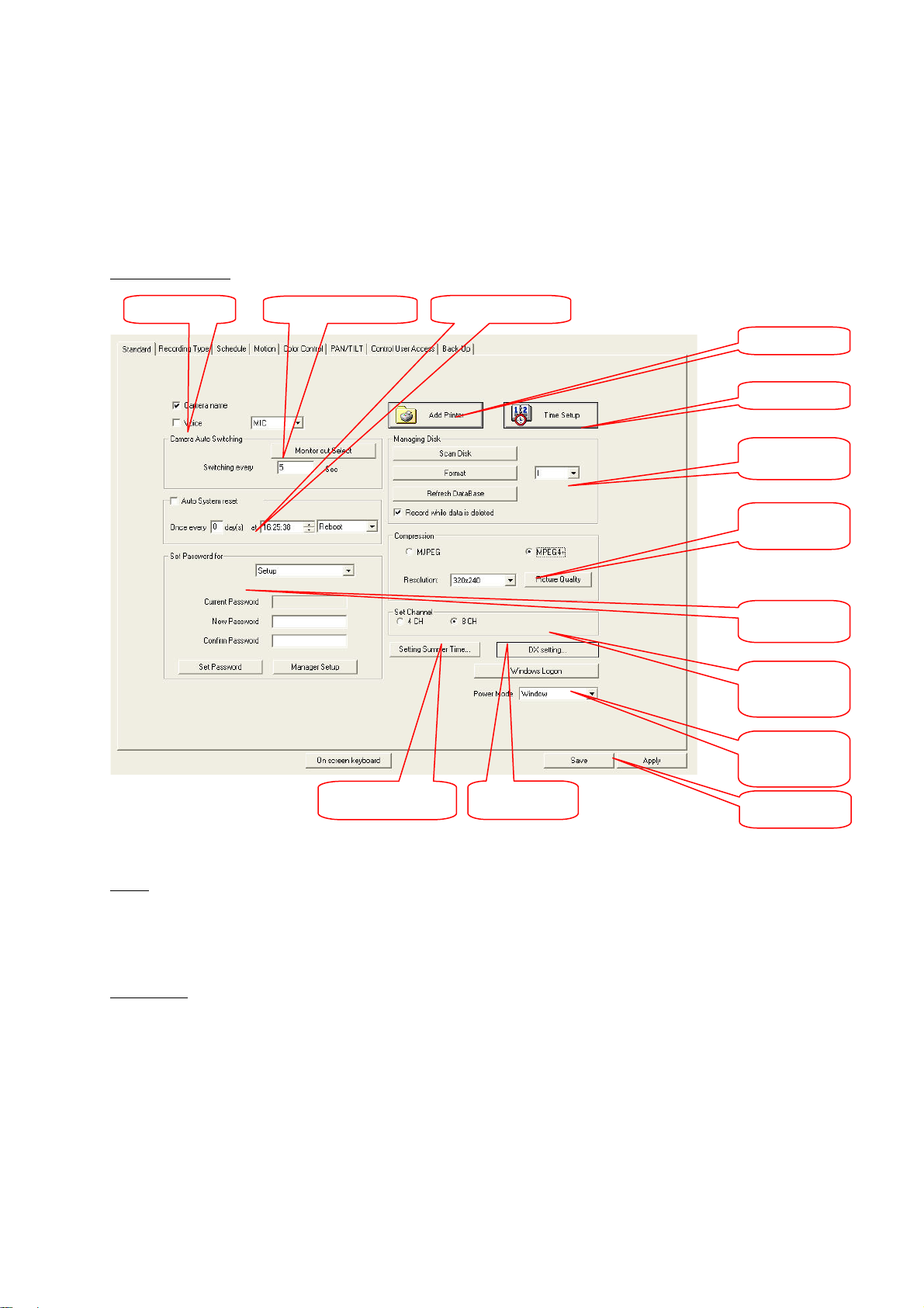
Programming the DigiProtect system
r
Via [Setup] in the live screen, you open the configuration menu of the digital surveillance system. You
can save your settings by clicking [Save]. Click [Apply] to save your settings and exit Setup. In Setup,
you can set the following functions:
Standard settings
Voice
Monitor out Select
Auto System reset
Add Printe
Time Setup
Disk Manager
Compression
settings
Password
Set Channel
Power Down
mode
Setting summer
DX-settings
Save/Apply
Voice
One channel is provided for recording audio data. The built-in sound card of the PC is used as input.
Click here to activate audio input (voice recording). Select between microphone (MIC) or line-in
(LINE).
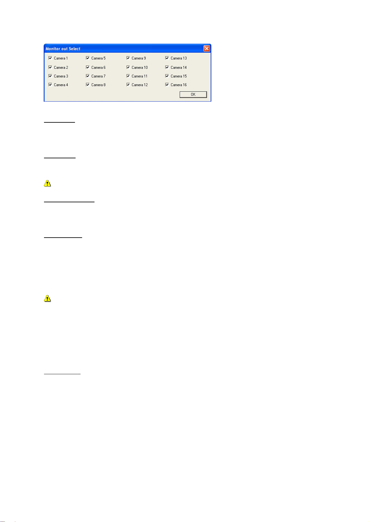
Monitor out
The video card of the digital surveillance system has a socket for connecting an external monitor
(Chinch connector next to the camera inputs). You can select channels for display on the external
monitor by clicking [Monitor out Select] (not Model TV8809, TV8810, TV8811). The display mode in
the surveillance system (single-picture, multi-channel display) is used for the external connection. In
the case of single-picture display, the channels can be shown in sequence. You can define the display
time (dwell time) of each channel by entering the time in seconds.
70
Page 14
Add Printer
Click to install a printer. You can connect a local or network printer to the surveillance system. You
install the printer via the Windows standard routine.
Time Setup
For setting the current system time
IMPORTANT: If you reset the clock, older video data may be overwritten.
Auto System reset
Reboots the recording system automatically. If necessary, you can merely switch off the system
(without rebooting).
Disk Manager
The disk manager includes functions for defining, checking and formatting a disk drive. From the
menu, you can select a drive letter for saving data (e.g., drive D). When all space is used up on this
drive, the system automatically goes to the next available drive letter.
[Scan Disk] checks the drive for errors. Click [Format] to delete all data from the drive via the Windows
formatting function.
IMPORTANT: If only one partition is available for saving data (e.g., C:\), the data is written to this
drive. In this case, the [Format] function must be carried out only once.
Click [Refresh DataBase] to check the structure of recorded data of the individual channels and
reorganise it automatically if necessary.
Enable [Recording while delete data] for continuous saving of recorded data. When the drive is full,
the oldest data is automatically overwritten. If this function is not enabled and no further memory is
available, an alarm tone sounds and a message appears, telling you to change the storage location.
Compression
Here you can set the compression type, the recording resolution and the recording quality.
Two compression methods are available for recorded video data: MJPEG (single-picture compression)
and MPEG4+ (picture-difference compression).
Three resolutions are provided for video pictures: 320 x 240, 720 x 240 or
720 x 480 pixels.
71
Page 15
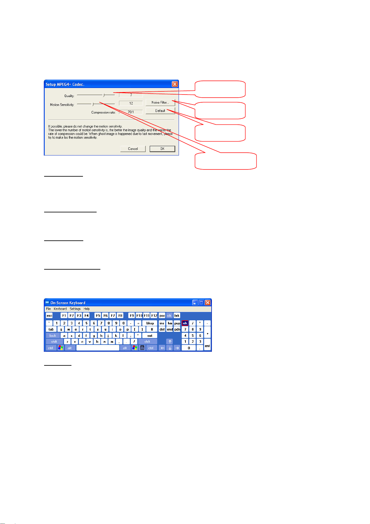
Click [Picture Quality] to select the compression rate. The higher the compression rate, the lower the
memory requirement, but the poorer the image quality.
For MPEG4+ compression, the sensitivity of the motion sensor must be set and the noise filter must
be set (see the following figure). The lower the sensitivity, the higher the image quality.
Quality
Noise filter
Default
Sensor sensitivity
Window logon
Enter a user name and password for a Windows logon. You need these for an automatic system start.
The data is automatically accepted by the operating system.
Power Down mode
When you switch of the digital surveillance system, the PC either returns to Windows or shuts down.
Camera name
Enable this option to display the name, number and status of each camera in the video picture.
On-screen keyboard
For entering camera names, passwords, etc., an on-screen keyboard is provided. You operate the
keyboard with the mouse. No external keyboard is required, which increases access protection.
Password
There are two ways of defining passwords for system access. With the first method, you can define
passwords for the setup, search, live screen access and switch-off levels.
72
Page 16
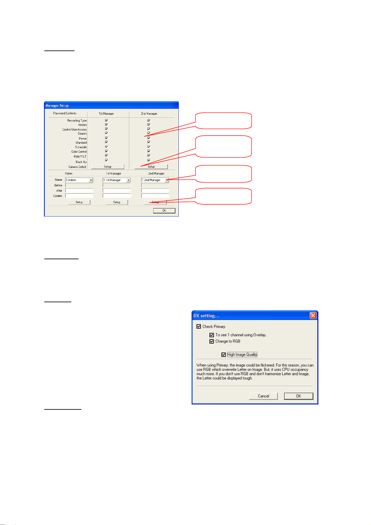
User setup
With the second method, you can define names and passwords for Level Administrator, 1st Manager
and 2nd Manager (14 each). User 1 of each level can access the user setup.
The administrator level has all access rights for the system. For each user, a password and access
rights to different levels can be defined. On these levels, users then have administrator rights. Before a
user has been installed, only the password has to be entered at [LOG IN].
Access rights
Camera Select
Name/password
Setup
If you click [Camera Select], you can also define the camera inputs visible to different users.
If you click [Setup] at the bottom of the window, the data you enter is accepted for the respective user.
Set Channel
The administrator can configure the video card used (4, 8 or 16) to the software of the digital
surveillance system. If channels are not used, they have to be deactivated under [Setup / Recording
Type] (no display and no recording – see next page).
DX-Setup
This menu is available in standard version only.
The DX-setup is used to adapt the VGA card to
the surveillance system. There are 2 display
modes available: 1. Primary mode, 2. Overlay
mode.
The software detects the best display mode
automatically. On display errors please activate
the primary mode. The RGB-function improves
the primary mode, but this consumes more CPU
power. In RGB mode you can set a better picture
quality (32 Bit).
Summer time
Here you can set the summer time. The DVR then is switching automatically between the summer and
winter time.
73
Page 17
Recording
yp
p
Channel no.
Alarm
Control
Pre/postrecording
Frame
rate
Record
Motion/Sen
sor Event
Video signal
Auto Camera
Search
Name
Event
setu
Recording
t
e
Alarm event
Video signal
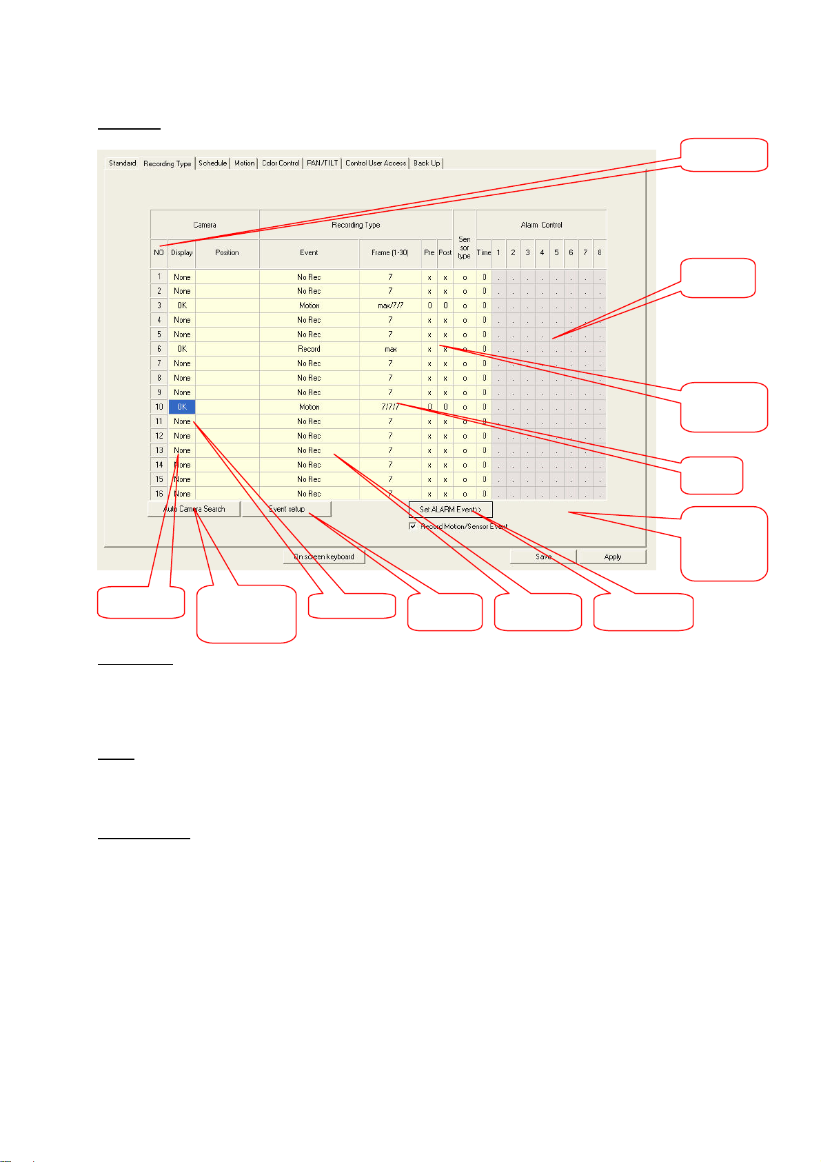
You can show or hide a connected camera on the live screen. Although an installed but hidden
camera is not shown in the live view, it is recorded with the corresponding setting. Left-click a channel
field to switch between options.
Name
You can give each camera input a name. This camera name is shown in the video picture and saved
with it. You can enter the name via a normal keyboard or the on-screen keyboard.
Recording type
The following recording types are available:
• Record: [continuous recording] The video data is recorded continuously.
• Motion: [motion-triggered recording] Recording is triggered by motion sensors
of the respective channel. You can configure the sensors under
[Setup / Motion]. They react to changes in the video picture (or parts
thereof).
• Sensor: [recording triggered by alarm sensor] Recording is controlled via max.
16 alarm inputs. The input connections are on a separate sensor
74
Page 18
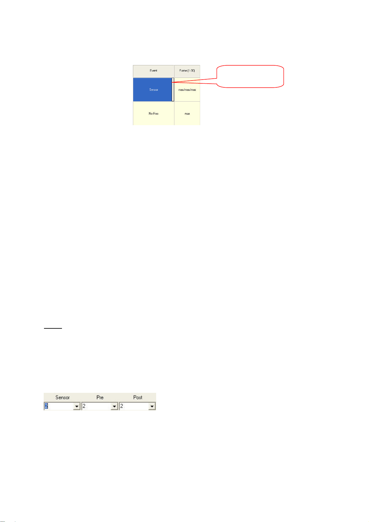
card, which has to be built in to the system. If you click the record
type button again, another button appears on the right.
Sensor selection button
Click this button to open a submenu. You can now choose the alarm
inputs to which the selected channel is to react.. Do this by enabling
the required alarm inputs (1–16).
• Schedule: [scheduled recording] Recording takes place according to a channel-
specific schedule. You can select a different recording type for every
hour. You define the schedule under [Setup / Schedule].
• Rec/Mot: [continuous recording / motion sensor] The video picture of the
channel is recorded continuously and for motion sensor events in this
channel.
• Rec/Sen: [continuous recording / alarm sensor] The video picture of the
channel is recorded continuously and on the triggering of the
respective alarm input.
• Mot/Sen: [motion/alarm sensor] The video picture of the channel is recorded if
either the motion sensor or the alarm sensor is triggered for this
channel.
• R/M/S: [record/motion/sensor] The video picture is recorded continuously and
if either the motion sensor or the alarm sensor is triggered for this
channel.
• No Record: No video data is recorded for this camera input.
Frame
Here you define the frame rate (number of pictures recorded per second) for the channels. In the PAL
standard, this is max. 25 frames per second. The frame rate can be variably defined, but the maximum
recording frame rate of the DigiProtect card used must not be exceeded (e.g., DigiProtect 25: max.
frame rate 25 frames per second for all channels).
Furthermore, for the motion sensor and alarm sensor recording types, the frame rates can be set
separately for pre- and post-event recording.
75
Page 19
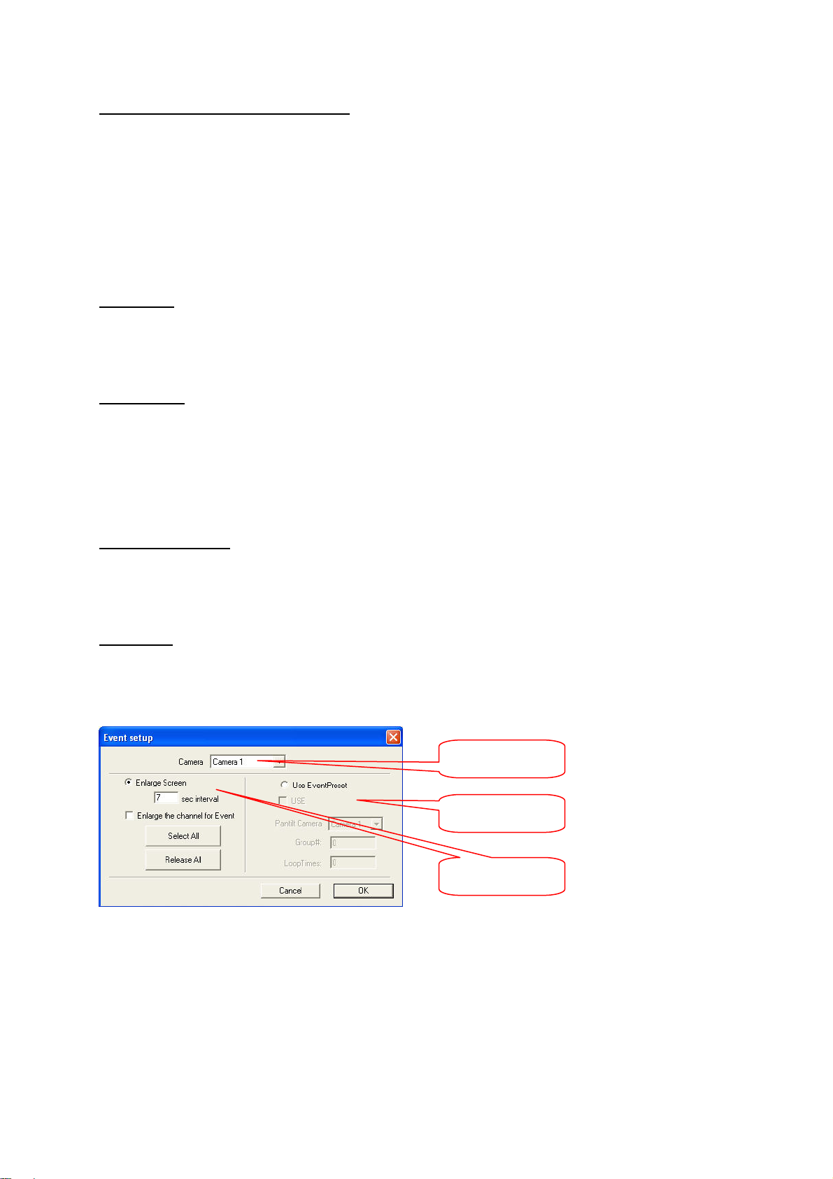
Pre- and post-event recording [Pre/Post]
The DigiProtect digital recording system has a so-called pre- and post-event recording feature. If
recording is triggered by a motion or alarm sensor, the system stores the video data of up to 20
minutes before and after the event. The pre-event recording data is buffered for the time specified and
retrieved if required (if an event occurs). The pre- and post-event recording times can be set at
anything between 1 second and 20 minutes.
Important: The pre-recording first functions following the expiry of the desired time after setting, since
otherwise the data is not written completely to the buffer.
Sensor type
Defines the switch type of the alarm inputs. It is either NO (normally open) or NC (normally closed). If
you select two or more alarm inputs for triggering recording under [Set ALARM Event], this switch
setting applies to all alarm inputs.
Alarm Control
The recording system can switch up to 8 alarm outputs for different events. The connections are on an
optional alarm card, which has to be built in to the system. Here you can define the alarm output to be
switched for an event. Possible events are motion detection, triggering of an alarm input, loss of video
signal and active recording status. The duration of the activation of the alarm output can be set
between 0 and 90 seconds. If this is set to [on], a short impulse is activated at the output.
Auto Camera Search
Click to search automatically for connected video sources. Sources found are activated for live display
and set to continuous recording.
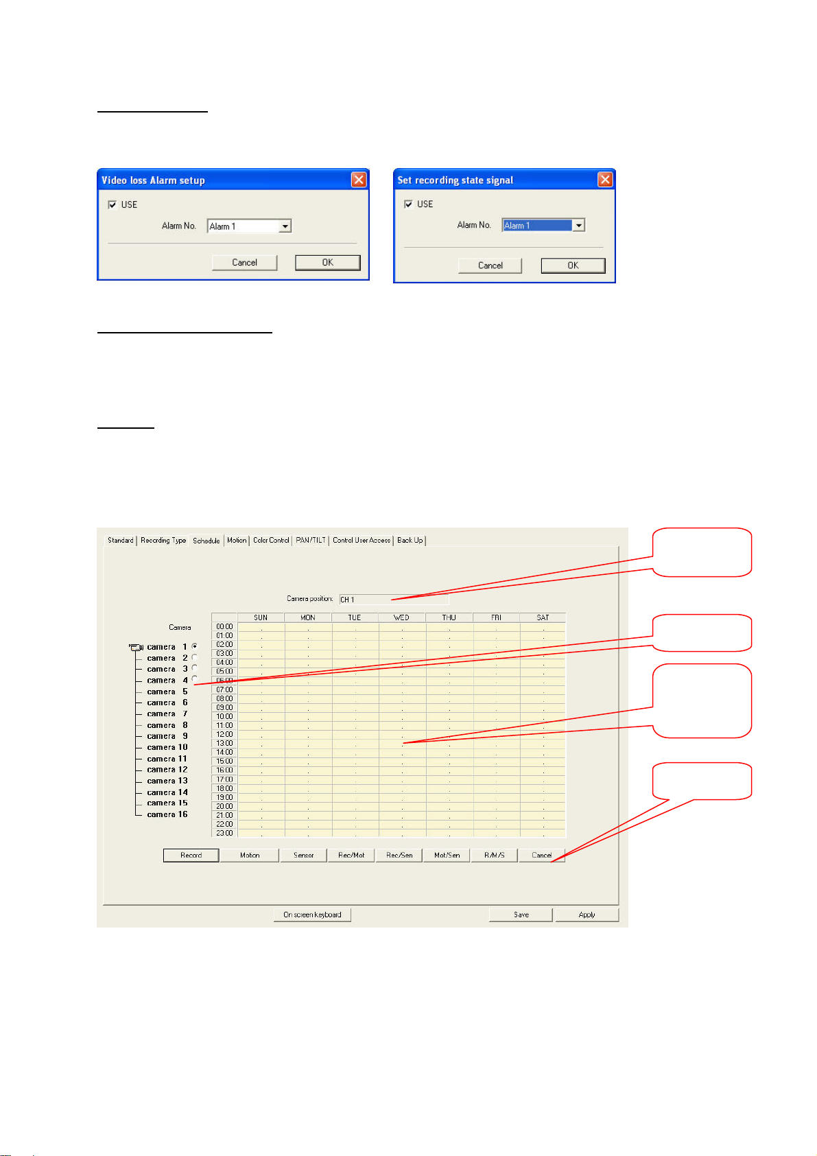
Event setup
Here you can activate a function that points to any event that occurs. Two functions are available:
The first function switches to full-screen display for a specific time if an event occurs.
The second function can control a dome camera if an event occurs.
Channel selector
Dome camera
control
Enlarge Screen
76
Page 20
Set ALARM Event
yp
Here you can forward a video signal loss and the recording state to an alarm output.
Record Motion/Sensor Event
If you enable this function, the event is registered on the playback screen under Function/Event
filter/Event memory/log.
Schedule
In the schedule, you can select a different recording type for each hour and camera. Mark a period
and click a recording type button in the lower part of the window. If you right-click the mark, you can
also switch between recording types.
Camera name
Camera no.
Marking and
activation of
recording type
Recording
t
e
77
Page 21
Motion
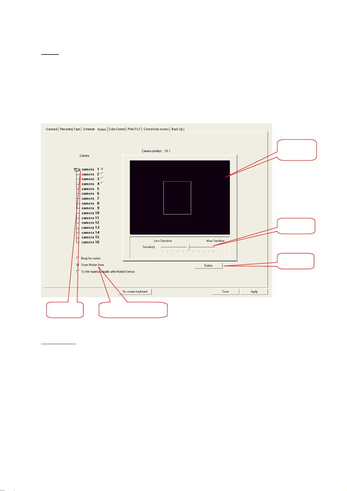
For motion-triggered recording, the motion sensors for the different cameras have to be configured.
Select a camera and mark the areas in the camera window to be monitored. With the Sensitivity slider,
you define how big the changes in the video picture have to be to trigger motion detection. Click
[Delete] to delete a marked area.
Enable [Beep for Motion] for an acoustic signal and [Show Motion Area] for an optical marking if
motion is detected. Select [To the maximum quality after Motion/Sensor] for recording at maximum
frame rate following an event.
Marking of
sensor area
Sensitivity
Delete/Clear
Camera no. Functions on movement
Color Control
Here you can set the brightness, saturation, contrast and hue of the channels. If you click [Setup
User’s Default], the settings for this channel are used. [Cancel User’s Default] resets all settings to the
default system values. [All Default Color] sets the values of all channels to the user settings. [Default
Color] sets the settings to the user definitions.
78
Page 22
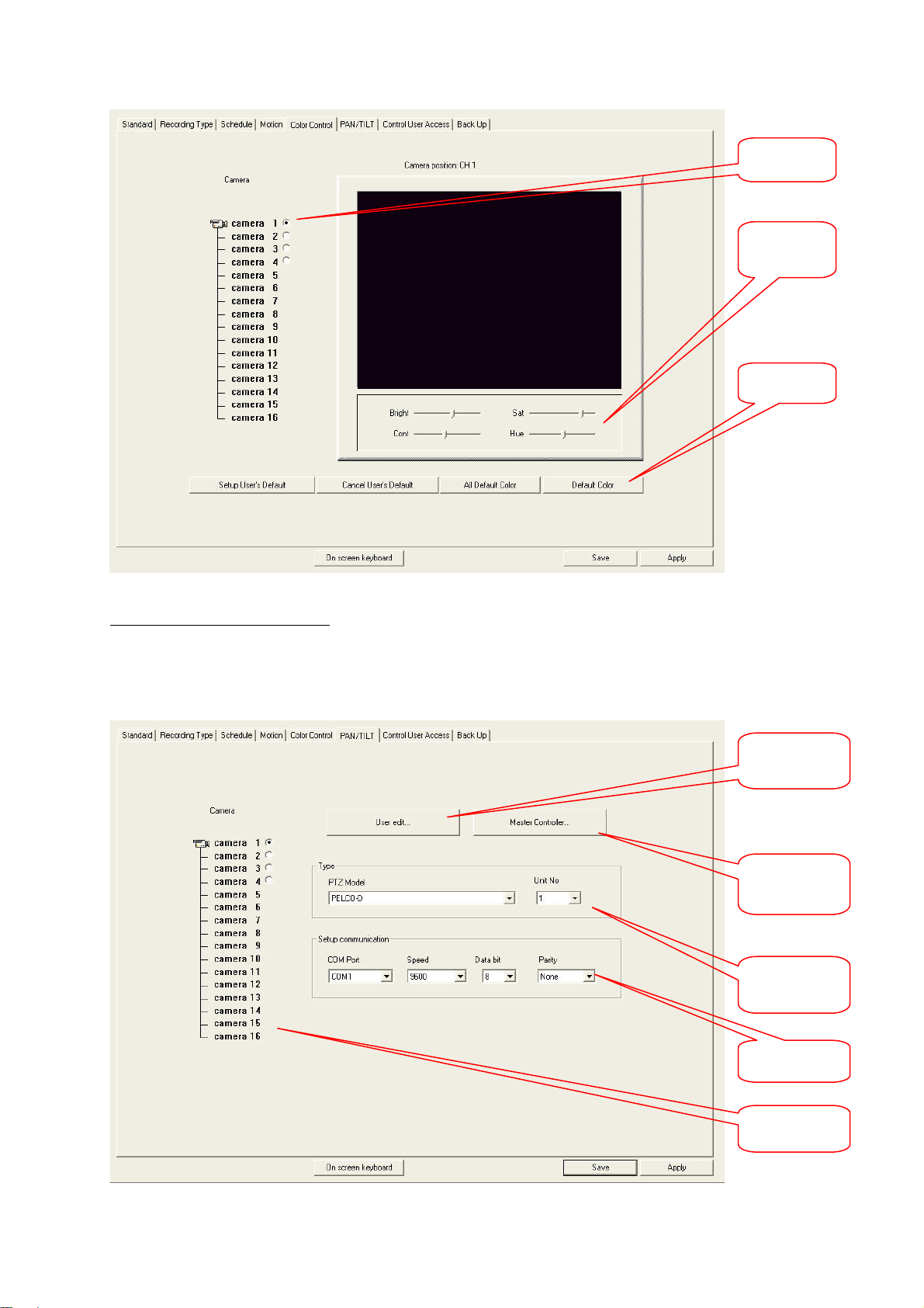
Channel
r
selector
Picture
settings
Save
PAN/TILT (dome camera) setup
With the digital surveillance system, you can control pan/tilt cameras (dome cameras). First select the
camera channel to which a dome camera is connected. Then select the connected model (protocol)
with the device number.
User edit
Master
Controller
Dome model
and device
numbe
Communi-
cation
Channel
selector
79
Page 23
You also have to set the communication parameters between the system and the dome camera
correctly (COM port no. on system, speed, data bits, parity).
User settings
If your dome camera is not on the model list, you can enter the specific control commands here (hex
code).
Master Controller
Here you can integrate a separate camera master controlled into the system. Select the model from
the list, set the communication parameters, and activate the device.
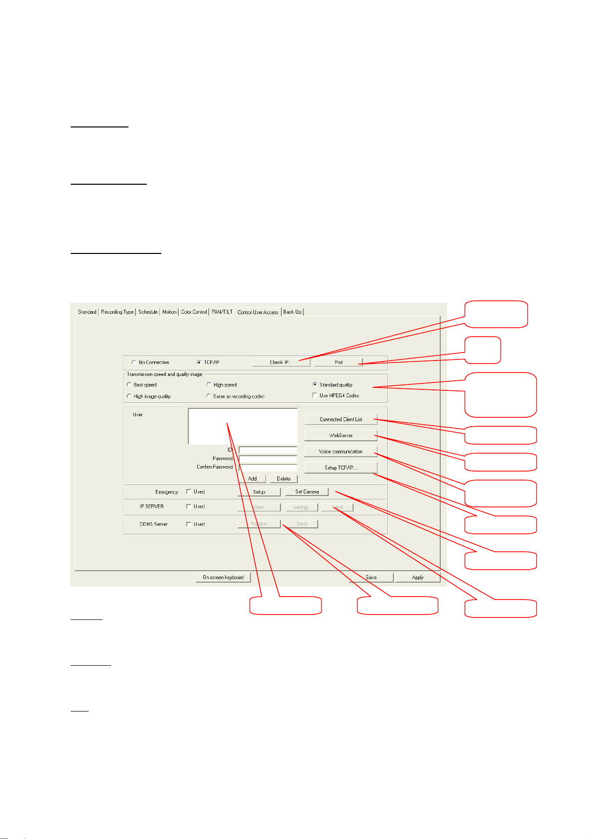
Control User Access
You can have remote access to the digital surveillance system via a network. The system then works
as a server. A user accessing this server is called a client.
Check IP
Port
Transmission
speed
Image quality
Client-List
Web-Server
Voice
communic.
Setup TCP/IP
Emergency
TCP/IP
DDNS-Server User
IP-Server
To enable remote access, click [TCP/IP].
Check IP
The server IP is defined either automatically or manually.
Port
Define the network port here. The default setting is Port 2000. The server and client port numbers
must be identical.
80
Page 24
Transmission speed and image quality
Select a quality or speed according to the connected network.
User
Here you can add or delete network users. To add a user, define the user ID and password, confirm
the password and click [Add]. You can remove a user with [Delete].
Connected Client List
Click to view all active connections.
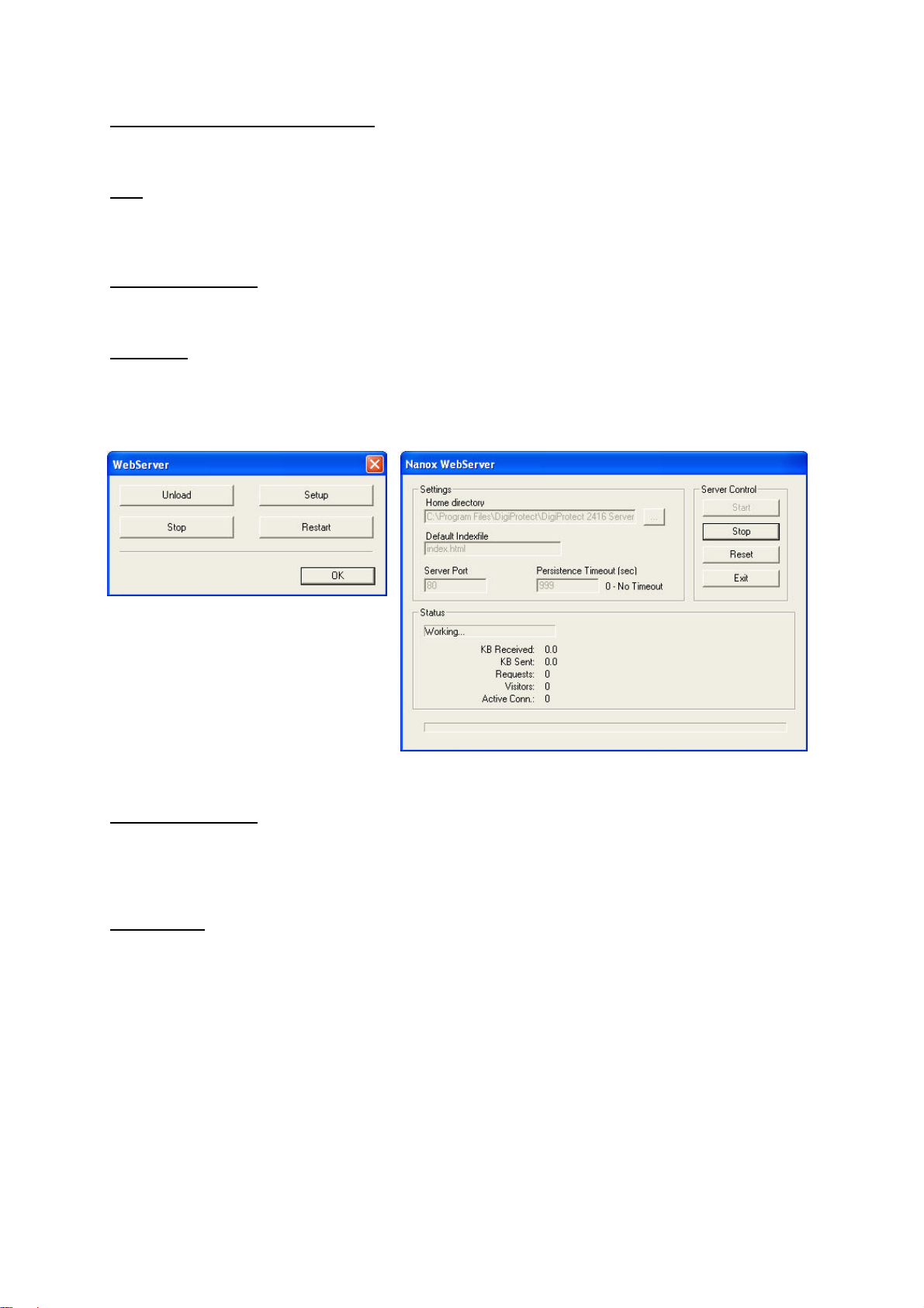
WebServer
The digital surveillance system has a built-in web server that allows access to the system via the
Internet Explorer. The user can access the system by entering the IP address in the address bar of the
Internet Explorer.
Under [Settings], you enter the setup of the web server. This is active following system installation. If
necessary, the port of the web server can be changed under [Server Port].
Voice communication
Voice communication is possible between server and client. Enable communication and select a
connected user. The microphone is connected to the line-in port of the PC. The voice recording
function and [Setup / Standard / Voice] must not be enabled.
Setup TCP/IP
Here you can make settings for the TCP/IP protocol. You can define this data automatically or
manually, depending on the network connection. For manual definition, enter the IP address, the
subnet mask, the gateway, and the DNS of the network adapter in the respective fields. If you use a
router, enter a local IP and user the router IP as gateway and DNS.
81
Page 25
Emergency Call
r
With this function, an emergency call can be made to a telephone number if an event such as an
alarm occurs. For this you need a voice modem integrated in the system. For an own emergency call
please overwrite the file „C:\Program files\DigiProtect\DigiProtect xxxx Server\TemC.wav“ (8kHz, 16
bit mono) with an own file.
DDNS server
Via the DDNS function, a constantly changing IP is made known via an address in the Internet
registered with DynDNS (e.g., via www.dyndns.org). Enable the DDNS server function, enter your
DDNS access data, and define the interval at which the IP is to be checked.
IP server
Via the IP server function, the IP can also be linked to any site name.
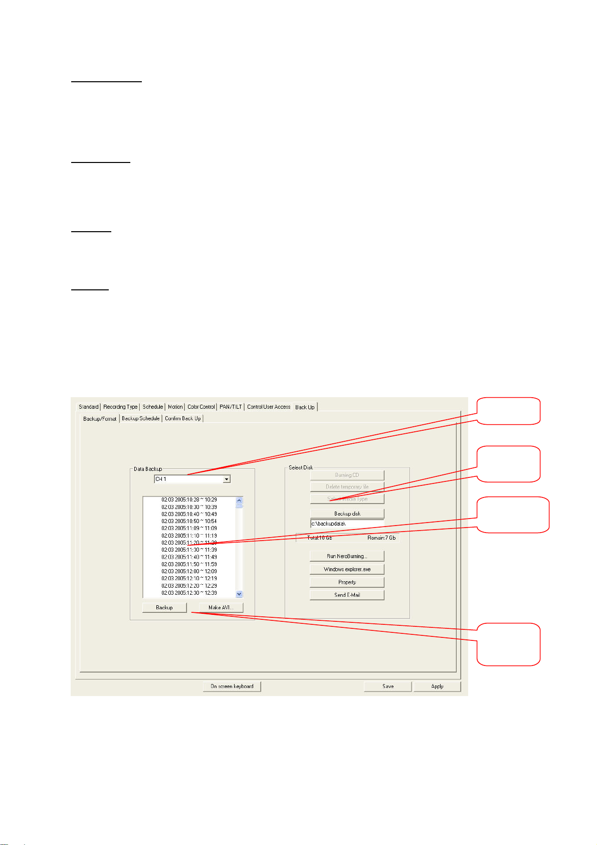
Back Up
Here you can define the making of backups. The data can either be backed up in database format or
as an AVI file. In database format, the data can only be edited on this system or with the special
software (Searcher) supplied. As an AVI file, the video data can be displayed with programs such as
the Windows Media Player.
First select the channel whose data you want to back up. In the window below, select a period. Click
[Backup] to save the data in database format. Click [Make AVI..] for AVI conversion.
Channel
selecto
Backup
folder
Period
selection
Backup /
Make AVI
82
Page 26
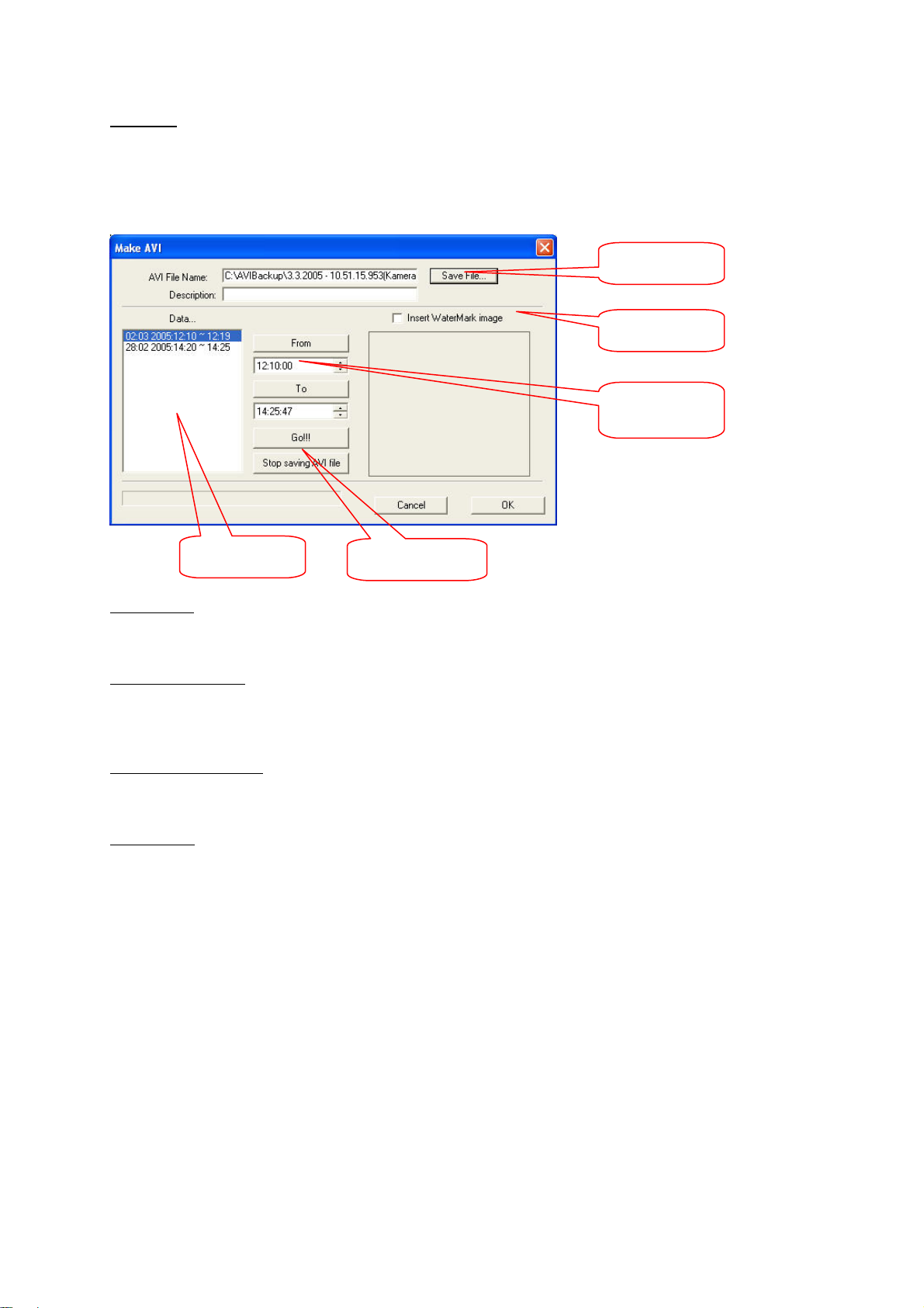
Make AVI
If you click [Make AVI..], the AVI converter opens. Select a period under [Data]. Click [Save File…] and
enter a file name. Confirm with [Save]. In the centre of the AVI converter, you can restrict the period
for which an AVI file is generated. Click [Insert WaterMark] to assign a digital watermark to each AVI
file. Click [Go!] to start the conversion process.
File name
Watermark
Period
Data selection
Start / Stop
Backup disk
Click to select the path for the backup data.
Run NeroBurning…
Click to start the Nero CD burn application automatically (if installed on your system). The data is then
backed up to an external storage medium.
Windows explorer.exe
Click to open the Windows Explorer for data management.
Send E-Mail
You can send a converted AVI file immediately as an e-mail. First create an AVI file. Then click [Send
E-Mail]. A password entry window opens.
83
Page 27
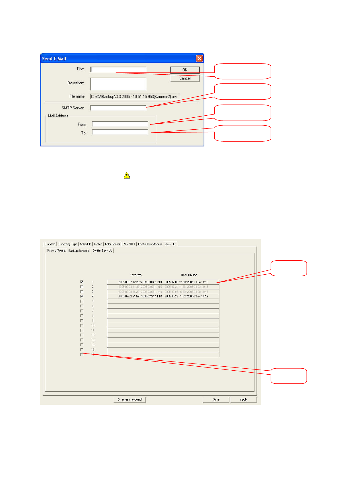
r
Title / Description
SMTP Server
Sender’s address
Recipient’s address
Enter a title and breif description of the short film scene. The file name of the last generated AVI file
appears automatically. On the next line, enter the SMTP server address of your e-mail provider (e.g.:
mail.gmx.net). Under [Mail Address], enter your own address (From) and the destination address (To).
Click [OK] to send the e-mail.
IMPORTANT: Make sure the recipient’s mailbox has sufficient
capacity.
Backup Schedule
Here you can define that a backup for a particular period is made at the specified time. First highlight a
channel and then select it by clicking [Channel]. Define the period you want to save under [Save time]
and the backup time under [Back Up Time].
Channel
selecto
Enable
84
Page 28
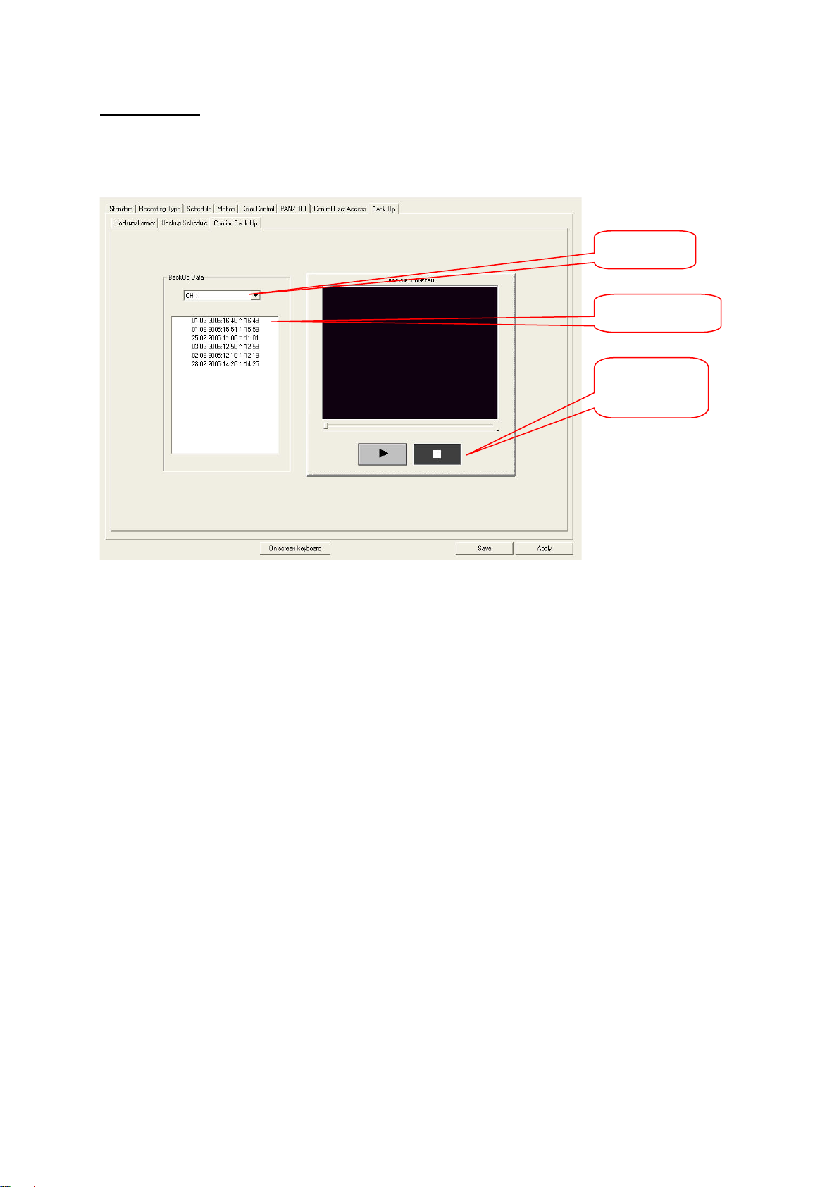
Confirm Backup
r
Here you can view backed-up data. On the left, select a channel and the backup section, and click the
playback or stop button on the right.
Channel
selecto
Backup section
Playback/Stop
85
Page 29
Operating the digital surveillance system
Controlling dome (PTZ) cameras
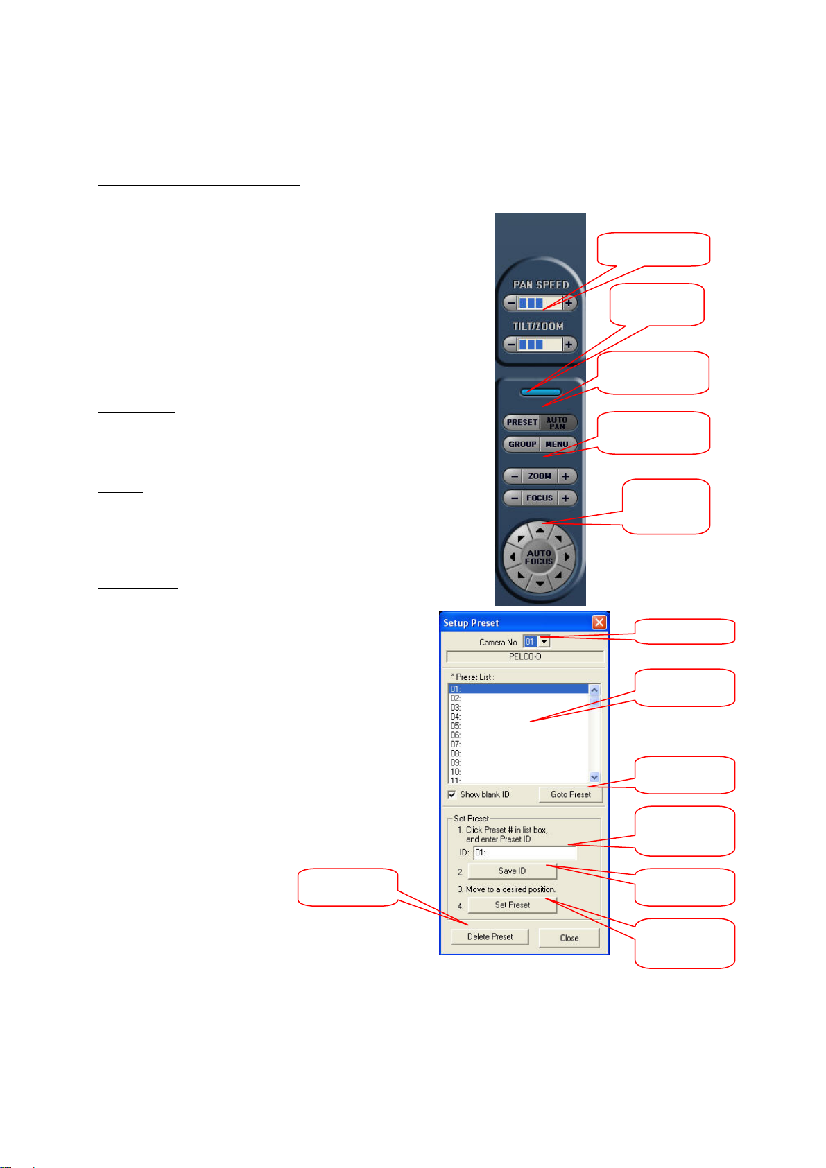
To open the dome control tab, click [PAN/TILT] in the live
screen.
With the digital surveillance system, you can control a large
number of PTZ (dome) cameras. You first have to configure
a connected PTZ camera on the [Setup/PAN/TILT] tab.
Speed
The pan and tilt speeds can be adjusted according to
requirements.
Zoom/Focus
You can zoom and focus the camera manually with the [+]
and [–] buttons.
Control
This contains the direction control buttons. At the centre is
an autofocus button (not active for all cameras).
Setup Preset
Under [Preset], you can save and retrieve
camera positions. Up to 64 preset positions
can be saved for each camera channel.
Select a number from the Preset list and name
this position under [ID]. Now move the camera
to the desired position and then click [Save
ID]. Remove a preset with [Delete Preset].
Delete Preset Save ID
Speed
Exit
Settings
Zoom/Focus
Control
Camera no.
Preset list
Go to preset
Name/ID
Set Preset
86
Page 30
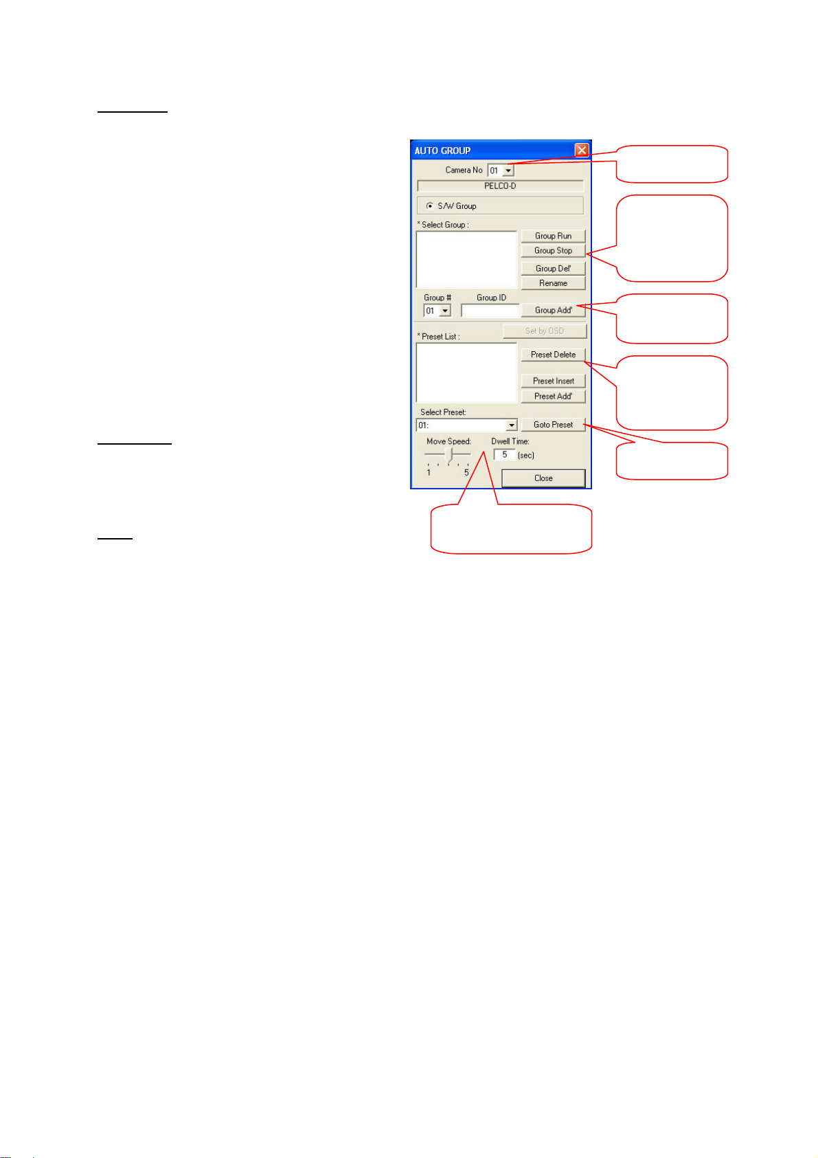
Auto Group
This figure shows the Auto Group window.
Here you can form a group of preset
positions. The positions of this group are
then automatically set by this camera at
specific successive time intervals.
Enter a group number and ID and click
[Group Add]. In the lower half, select a
preset and click [Preset Add]. Add all
desired positions to the group. Then click
[Group Run] to start automatic positioning.
At the bottom, you can set the movement
speed and the dwell time for each
position.
Setup menu
Here you can control various functions of
the PTZ camera. These functions cannot
be accessed for all camera models.
Close
Click this blue button to close camera control.
Camera no.
Group Run
Group Stop
Group Del
Rename
Group # / ID /
Add
Preset Delete
Preset Insert
Preset Add
Goto Preset
Movement speed / Dwell
time
87
Page 31
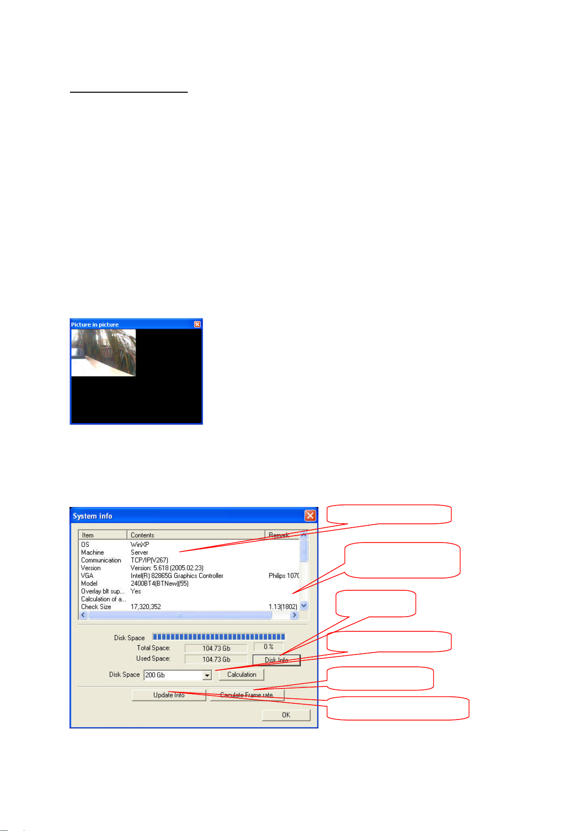
Subfunctions of live screen
Views
As mentioned above, the video section of the live screen can be divided into 4, 6, 7, 9, 10, 13 or 16
smaller screens. The channels can be swapped around on the screen. To move a channel, left-click it
and keep the left mouse button pressed. Drag the video picture to the desired position and drop it
there.
If you left-click a channel, you can change it to full-screen display. Click again to return to the original
view. A right-click enlarges the video area to fill the whole screen.
Other functions are available in the live screen. You access these functions by clicking [FUNCTION].
Recording Preview
The preview shows all currently recorded channels.
System Information (SYS-INFO)
Provides information on operating system, program version or system hardware. Other useful tools are
the recording calculator, drive info or the frame-rate calculator.
Hard- and software info
Probable recording space
free
Disk Info
Recording calculator
Calculate Frame rate
Update Info
88
Page 32
Recording calculator
With this calculator, the recording duration can be roughly calculated for a known memory capacity. All
recording, resolution and quality settings are taken into account. The upper window shows the
probable recording duration after the hard-disk size is selected.
Disk Info
Click this button to display information on the total space, used space and free space of the current
recording disk in a window.
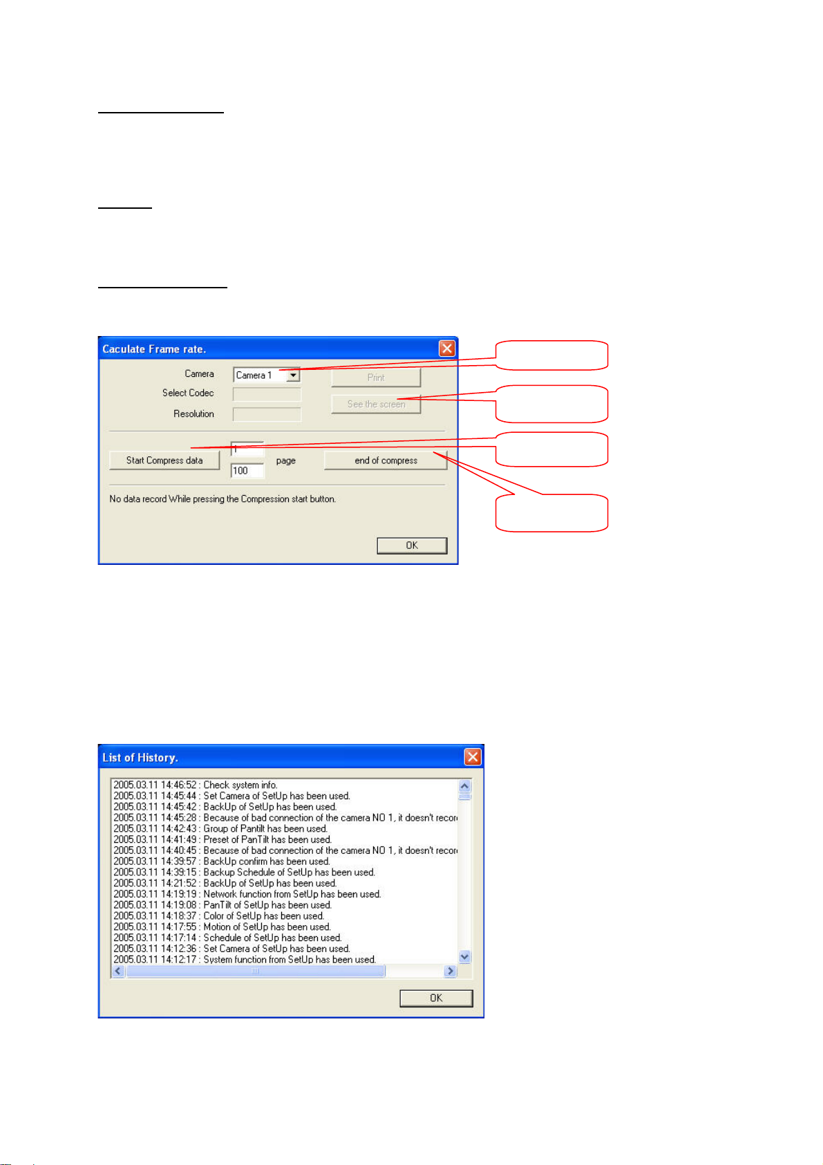
Calculate Frame rate
This program calculates the compression rate and single-frame size of individual channel s.
Channel selector
Result
Start
Stop
First select a camera or channel. Click [Start Compress data] to start the calculation. When the
calculation is complete, you can display the picture size and compression with the different Codec
variants on the screen. To do this, press [See the screen]. The number of pictures used for the
calculation can be changed on the right of the [Start Compress data] button.
Update History
The history log contains the functions used by the system.
89
Page 33
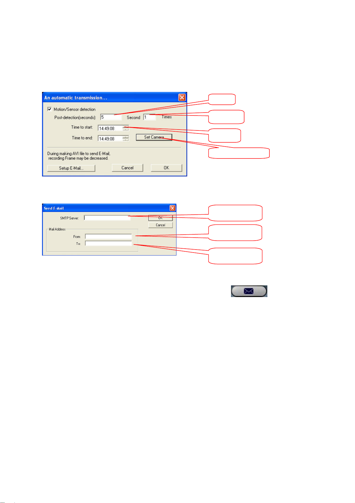
Sending an automatic e-mail
This function automatically sends an e-mail in the event of motion detection or an alarm. The content
of the e-mail is an AVI sequence of any length. The length is defined by the entry under [Postdetection] in seconds, and the frequency by the entry in the field behind. Enter a start and end time to
restrict the period of this function (e.g., 22:00 – 07:00).
Length
Frequency
Period
Camera selection
Click [Setup E-Mail] to make settings for the send process. Enter the address of your mail server, your
own address and the destination address.
SMTP server
Sender’s address
Recipient’s
address
Message function
This function permits the sending of network messages to
connected network users. Enable a message and select a
connected user. Click [Send] to send the message.
90
Page 34
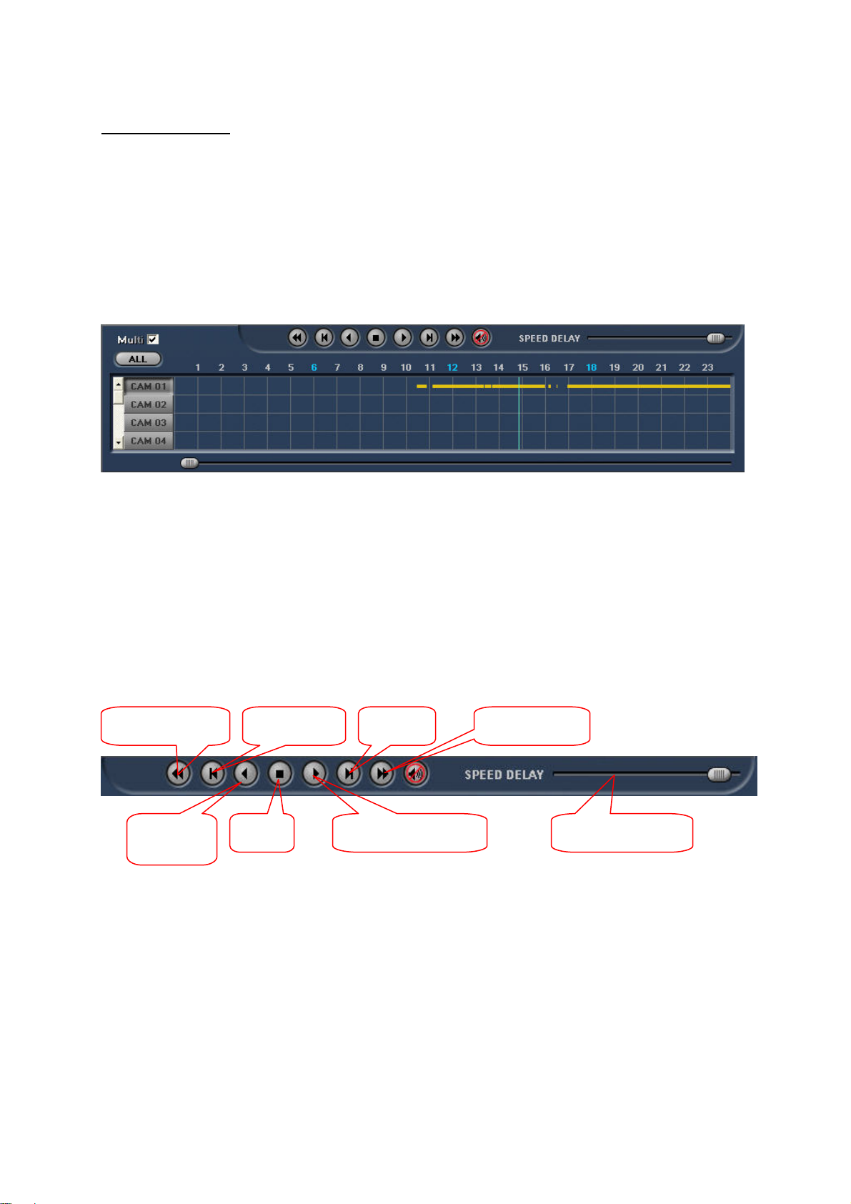
Controlling playback
y
y
Search bar
The search bar displays clearly all recorded video data as coloured bars for each channel. Switches
are provided on the left for displaying the desired channel in the video area. Four channels are shown
at a time in the search bar. With the vertical scroll bar on the left, you can select other channels. If you
check [Multi], the division of pictures is adapted automatically. If you click [All], all available channels
are displayed with a corresponding picture division in the video area.
To select video data, left-click a time in the search bar. The currently selected time is marked by a
vertical line. There are 3 different time divisions available in the search bar: 24 hours, half-hour and
minute. You can switch between the time divisions by clicking the time bar label. With the horizontal
slider at the bottom of the screen, you can also adjust the search time.
Playback bar
These functions simplify playback of recorded video data. You can play back data continuously or
frame by frame. You can also play back the video pictures forwards or backwards at different speeds.
Rewind frame
b
frame
Forward
frame b
Fast forward Fast rewind
Reverse
playback
Forward playback Speed control Stop
Click the loudspeaker button to switch off any recorded audio data.
91
Page 35
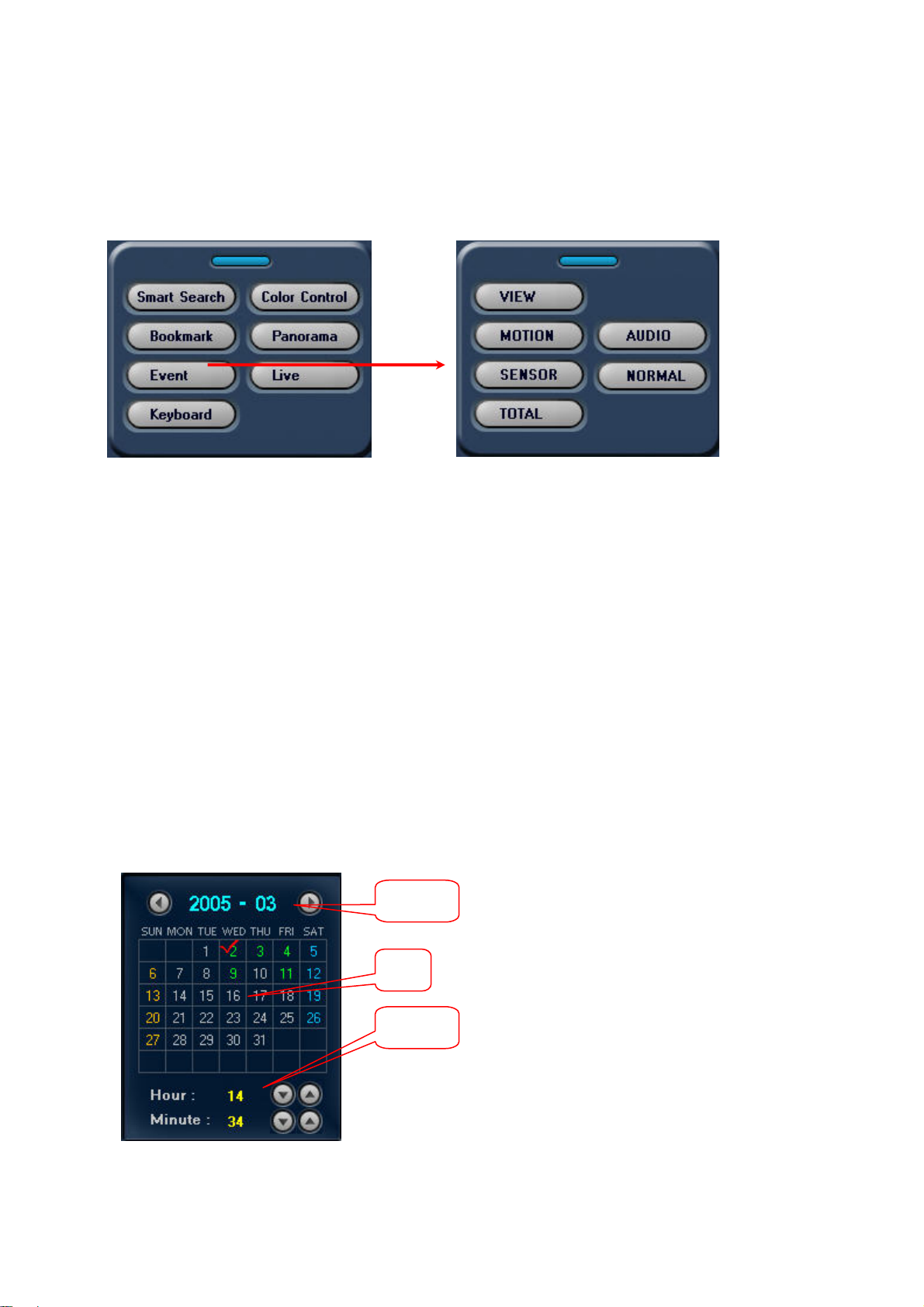
Event filters
These functions enable you to search recorded video data for different event types. First click
[Function] and then [Event].
The event memory (History) logs all events (date, time, camera number, event type). Click a line in the
event memory (History). If you click [Search Area], the vertical line in the search bar jumps to this
event and displays the respective video image. Click [Release all] to clear the event memory, or click
[OK] to close it.
The event filter enables you to search for the following:
- Motion events (pink) via [MOTION]
- Alarm events (blue) via [SENSOR]
- Voice recordings via [AUDIO]
- All events via [All]
- Normal display (yellow) via [NORMAL]
The different events are displayed in corresponding colours in the search bar.
Click the blue button at the top of the event filter to close it.
Date/time search
You can go directly to a time in the search bar. In the calendar, first select the year, month and date.
Month
You can select the hour and minute with the
up/down keys. The vertical line in the search
bar automatically jumps to the set time.
Date
Time
92
Page 36
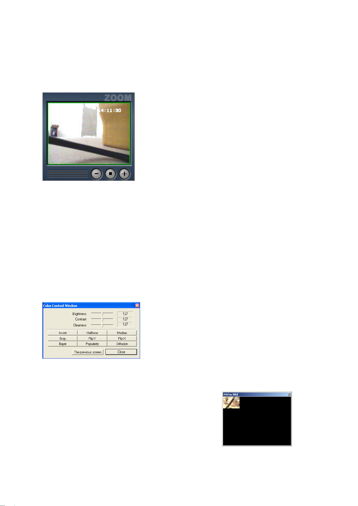
Zoom function
Use the zoom function to enlarge the recorded video picture. First select a video channel by leftclicking the video area. You can now change the zoom area in the zoom window with the [+] and [–]
buttons. The enlarged picture is displayed in the video area. You can drag the zoom area by pressing
and holding down the left mouse button.
Click the centre button to return the video picture to its original state.
Views
As described earlier, the division of the video area adapts automatically to the number of channels
selected in the search bar (1, 4, 9, 16). If you left-click a video picture in the video area, it changes to
single-picture display. If you right-click a video picture, the video area is enlarged to fill the screen;
right-click again to return to normal.
Colour setup
Select a channel for single-picture display. Click [FUNCTION] and then [Color Control]. You can now
select between different colour and picture display options.
Click on the previous screen to recover the default values.
Live view
Click [Live] to show all active channels.
93
Page 37
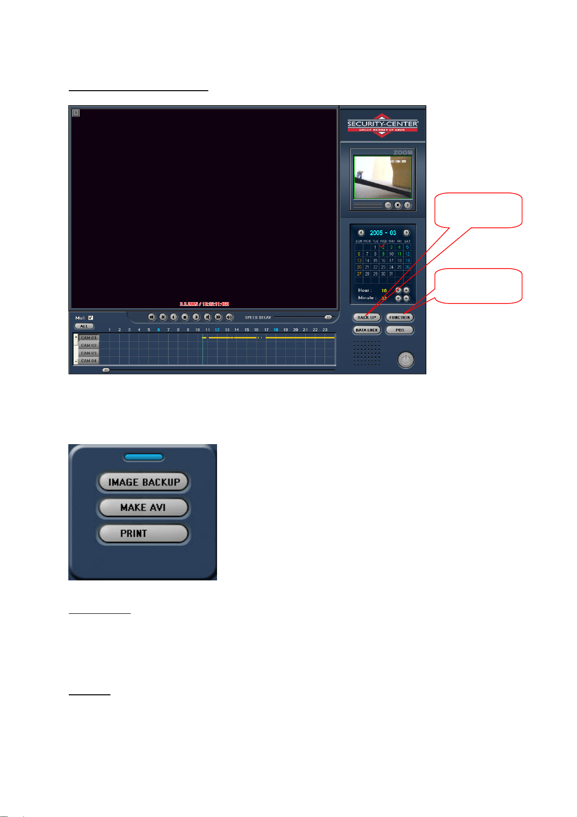
Subfunctions of playback screen
Data archiving
(backup)
Search functions
(functions)
Back Up
Click [Back Up] to use the data backup function.
Image Backup
With this function, you can save individual pictures as BMP, JPEG or YUV files. Click this button and
select the storage location. Enter a file name and type. Click [Backup] to save the picture.
Make AVI
On the playback screen, you can generate AVI sequences for data processing. The difference from
generating AVI files via [Setup / Backup] is that here you define only the start time in the video
sequence, and you end conversion with [Stop saving AVI file], or else it stops when no more video
data is available.
94
Page 38
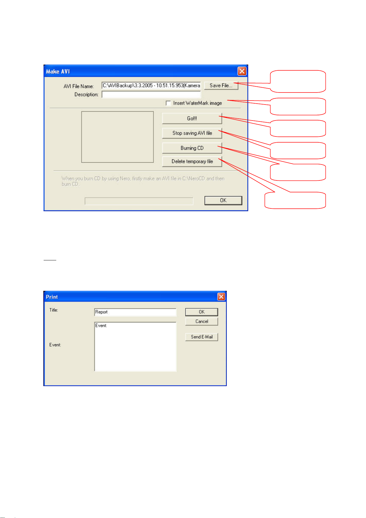
In the video area, click a channel to go into single-picture mode and mark a start time in the search
bar. Click [Backup / Make AVI] to open the AVI converter of the playback screen.
Define file name
Watermark
Start
Stop
CD burner
Delete temporary file
Click [Save File...]. The [Save As] dialog box opens. You can accept the suggested file name for the
video sequence by clicking [Save]. You can insert a description and a watermark.
Click [Start] to start conversion. Click [Stop making AVI file] to stop at any time.
Here you can print images from video recordings or send them by e-mail. You can start [Backup /
Print] from any video view (e.g. 4-screen view). You can enter a title and comment for the image.
Click [OK] to print the image on a system printer. Click [Send E-Mail] to send the image to an e-mail
address. Enter the SMTP server, your e-mail address and a destination address in the respective
fields. Close the dialog box with [OK].
95
Page 39
Search functions
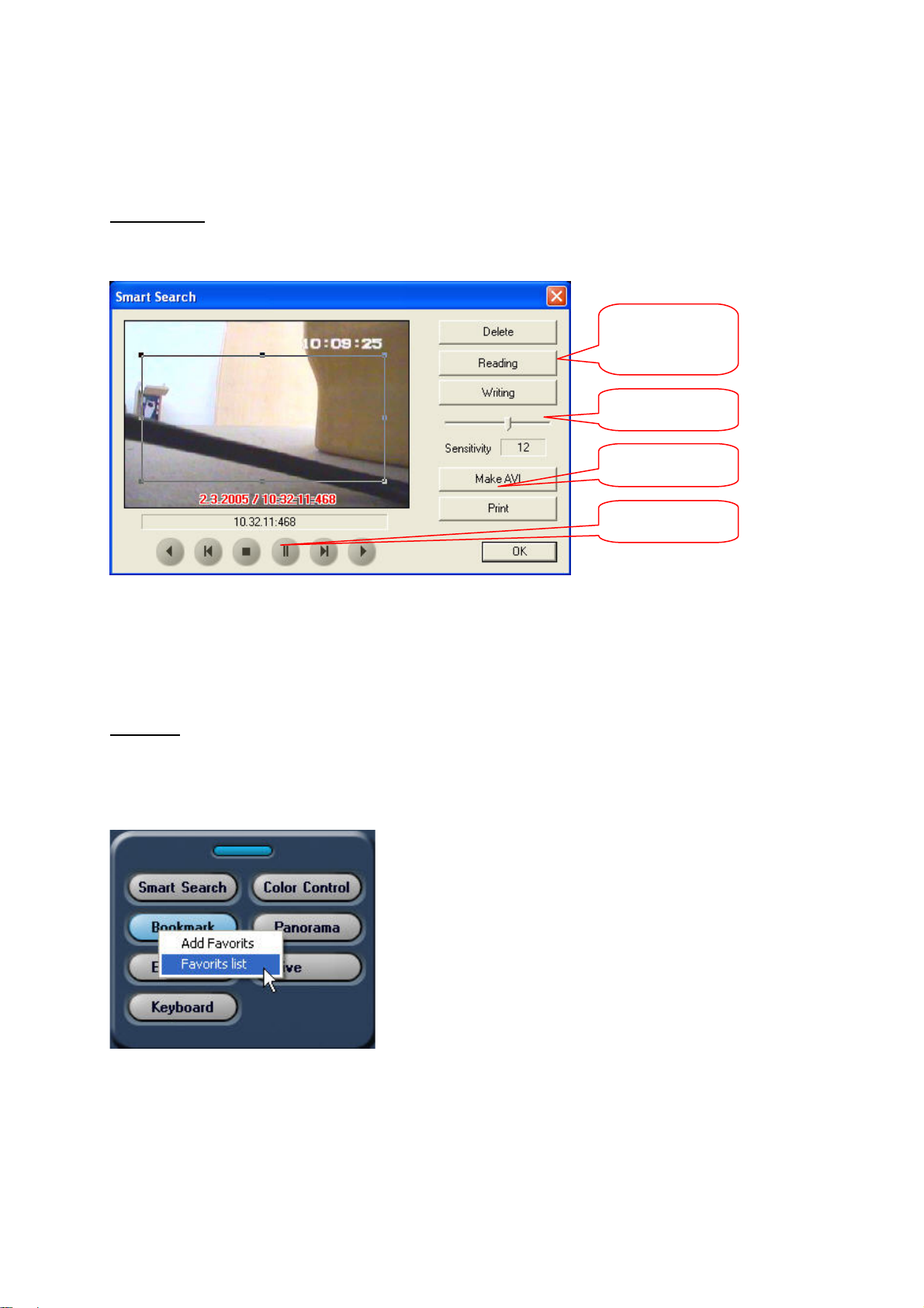
Smart Search
Use this function to search for changes in individual areas. In the search bar, mark the start time for
the search. Open the Smart Search dialog box via [FUNCTION] and [Smart Search].
Search area
Read/Write/Delete
Sensitivity
AVI / Print
Control keys
Mark one or more search areas in the video picture and define the sensitivity. The higher the
sensitivity, the smaller the changes that are registered. Click [Make AVI] to generate a video sequence
of the pictures in which the image has changed. Only marked areas are taken into consideration. Use
the control keys to play forwards or backwards continuously or just to the next scene. Click [Print] to
print individual pictures.
Bookmark
Bookmarks help you to find specific video sections in the recorded data. Go to the desired time in the
search bar. Click [FUNCTION] and then [Bookmark]. Buttons appear for adding favorites and
displaying a favorites list. Click [Add Favorites], enter a name and confirm with [OK].
Click [Favorites list], select a favorite and click [Go] to access the saved bookmark.
96
Page 40
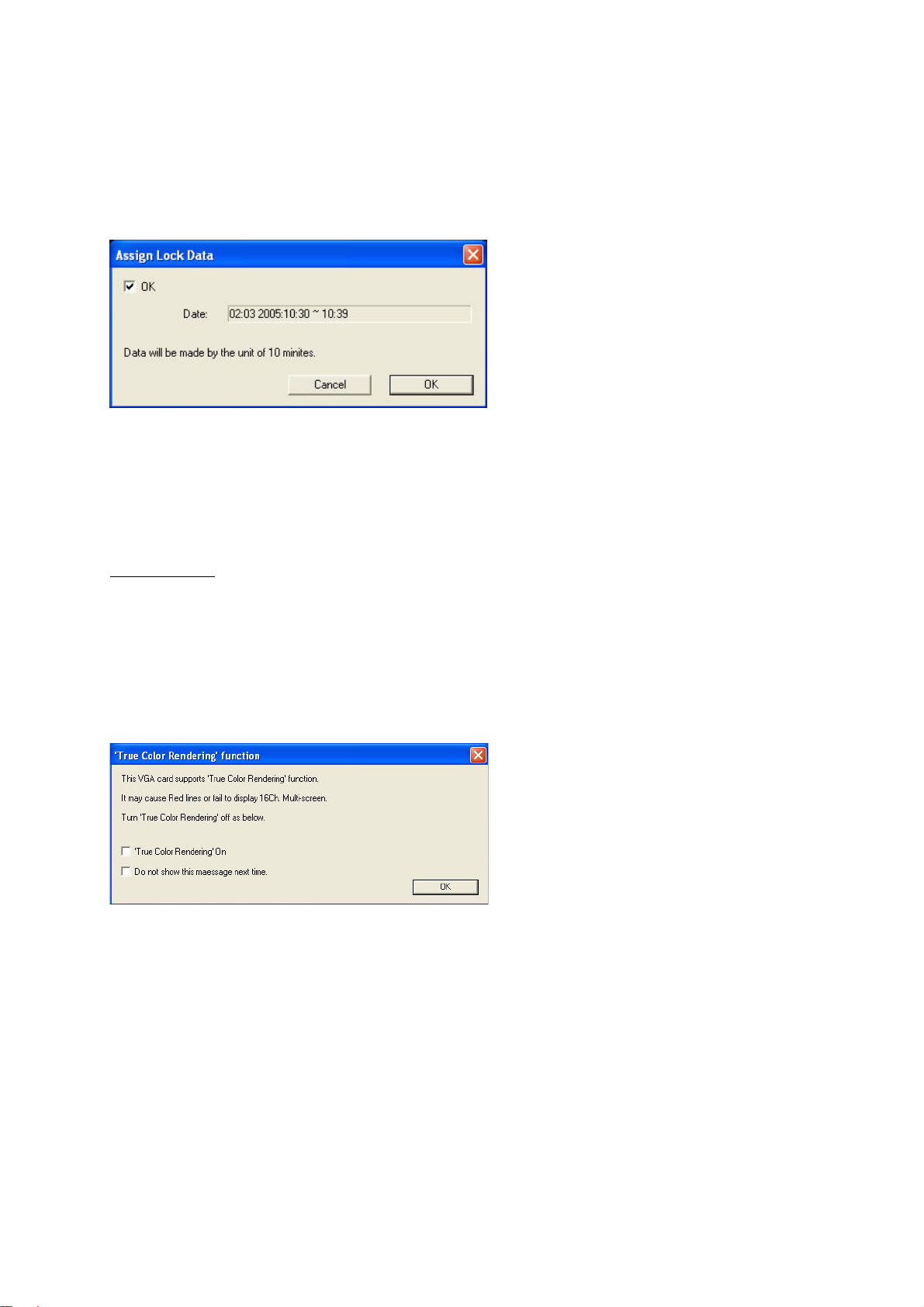
Data Lock
Use this function in the playback screen to protect data from overwriting. Click a time in the search bar
and then click [Data Lock]. If you set the check mark and confirm with [OK], this 10-minute section is
locked and marked light yellow in the search bar.
Network connection
To connect the digital surveillance system to a network or the Internet, you need a physical connection
via the LAN adapter or a modem.
Client Software
The Client software is used for remote monitoring of the server system via TCP/IP or modem. It
provides the same scope of functions for analysing recorded data as the server software. The client
software is on the CD supplied and must first be installed. Select the [DigiProtect Client] directory and
run “setup.exe”. Follow the instructions on the screen and complete the installation correctly.
Start the client software by double-clicking the desktop icon. You are asked to disable the “True Color
Rendering” function of the graphic card (no check mark set). Confirm with [OK].
The client software user interface and the connection dialog now open. You can choose between
modem, TCP/IP or IP server connection. First enter a name for the connection.
For a LAN (Local Area Network) connection, select [TCP/IP] and specify the IP address of the
destination server. For a server logon, you have to enter [ID] and [Password] as registered in the
DigiProtect server under [Setup / Network / User]. Click [Port] to change the communication port
(default: 2000). The port must be identical for the server and the client. You can edit a connection on
the list with [Insert], [Delete] and [replace].
Now click [Connect] to start communication with the server.
97
Page 41
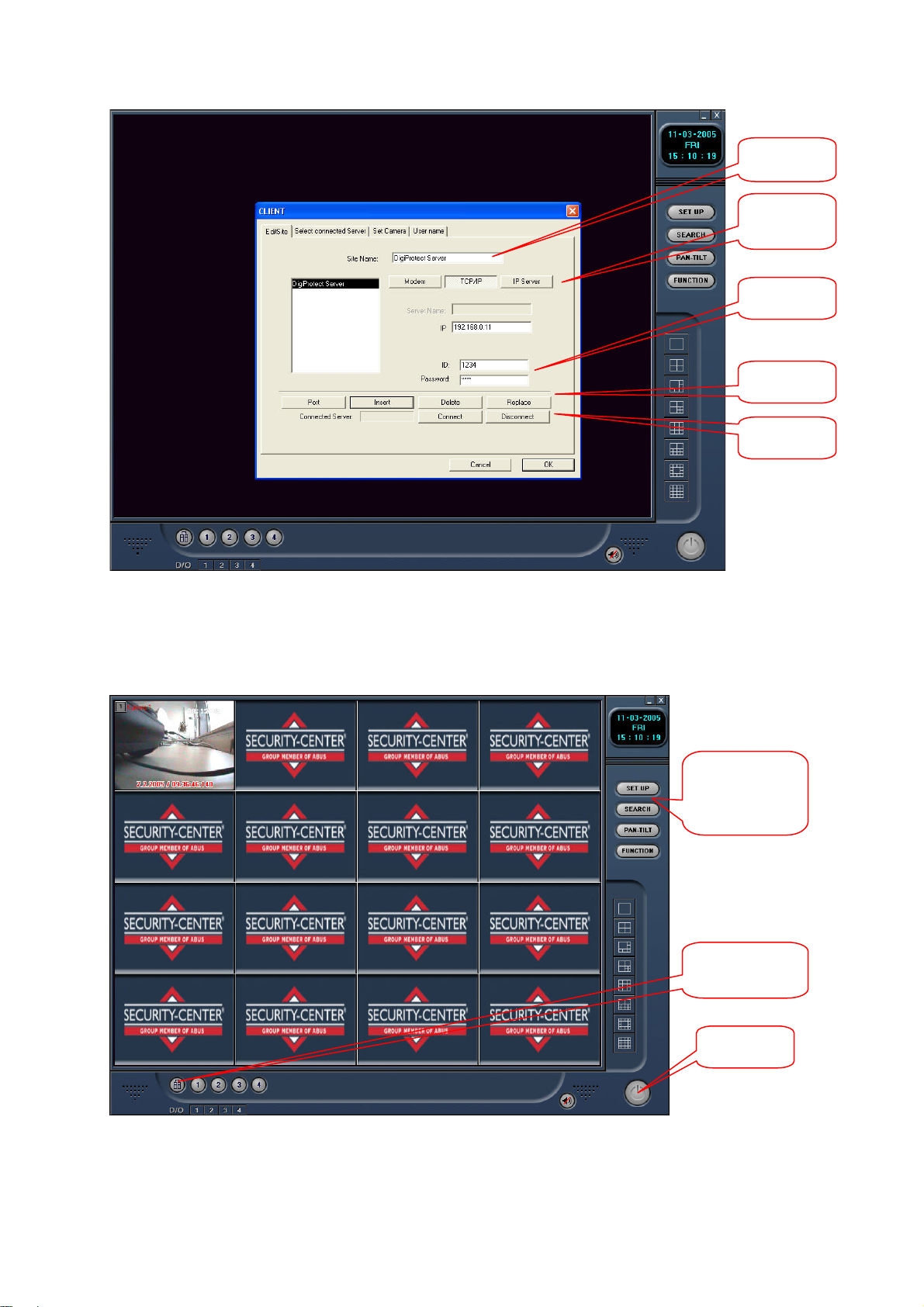
Server
name
Connection
type
ID /
Password
Edit
Connect
Now click [Connect] and [OK] to start communication with the server or display pictures. For the
transmitted data, you now have comprehensive search, analysis and control functions as in the server
software.
Setup / Playback
/ Dome Control /
Functions
Connection
setup
Exit
98
Page 42
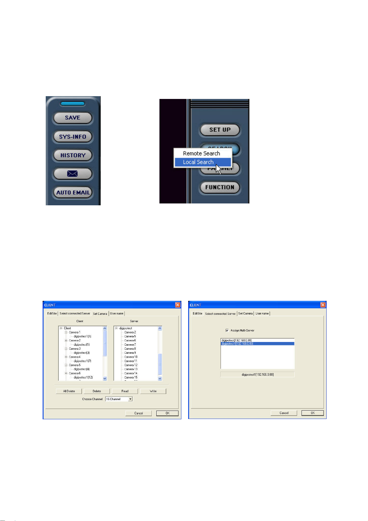
Direct recording
An additional function for saving data on a client system is direct recording. You can save the data
locally on the storage drive of the client PC by clicking [FUNCTION] and [Save].
You can access this data by clicking [Local Search]. Click [Remote Search] to access the data
recorded on the server.
Multi-server connections
With the DigiProtect Client software, you can access several servers simultaneously. Up to 16
cameras at 16 locations can be displayed simultaneously. First, connect to the different servers. The
[Select connected Server] tab lists all connected servers. Enable [Assign Multiserver]. Click [Set
Camera]. With the mouse, drag a camera from the list on the right (Server) to the list on the left
(Client). You can also save or load channel combinations. Click [OK] to open the video view.
99
Page 43
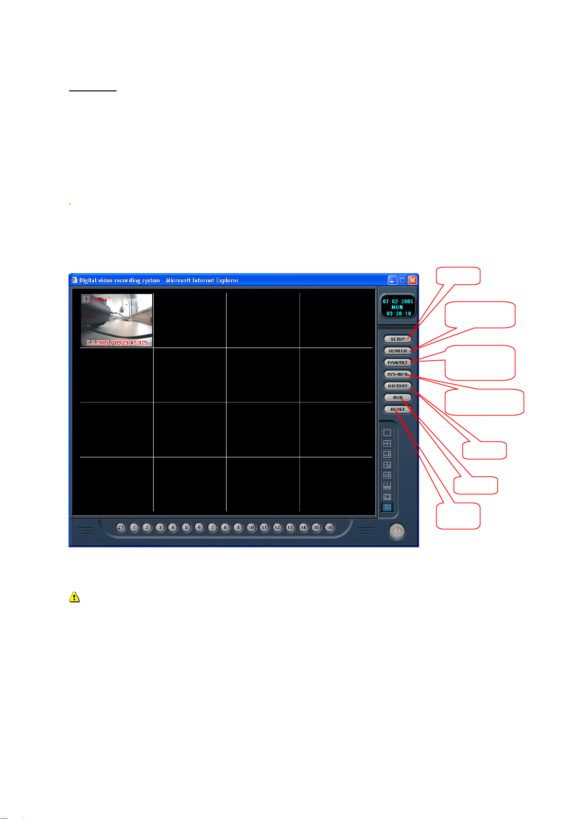
Web Client
The DigiProtect digital surveillance system integrates a so-called web-server. This provides data to the
connected network via the HTTP protocol. This enables you to access the DigiProtect server via the
Internet Explorer via the connected network. The web-server is automatically loaded when the server
starts.
Open the Internet Explorer of a PC connected to the network or the Internet. Enter the IP address or
the address registered via DynDNS in the address line and confirm your input. The web-server of the
destination server opens and you are asked to confirm the loading of a plug-in.
IMPORTANT: Your Windows setup may have various functions that prevent loading a plug-in
(Firewall, Popup-Blocker, Download ActiveX control elements not permitted).
Enter the data of a user installed in the server program under [Setup / Network] to receive access to
the web interface. The web interface opens.
Setup
Playback/Sear
ch
Dome control
Playback/Search
History
OVR
Reset
IMPORTANT: If the selected user has access to all functions of the server program, he/she can
make all server settings via this web interface. You should therefore protect the setup level from
unauthorised access by using passwords.
100
Page 44
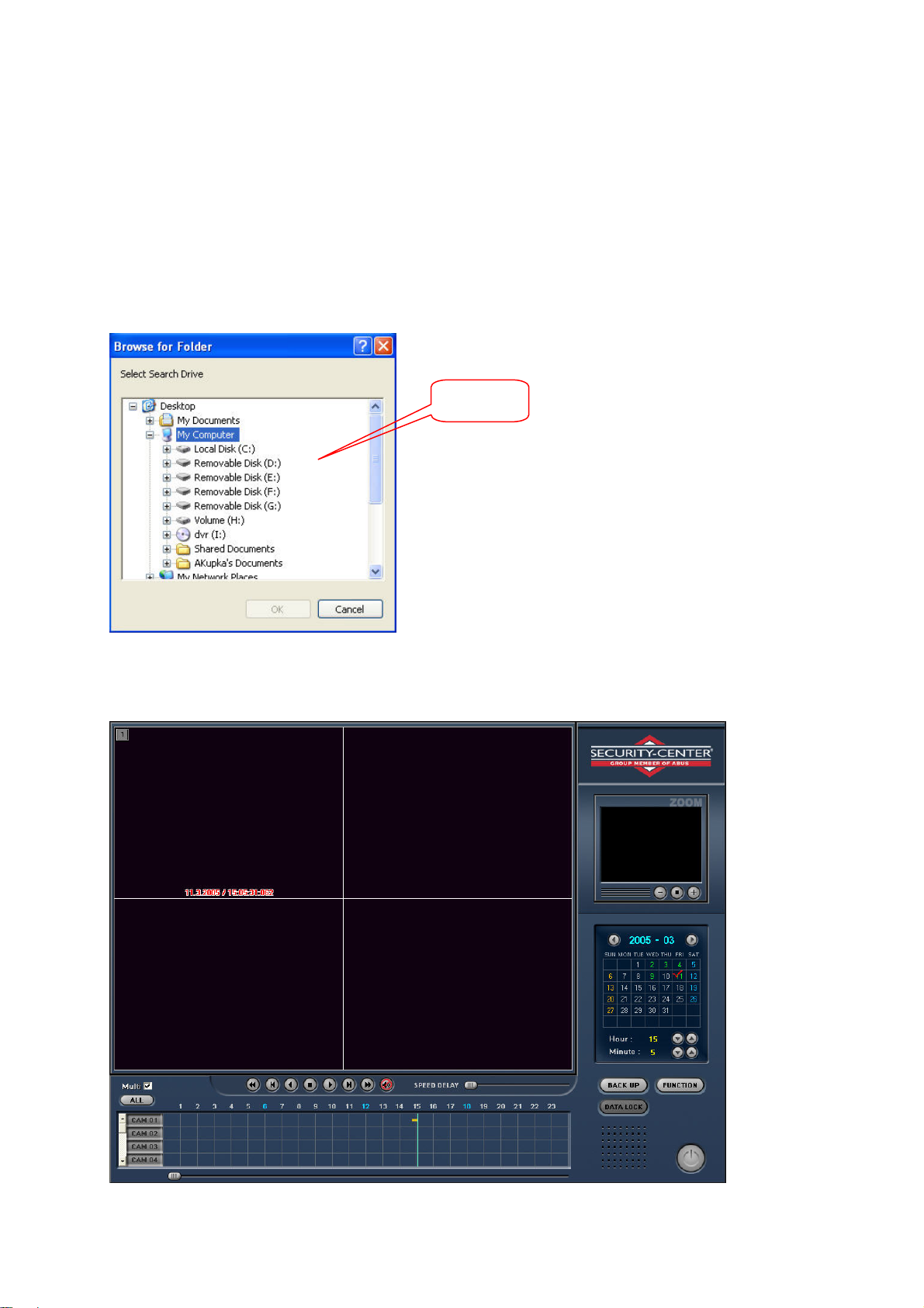
DigiProtect Searcher
p
The DigiProtect Searcher is on the software CD. With this program, you can analyse recorded and
saved surveillance data on any PC.
Select the [DigiProtect Client] directory on the software CD supplied and run “setup.exe”. Follow the
instructions on the screen and complete the installation correctly. Now start the Searcher via
[DigiProtect Server] on the Windows desktop.
You are asked to specify a path containing the saved data. Confirm with [OK].
Select a
ath
The Searcher user interface contains all functions of the playback screen. You can search for data,
print pictures, make AVI files or save pictures, etc.
101
Page 45
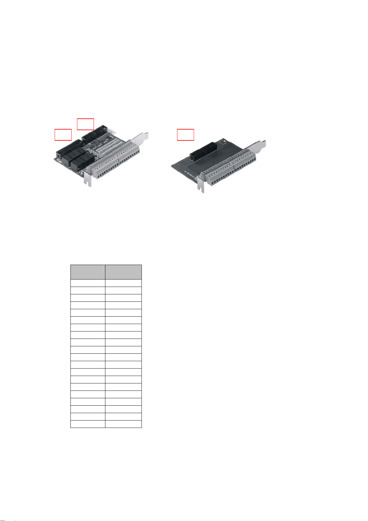
3
2
Installing the alarm I/O card
The I/O card (optional, Art. No. TV8812) enables you to connect up to 16 sensors to the surveillance
system. The I/O card also has 8 relay outputs for connecting external equipment. The I/O card needs
2 PCI sockets in your PC.
Switch the PC off and pull the mains plug out. Open the PC cabinet. Connect the sensor card with the
alarm card via connectors 2 and 3. Use the short flat cable provided. Connect the recorder card to the
sensor card (connector 1) using the second flat cable. Now plug the sensor card into a free PCI socket
and the alarm card into any free socket. Please use the provided power connector to connect the
sensor card with the power supply of the PC. Close the PC cabinet and switch the PC on.
The pin connections of the alarm and sensor cards is shown on the alarm card.
Alarm card Sensor
NO8 GND
COM8 GND
NO7 GND
COM7 GND
NO6 16
COM6 15
NO5 14
COM5 13
NO4 12
COM4 11
NC4 10
NO3 09
COM3 08
NC3 07
NO2 06
COM2 05
NC2 04
NO1 03
COM1 02
NC1 01
Sensor card
card
Alarm card:
Up to 8 outputs (24V DC, 1A) can be connected;
1-4 can be switched to NO (Normally Open) and
NC (Normally Closed) and 5-8 only to NO.
Sensor card:
You can connect 16 sensor inputs to the system.
The pin contacts can be set to NO or NC in the
Server software setup.
Alarm card
102
Page 46
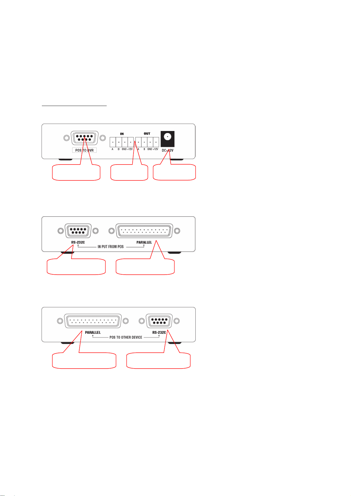
POS function
With the POS function of the DigiProtect system, you can display and save the transaction data of a
POS system and its video pictures. The data is shown on the live video screen and can be analysed
and saved via the playback screen. The format used is Excel.
Connecting the POS box
POS to DVR IN / OUT
RS-232C
INPUT FROM POS
PARALLEL
POS TO OTHER
POS to DVR: Connection between
POS box and
surveillance system (9
pin RS232C)
IN / OUT: RS485 connection to
DC+12V
or from another POS
box
DC+12: Power supply 12V DC
/ 500 mA
RS-232C: RS232C input signal
from POS system
(direct link)
PARALLEL: Parallel connection
from POS system
PARALLEL
INPUT FROM POS
PARALLEL: Parallel-Anschluss zu
anderer POS-Box
RS-232C: RS-232C-Ausgang zu
RS-232C
POS TO OTHER
anderer POS-Box
(Cross-Link)
103
Page 47
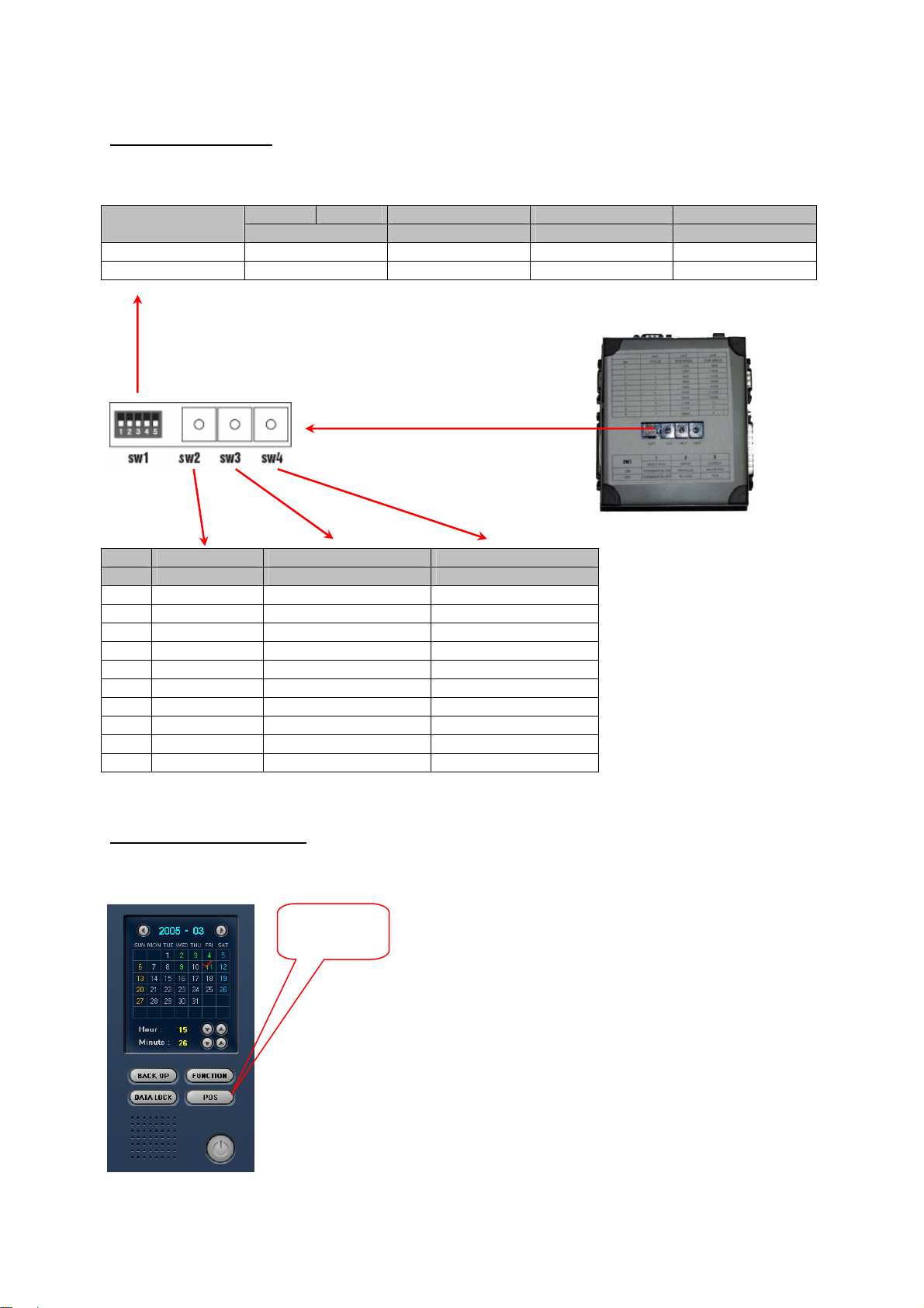
Setting up the POS box
The following switch positions are shown on the base of the POS box:
1 2 3 4 5 SW1
Other POS Box MULTI POS INPUT OUTPUT
ON Terminal ON Terminal ON PARALLEL MULTI-POS
OFF Terminal OF F Terminal OFF RS-232C POS
SW2 SW3 SW4
No. POS ID POS Speed DVR Speed
0 0 1200 9600
1 1 2400 14400
2 2 4800 19200
3 3 9600 38400
4 4 14400 57600
5 5 19200 115200
6 6 38400 128000
7 7 57600 X
8 X 115200 X
9 X 128000 X
Setup in surveillance system
Start the POS function on the playback screen.
POS function
104
Page 48
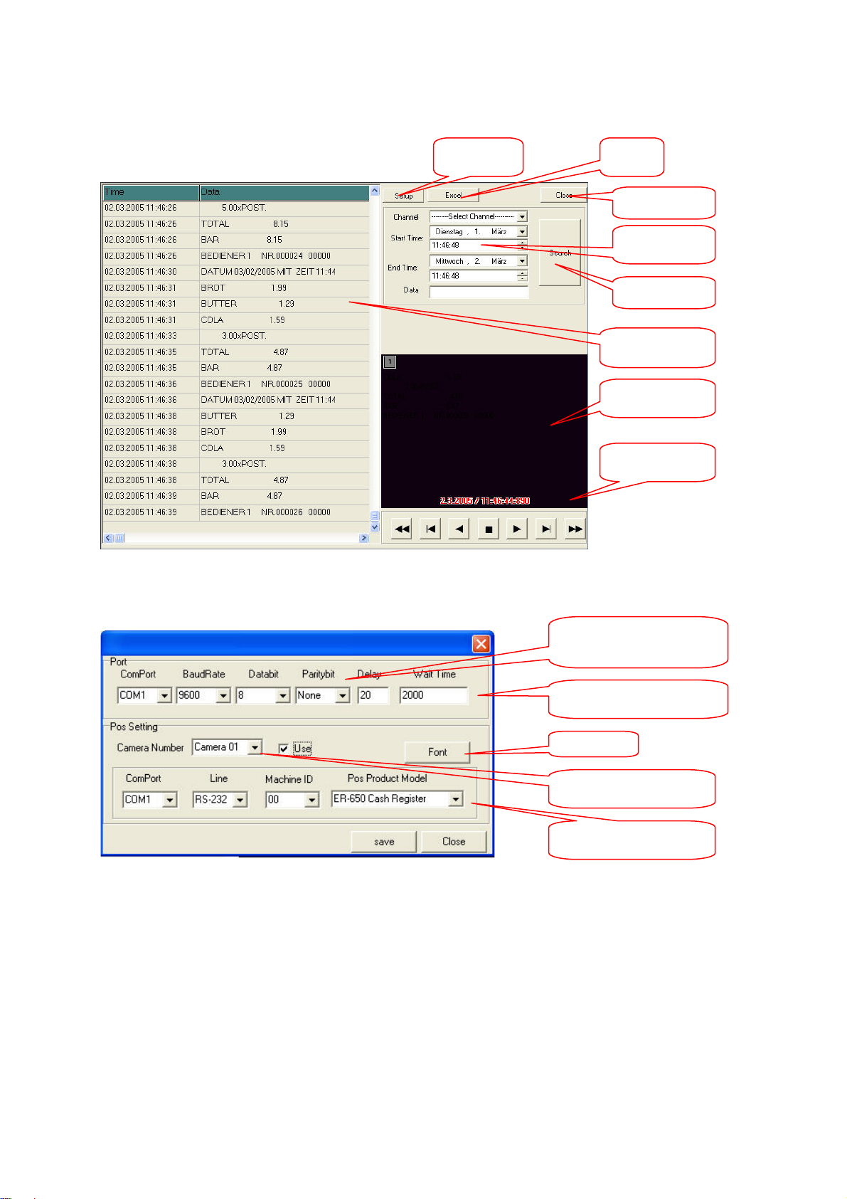
The POS screen opens.
p
Setup
Excel
Close
Search
arameters
Search
Transaction data
Video picture
Playback bar
Click [Setup].
Communication settings of
COM port
Delay / Wait Time
Font
Camera no.
POS settings
Set the correct communication parameters of the COM port. [Delay Time] sets the delay time for
displaying the data of each article after entry in the POS system. [Wait Time] defines the delay time for
the transmission from the POS system to the surveillance system for the accounting of all articles.
Select a camera that you want to associate with a specific POS ID. Enter the connection data and the
type of POS system. The ER-650 Cash Register supports following protocols: SAM SRP-100
(Samsung), SAM SRP250, SAM SRP-300, SAM SRP 350, CITIZEN 3550/3551/810/230, EPSON TMT88-2/U200/U295/U300/325/375/STAR SP200/STAR SP298/STAR SP300/STAR TSP200. Then
close the window.
105
Page 49
Analysing transaction data
g
The POS data is automatically displayed in the video picture of the respective camera. To analyse the
data, change to the POS screen under [Search / POS].
The transaction data is shown on the left with date and time.
Click a data row: the video screen shows the associated video picture. Play back the video data using
the buttons in the playback bar. If necessary, you can save the video data in the playback screen as
described above.
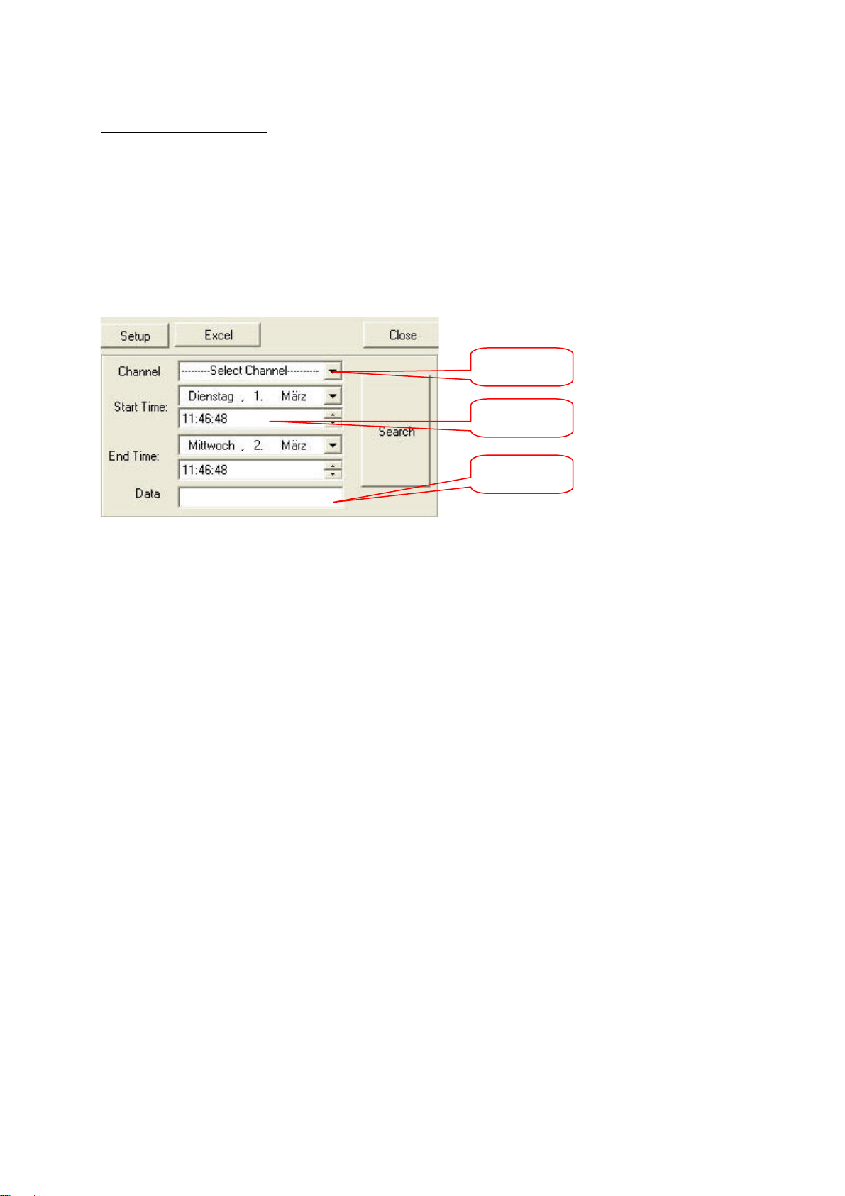
You can search for specific data via the search mask.
Channel no.
Period
Search
strin
/data
Define a channel and period for the search. Under [Search string/Data], enter the text to be searched
for (e.g., article name, assistant). Click [Search]. All found data is shown in the list on the left.
You can export the data in Excel format. Excel must first be installed in the surveillance system (not
part of the scope of delivery).
106
Page 50
New Functions – Version 6.20x
The new functions – card extension, dual-monitor and hybrid function – are available for card models
TV8800, TV8801, TV8802, TV8803, TV8804, TV8805, TV8806 and TV8807 only.
Card extension
The number of channels of the Digi-Protect System can be doubled in this version – i.e., if for example
a 4-channel realtime card is already installed in the system, a second card of the same type (4channel realtime) can be added to extend the number of channels to eight (realtime). A free PCI slot is
needed for the second PCI card.
Procedure:
1. First uninstall the current Digi-Protect software.
2. Switch off the PC, disconnect it from the mains electricity supply, and open the PC.
3. Install the second PCI recording card of the same type in a free PCI slot and close the PC.
4. Start the PC and install the necessary drivers. The number of drivers has doubled due to the
additional PCI card.
5. Now install the current software (V6.20x) matching your previous recording card.
6. After starting the Digi-Protect software, select “Setup / Standard / Set Channel” and then
select the required number of channels.
Dual-monitor function
The dual-monitor function allows you to connect a secondary monitor to the Digi-Protect surveillance
system. To make this possible, a graphics card with 2 monitor outputs must be installed in the system.
In the Windows display properties, the secondary monitor output must be enabled – i.e., the Windows
desktop must be extended to the secondary monitor.
For further questions on enabling the secondary monitor output on your graphics card, contact the
graphics card manufacturer.
Functions:
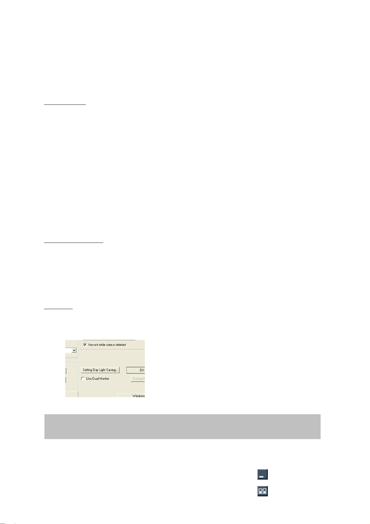
1. If a graphics card with 2 monitor outputs is installed in the system, you can now enable the dualmonitor function in the Digi-Protect Software under [Setup / Standard].
IMPORTANT: If no graphics card with 2 monitor outputs in installed but the DualMonitor function is enabled, you may have problems with display and stability.
2. Following activation, the channels are displayed as on the main monitor (e.g., quad view). You can
still choose between different views.
3. If necessary, you can click the Minimize button to minimize the view on
the secondary monitor.
107
Page 51
Click the dual-monitor icon on the main monitor to restore the original view on the secondary
monitor.
4. To hide the toolbars, right-click while the mouse pointer is in the secondary monitor area. Click
again to restore the view.
5. The dual-monitor function now offers you a further feature
in the event of anything happening. If an event occurs
(motion, alarm, …), the corresponding channel can be
shown full-screen on the secondary monitor.
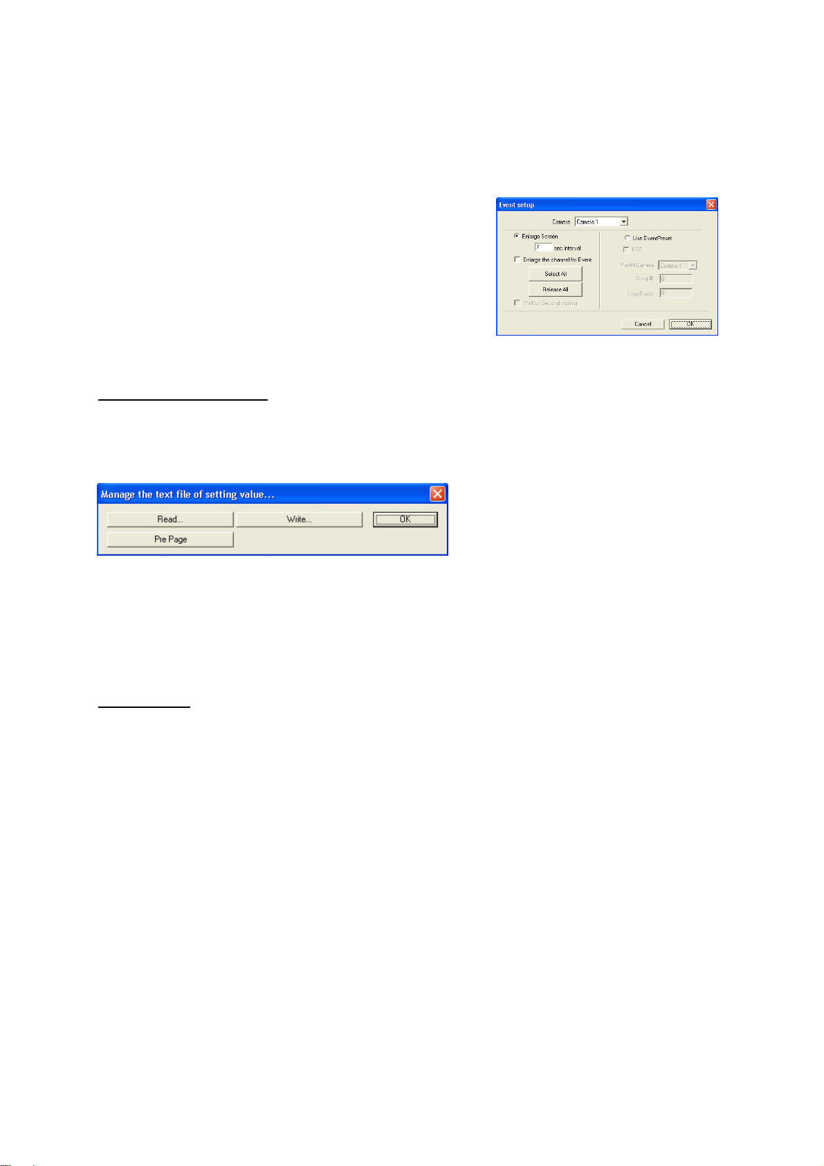
Under [Setup / Record / Event setup], select “Print by
Second monitor”. The corresponding channel is now
shown full-screen on the secondary monitor but not fullscreen on the main monitor.
6. Click the [Change Primary Secondary] button in the [Setup
/ Standard] menu to switch between the main monitor and the secondary monitor if required.
Saving the configuration file
This function allows you to save the complete configuration of the Digi-Protect system and reactivate it
when required. Under [Setup], click [Manage the text file of setting value …] at the bottom of the setup
screen.
Click the [Write…] button to save the configuration file of the system. The file name extension is
“*.sat”. Enter a file name and click “Save”. The configuration is now saved.
You can load a configuration file by clicking [Read…].
Hybrid function
The hybrid function enables you to integrate DIGILAN network cameras in the Digi-Protect system.
Only TV7200 and TV7201 cameras and the video-stream of the TV7202 video server are currently
supported (no Dome control function).
An enabled web camera channel is connected to the respective BNC video input. The number of
channels (BNC + web cameras) cannot exceed the max. channel capacity of the PCI recording card.
The following figure shows the [Web Camera] menu. Open this menu by clicking the [Setup] button.
108
Page 52
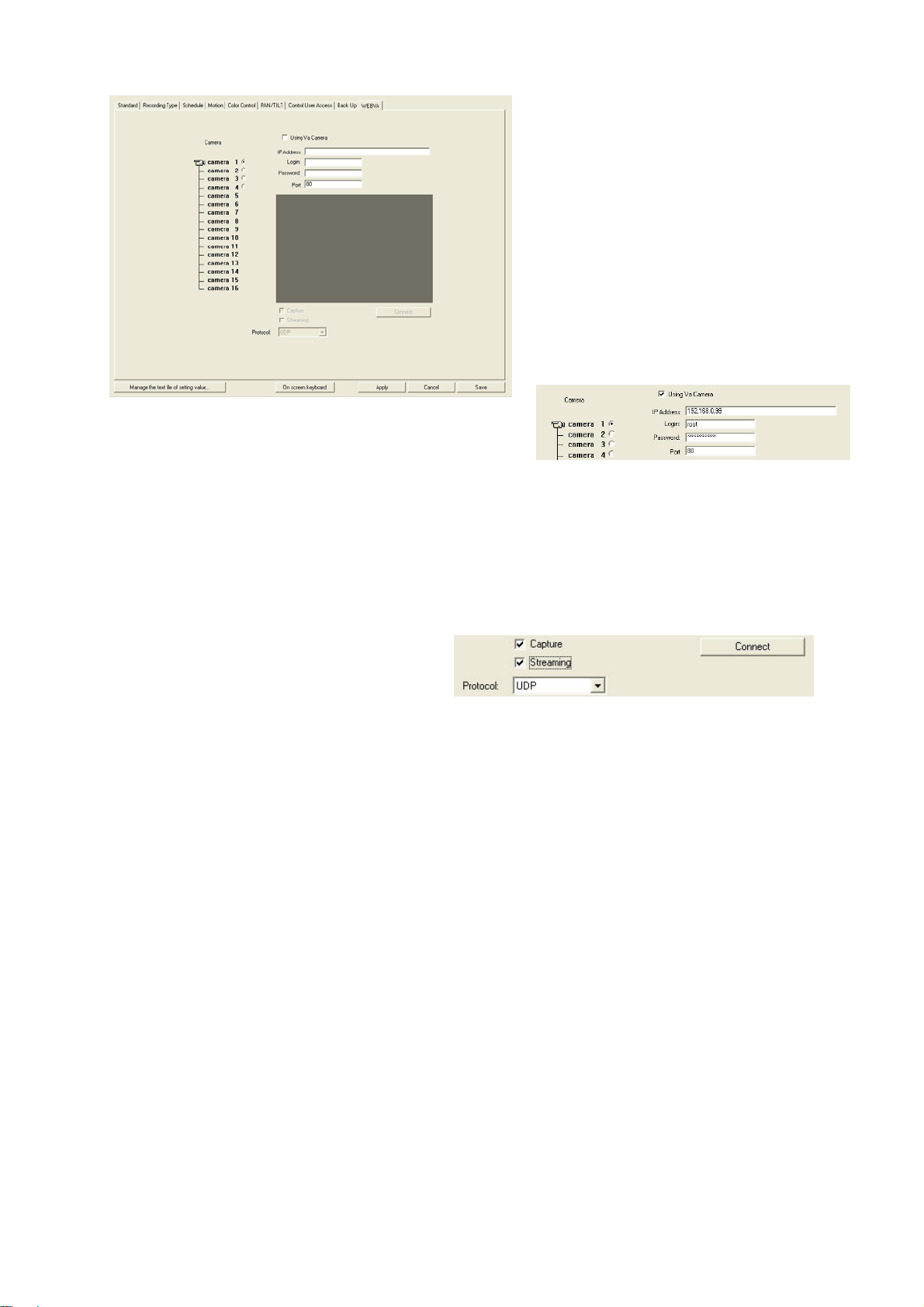
On the left, you can select a channel for
the incoming web camera signal.
Enter camera access data on the right
(enabling, IP address, login, password,
port).
At the bottom are options for
transmission and storage type.
Using Va Camera: Set the check mark to use a web
camera on this channel.
IP Address: Address or domain name of the web camera.
This address must be configured in the web camera or defined automatically by a DHCP server.
Login: The login name for the administrator is required; for DigiLan web cameras, it is always “root”.
Password: Enter the administrator password.
Port: Enter the http port number used. This port must be configured in the web camera.
There are further options under the preview
picture.
Capture: The web camera is shown on the
live screen. The recording is made in http
mode at 1 frame per second. You can delay data display on the screen. The camera is shown in the
same way on the secondary monitor.
Streaming: The web camera is shown on the live screen, with camera information at the top and
bottom. No recording is made. The camera is not shown on the secondary monitor. The max. possible
resolution is 352x288 pixels.
Capture + Streaming: The camera is shown on the live screen and on the secondary monitor. The
camera signal is prepared for recording. Select the recording type under [Setup / Record] (e.g. motiontriggered recording). The same recording types as for analogue cameras are available. The max.
possible resolution is 352x288 pixels.
Protocol: Select between UDP (no backup data), TCP (with backup data) and HTTP (single-frame
mode, 1 frame/sec.).
109
Page 53
Password manager
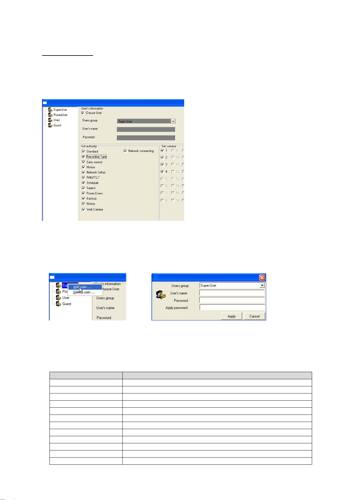
Note the following important changes to the password manager in Version 6.20x. The 3 areas (for
primary password, user setup [Setup / Standard] and network user settings [Setup / Network]) are now
combined in a single password manager under [Setup / Standard / Set Password]. The password
manager now looks like this:
To install a user:
1. First click [Add] on the left or right-click the left of the screen.
2. Select a user group type: Super User, Power User, User, Guest. The user groups have different
user permissions. You can change these permissions at any time later.
3. Enter a user name, a password and the password confirmation. Click [Apply].
4. The following table shows the different user permissions. Set the check-mark to use a permission.
Permission Meaning
Standard Permission for [Setup / Standard] menu item
Recording Type Permission for [Setup / Record] menu item
Color Control Permission for [Setup / Color control] menu item
Motion Permission for [Setup / Motion] menu item
Network Setup / Network Permission for [Setup / Network] menu item
PAN/TILT Permission for [Setup / PAN/TILT] menu item
Schedule Permission for [Setup / Schedule] menu item
Search / Search Permission for access to search screen
Power Down Permission for switching off system
Backup Permission for [Setup / Backup] menu item
History Permission for [Setup / History] menu item
Web Camera / Web Permission for [Setup / Web Camera] menu item
110
Page 54
Camera
Set Camera Enabled cameras are visible to the user.
Select the permissions required for the user and then click [Save] and [Close].
For every system access, whether direct at the PC or using client software / web client, a valid user
name and password now have to be entered.
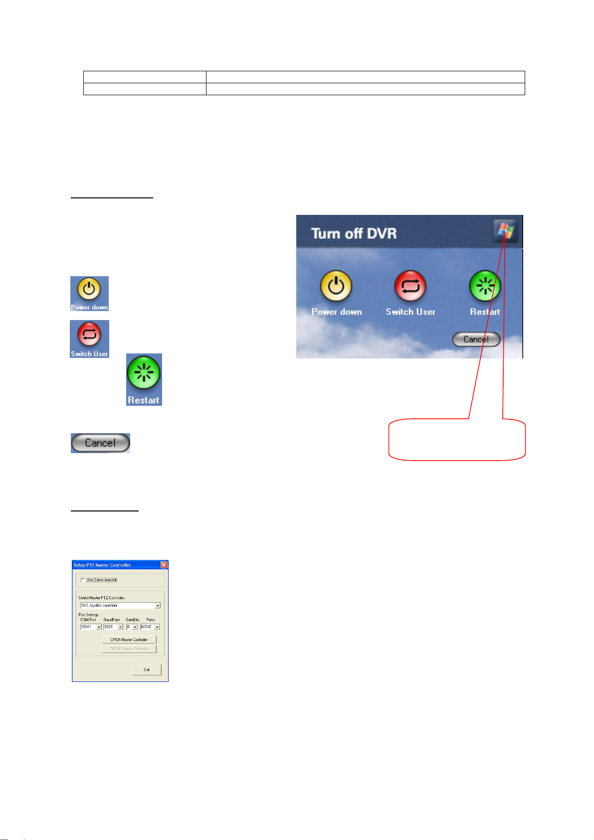
Power down mode
After you click the “Power down” icon on the
playback screen, the following window is
displayed in Version 6.20x: You now have the
following options:
system.
The software and the PC are
completely shut down.
Press to change user.
Click to reboot the
Click to cancel.
Exit to WindowsDesktop
Joystick control
Dome (PTZ/PanTilt) cameras can now be controlled using a joystick in this version (tested models:
Logitech® Extreme
TM
3D Pro, Logitech® AttackTM 3). The function was tested using the Highspeed
TV7090/TV7094 motor-dome camera.
Connect the joystick to a USB port of your PC. Now enable “Use Game
Joystick” under [Setup / PAN/TILT / Master Controller…].
If activation is successful, an info box opens. This box opens at every
software restart and must be confirmed.
The following table shows the control functions of the joystick.
111
Page 55

Joystick control commands
Button + joystick action PanTilt camera function
Button #1 + forwards Up
Button #1 + backwards Down
Button #1 + left Left
Button #1 + right Right
Button #1 & #2 + forwards Zoom in
Button #1 & #2 + backwards Zoom out
Button #1 & #2 + left Zoom in
Button #1 & #2 + right Zoom out
Button #3 Focus near
Button #4 Focus distant
Button #5 Close IRIS
Button #6 Open IRIS
Button #7 Select “camera channel”
Button #8 Select “Go to preset number”
Button #9 Focus
Button #10 Auto IRIS
Button #11 Auto pan
Button #12 Stop auto pan (not Logitech® AttackTM 3)
E-mail authentication
If authentication is required for sending e-mails, you can set this is in the respective e-mail function
dialog boxes:
– [Function / Auto E-mail / Setup E-Mail… / Need Authentication… / Setting…]
– [Setup / Backup / Send E-Mail… / Need Authentication… / Setting…]
Enter the access name and the password of the e-mail account.
112
 Loading...