

Page 1

DigiPoS Millennium
Technical Manual
Socket 370 Series
Manual Version 2.1
May 2004
Page 2

DigiPoS Millennium Technical Manual
USER’S NOTICE
No part of this manual, including the products and software described in it, may be
reproduced, transmitted, transcribed, stored in a retrieval system, or translated into any
language in any form or by any means, except documentation kept by the purchaser for
backup purposes, without the express written permission of DigiPoS Systems.
DigiPoS Systems provides this manual “AS IS” without warranty of any kind, either
express or implied, including but not limited to the implied warranties or conditions of
merchantability or fitness for a particular purpose. In no event shall DigiPoS Systems, its
directors, officers, employees or agents be liable for any indirect, special, incidental, or
consequential damages (including damages for loss of profits, loss of business, loss of
use or data, interruption of business and the like), even if DigiPoS Systems has been
advised of the possibility of such damages arising from any defect or error in this manual
or product.
Specifications and information contained in this manual are provided for informational use
only, and are subject to change or update at any time without notice, and should not be
construed as a commitment by DigiPoS Systems. DigiPoS Systems assumes no
responsibility or liability for any errors or inaccuracies that may appear in this manual,
including the products and software described in it.
Updates to this manual and additional information may be found on the Internet at
http://www.digipos-systems.com/
For any drivers associated with this DigiPoS, please contact your supplier/distributor or
you can find the latest versions available for download on the Internet at
http://www.digipos-systems.com/
FCC Radio Frequency Interference Statement
This equipment has been tested and found to comply with the limits for a class A digital
device. These limits are designed to provide reasonable protection against harmful
interference when the equipment is operated in a commercial environment. This
equipment generates, uses and can radiate radio frequency energy and, if not installed
and used in accordance with the instruction manual, may cause harmful interference to
radio communications. Operation of this equipment in a residential area is likely to cause
harmful interference, in which case the user will be required to correct the interference at
this own expense.
Notice
The changes or modifications not expressly approved by the party responsible for
compliance could void the user’s authority to operate the equipment.
All brand names and registered trademarks mentioned in this manual are the property of
their respective owners and their use here is for reference purposes only.
Page 2 of 81
Page 3

DigiPoS Millennium Technical Manual
SAFETY INSTRUCTIONS
• Always read the safety instructions carefully.
• Keep this Manual for future reference.
• Keep this equipment away from humidity and dust.
• Lay the equipment on a reliable flat surface before setting it up.
• The openings on the enclosure are for air convection, hence protecting the equipment
from overheating. DO NOT COVER THESE OPENINGS. For a more detailed
explanation about ventilation requirements, please check the on-line documentation
available at:
http://www.digipos-systems.com/
• Make sure the voltage of the power source (mains) conforms within the permitted
range before connecting the equipment to the power inlet.
• Place the power cord in such a way that people cannot step on it. Do not place
anything over the power cord.
• ALWAYS shut down the operating system and disconnect the unit from any power
sources before removing any connections (Keyboard, Mouse, etc..) or opening up the
unit to fit additional cards and or devices.
• All cautions and warnings on the equipment should be noted and adhered to.
• Never pour any liquid into the opening that could damage or cause electrical shock.
• If any of the following situations arise, have the equipment checked by qualified service
personnel:
o The power cord or plug is damaged
o Liquid has penetrated into the DigiPoS
o The equipment has been exposed to moisture
o The DigiPoS is not working well or you can not get it to work according to the
User’s Manual
o The DigiPoS has been dropped and damaged
o The DigiPoS has obvious signs of breakage or physical damage
• Do not leave this DigiPoS in a non air-conditioned environment with a storage
temperature above 60ºc (140ºf) as it may damage the equipment.
• For reasons of safety, gloves should be worn when assembling the DigiPoS after any
work has been carried out.
NOTE
• The technical descriptions and specifications of the DigiPoS Millennium are subject
to change without notice.
ACHTUNG
• Wir behalten uns Änderungen der technischen Beschreibungen bzw.
!
Spezifikationen vor.
注意事項
•
本說明書所列規格僅供參考, 本公司保留產品修改變更之權利.
• 為了您的安全, 拆裝PC內部組件時請戴白手套以防割傷.
CAUTION
Page 3 of 81
Page 4

DigiPoS Millennium Technical Manual
There is a danger of explosion if the CMOS battery is incorrectly replaced.
Replace only with the same or equivalent type of battery. Please Contact you’re
nearest DigiPoS Systems office for further information and or assistance.
Page 4 of 81
Page 5

DigiPoS Millennium Technical Manual
CONTENTS
INTRODUCTION ................................................................................................................ 9
Key Features....................................................................................................................................... 9
VENTILATION REQUIREMENTS .................................................................................... 11
Cavity Size......................................................................................................................................... 11
Enclosed Spaces.............................................................................................................................. 11
Under Counter Mounting .................................................................................................................12
TECHNICAL SPECIFICATIONS ...................................................................................... 13
CPU & FSB Clock Speeds ............................................................................................................... 13
Memory..............................................................................................................................................13
BIOS................................................................................................................................................... 13
VIA 82C686B ‘South Bridge’............................................................................................................14
PCI to ISA Bridge .................................................................................................................. 14
UltraDMA-33 / 66 / 100 Master Mode PCI EIDE Controller .................................................. 14
Integrated Super IO Controller .............................................................................................. 15
Voltage, Temperature, Fan Speed Monitor and Controller................................................... 15
Universal Serial Bus Controller .............................................................................................15
System Management Bus Interface ......................................................................................15
PC99-Compatible Power Management................................................................................. 15
Plug and Play Controller........................................................................................................16
VIA VT8604 ‘North Bridge’...............................................................................................................16
General.................................................................................................................................. 16
Advanced, High-Performance Memory Controller ................................................................17
Accelerated Graphics Port (AGP) Controller......................................................................... 17
Integrated Savage4 2D/3D/Video Accelerator ......................................................................17
3D Rendering Features......................................................................................................... 17
2D Hardware Acceleration Features .....................................................................................18
Motion Video Architecture ..................................................................................................... 18
Flat Panel Monitor Support.................................................................................................... 18
Concurrent PCI Bus Controller.............................................................................................. 18
Full Software Support............................................................................................................18
Onboard Audio ................................................................................................................................. 18
Onboard LAN Adapter .....................................................................................................................19
Options .............................................................................................................................................. 19
PCI Cards.............................................................................................................................. 19
Disk On Module Port .............................................................................................................19
Dual VGA out card ................................................................................................................19
CD-ROM/ CD-R/ CD-RW ...................................................................................................... 19
Digital Flat Panel Output (DVI).............................................................................................. 19
Important Notes................................................................................................................................ 20
Page 5 of 81
Page 6

DigiPoS Millennium Technical Manual
THE SYSTEM................................................................................................................... 21
Front Panel Orientation ...................................................................................................................21
Rear Panel Orientation..................................................................................................................... 22
Internal System Orientation ............................................................................................................ 23
The Heat Pipe, Air Tunnel & CPU....................................................................................................24
Jumper Settings and Connections.................................................................................................27
Jumpers.................................................................................................................................27
CPU Switch Settings .............................................................................................................27
Connections...........................................................................................................................28
Riser Card Orientation .....................................................................................................................28
Motherboard Orientation ................................................................................................................. 29
I/O Interfaces & Power Connectors ................................................................................................ 31
RS232 Standard Serial Ports ................................................................................................ 31
Parallel Port........................................................................................................................... 31
USB Ports.............................................................................................................................. 32
PS / 2 Keyboard & Mouse Ports ........................................................................................... 32
Windows Shortcut Keys ........................................................................................................32
LAN Connector......................................................................................................................33
VGA Connector .....................................................................................................................34
Hosiden Connector................................................................................................................ 34
Power Supply Connector.......................................................................................................34
2.5mm Barrel Connector ....................................................................................................... 35
POWER DISTRIBUTION ON THE DIGIPOS MILLENNIUM ............................................ 36
Configuration.................................................................................................................................... 36
Correct Fuse Ratings ............................................................................................................37
Power Board Configuration ................................................................................................... 37
Application............................................................................................................................. 37
Typical Voltage Requirements ..............................................................................................38
Continuous and Peak Current Capacity................................................................................ 38
ONBOARD DIAGNOSTICS FOR THE DIGIPOS MILLENNIUM ..................................... 39
Diagnostic Overview ........................................................................................................................39
Diagnostic Procedure ...................................................................................................................... 39
Printer Test............................................................................................................................ 40
Customer Display Test.......................................................................................................... 40
Keyboard Test .......................................................................................................................41
Magnetic Card Test............................................................................................................... 42
Bar Code Scanner Test......................................................................................................... 43
Page 6 of 81
Page 7

DigiPoS Millennium Technical Manual
BIOS SET-UP OVERVIEW............................................................................................... 44
Main BIOS Screen ............................................................................................................................45
Details....................................................................................................................................45
Standard CMOS Features ................................................................................................................ 46
General Details...................................................................................................................... 46
IDE Options Sub Menus........................................................................................................48
Details....................................................................................................................................48
Advanced BIOS Features ................................................................................................................50
Details....................................................................................................................................50
Advanced Chipset Features ............................................................................................................ 53
Details....................................................................................................................................53
Integrated Peripherals .....................................................................................................................55
Details....................................................................................................................................55
Power Management Setup............................................................................................................... 59
Details....................................................................................................................................59
Power Management Sub Menu............................................................................................. 60
Wake Up Events Sub Menu .................................................................................................. 61
PnP/PCI Configurations................................................................................................................... 62
Details....................................................................................................................................62
PC Health Status ..............................................................................................................................64
Details....................................................................................................................................64
Frequency/Voltage Control .............................................................................................................65
Details....................................................................................................................................65
Operating System Dependant Settings.......................................................................................... 66
DOS.......................................................................................................................................66
Windows 95 & NT.................................................................................................................. 67
Windows 98, Me, 2000 & Xp................................................................................................. 67
Windows Xp Special Notes ................................................................................................... 67
FAULT DIAGNOSIS......................................................................................................... 68
Power Up Test Sequence ................................................................................................................69
Input / Output Port Testing.............................................................................................................. 70
PS/2 Keyboard Port...............................................................................................................70
PS/2 Mouse Port ................................................................................................................... 70
COM Ports............................................................................................................................. 70
VGA Port ............................................................................................................................... 70
LAN Port................................................................................................................................ 71
Parallel Port........................................................................................................................... 71
RJ12 Cash Drawer Loop Through ........................................................................................71
Sound Connectors................................................................................................................. 71
USB Connectors.................................................................................................................... 71
Powered Port Testing ......................................................................................................................72
Voltage Level Checking.........................................................................................................72
Peripheral Component Check ......................................................................................................... 74
Page 7 of 81
Page 8

DigiPoS Millennium Technical Manual
st
1
Level Fault Finding...................................................................................................................... 75
System Does Not Boot ..........................................................................................................75
No VGA Output .....................................................................................................................75
Floppy disk failure .................................................................................................................75
Hard disk failure ....................................................................................................................75
CD ROM Failure.................................................................................................................... 76
COM port failure ....................................................................................................................76
Parallel Port Failure...............................................................................................................76
Disk On Chip Failure ............................................................................................................. 76
Onboard LAN Failure ............................................................................................................76
System Hold or Freeze.......................................................................................................... 76
TEST SHEET.................................................................................................................... 78
WARRANTY POLICY....................................................................................................... 80
Limited Warranty ..............................................................................................................................80
Warranty Return Procedures .......................................................................................................... 80
THE FOLLOWING SHALL VOID WARRANTY ................................................................................ 80
DIGIPOS SYSTEMS GLOBAL OFFICE LOCATIONS..................................................... 81
Page 8 of 81
Page 9

DigiPoS Millennium Technical Manual
Introduction
Congratulations on the purchase of your DigiPoS Retail System!
You are now the owner of a state-of-the-art DigiPoS Retail System. The DigiPoS Retail
System is a solution that offers enhanced features, speed and performance combined with
exceptional reliability. It is also a PC that is unrivalled by other conventional Pentium
based PCs within the EPoS industry.
Key Features
Component Description
CPU Supports Socket 370 Intel Celeron / PIII/VIA Cyrix C3 CPUs
CPU CLOCK 266 MHz to 1GHz
MAIN MEMORY Notebook SO-DIMM X 1 up to 512MB (SDRAM or EDO)
Enhanced ACPI 1.0 / PnP / APM / DMI / ESCD / PCI bus 2.1 / OnNow /
BIOS
DRAM ECC Quick Boot / HW Monitor (LDCM) / I-O Pre-set IRQ / Spread
Spectrum / PC98 compliant
CACHE MEMORY 512KB P.B. SRAM
EXPANSION SLOTS
SERIAL PORTS
PARALLEL PORT One LPT port (SPP / EPP / ECP) IRQ and address selectable by BIOS
USB TWO USB ports supporting Windows 95/98/Me/2000/Xp
FDD 1.44MB / 3.5" FDD x 1
ENHANCED PCI IDE
AGP GRAPHICS
ADAPTER
Riser Card with 3 FREE Slots:
1 x ISA, 2 x PCI and 1 x IDE2 CD-ROM connector
COM1, COM2, COM3, COM4 (COM3/4 output on riser card).
IRQ & I/O address selection by BIOS (Jumper less).
On board PCI Bus Master IDE1/2 controller with Windows utility.
Supports Ultra DMA/66
VIA 8604 AGP with shared memory from 2MB up to 32MB.
Features include:
Support for 4X AGP VGA controller
Support for 3D / 2D Graphics Accelerator
Support for DVD Video Accelerator
Support for VESA DPMS VGA Monitor for Power Management
Direct X, VPE, MPEG2
NT4.0 / 5.0, Windows95/98/Me/2000/Xp utility
APM / ACPI 1.0
Supports VESA DPMS VGA monitor for power management
PC98 compliant
CRT and LCD TMDS output (Optional)
Supports dual monitor output (optional) under Windows 98/Me/2000/Xp
ACPI / NT4.0 / 5.0 (NDIS 5)
ONBOARD LAN
(10/100Mbs
Auto sensing)
ONBOARD AUDIO AC97 CODEC on board
DISK ON CHIP With DigiPoS EPoS Diagnostics Utility
NT 4.0 / Win95/98 utility
Remote boot ROM
NT4.0/Win95/98 Utility
PC98 compliant
Enable or disable by BIOS set-up (Jumper less)
Page 9 of 81
Page 10

DigiPoS Millennium Technical Manual
Component Description
KEYBOARD PORT PS/2 type
MOUSE PORT PS/2 type
Front panel features include:
AC power on/off button
FRONT PANEL
BACK PANEL
3 LED indicators: Power On/Off, HDD state & LAN state
1.44MB FDD
Door for FDD and Power switch (with key lock)
Slim 24X CD-ROM or CD-R/ CD-RW (optional) drive bay
Back panel features include:
VGA CRT 15-pin DSUB connector
COM1/2/3/4 9-pin DSUB output connectors
LPT 25-pin DSUB connector
PS/2 Keyboard & Mouse connectors
LAN RJ-45 output connector
USB1 / USB2 connector
Audio line in / line out, microphone-in
2nd CRT and LCD TMDS output (optional)
TV S-Video and RCA connector output (optional)
One low-noise 50mm fan for power supply and HDD
THERMAL SOLUTION
AC POWER SUPPLY
AC POWER SOURCE AC 90V to 264V, 60Hz / 50Hz
CASE DIMENSIONS
S/W COMPATIBILITY
EXPORT PACKAGING Each pack measures 36 x 36 x 19cm and weighs 5.5kg net 6.5kg gross
TEMPERATURE
One low-noise 50mm fan for CPU heat-pipe (water cooling system)
and air tunnel
300W External Power Supply
(UL, CSA, VDE, EMI meets FCC *B*)
11"(W) x 11" (D) x 3" (H) (280 x 280 x 75mm)
(Excluding PSU)
DOS / OS2 V2.1 / SCO XENIX: V2.3.2 / SCO UNIX V3.2 / NOVELL /
WIN 3.1/95/98/Me/NT4.0/2000/Xp
Operating: 0ºC to 40ºC (without HDD up to 50ºC)
Storage: -25ºC to 70ºC
Page 10 of 81
Page 11
DigiPoS Millennium Technical Manual
m
V
A
Ventilation Requirements
Cavity Size
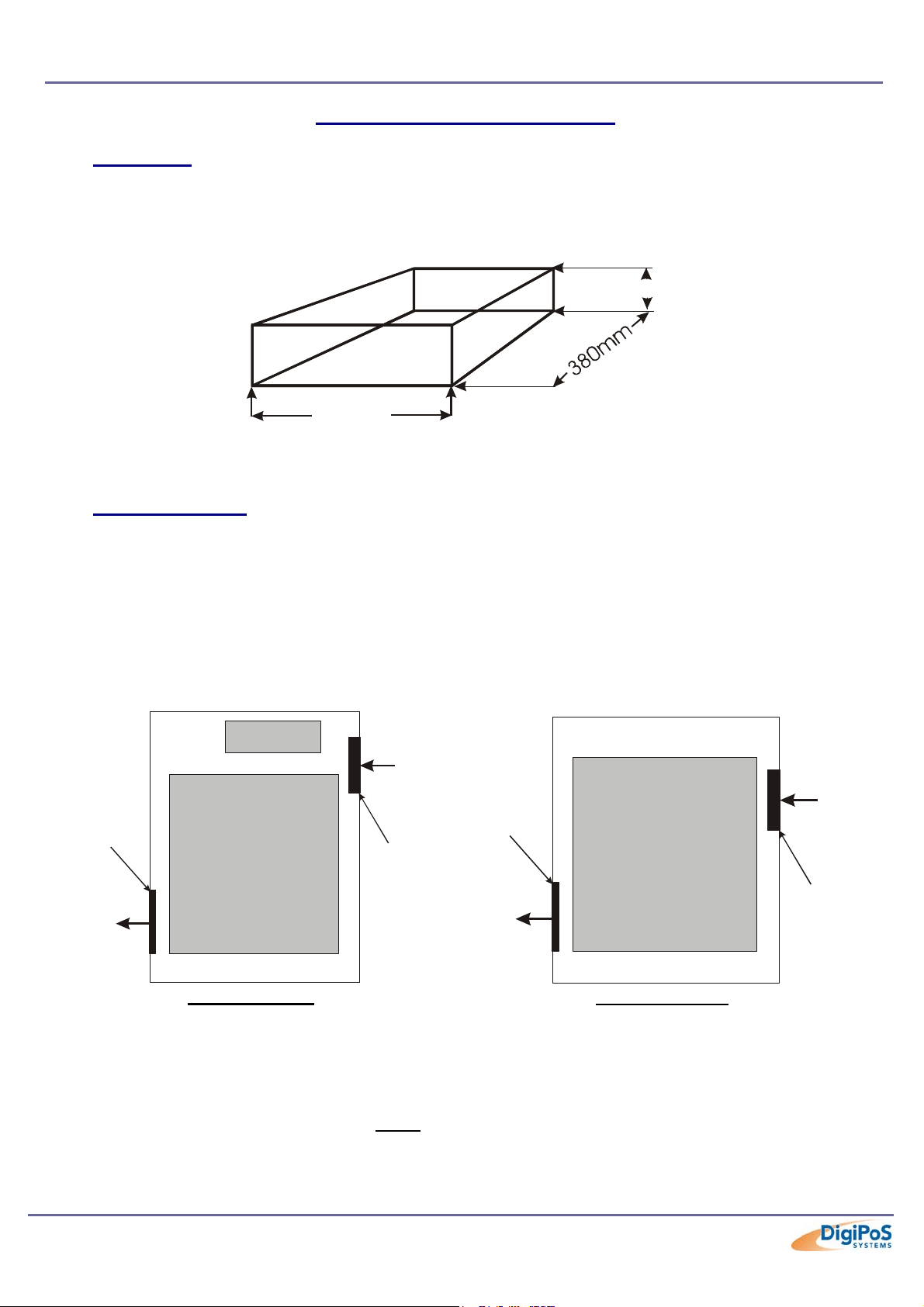
If the DigiPoS is to be located in a cavity, i.e. under the counter, the cavity dimensions
must be a minimum of 380mm long by 400mm wide by 120mm deep (excluding the
external PSU). A diagrammatic representation is as follows:
120mm
400m
Although this is the required space, the DigiPoS MUST be located centrally to prevent the
airflow from being disrupted through the ventilation holes in the sides of the case.
Enclosed Spaces
If the DigiPoS is to be located in an enclosed space, i.e. in a closed box or cabinet, there
must be sufficient airflow into and out of the enclosed space. Using the above cavity
space as an example, forced airflow would have to be fitted to prevent the DigiPoS from
overheating. As a general rule, the DigiPoS Millennium requires an airflow exchange rate
of a minimum of 25 CFM (Cubic Feet per Minute) excluding PSU or 30 CFM including
PSU when in an enclosed space.
The recommended location for these fans is as follows:
Exhaust Vent
Airflow
Direction
iew From Above
PSU
Rear
DigiPoS
Airflow
Direction
Exhaust Vent
30cfm Fan
Airflow
Direction
View From Above
Rear
DigiPoS
25cfm Fan
irflow
Direction
Front
Including PSU
Front
Excluding PSU
External PSU
DigiPoS Systems recommends that the external PSU for Millennium is not situated in the
same space as the DigiPoS to minimise heat build up in enclosed spaces. If this is
unavoidable, forced air ventilation must
be installed to provide adequate ventilation for the
DigiPoS & PSU heat dissipation devices.
Page 11 of 81
Page 12
DigiPoS Millennium Technical Manual
Under Counter Mounting
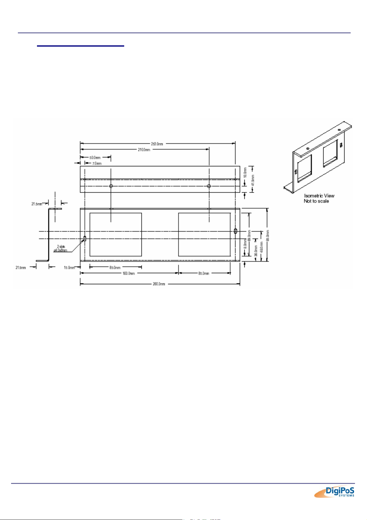
The DigiPoS can be mounted under the counter or on a secure vertical surface to
maximise the available space at the Point of Sale. In order to do this, a special bracket
must be used that has been specifically engineered for the DigiPoS. This bracket does not
obstruct the ventilation yet still provides a secure mounting without the need for drilling
holes in the case which will void the warranty.
DigiPoS Brackets
To fit the bracket, simply remove the case screw towards the rear of the DigiPoS and offer
up the bracket to the DigiPoS. Then, refit the screw and the DigiPoS can now be secured
in position.
The External PSU has mounting holes pre-formed in its case and does not require any
special brackets.
Please contact you’re nearest DigiPoS Systems Office for further details and availability
on these brackets.
Page 12 of 81
Page 13

DigiPoS Millennium Technical Manual
Technical Specifications
CPU & FSB Clock Speeds
The Central Processing Unit or CPU fitted in your DigiPoS will depend greatly on what
particular model of DigiPoS you have. The Following is a detailed list of the correct type
of CPU fitted to the DigiPoS Millennium and its respective settings:
CPU Type Intel Celeron
Package Type
Clock Speed 850Mhz
Front Side Bus Speed 100Mhz
L2 Cache Size 128Kb
FC-PGA
(Flip Chip - Pin Grid Array)
The thermal transfer pad on CPU heat pipe assembly can be easily damaged if the
heat pipe is removed and refitted several times. We therefore recommend that only
DigiPoS Systems or authorized agents for DigiPoS Systems attempt to remove the
heat pipe. Failure to comply with this notice shall void all warranties.
Memory
Each DigiPoS Millennium is fitted with a single module of memory. Commonly referred to
as laptop memory, the correct terminology for it is Small Outline Dual In-line Memory
Module or SODIMM for short. The specifications for this memory are as follows:
Pins 144 Pin Gold
Type SDRAM
Sizes 32, 64, 128, 256, 512Mb
Clock Speeds
*= Dependant on Front Side Bus setting according to CPU type.
*
32, 64Mb 100Mhz
128, 256, 512Mb 100 – 133Mhz
Should you wish to upgrade the memory in the DigiPoS, please contact DigiPoS
Systems for the specifications on the correct type of memory to be used. Using
inappropriate types of memory may significantly degrade the performance of your
DigiPoS and also void all warranties.
BIOS
The Phoenix BIOS is discussed in greater detail later on in this manual.
Page 13 of 81
Page 14

DigiPoS Millennium Technical Manual
VIA 82C686B ‘South Bridge’
Incorporating:
• PCI Expansion Slots
• ISA Expansion Slots
• IDE Ports
• Keyboard & Mouse Ports
• RS232 ‘Serial’ Ports
• Parallel Port
• USB Ports
• Hardware Monitoring
• Motherboard Resources
PCI to ISA Bridge
• Integrated ISA Bus Controller with integrated DMA, timer, and interrupt
controller
• Integrated Keyboard Controller with PS2 mouse support
• Integrated DS12885-style Real Time Clock with extended 256byte
CMOS RAM and Day/Month Alarm for ACPI
• Integrated USB Controller with root hub for 2 ports
• Integrated UltraDMA-33/66/100 master mode EIDE controller with
enhanced PCI bus commands
• PCI-2.2 compliant with delay transaction and remote power management
• Eight double-word line buffer between PCI and ISA bus
• One level of PCI to ISA post-write buffer
• Supports type F DMA transfers
• Distributed DMA support for ISA legacy DMA across the PCI bus
• Serial interrupt for docking and non-docking applications
• Fast reset and Gate A20 operation
• Edge trigger or level sensitive interrupt
• Flash EPROM, 4Mb EPROM and combined BIOS support
• Supports positive and subtractive decoding
UltraDMA-33 / 66 / 100 Master Mode PCI EIDE Controller
• Dual channel master mode PCI supporting multiple Enhanced IDE
devices
• Transfer rate up to 33MB/sec to cover PIO mode 4, multi-word DMA
mode 2 drives, and UltraDMA-33 interface
• Increased reliability using UltraDMA-66 transfer protocols
• Increased performance using UltraDMA-100 mode 5
• Thirty-two levels (double words) of pre-fetch and write buffers
• Dual DMA engine for concurrent dual channel operation
• Bus master programming interface for SFF-8038I rev.1.0 and Windows-
95 compliant
• Full scatter gather capability
• Support ATAPI compliant devices including DVD devices
• Support PCI native and ATA compatibility modes
• Complete software driver support
Page 14 of 81
Page 15

DigiPoS Millennium Technical Manual
Integrated Super IO Controller
• Supports 4 serial ports, parallel port, and floppy disk controller functions
• Programmable character lengths (5,6,7,8)
• Even, odd, stick or no parity bit generation and detection
• Programmable baud rate generator
• Independent transmit/receiver FIFOs
• Modem Control
• Plug and play with 96 base IO address and 12 IRQ options
• Multi-mode parallel port
o Standard mode (SPP), ECP and EPP support
• Floppy Disk Controller
• 16 bytes of FIFO
• Data rates up to 1Mbps
• Perpendicular recording driver support
• Plug and play with 48 base IO address, 12 IRQ and 4 DMA options
Voltage, Temperature, Fan Speed Monitor and Controller
• Monitoring of Five positive voltages (one internal), three temperatures
(one internal) and two fan-speed (CPU & PSU)
• Programmable control, status, monitoring and alarm facility for flexible
desktop thermal management
• Automatic clock throttling with integrated temperature sensing
• Internal core VCC voltage sensing
Universal Serial Bus Controller
• USB v.1.1 and Intel Universal HCI v.1.1 compatible
• Eighteen level (double words) data FIFO with full scatter and gather
capability
• Root hub and 2 functioning ports
• Integrated physical layer transceivers with optional over-current detection
status on USB inputs
• Legacy keyboard and PS/2 mouse support
System Management Bus Interface
• Host interface for processor communications
• Slave interface for external SMBus masters
PC99-Compatible Power Management
• CPU clock throttling and clock stop control for complete ACPI C0 to C3
state support
• PCI bus clock run, Power Management Enable (PME) control, and
PCI/CPU clock generator stop control
• Supports multiple system suspend types: power-on suspends with
flexible CPU/PCI bus reset options,
• suspend to DRAM, and suspend to disk (soft-off), all with hardware
automatic wake-up
• Multiple suspend power plane controls and suspend status indicators
• One idle timer, one peripheral timer and one general purpose timer, plus
24/32-bit ACPI compliant timer
Page 15 of 81
Page 16

DigiPoS Millennium Technical Manual
PC99-Compatible Power Management Cont.
• Normal, doze, sleep, suspend and conserve modes
• System event monitoring with two event classes
• Primary and secondary interrupt differentiation for individual channels
• Dedicated input pins for power/ sleep buttons and external modem ring
indicator
• Up to 12 general purpose input ports and 23 output ports
• Multiple internal and external SMI sources for flexible power
management models
• One programmable chip select and one micro controller chip select
• Enhanced integrated real time clock (RTC) with date alarm, month alarm,
and century field
• Thermal alarm on either external or any combination of three internal
temperature-sensing circuits
• I/O pad leakage control
Plug and Play Controller
• PCI interrupts steerable to any interrupt channel
• Steerable interrupts for integrated peripheral controllers: USB, floppy,
serial, parallel, audio, SoundBlaster, MIDI
• Steerable DMA channels for integrated floppy, parallel, and SoundBlaster
pro controllers
• One additional steerable interrupt channel for on-board plug and play
devices
• Microsoft Windows 95, Windows 98, Windows Me, Windows 2000 and
Windows Xp Plug and Play BIOS compliant
VIA VT8604 ‘North Bridge’
Incorporating:
• CPU Interface
• Memory Controller
• AGP Graphics Controller
• PCI Bus Controller
General
• High performance SMA North Bridge
• Integrated VIA Apollo Pro133A and S3. Savage4. in a single chip
• “P6-bus Desktop PC” member of VIA’s Apollo ProSavage integrated
graphics product line
• 64-bit Advanced Memory controller supporting PC100/PC133 SDRAM
and VCM
• High Performance CPU Interface
• Socket 370 (VIA Technologies VIA-Cyrix-III. and Intel Celeron.)
• 66/100/133 MHz CPU Front Side Bus (FSB)
• Built-in Phase Lock Loop circuitry for optimal skew control within and
between clocking regions
Page 16 of 81
Page 17

DigiPoS Millennium Technical Manual
General Cont
• Five outstanding transactions (four In-Order Queue (IOQ) plus one
output latch)
• Dynamic deferred transaction support
Advanced, High-Performance Memory Controller
• DRAM interface runs synchronous (66/66, 100/100, 133/133) mode or
pseudo-synchronous (66/100, 100/66, 100/133, 133/100) mode with FSB
(for 66 / 66 operation, only external VGA is supported)
• Concurrent CPU, AGP, and PCI access
• Supports maximum 8-bank interleave (8 pages open simultaneously);
banks are allocated based on LRU
• SDRAM X-1-1-1-1-1-1-1 back-to-back accesses
Accelerated Graphics Port (AGP) Controller
• AGP Specification Rev. 2.0 compliant
• Supports 266 MHz 4x mode for AD and SBA signalling
• Supports Sideband Addressing (SBA) mode (non-multiplexed
address/data)
• Pipelined split-transaction long-burst transfers up to 1GB/sec
• Intelligent request reordering for maximum AGP bus utilization
Integrated Savage4 2D/3D/Video Accelerator
• Optimised Shared Memory Architecture (SMA)
• 2 to 32 MB frame buffer using system memory
• Floating-point triangle set-up engine
• Single cycle 128-bit 3D architecture
• 8M-triangles/ second set-up engine
• 140M-pixels/ second tri-linear fill rate
• Full AGP 4x, including sideband addressing and execute mode
• S3 DX7 texture compression (S3TC)
• Next generation, 128-bit 2D graphics engine
• High quality DVD video playback (With DVD Drive)
• Flat panel monitor support
• 2D/3D resolutions up to 1920 x 1440
3D Rendering Features
• Single-pass multiple textures
• Anisotropic filtering
• 8-bit stencil buffer
• 32-bit true colour rendering
• Specular lighting and diffuse shading
• Alpha blending modes
• Massive 2K x 2K textures
• MPEG-2 video textures
• Vertex and table fog
• 16 or 24-bit Z-buffering
• Reflection mapping, texture morphing, shadows, procedural textures and
atmospheric effects
Page 17 of 81
Page 18

DigiPoS Millennium Technical Manual
2D Hardware Acceleration Features
• ROP3 Ternary Raster Operation BitBLTs
• 8, 16, and 32 bpp mode acceleration
Motion Video Architecture
• High quality up/down adjustment
• Planar to packed format conversion
• Motion compensation for full speed DVD playback
• Hardware sub-picture blending and highlights
• Multiple video windows for video conferencing
• Contrast, hue, saturation, brightness and gamma controls
Flat Panel Monitor Support
• 12-bit digital interface for Flat Panel encoders
• Auto-expansion and centering for VGA modes
• Support for all resolutions up to 1280x1024
• Digital Visual Interface (DVI) 1.0 compliant
Concurrent PCI Bus Controller
• PCI 2.2 compliant, 32-bit 3.3V PCI interface with 5V tolerant inputs
• Supports up to 5 PCI masters
• PCI to system memory data streaming support
• Delay transaction from PCI master accessing DRAM
• Symmetric arbitration between Host/PCI bus for optimised system
performance
Full Software Support
• Drivers for major operating systems and APIs including
o Windows 9x
o Windows NT 4.0
o Windows 2000
o Windows 3.x
o OS/2 2.1/3.0 (Warp)
o Linux
• Direct3D, DirectDraw and DirectShow OpenGL ICD for Windows 9x, NT,
2000 and Xp
• North Bridge/Chipset and Video BIOS support
Onboard Audio
• AC’97 2.1 compliant codec
• 18-bit stereo full duplex codec
• VSR (Variable Sampling Rate), 1Hz resolution
• 3D stereo expansion for simulated surround sound
• 1 stereo analog line-level input
• 1 mono analog line-level input
• 1 line-level output with volume control
• Multiple codec mode
• Low Power consumption mode
• Exceeds Microsoft® PC’9x requirements
Page 18 of 81
Page 19

DigiPoS Millennium Technical Manual
Onboard LAN Adapter
• Integrated Fast Ethernet MAC, Physical chip and transceiver in one chip
• 10 Mb/s and 100 Mb/s operation
• Supports 10 Mb/s and 100 Mb/s N-way Auto-negotiation operation
• PCI local bus single-chip Fast Ethernet controller
o Compliant to PCI Revision 2.2
o Supports PCI target fast back-to-back transaction
o Provides PCI bus master data transfers and PCI memory space or I/O
space mapped data transfers of RTL8139C (L)'s operational registers
o Supports PCI VPD (Vital Product Data)
o Supports ACPI, PCI power management
• Supports CardBus. The CIS can be stored in 93C56 or expansion ROM
• Supports up to 128K bytes Boot ROM interface for both EPROM and Flash
memory
• Supports 25MHz crystal or 25MHz OSC as the internal clock source. The
frequency deviation of either crystal or OSC must be within 50 PPM.
• Compliant to PC99 standard
• Includes a programmable, PCI burst size and early Tx/ Rx threshold.
• Supports a 32-bit general-purpose timer with the external PCI clock as clock
source, to RTL8139C (L)
• Contains two large (2Kbyte) independent receive and transmit FIFO’s
• Uses 93C46 (64*16-bit EEPROM) or 93C56 (128*16-bit EEPROM) to store
resource configuration, ID parameter, and VPD data. The 93C56 can also be
used to store the CIS data structure for CardBus application.
• Peer to Peer Support
• Boot Rom Socket for remote boot facility
• Half/ Full duplex capability
• Supports Full Duplex Flow Control (IEEE 802.3x)
Options
PCI Cards
Please contact your EPoS distributor or DigiPoS Systems to discuss the wide
range of PCI card add-ons that are available to enhance your solution.
Disk On Module Port
Compact Flash card ATA IDE type I PC card socket
Dual VGA out card
2nd CRT VGA, TV and LCD TMDS add-on card
(Please contact PC-PoS for advice on the appropriate selection of this card)
CD-ROM/ CD-R/ CD-RW
Single IDE 2 Socket for 1 x Internal CD ROM
Digital Flat Panel Output (DVI)
Please contact your EPoS distributor or DigiPoS Systems to discuss your
requirements.
Preliminary generate timer-interrupt
Page 19 of 81
Page 20

DigiPoS Millennium Technical Manual
Important Notes
1 For maximum performance, the cable used for the hard drive is constructed from a
special material and due care must be taken when removing or replacing this item,
taking note of the route the cable takes from the hard drive to the motherboard
connector.
2 As the power supply of this unit is an AT type, it will not support Advanced Power
Management (APM) functions. Under Windows 2000, if the APM function is enabled,
the system will not shut down correctly.
3 If the hard drive has to be replaced, only fit a hard drive that has a maximum speed
of 5400rpm. For the correct type and options available, please contact DigiPoS
Systems.
4 The only connectors that can be unplugged while the DigiPoS is powered are the
USB connectors. If any other connector is removed or replaced while the power is
on, serious damage can occur to the DigiPoS. This is considered to be outside the
scope of the warranty and will attract a charge for the repair of any damage caused
by this action.
5 The installation of an internal CD-ROM will determine the maximum card length used
in the 32-bit PCI SLOTS located in PCI 1/PCI 2 because of the compact nature of the
DigiPoS. The length of any PCI add-on card is as follows:
5.1 190mm long x 110mm wide without CD-ROM
5.2 140mm long x 110mm wide with CD ROM
5.3 The ISA SLOT has a maximum length of any add-on card of 170mm long x
110mm wide.
Page 20 of 81
Page 21
DigiPoS Millennium Technical Manual
The System
The following information will help you to acquaint yourself with the external & internal
components of the DigiPoS Retail System.
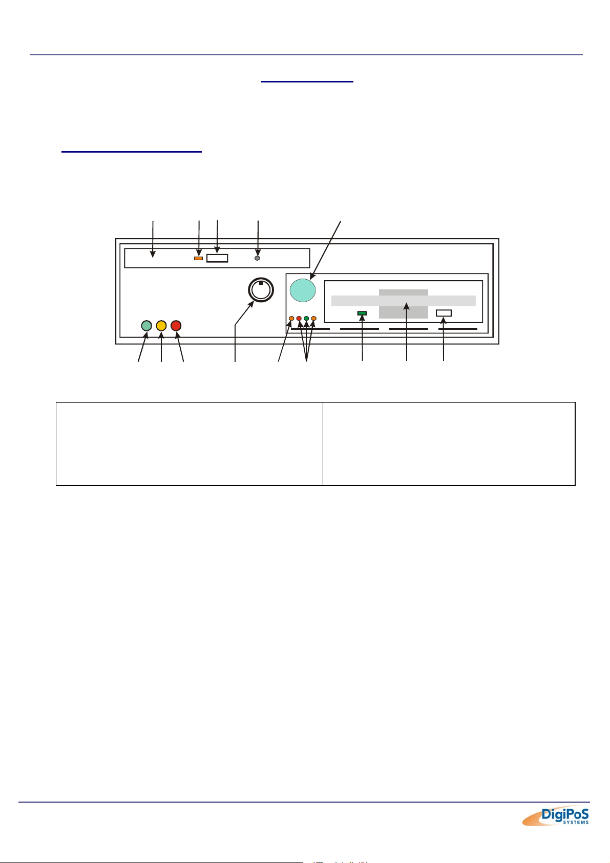
Front Panel Orientation
(Shown with front panel down)
10 11 12 13 14
123 4
5
6 7 8
9
1. LED- Power On Indicator
2. LED- LAN Status Indicator
3. LED- HDD Activity Indicator
4. Front Panel & CD ROM Lock
5. LED- DigiPoS Diagnostics Disk On Chip Active
6. LED- Power Distribution Board Voltages
7. LED- FDD Activity Indicator
8. FDD Drawer
9. FDD Release Button
10. CD ROM (Optional)
11. LED- CD ROM Activity Indicator
12. CD ROM Drawer Open Button
13. CD ROM Manual Draw Open Catch
14. Power On / Off Switch
Note
The diagrams shown here are greatly simplified to enable ease of use and there may be
slight variations between these diagrams and the model you have.
Page 21 of 81
Page 22
DigiPoS Millennium Technical Manual
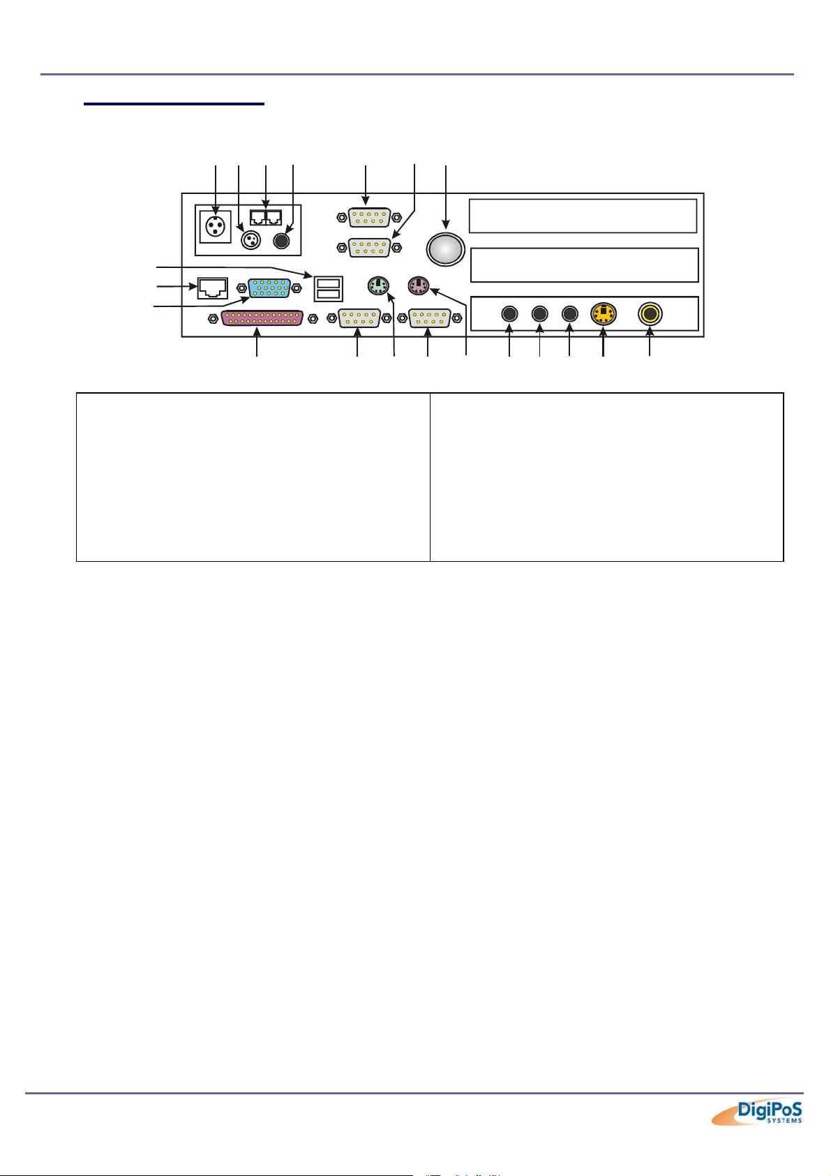
Rear Panel Orientation
12 3 4 5
8
9
10
67
11 12 13 14 15 16 17 18
19 20
1) DC Power Input From PSU
2) 24V Hosiden Connector
3) Cash Drawer Loop Through Connectors
4) 2.5mm Barrel Connector
5) COM1 Port
6) COM2 Port
7) Pulling Knob
8) Two USB Ports
9) LAN Port
10) Parallel Port
11) Parallel Port
12) COM3 Port
13) PS/2 Mouse Port
14) COM4 Port
15) PS/2 Keyboard Port
16) Microphone In Socket
17) Line In Socket
18) Line Out Socket
19) S-Video Out (Optional)
20) TV Out (Optional)
If your DigiPoS Millennium does not have the TV-OUT Module
installed (which is an optional feature), the S-terminal and RCA
TV output will not function.
Page 22 of 81
Page 23
DigiPoS Millennium Technical Manual
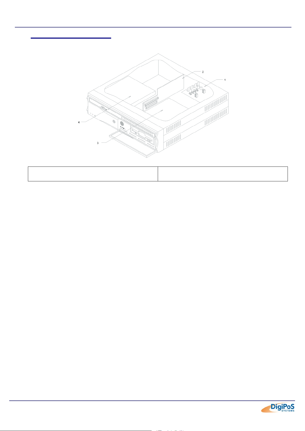
Internal System Orientation
1) Power distribution board
2) Riser Card
3) HDD/FDD sub chassis
4) CD-ROM
Page 23 of 81
Page 24
DigiPoS Millennium Technical Manual
Ope
The Heat Pipe, Air Tunnel & CPU
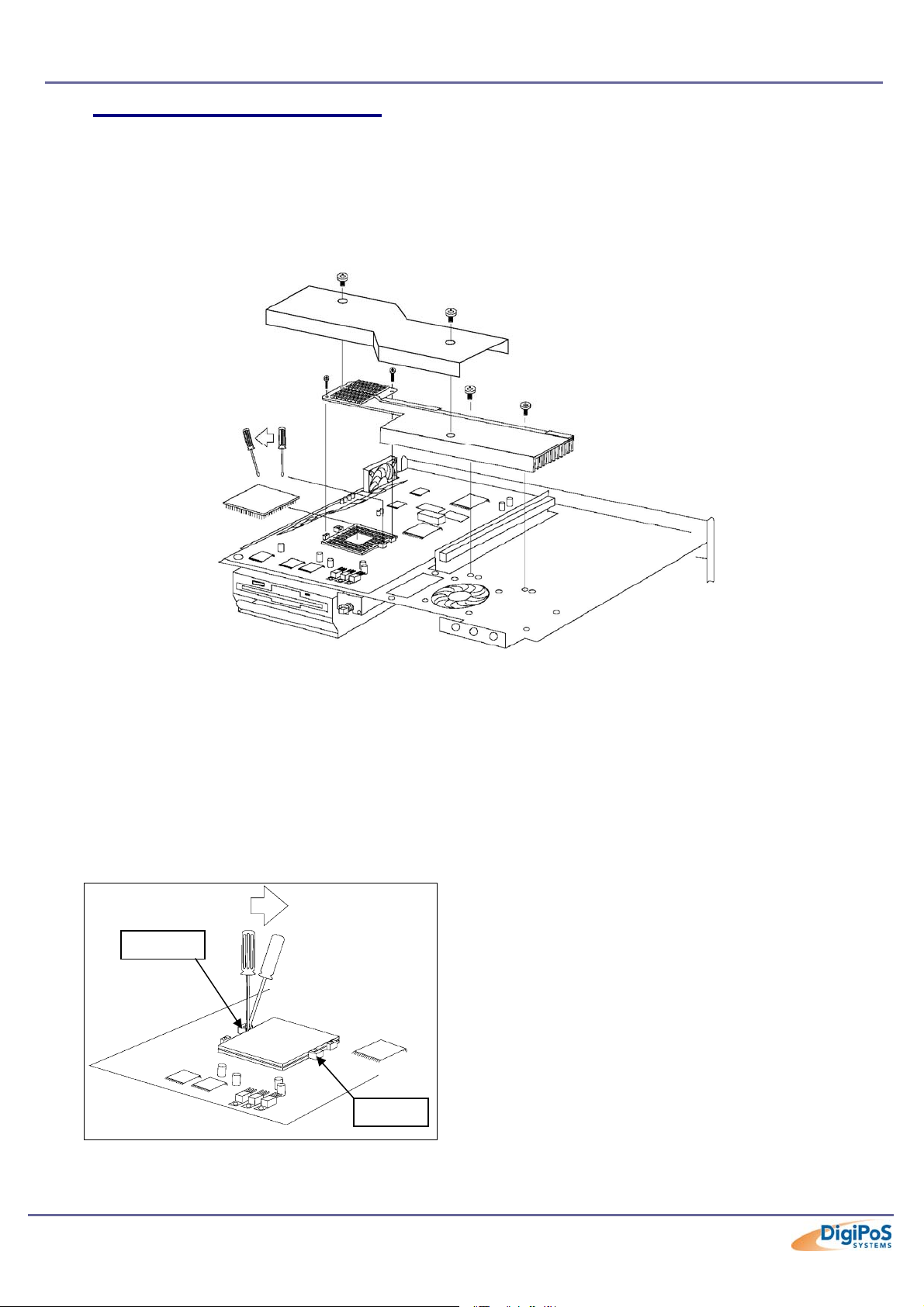
The thermal transfer pad on CPU heat pipe assembly can be easily damaged if the
heat pipe is removed and refitted several times. We therefore recommend that only
DigiPoS Systems or authorized agents for DigiPoS Systems attempt to remove the
heat pipe. Failure to comply with this notice shall void all warranties.
Shown above is an exploded diagram of how access is gained to the CPU via the air
tunnel. It is very important that extreme care is taken when removing this item not to
damage or deform the blue, liquid-cooling assembly in any way. Also please take note of
the screw types and their locations when removing them so that when re-assembly is
undertaken, the correct screws go back into the correct location.
Once the air tunnel assembly has been removed, the CPU should now be visible.
The following steps will take you through how to remove the Socket 370 FC-PGA CPU.
n
Step 1
Use a screwdriver to carefully lever the
processor from the plastic cavity engraved
with “Open” to the “Close” end. This will unlock
your processor and render it free to be
extracted.
The Heat Pipe, Air Tunnel & CPU Cont.
Page 24 of 81
Page 25
DigiPoS Millennium Technical Manual
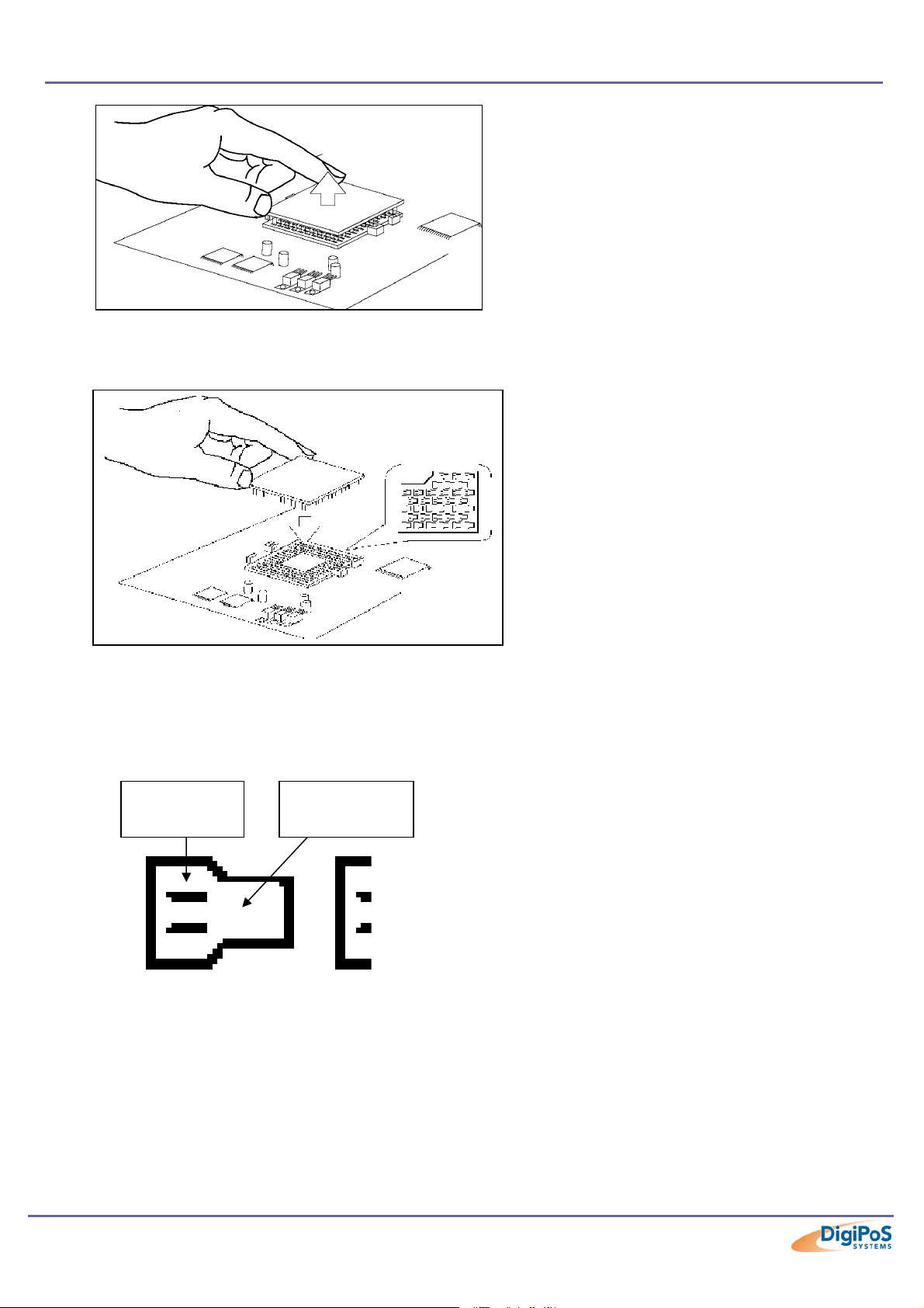
Since there are extra precautions when re-fitting the CPU, the following steps will take you
through how to correctly fit the Socket 370 FC-PGA CPU.
Step 2
After aligning the CPU, make certain the pins on your Pentium processor match up with
the non-gold coated pinhole area as shown on the enlarged detail below.
Goldcoated
Non-gold
coated area
Step 2
The CPU can now be gently removed.
Step 1
Align your CPU by matching the blunt
corner of the processor with the
corresponding distinctive pinhole
arrangement in the socket.
Page 25 of 81
Page 26
DigiPoS Millennium Technical Manual
Ope
The Heat Pipe, Air Tunnel & CPU Cont.
Step 3
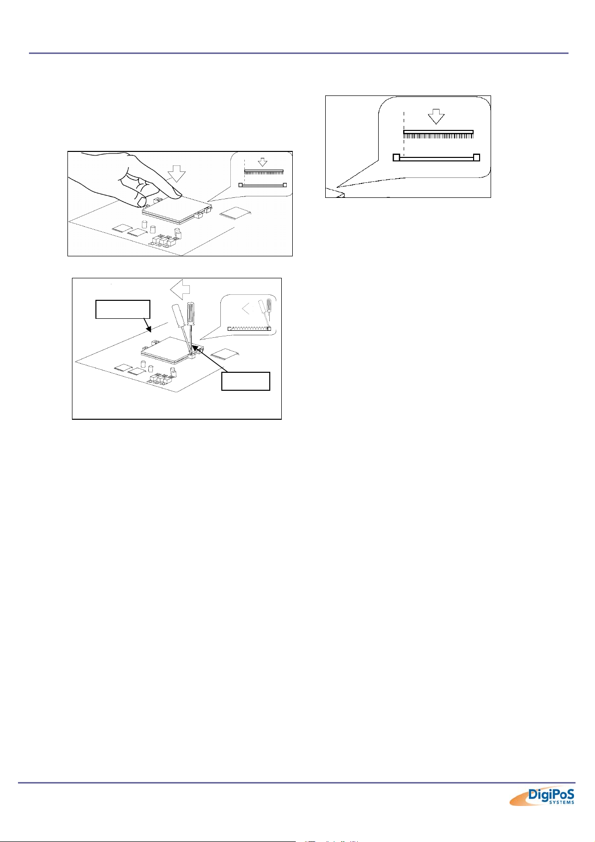
The CPU should be plugged into the socket
firmly, but there is no need to use excessive
force.
n
Step 4
Use a screwdriver to push the processor from
the plastic cavity engraved with “Close” to the
“Open” end. This will push your processor into
the gold-coated pinhole area. You can now
proceed to the heat pipe installation.
Page 26 of 81
Page 27
DigiPoS Millennium Technical Manual
Jumper Settings and Connections
Jumpers
J7
1-2 NORMAL DEFAULT
2-3 CLEAR CMOS
JP1 DISK ON CHIP ADDRESS SELECT
JP1 1-2,7-8 0C800H-0C9FFH
1-2,9-10 0CC00H-0CDFFH
3-4,7-8 0D000H-0D1FFH DEFAULT
3-4,9-10 0D400H-0D5FFH
5-6,7-8 0D800H-0D9FFH
5-6,9-10 0DC00H-0DDFFH
SW2 ON BOARD VGA & PCI
SW2-1 OFF ENABLE ON BOARD VGA DEFAULT
ON DISABLE ON BOARD VGA
SW2-2 OFF ENABLE PCI INTERRUPT DEFAULT
ON DISABLE PCI INTERRUPT
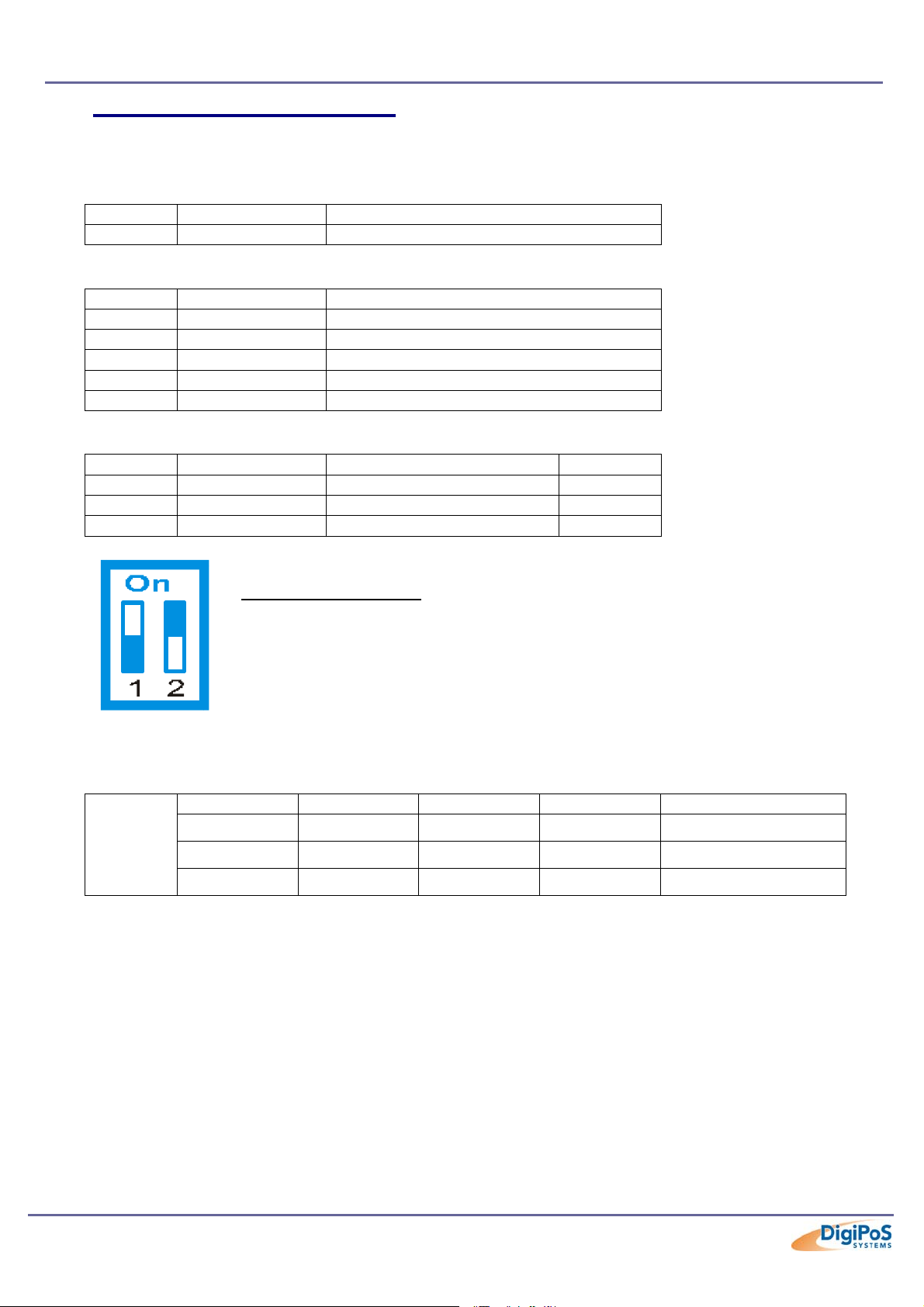
Example of a Switch
The configuration for this switch is:
SW1-1 OFF, SW1-2 ON
CPU Switch Settings
SW1-1 SW1-2 FSB PCI
OFF OFF 133 33.3
SW1
OFF ON 100 33.3 Millennium Default
ON ON 66 33
All other jumpers or switches not mentioned here are either not applicable or have
a reserved use. Do not alter these settings unless you have been instructed to do
so by DigiPoS Systems or an authorised DigiPoS Systems representative. Failure to
comply with this notice shall void all warranties.
Page 27 of 81
Page 28
DigiPoS Millennium Technical Manual
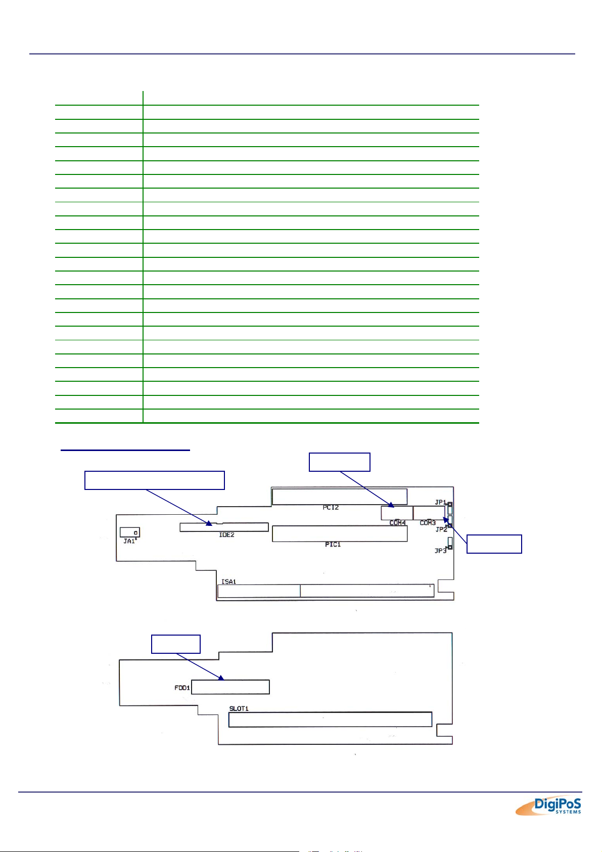
Connections
Name Function
J8 RESET JUMPER
J10 AUDIO & TV-OUT 20 PIN CONNECTOR
VGA1 VGA DSUB 15PIN CONNECTOR
VGA2 VGA 10 PIN (2 rows X 5 pins) CONNECTOR
USB1 USB1 & USB2 CONNECTOR
IDE1 HDD 40 PIN CONNECTOR
COM1 COM1 10 PIN (2 rows x 5 pins) CONNECTOR
COM2 COM2 10 PIN (2 rows x 5 pins) CONNECTOR
LPT1 LPT1 26 PIN (2 rows X 13 pins) CONNECTOR
PS2_MS PS2 6 PIN MOUSE CONNECTOR
PS2_KB PS2 6 PIN KEYBOARD CONNECTOR
KB1 EXT KEYBOARD 1X5 PIN CONNECTOR
PWR1 POWER 8 PIN INPUT CONNECTOR
PWR POWER LED CONNECTOR
LAN LAN LED CONNECTOR
HDD IDE1 LED CONNECTOR
J11 DISK ON CHIP LED CONNECTOR
FAN1 FAN 3 PIN CONNECTOR
FAN2 FAN 3 PIN CONNECTOR
U2 LAN BOOT ROM PLCC 32 PIN SOCKET
U30 DISK ON CHIP DIP 32 PIN SOCKET
U37 LAN RJ45 8 PIN CONNECTOR
LCD1 & LCD2 TV-OUT or TMDS PIGGY BACK BOARD CONNECTOR
Riser Card Orientation
Page 28 of 81
Page 29
DigiPoS Millennium Technical Manual
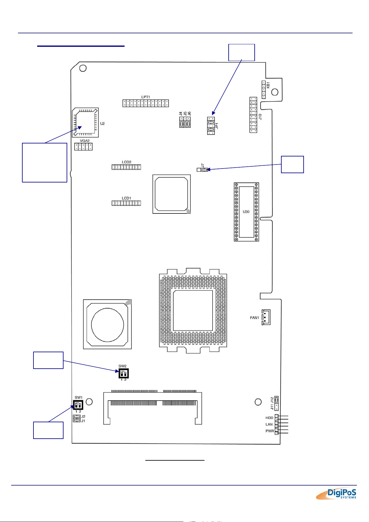
Motherboard Orientation
Network
Boot
Rom
Socket
SW2
SW1
AGP
Graphics
Chip
MEMORY
VIA
Chip
CPU
Component Side
JP1
J7
Page 29 of 81
Page 30
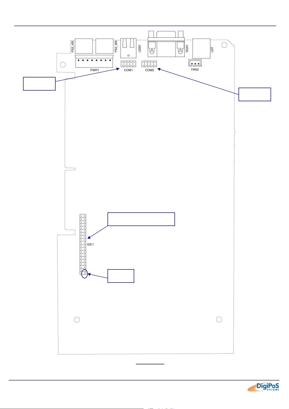
COM 1
DigiPoS Millennium Technical Manual
COM 2
HDD Connector
Pin1
Underside
Page 30 of 81
Page 31
DigiPoS Millennium Technical Manual
I/O Interfaces & Power Connectors
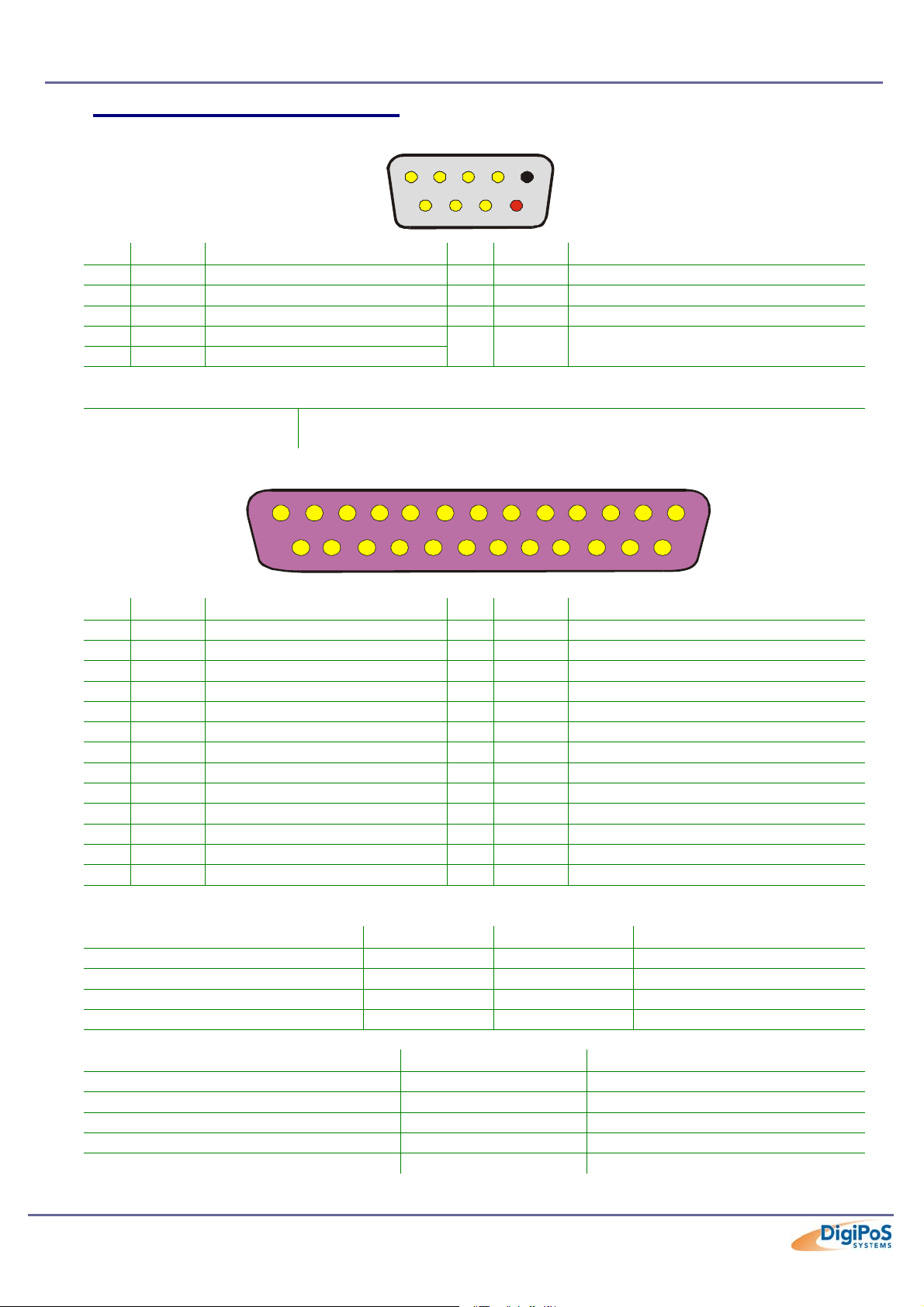
RS232 Standard Serial Ports
123 45
6789
Pin Signal Function Pin Signal Function
1 CD Carrier Detect (IN) 6 DSR Data Set Ready (In)
2 RD Receive Data (IN) 7 RTS Request To Send (OUT)
3 TD Transmit Data (OUT) 8 CTS Clear To Send (IN)
4 DTR Data Terminal Ready (OUT)
5 SG Signal & -VDC Supply ground
9 -
+VDC Supply From Power
Distribution Board
Specifications
Speeds
(In Bits per Second)
75, 110, 134, 150, 300, 600, 1200, 1800, 2400, 4800, 7200, 9600,
14400, 19200, 38400, 57600, 115200 & 128000
Parallel Port
12345678910111213
14
15 16
18 19 20
17
21 22
23
24
25
Pin I / O Function Pin I / O Function
1 Out -Strobe 14 Out -Auto Feed
2 Out +Data Bit 0 15 In -Error
3 Out +Data Bit 1 16 Out -Initialise Printer
4 Out +Data Bit 2 17 Out -Select Input
5 Out +Data Bit 3 18 In Data Bit 0 Return (GND)
6 Out +Data Bit 4 19 In Data Bit 1 Return (GND)
7 Out +Data Bit 5 20 In Data Bit 2 Return (GND)
8 Out +Data Bit 6 21 In Data Bit 3 Return (GND)
9 Out +Data Bit 7 22 In Data Bit 4 Return (GND)
10 In +Acknowledge 23 In Data Bit 5 Return (GND)
11 In +Busy 24 In Data Bit 6 Return (GND)
12 In +Paper End 25 In Data Bit 7 Return (GND)
13 In +Select
Specifications
Parallel Port Type Input Mode Output Mode Comments
SPP (Standard Parallel Port) Nibble Compatible 4-Bit Input, 8-Bit Output.
Bidirectional Byte Compatible 8-Bit I/O
EPP (Enhanced Parallel Port) EPP EPP 8-Bit I/O
ECP (Enhanced Capabilities Port) ECP ECP 8-Bit I/O, Uses DMA
Parallel Port Mode Direction Transfer Rate
Nibble (4-Bit) Input Only 50Kb / Sec
Byte (8-Bit) Input Only 150Kb / Sec
Compatible Output Only 150Kb / Sec
EPP Input / Output 500Kb – 2Mb / Sec
ECP Input / Output 500Kb – 2Mb / Sec
Page 31 of 81
Page 32
DigiPoS Millennium Technical Manual
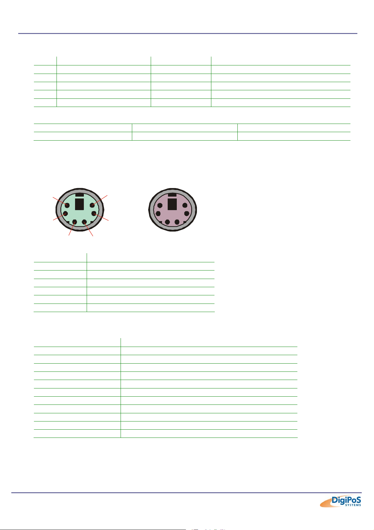
USB Ports
Pin Signal Name Wire Colour Comment
1 VCC Red Cable Power
2 - Data White Data Transfer
3 + Data Green Data Transfer
4 Ground Black Cable Ground
Shell Shield - Drain Wire
USB Data Rates
USB 1.1 Low Speed 1.5Mbits / Sec 0.1875Mbytes / Sec
USB 1.1 High Speed 12Mbits / Sec 1.5Mbytes / Sec
PS / 2 Keyboard & Mouse Ports
Mouse Keyboard
6
43
Pin Signal Name
1 Data from Device
2 Not Connected
3 Ground
4 +5V DC
5 Clock
6 Not Connected
Windows Shortcut Keys
(For a standard 104 key keyboard)
Key Combination Resulting Action
WIN + R Run Dialog Box
WIN + M Minimise All Open Windows
Shift + WIN + M Undo Minimise All Open Windows
WIN + D Minimise All or Undo Minimise All
WIN + F1 Help
WIN + E Start Windows Explorer
WIN + F Find Files or Folders
Ctrl + WIN + F Find Computer on a Network (LAN or WAN)
WIN + Tab Cycle Through Taskbar Buttons
WIN + Break System Properties Dialog Box
WIN + L Log Off Windows
5
12
Page 32 of 81
Page 33
DigiPoS Millennium Technical Manual
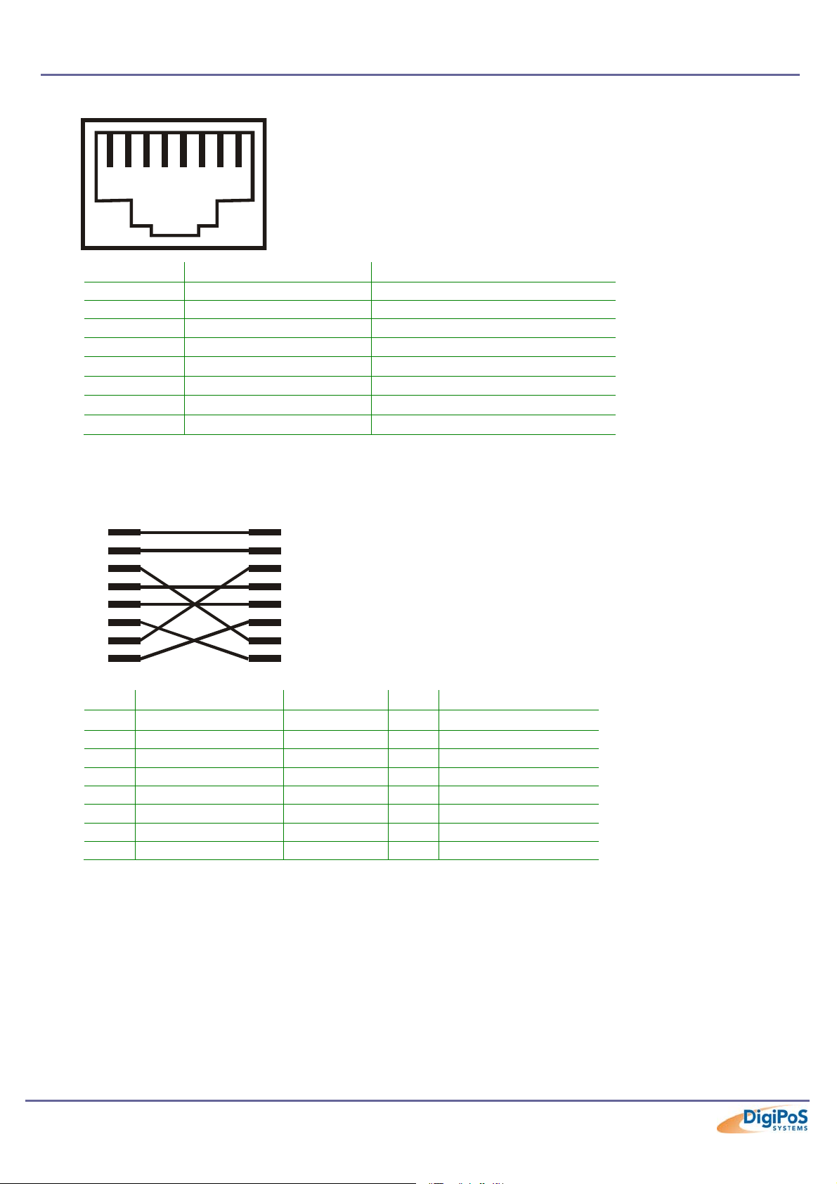
LAN Connector
12345678
Pin Wire Colour Description
1 White / Orange Transmit
2 Orange Transmit
3 White / Green Receive
4 Blue
5 White / Blue
6 Green Receive
7 White / Brown
8 Brown
⊗ = These Pairs are not used with 10BaseT or Fast Ethernet 100BaseTX. These pairs are only required for
100BaseT4 and Gigabit Ethernet 1000BaseTX Standards.
Not Used⊗
Not Used⊗
Not Used⊗
Not Used⊗
Crossover Cable Pin Out
8
234567
1
Pin Wire Colour To Pin Wire Colour
1 White / Orange - 3 White / Green
2 Orange - 6 Green
3 White / Green - 1 White / Orange
4 Blue - 4 Blue
5 White / Blue - 5 White / Blue
6 Green - 2 Orange
7 White / Brown - 7 White / Brown
8 Brown - 8 Brown
Network Distance Limitations
100BaseTx (utilizing standard UTP CAT5 Cable) = 328 Feet (100 Meters)
This distance represents an expected maximum not a guaranteed standard since there
are many external considerations that will limit this distance.
12345678
Page 33 of 81
Page 34
DigiPoS Millennium Technical Manual
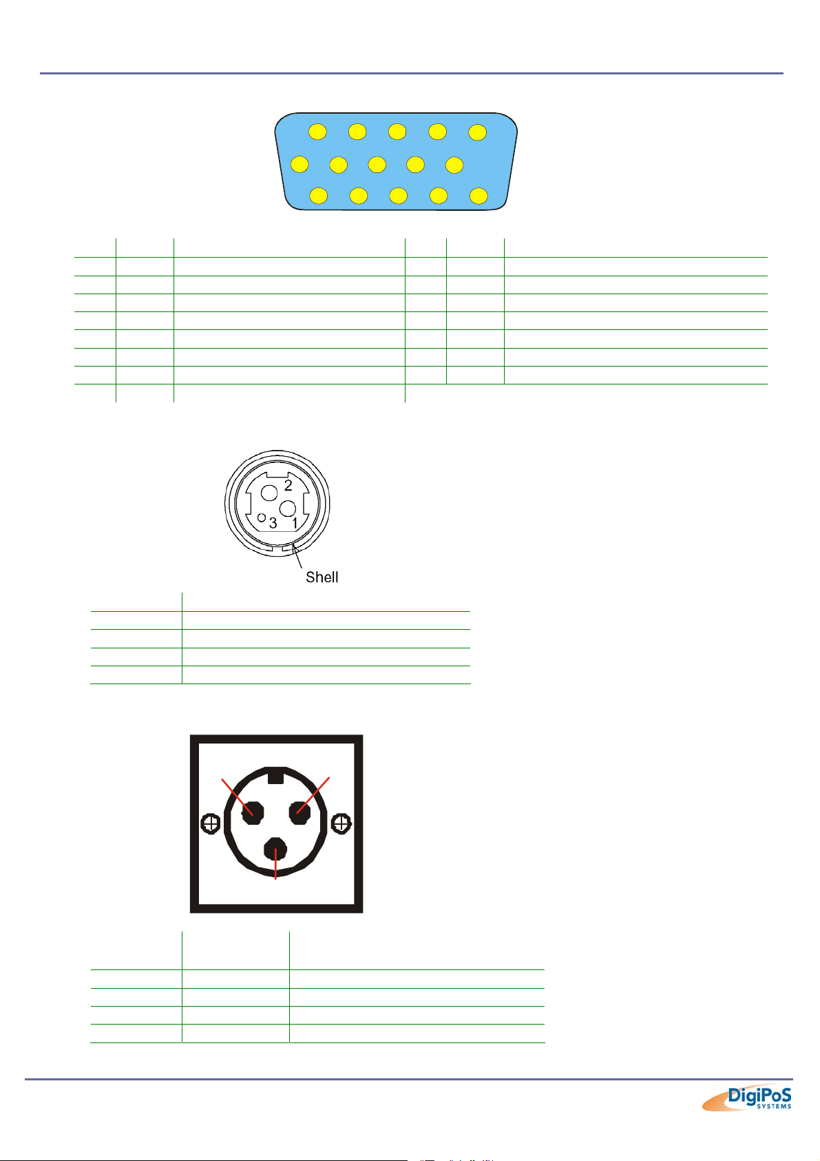
VGA Connector
1234
5
678910
11 12 13 14 15
Pin I / O Function Pin I / O Function
1 Out Red Video 9 - Key (Plugged Hole)
2 Out Green Video 10 - Sync Ground
3 Out Blue Video 11 In Monitor ID 0
4 In Monitor ID 2 12 In Monitor ID 1
5 - TTL Ground (Monitor Self Test) 13 Out Horizontal Sync
6 - Red Analogue Ground 14 Out Vertical Sync
7 - Green Analogue Ground 15 In Monitor ID 3
8 - Blue Analogue Ground
Hosiden Connector
Pin Description
1 +24V DC
2 Ground
3 Not Connected
Shell Frame Ground
Power Supply Connector
1
3
2
Pin Wire
Description
Colour
1 White +24V DC
2 Green Remote Power Supply Switching
3 Black Ground
Shell - Not Connected
Page 34 of 81
Page 35

DigiPoS Millennium Technical Manual
2.5mm Barrel Connector
-Ve
The Voltage for the 2.5mm Barrel is selected via J5 on the Power Distribution board
outlined in the next section.
NOTE
If the 2.5mm barrel is being used to power an LCD, extra caution is to be taken in the
event that the cable becomes loose. If the cable becomes detached, either from the
DigiPoS end or the LCD end, first switch off the monitor using the power button on the
front of the LCD and then re-attach the cable. If this is not carried out correctly, you risk
blowing the fuse or even damaging the DigiPoS if the LCD is left on while trying to reconnect the cable.
+Ve
Page 35 of 81
Page 36
DigiPoS Millennium Technical Manual
Power Distribution on the DigiPoS Millennium
WARNING
Any or all of the serial ports may be configured for 5, 9, 12 or 24 volt on pin 9 of their
respective D-type connector. This can result in damage to peripheral equipment if the
incorrect voltage is selected. For example if a modem is connected to a port configured for
24 volts the modem will almost certainly be destroyed. It is therefore imperative that the
voltage selected is suitable for the device attached. It is also important to remember that
the industry standard connector for a RS232 serial port is a 9 pin D-type plug, and as pin 9
can be powered it is physically possible to short out pin 9 to either pin 5, 8 or the chassis.
This will almost certainly result in serious damage to the motherboard and possibly to the
peripheral as well. If either selecting the wrong voltage or removing the connectors while
the devices are powered damages ANY peripheral device or the DigiPoS, a charge may
be applied by DigiPoS Systems for any repairs necessary.
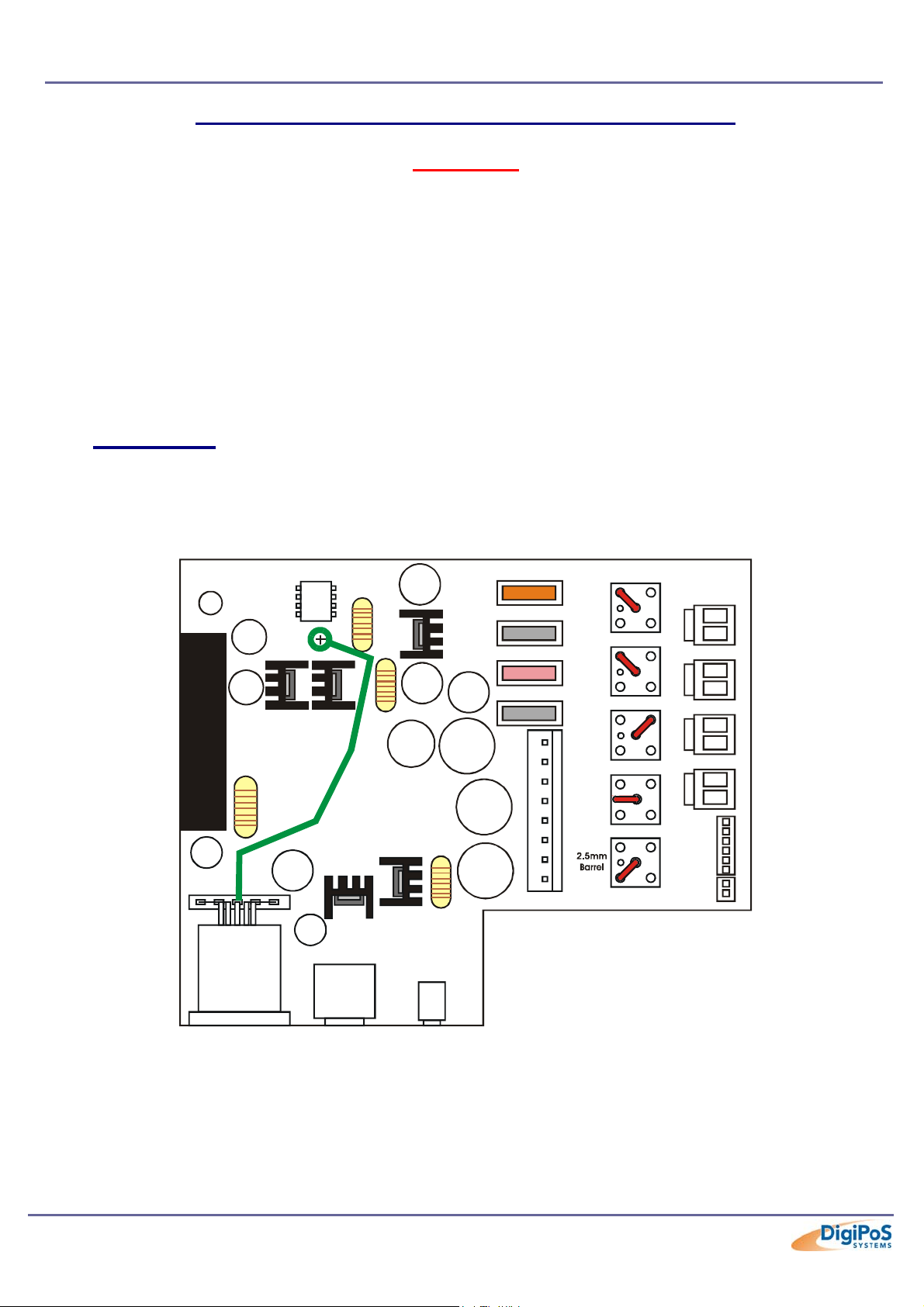
Configuration
The diagram below shows the power distribution board and the jumper arrangement. The
diagram shows an example set-up with the following voltages set: Com1 = 24V, Com2 =
24V, Com3 = 5V, Com4 = Not Set and the 2.5mm Barrel = 12V.
F1 +24V
5A
F2 +9V
2A
F3 +12V
4A
F4 +5V
2A
24
COM 1
12
24
COM 2
12
24
COM 3
12
24
COM 4
12
24
12
Power Distribution Board Layout
5
J1
9
5
J2
9
5
J3
9
5
J4
9
5
J5
9
COM 1
COM 2
COM 3
COM 4
J6
J7
Page 36 of 81
Page 37
DigiPoS Millennium Technical Manual
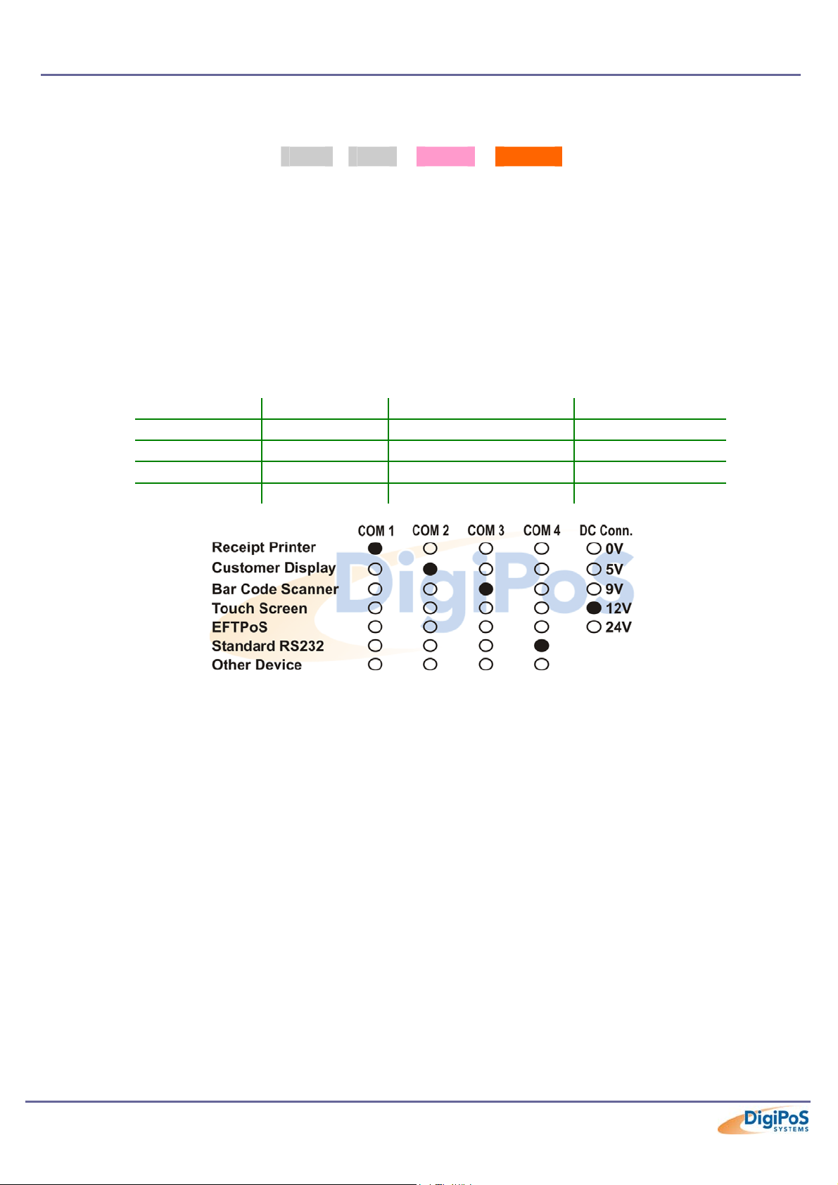
Correct Fuse Ratings
5V
2A 2A 4A 5A
9V
12V
24V
The Fuse ratings must never be exceeded.
If a fuse blows, it is either an indication of a problem with a powered peripheral or that
voltage is drawing too much current. If you have to replace the same fuse more than once
in any 24-hour period, please contact DigiPoS Systems or your DigiPoS Systems
representative. The fuse type is a mini-blade automotive fuse. Please contact you’re
nearest DigiPoS Systems office or representative if you require replacements or spares.
Power Board Configuration
Jumper Port Setting Default Setting
J1 COM1 0, 5, 9, 12, 24, Modem Not set
J2 COM2 0, 5, 9, 12, 24, Modem Not set
J3 COM3 0, 5, 9, 12, 24, Modem Not set
J4 COM4 0, 5, 9, 12, 24, Modem Not set
J5 Barrel 0, 5, 9, 12, 24, Modem Not set
A typical configuration sticker giving details on what voltage has been set with regard to
which port. This sticker can usually be found on the inside of the front flap. Please note
the Modem position (standard RS232) if required.
Application
Unless specified at time of order, the DigiPoS will be shipped with the default jumper
settings of 0 Volts. If you wish to have a particular set-up, including the Modem option,
then please contact your PC-PoS representative.
The modem option will permit the connection of an external modem to the DigiPoS and
allows the use of the ring indicator (RI) signal. The Ring Indicator is the signal the modem
gives to the DigiPoS to tell the software that someone is trying to connect to it. The RI
signal is normally found on pin 9 of the d-type connectors and as this is the pin that is
used to supply power to the peripherals it is necessary to replace the internal cable
connection to the selected port. For example if a modem option is selected for COM port
3, then the powered cable assembly would be removed for COM port 3 and be replaced
with a non powered version. This would not affect the other 3 ports, they would remain
powered or as per requested configuration.
Page 37 of 81
Page 38
DigiPoS Millennium Technical Manual
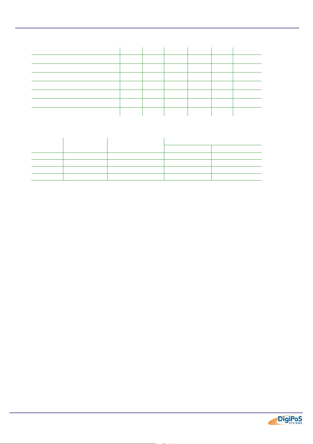
Typical Voltage Requirements
Device 0 5 9 12 24 Modem
Epson PoS Printer
Epson PoS Display
MSR-512 swipe reader
MS-9540 Voyager
DigiPoS Customer Display
LCD Monitor
External Modem
Continuous and Peak Current Capacity
Voltage
5 5.01 4.85 – 5.15 2 3
9 9.02 8.82 – 9.18 0.8 1.5
12 11.88 11.40 – 12.60 3 4
24 24.00 23.52 – 24.48 3 5
Continuous current is the current drawn by a device during normal operation. An example
of continuous current is a receipt printer printing a receipt or docket. Peak current is
defined as the maximum current drawn for a finite period of time. An example of peak
current is when a printer is initially powered on.
Under no circumstances is the peak current to be exceeded or drawn for an
extended period of time. Overloading of the voltages is not recommended and can
render the DigiPoS inoperable or may even permanently damage circuitry within the
DigiPoS. Overloading of any of the Voltages will void all warranties, either on the
DigiPoS or any connected peripherals. If any permanent damage occurs, charges
will apply for any repairs necessary.
Actual
(Default)
- - - - Y -
- - - - Y -
- Y - - - -
- Y - - - -
- - - - Y -
- - - Y - -
- N N N N Y
VMin – Vmax
(Open Circuit)
Current (A)
Continuous Peak
Page 38 of 81
Page 39

DigiPoS Millennium Technical Manual
Onboard Diagnostics for the DigiPoS Millennium
Diagnostic Overview
The DigiPoS Millennium has built onto the motherboard an area of memory specifically for
diagnostic purposes. This memory area and the program stored in it have been designed
so that system tests can be run without interfering in any way with the operating system or
user applications. The diagnostic tests are designed to cope with the majority of
configurations. To access the diagnostics utility and run the tests it is necessary to follow
the procedure laid out below.
Diagnostic Procedure
1. Close down any applications that are running within your operating system and
double click the DigiPoS Diagnostics Icon. The program will shut down software
that is running and then re-starts the system automatically.
2. When the DigiPoS restarts, the orange diagnostic LED, the LED at the left hand
end of the group of four small LED’s below the power switch, should illuminate
to indicate that the DigiPoS is in diagnostic mode.
3. After the initial BIOS screens have cleared a splash screen should be displayed,
this will clear after a second or two.
4. The main diagnostic screen will now appear and the system will start searching
for connected serial devices. When the search has finished a menu will appear
below the logo and show the serial devices found, as per the diagram below.
Check that the devices found match the devices attached and that the serial
parameters match those defined for the peripherals.
5. Exercise each of the test procedures as described in the following sections.
6. After each test has been completed exit the diagnostic program using the
appropriate menu selection and the DigiPoS will automatically re-boot back into
your operating system.
7. The results of the diagnostic tests can be found in a file called “DIAGRSLT.TXT”
stored in a drive called “Diagnostics” which can be accessed by explorer or my
computer.
An Example of a Diagnostic Test Screen
Page 39 of 81
Page 40
DigiPoS Millennium Technical Manual
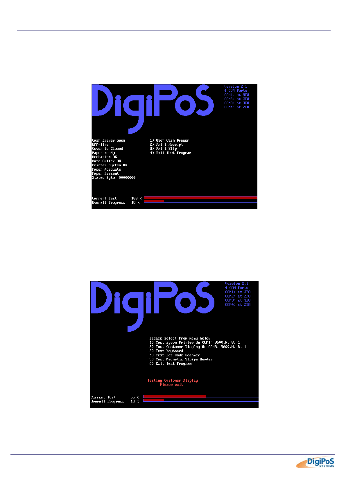
Printer Test
Please note that the Printer test will only work with printers that are Epson ESC/PoS
compliant. The serial scanning software will not reliably detect printers that are not
ESC/PoS compliant and therefore the tests cannot be relied upon.
An Example of a Printer Test
Customer Display Test
Please note that the Customer Display test will only work with displays that are Epson
ESC/PoS compliant, these include all of the Epson displays, the DigiPoS CD-5220 and
the DigiPoS WD-202 (when set up for ESC/PoS emulation). Start the test by pressing the
numbered key next to the menu entry; this will either be menu item 1 or menu item 2.
An Example of a Customer Display Test
Page 40 of 81
Page 41
DigiPoS Millennium Technical Manual
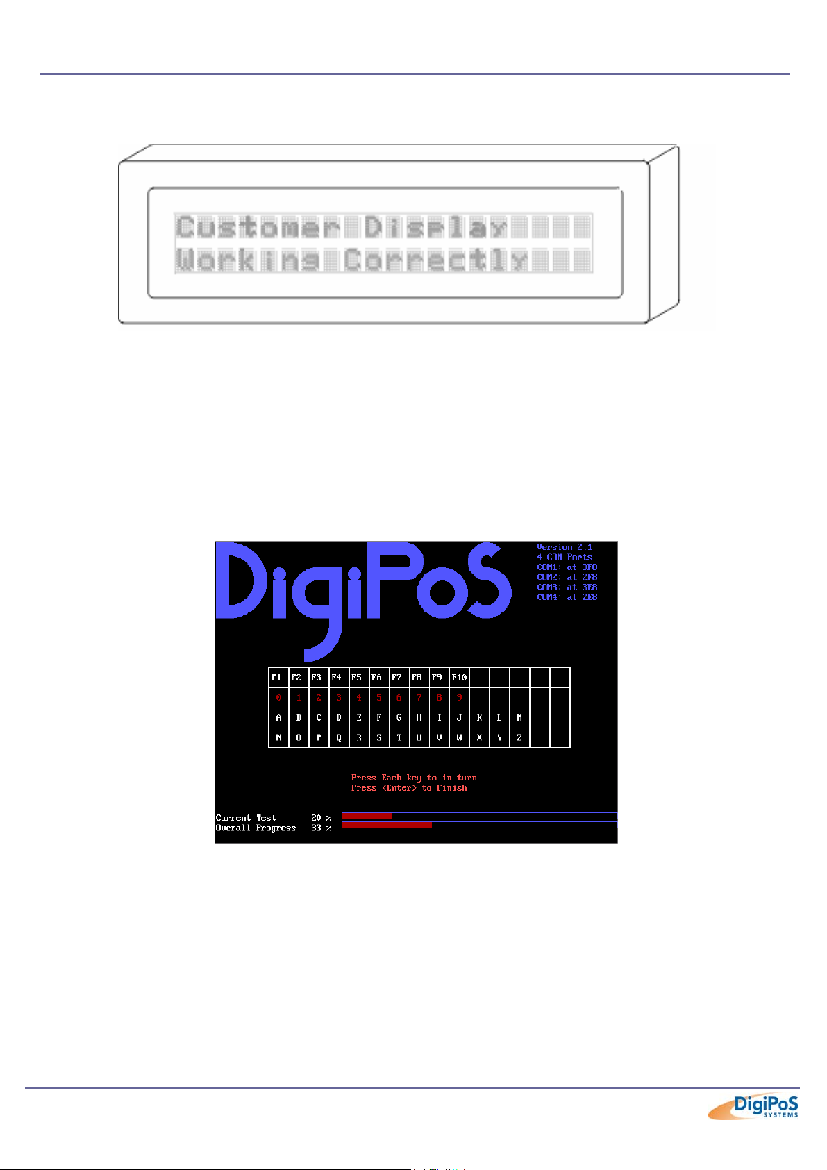
The display should now start to perform a variety of tests culminating with the following
picture.
An Example of a Customer Display
If this picture fails to appear then there is probably something wrong with the display and
should be investigated further by a qualified technician.
Keyboard Test
Due to the almost infinite variations of keyboard layout and key code assignment this
facility can only perform the most basic of tests. The test only allows standard keys, i.e. 09 a-z and F1-F10 to be tested.
An Example of a Keyboard Test
On any given PoS keyboard these keys my or may not be present and even if they are
present they may be labelled as stock items or type of transaction, for example the key
producing the letter “a” may be labelled as “Cheque”. The result of this is that pressing any
key on the keyboard may well produce unexpected, but not necessarily incorrect results.
Pressing any key 3 times terminates this test.
Page 41 of 81
Page 42
DigiPoS Millennium Technical Manual
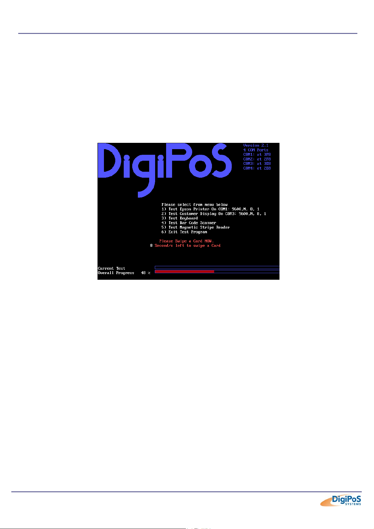
Magnetic Card Test
The diagnostic software is unable to detect the presence or absence of a magnetic card
reader due to the fact that the majority of card readers only transmit data and do not
receive data. Because of this the test menu will always show a magnetic card reader test
even if there is no reader attached. To test a card reader, select the appropriate menu
entry and pass a card through the reader. If the reader is working then the contents of the
data tracks will be displayed on the screen along with a question asking if the displayed
data is correct. The data displayed should be the same as that embossed or printed on
the card. Please note that this test only works with keyboard wedge devices and not
serial.
An Example of an MSR Test
The majority of cards will store more data than is visible on the card, this is normal and as
long as the display includes the information on the card then it is relatively safe to assume
that the card reader is ok. If the card fails to read then try another card or a card from a
different supplier. If no data has been received after 10 seconds then the menu will revert
to the main test menu. DO NOT swipe cards outside of the magnetic card test. Swiping
cards outside of this area will produce unpredictable results.
Page 42 of 81
Page 43
DigiPoS Millennium Technical Manual
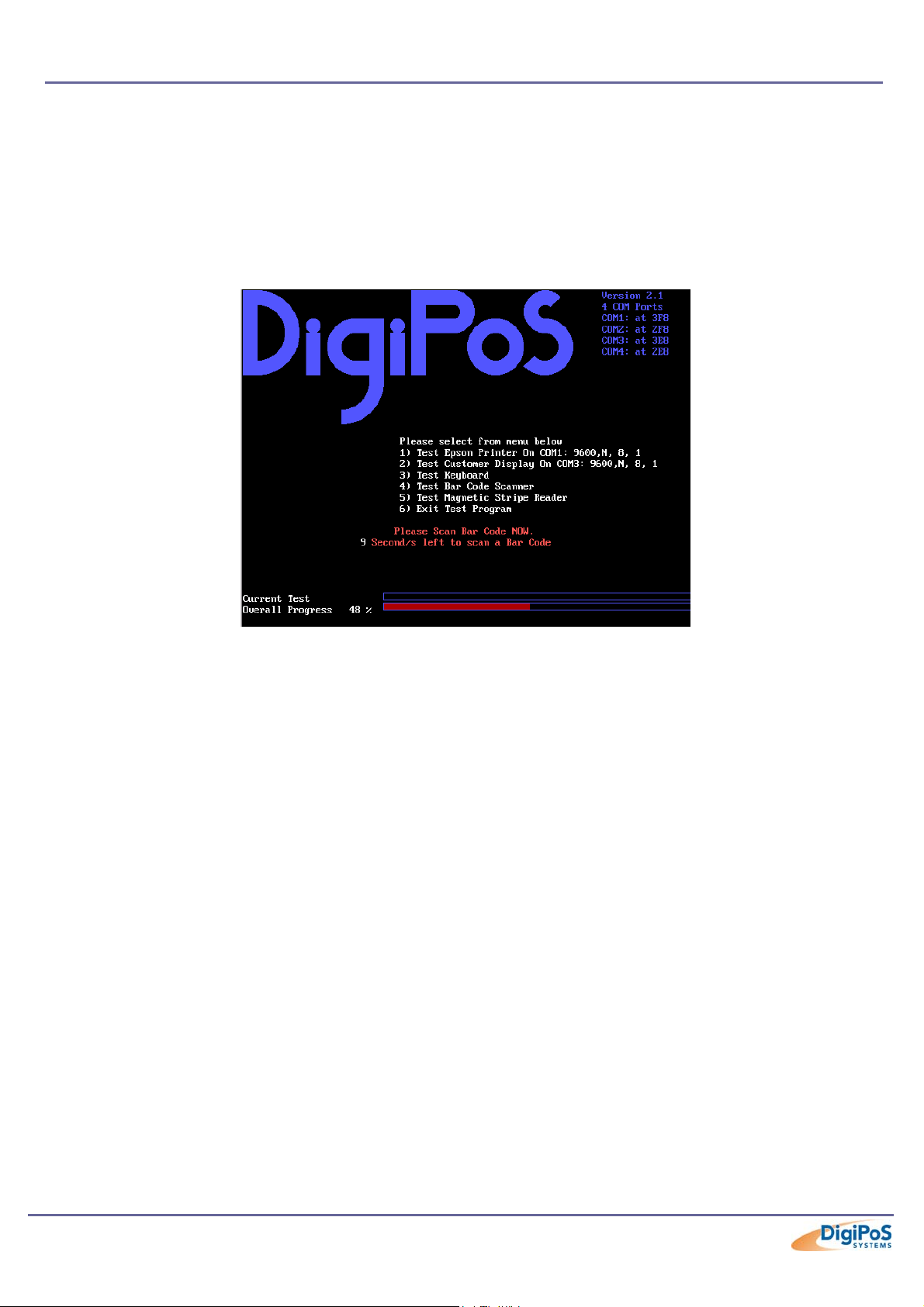
Bar Code Scanner Test
The diagnostic software is unable to detect the presence or absence of a bar code
scanner due to the fact that the majority of bar code scanners only transmit data and do
not receive data. Because of this the test menu will always show a bar code scanner test
even if there is no reader attached. To test a bar code scanner select the appropriate
entry in the main test menu and within 10 seconds scan a bar code. Please note that this
test only works with key board wedge scanners and will not work with serial scanners.
An Example of a Bar Code Test
Page 43 of 81
Page 44

DigiPoS Millennium Technical Manual
BIOS Set-up Overview
The DigiPoS Retail System contains its own permanently programmed SETUP routine,
which allows it to recognize and utilize the system's hardware. For example, one can set
the system to identify hard disk and floppy disk drive capacity, the type of video being
used, and the amount of memory installed. The BIOS (BASIC Input / Output System) will
read this information each time the system boots up.
As setting up the BIOS can be complicated, PC-PoS advises that if any changes to the
BIOS are to be made, only competent qualified computer technicians undertake them.
There are settings within the BIOS that are operating system dependant and have been
set up in accordance to your systems configuration. Altering any of these settings is not
advised under any circumstances as any one setting incorrectly set can drastically alter
the performance of your DigiPoS and could invalidate the warranty.
The following screenshots are a guide through the CMOS set-up utility for the DigiPoS
Millennium. If you need help at any time during this process, press F1 and a small window
will pop up describing the appropriate keys to use and the possible selections for the
highlighted item. To exit the help window press <Esc> or F1.
Please note that the default settings, (regardless of operating system installation which will
be covered later in this section) are shown in BOLD where appropriate.
Page 44 of 81
Page 45

Main BIOS Screen
DigiPoS Millennium Technical Manual
Phoenix – AwardBIOS CMOS Setup Utility
fStandard CMOS Features
fAdvanced BIOS Features
fAdvanced Chipset Features
fIntegrated Peripherals
fPower Management Setup
fPnP/PCI Configuration
fPC Health Status
Esc : Quit Ç È Æ Å : Select Item
F10 : Save & Exit Setup
Time, Date, Hard Disk Type..
fFrequency/Voltage Control
Load Fail-Safe Defaults
Load Optimized Defaults
Set Supervisor Password
Set User Password
Save & Exit Setup
Exit Without Saving
Details
Standard CMOS Features Frequency/Voltage Control
Standard settings like date, time, HDD, FDD etc. Advanced Settings
Advanced CMOS Features Load Fail-Safe Defaults
Advanced settings
Advanced Chipset Features
Advanced settings for the VIA chipset
Loads the Fail Safe default settings that were
programmed in at time of manufacture (Not Generally
Used as the settings are not OS specific and are only to
be used as a last resort)
Integrated Peripherals Load Optimized Defaults
Settings for the onboard devices
Power Management Setup
Controls what devices remain active when a
computer has been left on with no activity for a
set period of time.
PnP/PCI Configurations
Allows you to set IRQ’s to a specific configuration
such as Plug and Play or Legacy ISA.
Loads the optimised default settings that were
programmed in at time of manufacture (Not Generally
Used as the settings are not OS specific and are only to
be used as a last resort)
Set Supervisor Password
Allows for the option of a password to be set so that a
user is prompted for a password when the computer is
switched on or rebooted
PC Health Status Set User Password
Gives current voltage and temperature
measurements inside the DigiPoS
Saves the changes you have made.
Exits the BIOS without saving any changes.
As above with the exception that access is restricted to
some of the BIOS settings.
Save & Exit Setup
Exit Without Saving
Page 45 of 81
Page 46

DigiPoS Millennium Technical Manual
Standard CMOS Features
Phoenix – AwardBIOS CMOS Setup Utility
Standard CMOS Features
Date (mm:dd:yy) : Sun, Apr 28 2002
Time (hh:mm:ss) : 13 : 42 : 39
fIDE Primary Master [ST320410A]
fIDE Primary Slave [None]
fIDE Secondary Master [QSI CD-ROM SCR-2421]
Menu Level f
Change the day, Month,
year and century
Item Help
fIDE Secondary Slave [NONE]
Drive A [1.44M, 3.5 in.]
Drive B [None]
Video [EGA / VGA]
Halt On [All, But Keyboard]
Select Display Device [CRT]
Base Memory 640K
Extended Memory 113664K
Total Memory 114688K
Ç È Æ Å : Move +/-/PU/PD: Value F10 : Save ESC : Exit F1 : General Help
F5 : Previous Values F6: Fail-Safe Defaults F7 : Optimised Defaults
General Details
Feature Options Description
System Time HH:MM:SS Set the system time.
System Date MM/DD/YYYY Set the system date.
360 kB, 5 ¼"
Diskette 1
Diskette 2
1.2 MB, 5 ¼"
720 kB, 3 ½"
1.44/1.25 MB, 3 ½"
2.88 MB, 3 ½"
Not installed
Select the type of floppy-disk drive installed in your
system.
1.25 MB is a Japanese media format that requires a
3½" 3- Mode Diskette drive.
Disabled
EGA/VGA
Video
CGA 40
CGA 80
Select EGA/VGA by default or Mono Only if you are
using a Mono Monitor
Mono
All Errors = The system will halt on any error
No Errors = The system will halt when there are no
errors.
All, But Keyboard = The system will halt on any
error except a keyboard error
All, But Diskette = The system will halt on any error
except a diskette error
Halt On
All Errors
No Errors
All, But Keyboard
All, But Diskette
All, But Disk/Key
All, But Disk/Key = The system will halt on any error
except a diskette error or a Keyboard error
Page 46 of 81
Page 47

DigiPoS Millennium Technical Manual
General Details Cont.
Feature Options Description
Auto
CRT
Select Display Device
System Memory N/A
Extended Memory N/A
Total Memory N/A
LCD
CRT+LCD
TV
CRT+TV
Auto = Auto detects Display Type
CRT = Cathode Ray Tube (Default Setting)
LCD = Liquid Crystal Display
CRT+LCD = Dual Output
TV = Output to a Television (Optional)
CRT+TV = Dual Output (Optional)
Displays amount of conventional memory detected
during boot up.
Displays the amount of extended memory detected
during boot up.
Displays the amount of memory detected during
boot up.
Page 47 of 81
Page 48
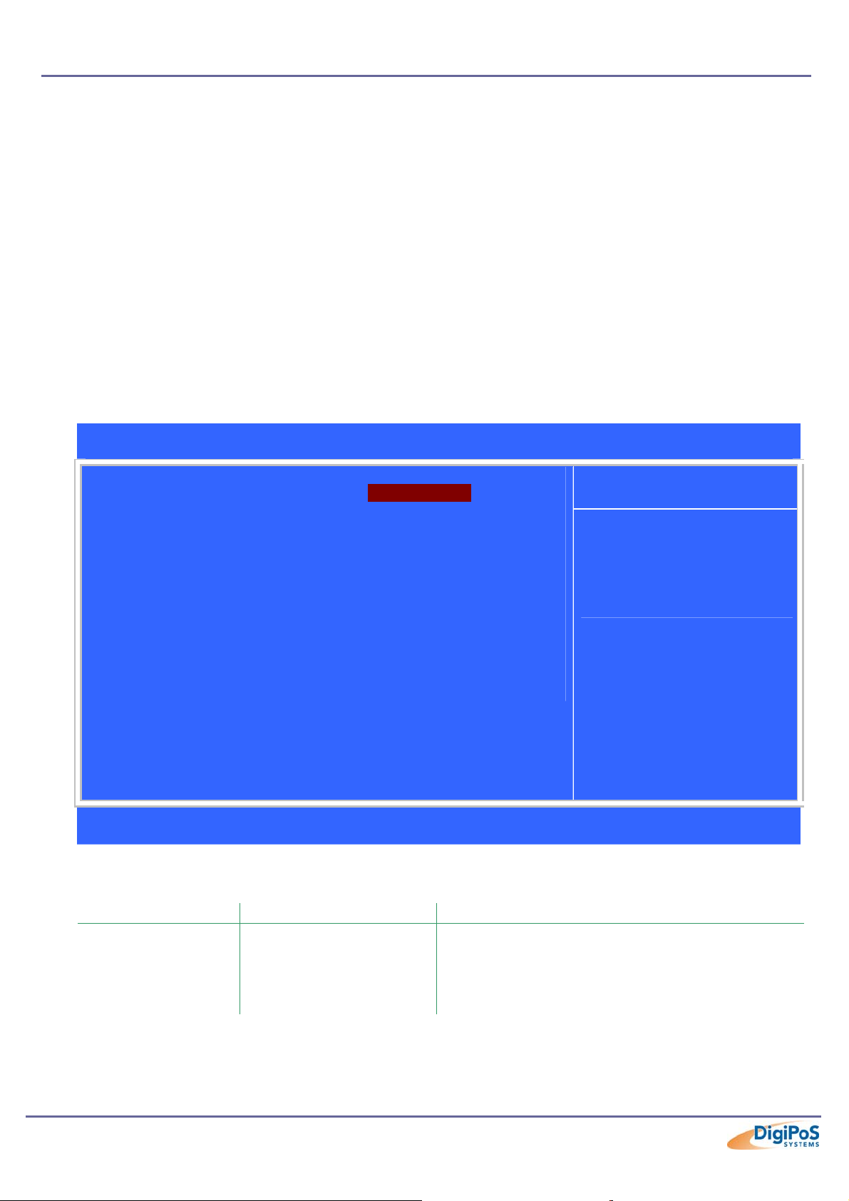
DigiPoS Millennium Technical Manual
IDE Options Sub Menus
The Master and Slave sub-menus accessed from the Main Menu control these types of
devices:
o Hard disk drives
o Removable-disk drives such as Zip drives
o CD-ROM drives
The DigiPoS BIOS supports up to two IDE disk adapters, called primary and secondary
adapters. Each adapter supports one master drive and one optional slave drive in these
possible combinations:
o 1 Master (3.5” HDD without CD ROM)
o 1 Master, 1 Slave (3.5” HDD and CD ROM)
o 2 Masters (2 x 2.5” HDD)
o 2 Masters, 1 Slave (2 x 2.5” HDD and CD ROM)
If you need to change your drive settings, selecting one of the Master or Slave drives on
the Main Menu displays a sub-menu like this:
Phoenix – AwardBIOS CMOS Setup Utility
IDE Primary Master
IDE HDD Auto-Detection [Press Enter]
IDE Primary Master [Auto]
Access Mode [Auto]
Capacity 20021 MB
Cylinder 38792
Head 16
Precomp 0
Landing Zone 38791
Sector 63
Ç È Æ Å : Move +/-/PU/PD: Value F10 : Save ESC : Exit F1 : General Help
F5 : Previous Values F6: Fail-Safe Defaults F7 : Optimised Defaults
Menu Level ff
To auto-detect the
HDD’s size, head…. On
this channel
Item Help
Details
Feature Options Description
None = Either NO drive is installed or you can
IDE Primary Master/
Slave/ Secondary
Master/ Slave
None
Auto
Manual
disable any drive that may be installed.
Manual = Non-Functional in this BIOS.
Auto = Auto detect. The drive itself supplies the
correct information (Default)
Page 48 of 81
Page 49

DigiPoS Millennium Technical Manual
Details Cont.
Feature Options Description
CHS
Access Mode
Capacity N/A HDD size in Mb
Cylinder 1 to 65,536 Number of cylinders.
Head 1 to 16 Number of read/write heads.
Precomp
Landing Zone N/A
Sector N/A Number of Sectors per track
LBA
Large
Auto
1 to 2048
None
CHS = Cylinder, Head, Sector
LBA = Logical Block Addressing
Large = Large Disk Access Mode
Auto = Auto Detect correct mode for HDD in use.
Number of the cylinder at which to change the
write timing.
2048 Number of the cylinder specified as the
landing zone for the read/write heads
Page 49 of 81
Page 50

DigiPoS Millennium Technical Manual
w
Advanced BIOS Features
Phoenix – AwardBIOS CMOS Setup Utility
Advanced CMOS Features
Virus Warning [Disabled]
CPU Internal Cache [Enabled]
External Cache [Enabled]
CPU L2 Cache ECC Checking [Enabled]
Quick Power On Self Test [Disabled]
First Boot Device [Floppy]
Second Boot Device [CDROM]
Third Boot Device [HDD-1]
Boot Other Device [Enabled]
Swap Floppy Drive [Disabled]
Boot Up Floppy Seek [Enabled]
Boot up NumLock Status [Enabled]
Gate A20 Option [Fast]
Typematic Rate Setting [Disabled]
xTypematic Rate (Chars/Sec) 6
xTypematic Delay (Msec) 250
Security Option [Setup]
OS Select For DRAM > 64Mb [Non-OS2]
Video BIOS Shadow [Enabled]
C8000-CBFFF Shadow [Disabled]
CC000-CFFFF Shadow [Disabled]
D0000-D3FFF Shadow [Disabled]
D4000-D7FFF Shadow [Disabled]
D8000-DBFFF Shadow [Disabled]
DC000-DFFFF Shadow [Disabled]
Small Logo(EPA) Show [Disabled]
Item Help
Menu Level f
Allows the system to
skip certain tests
while booting. This
ill decrease the time
needed to boot the
system.
Ç È Æ Å : Move +/-/PU/PD: Value F10 : Save ESC : Exit F1 : General Help
F5 : Previous Values F6: Fail-Safe Defaults F7 : Optimised Defaults
Details
Feature Options Description
This feature warns the user if a program, such as a
virus, tries to write to the boot sector of the hard drive.
Please note that this does not protect the entire hard
drive and if the drive is ever re-formatted or repartitioned, a warning can be triggered.
This disables the CPU’s internal cache memory. This
can be useful when testing memory installed in the
computer.
Enables or Disables the motherboards Cache Memory.
This can be useful for testing if a problem is suspected
with the CPU Cache memory.
Error Correction Checking of the L2 CPU Cache Memory
Allows the system to skip certain tests while booting.
This will decrease the time needed to boot the system.
This is not recommended for system stability
Virus Warning
CPU Internal Cache
External Cache
CPU L2 Cache ECC Checking
Quick Power On Self Test
Enabled
Disabled
Enabled
Disabled
Enabled
Disabled
Enabled
Disabled
Enabled
Disabled
Page 50 of 81
Page 51

DigiPoS Millennium Technical Manual
Details Cont.
Feature Options Description
Floppy
LS120
Determines which order the computer tries to boot into
an operating system from a certain device.
Default is as follows:
First Boot Device: Floppy
Second Boot Device: CDROM
Third Boot Device: HDD-1
For devices installed that can act as a bootable device.
Only valid in systems with two floppy drives. This
allows the system to swap drive A to Drive B and vice
versa.
This tests to see if the floppy drive has 40 or 80 tracks.
40 Track drives are only 360Kb where 80 track drives
can be 720Kb, 1.2Mb or 1.44Mb, which is the standard
today. Because only the 1.44Mb is used in the DigiPoS,
this function can be disabled to save time during the
POST (Power On Self Test).
Sets the number lock to on or off after boot up.
Gate A20 refers to the way the system addresses
memory above 1Mb (Extended Memory). When this is
set to fast, the VIA chipset controls Gate A20. When
set to Normal, a pin in the keyboard controller controls
Gate A20. Setting Gate A20 to Fast improves system
performance.
When enabled, you can specify the parameters for the
typematic settings. Usually this is disabled which
renders the next two settings irrelevant.
This is the rate at which a character is repeated when
you hold down a key on the keyboard.
When the typematic rate setting is enabled, you can
use this setting to determine how long a delay will
occur before the character is repeated at the typematic
rate.
If the password option is selected, you can use this
setting to determine if the password is required every
time the computer boots or only when some one tries to
gain access to the BIOS settings.
First Boot Device
Second Boot Device
Third Boot Device
Boot Other Device
Swap Floppy Drive
Boot Up Floppy Seek
Boot Up NumLock Status
Gate A20 Option
Typematic Rate Setting
Typematic Rate (Chars/Sec)
Typematic Delay (Msec)
Security Option
HDD-0
SCSI
CDROM
HDD-1
HDD-2
HDD-3
ZIP100
LAN
Disabled
Enabled
Disabled
Enabled
Disabled
Enabled
Disabled
Enabled
Disabled
Fast
Normal
Enabled
Disabled
6
8
10
12
15
20
24
30
250
500
750
1000
Setup
System
Page 51 of 81
Page 52

DigiPoS Millennium Technical Manual
Details Cont.
Feature Options Description
OS Select for DRAM > 64Mb
Video BIOS Shadow
C8000-CBFFF Shadow
CC000-CFFFF Shadow
D0000-D3FFF Shadow
D4000-D7FFF Shadow
D8000-DBFFF Shadow
DC000-DFFFF Shadow
Small Logo(EPA) Show
Non-OS2
OS2
Enabled
Disabled
Disabled
Disabled
Disabled
Disabled
Disabled
Enabled
Disabled
This allows you to access memory over 64MB in
OS/2.
This enables you to move programs from 16 bit
ROM to 32 bit RAM since RAM is faster than
ROM. This can speed up video and other
operations significantly but only in DOS
applications since windows 9x, 2K & Xp then load
32 bit replacement programs into the main
memory.
Displays the Yellow EPA Logo during boot up.
Page 52 of 81
Page 53

DigiPoS Millennium Technical Manual
Advanced Chipset Features
Phoenix – AwardBIOS CMOS Setup Utility
Advanced Chipset Features
DRAM Clock [Host CLK]
SDRAM Cycle Length [3]
Bank Interleave [Disabled]
Memory Hole [Disabled]
P2C/C2P Concurrency [Enabled]
System BIOS Cacheable [Disabled]
Video RAM Cacheable [Enabled]
Frame Buffer Size [8M]
AGP Aperture Size [8M]
AGP-4X Mode [Enabled]
AGP Driving Control [Auto]
XAGP Driving Value DA
Disk on Chip Control [Disabled]
Onboard LAN Control [Enabled]
Power Supply Type [AT]
OnChip USB [Enabled]
USB Keyboard Support [Disabled]
OnChip Sound [Auto]
CPU to PCI Write Buffer [Enabled]
PCI Dynamic Bursting [Enabled]
PCI Master 0 WS Write [Enabled]
PCI Delay Transaction [Disabled]
PCI#2 Access #1 Retry [Enabled]
AGP Master 1 WS Write [Disabled]
AGP Master 1 WS Read [Disabled]
Item Help
Menu Level f
Ç È Æ Å : Move +/-/PU/PD: Value F10 : Save ESC : Exit F1 : General Help
F5 : Previous Values F6: Fail-Safe Defaults F7 : Optimised Defaults
Details
Feature Options Description
Host CLK = Front Side Bus Speed (FSB)
HCLK-33M = FSB – 33Mhz
HCLK+33M = FSB + 33Mhz
When synchronous DRAM is installed, the number of
clock cycles of CAS latency depends on the DRAM
timing.
Do Not Alter this Setting.
Set as Disabled
Other options Non-Functional in this BIOS.
You can reserve this area of system memory for ISA
adapter ROM. When this area is reserved, it cannot
be cached. The user information of peripherals that
need to use this area of system memory usually
discusses their memory requirements.
Set as Enabled
DRAM Clock
SDRAM Cycle Length
Bank Interleave
Memory Hole
P2C/C2P Concurrency
Host CLK
HCLK-33M
HCLK+33M
3
2
Disabled
2 Bank
4 Bank
Disabled
15M – 16M
Enabled
Disabled
Page 53 of 81
Page 54

DigiPoS Millennium Technical Manual
Details Cont.
Feature Options Description
Selecting Enabled allows caching of the system
BIOS ROM at F0000h-FFFFFh, resulting in better
system performance. However, if any program
writes to this memory area, a system error may
result.
Selecting Enabled allows caching of the system
BIOS ROM at C0000h-F7FFFh, resulting in better
system performance. However, if any program
writes to this memory area, a system error may
result.
This setting dictates how much memory the onboard
AGP video controller will use. This is not additional
memory but is instead ‘shared’ from the main
memory.
The AGP Aperture is a portion of the PCI memory
address range dedicated for graphics memory
address space. Cycles that hit the aperture range
are sent to the AGP without translation.
See http://www.agpforum.org/
AGP Accelerated Mode
Set as Enabled
Set as Auto
Reserved Function
Do Not Alter
Enables or Disables the onboard network card.
Always set to AT
Select Enabled if you have USB peripherals.
Enables the use of a USB Keyboard (Standard
functions only) outside of an operating system.
Reserved Function
Do Not Alter
Enable/ disable PCI post write buffer.
Enable/ disable PCI Dynamic Bursting
Set as Enabled
Set as Disabled
Set as Enabled
Set as Disabled
for APG information.
System BIOS Cacheable
Video RAM Cacheable
Frame Buffer Size
AGP Aperture Size
AGP-4X Mode
AGP Driving Mode
Disk On Chip Control
Onboard LAN Control
Power Supply Type
OnChip USB
USB Keyboard Support
OnChip Sound
CPU to PCI Write Buffer
PCI Dynamic Bursting
PCI Master 0 WS Write
PCI Delay Transaction
PCI#2 Access #1 Retry
AGP Master 1 WS Write
AGP Master 1 WS Read
Disabled
Enabled
Enabled
Disabled
2M
4M
8M
16M
32M
128M
64M
32M
16M
8M
4M
Enabled
Disabled
Auto
Manual
Enabled
Disabled
Enabled
Disabled
AT
ATX
Enabled
Disabled
Enabled
Disabled
Auto
Disabled
Enabled
Disabled
Enabled
Disabled
Enabled
Disabled
Enabled
Disabled
Enabled
Disabled
Enabled
Disabled
Page 54 of 81
Page 55

DigiPoS Millennium Technical Manual
Integrated Peripherals
Phoenix – AwardBIOS CMOS Setup Utility
Integrated Peripherals
OnChip IDE Channel 0 [Enabled]
OnChip IDE Channel 1 [Enabled]
IDE Prefetch Mode [Enabled]
Primary Master PIO [Auto]
Primary Slave PIO [Auto]
Secondary Master PIO [Auto]
Secondary Slave PIO [Auto]
Primary Master UDMA [Auto]
Primary Slave UDMA [Auto]
Secondary Master UDMA [Auto]
Secondary Slave UDMA [Auto]
Init Display First [AGP]
IDE HDD Block Mode [Enabled]
Onboard FDD Controller [Enabled]
Onboard Serial Port 1 [3F8/IRQ4]
Onboard Serial Port 2 [2F8/IRQ3]
UART 2 Mode [Standard]
xIR Function Duplex Half
xTX,RX inverting enable No, Yes
Onboard Parallel Port [378/IRQ7]
Onboard Parallel Mode [Normal]
UART 2 Mode [Standard]
xECP Mode Use DMA 3
xParallel Port EPP Type EPP1.9
Onboard Serial Port 3 [3E8H]
Serial Port 3 Use IRQ [IRQ5]
Onboard Serial Port 4 [2E8H]
Serial Port 4 Use IRQ [IRQ10]
Onboard Legacy Audio [Enabled]
Sound Blaster [Disabled]
SB I/O Base Address [220H]
SB IRQ Select [IRQ 5]
SB DMA Select [DMA 1]
MPU-401 [Disabled]
MPU-401 I/O Address [330-333H]
Item Help
Menu Level f
Ç È Æ Å : Move +/-/PU/PD: Value F10 : Save ESC : Exit F1 : General Help
F5 : Previous Values F6: Fail-Safe Defaults F7 : Optimised Defaults
Details
Feature Options Description
OnChip IDE Channel0
OnChip IDE Channel1
IDE Prefetch Mode
Enabled
Disabled
Enabled
Disabled
Enabled
Disabled
Enables or Disables the Primary IDE channels.
Enables or Disables the Secondary IDE channels.
Set as Enabled
Page 55 of 81
Page 56

DigiPoS Millennium Technical Manual
Details Cont.
Feature Options Description
The four IDE PIO (Programmed Input / Output) fields
let you set a PIO mode (0-4) for each of the four IDE
devices that the onboard IDE interface supports.
Modes 0 through 4 provide successively increased
performance. In Auto mode, the system automatically
determines the best mode for each device.
UDMA (Ultra DMA) is a DMA data transfer protocol
that utilizes ATA commands and the ATA bus to allow
DMA commands to transfer data at a maximum burst
rate of 33 MB/s. When you select Auto in the four IDE
UDMA fields (for each of up to four IDE devices that
the internal PCI IDE interface supports), the system
automatically determines the optimal data transfer
rate for each IDE device.
This tells the BIOS where to look first for the display
adaptor. This should be set by default to AGP unless
you fit a secondary PCI card or completely disable the
onboard video adapter.
If your IDE HDD supports block mode, select Enabled
for automatic selection of the optimal number of block
read/writes per sector the drive can support.
This should be enabled if your system has a floppy
disk drive (FDD) installed. If the floppy drive is
removed, you will need to disable this feature.
This item allows you to determine the access onboard
serial port 1/port 2 controllers have with which IRQ
and I/O address.
This item allows you to determine the access onboard
serial port 1/port 2 controllers have with which IRQ
and I/O address.
Reserved Function
Do Not Alter
This item allows you to determine access to the
onboard parallel port controller with which IRQ and I/O
address.
Selects the mode for the onboard parallel port.
Standard Parallel Port (SPP), Normal EPP (Extended
Parallel Port), and ECP (Extended Capabilities Port)
ECP+EPP.
Select Normal unless you are certain your hardware
and software both support EPP or ECP mode.
Primary Master PIO
Primary Slave PIO
Secondary Master PIO
Secondary Slave PIO
Primary Master UDMA
Primary Slave UDMA
Secondary Master UDMA
Secondary Slave UDMA
Init Display First
IDE HDD Block Mode
Onboard FDD Controller
Onboard Serial Port 1
Onboard Serial Port 2
UART 2 Mode
Onboard Parallel Port
Onboard Parallel Mode
Auto
Mode 0
Mode 1
Mode 2
Mode 3
Mode 4
Auto
Disabled
AGP
PCI Slot
Enabled
Disabled
Enabled
Disabled
Disabled
3F8/IRQ4
2F8/IRQ3
3E8/IRQ4
2E8/IRQ3
AUTO
Disabled
3F8/IRQ4
2F8/IRQ3
3E8/IRQ4
2E8/IRQ3
AUTO
Standard
HPSIR
ASKIR
Disabled
3BC/IRQ7
378/IRQ7
278/IRQ5
Normal
EPP
ECP
ECP/EPP
Page 56 of 81
Page 57

DigiPoS Millennium Technical Manual
Details Cont.
Feature Options Description
ECP Mode Use DMA
(If ECP Mode Selected)
Parallel Port EPP Type
(If EPP Mode Selected)
Onboard Serial Port 3
Serial Port 3 Use IRQ
Onboard Serial Port 4
Serial Port 4 Use IRQ
Onboard Legacy Audio
Sound Blaster
SB I/O Base Address
SB IRQ Select
SB DMA Select
MPU-401
1
3
EPP1.9
EPP1.7
Disabled
3F8H
2F8H
3E8H
2E8H
IRQ3
IRQ4
IRQ5
IRQ7
IRQ9
IRQ10
IRQ11
Disabled
3F8H
2F8H
3E8H
2E8H
IRQ3
IRQ4
IRQ5
IRQ7
IRQ9
IRQ10
IRQ11
Disabled
Enabled
Disabled
Enabled
220H
240H
260H
280H
IRQ 5
IRQ 7
IRQ 9
IRQ 10
DMA 0
DMA 1
DMA 2
DMA 3
Disabled
Enabled
Select a DMA channel for the parallel port for use
during ECP mode.
You may have a device that requires an EPP parallel
port. When it does it will also state the EPP port
standard. Select it here as required.
This item allows you to determine the access onboard
serial port 1/port 2 controllers have with which IRQ
and I/O address.
This item allows you to determine the access onboard
serial port 1/port 2 controllers have with which IRQ
and I/O address.
This item allows you to determine the access onboard
serial port 1/port 2 controllers have with which IRQ
and I/O address.
This item allows you to determine the access onboard
serial port 1/port 2 controllers have with which IRQ
and I/O address.
Enables or Disables the onboard Multimedia device
Allows the multimedia device to run in a sound blaster
compatible mode. This may be necessary with some
software programs.
Selection for the Input/ Output base address of the
onboard multimedia.
Selection for the IRQ address of the onboard
multimedia.
Select a DMA channel for the onboard multimedia to
use.
Select Enabled to configure the MPU-401 interface.
Page 57 of 81
Page 58

DigiPoS Millennium Technical Manual
Details Cont.
Feature Options Description
300-303H
MPU-401
310-313H
320-323H
330-333H
Select a base I/O address for the MPU-401 interface
Page 58 of 81
Page 59

DigiPoS Millennium Technical Manual
Power Management Setup
Phoenix – AwardBIOS CMOS Setup Utility
Power Management Setup
f Power Management [Press Enter]
PM Control by APM [No]
Video Off Option [Always On]
Video Off Method [V/H SYNC+Blank]
Soft-Off by PWRBTN [Instant-Off]
f Wake Up Events [Press Enter]
Ç È Æ Å : Move +/-/PU/PD: Value F10 : Save ESC : Exit F1 : General Help
F5 : Previous Values F6: Fail-Safe Defaults F7 : Optimised Defaults
Menu Level f
Item Help
Details
Feature Options Description
PM Control by APM
Video Off Option
Video Off Method
Soft-Off by PWRBTN
No
Yes
Always On
Suspend -> Off
All Modes-> Off
Blank Screen This option only writes blanks to the video buffer.
V/H SYNC+Blank
DPMS Support
Instant-Off
Delay 4 Sec
If Advanced Power Management (APM) is installed on
your system, selecting Yes gives better power savings.
Defines what state your monitor will go into when in
power saving mode.
This selection will cause the system to turn off the
vertical and horizontal synchronization ports and write
blanks to the video buffer.
Select this option if your monitor supports the Display
Power Management Signalling (DPMS) standard of the
Video Electronics Standards to select video power
management values.
Reserved Function
Do Not Alter
Page 59 of 81
Page 60
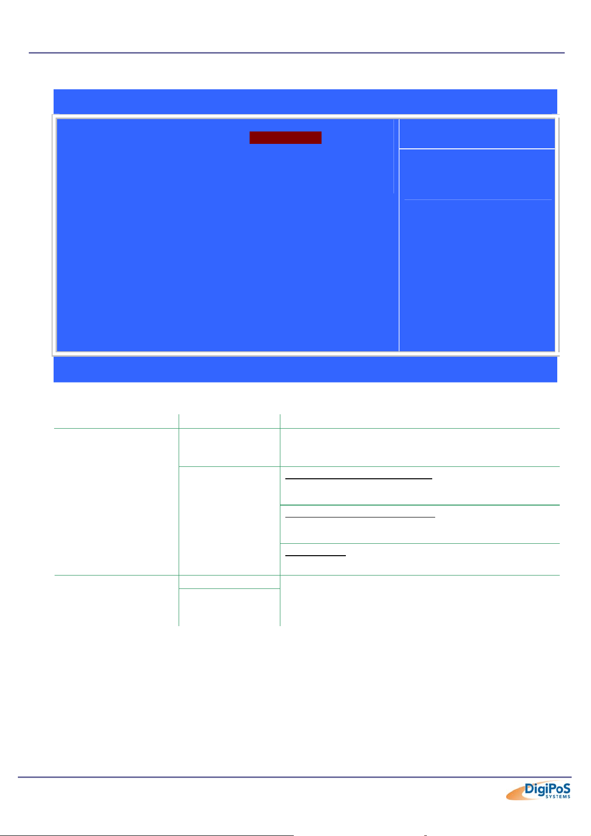
DigiPoS Millennium Technical Manual
Power Management Sub Menu
Phoenix – AwardBIOS CMOS Setup Utility
Power Management
Power Management [User Define]
HDD Power Down [Disable]
Doze Mode [Disable]
Suspend Mode [Disable]
Ç È Æ Å : Move +/-/PU/PD: Value F10 : Save ESC : Exit F1 : General Help
F5 : Previous Values F6: Fail-Safe Defaults F7 : Optimised Defaults
Menu Level ff
Item Help
Details
Feature Options Description
Power Management
User Define
Min Saving
Max Saving
This table
describes each
power
management
mode:
This option allows you to select the type (or degree) of
power saving for Doze, Standby and Suspend modes.
Minimum power management:
Doze Mode = 1 hr
Suspend Mode = 1 hr
Maximum power management:
Doze Mode = 1 min
Suspend Mode = 1 min
User Define:
Allows you to set each mode individually.
HDD Power Down
Disable
From 1 min
to 15 min Max
Page 60 of 81
By default, this item is disabled, meaning that no matter
the mode of the rest of the system, the hard drive will
remain ready. Otherwise, you have a range of choices
from 1 to 15 minutes.
Page 61

DigiPoS Millennium Technical Manual
Wake Up Events Sub Menu
Phoenix – AwardBIOS CMOS Setup Utility
Wake Up Events
VGA [OFF]
LPT & COM [LPT/COM]
HDD & FDD [ON]
PCI Master [OFF]
Modem Ring Resume [Disabled]
RTC Alarm Resume [Disabled]
Menu Level ff
Item Help
xDate (of Month) 0
xResume Time (hh:mm:ss) 0 : 0 : 0
Primary INTR [ON]
fIRQ’s Activity Monitoring [Press Enter]
Ç È Æ Å : Move +/-/PU/PD: Value F10 : Save ESC : Exit F1 : General Help
F5 : Previous Values F6: Fail-Safe Defaults F7 : Optimised Defaults
Details
Feature Options Description
VGA
LPT & COM
HDD & FDD
PCI Master
Modem Ring Resume
RTC Alarm Resume
Primary INTR
IRQ’s Activity Monitoring
OFF
ON
None
LPT
COM
LPT/COM
On
Off
On
Off
Disabled
Enabled
Enabled
Disabled
ON
OFF
-
Only valid if your monitor supports DPMS
This setting allows you to bring the DigiPoS out of Doze
or suspend mode if there is activity on either the LPT
port, Com Ports or Both.
This setting allows you to bring the DigiPoS out of Doze
or suspend mode if there is activity on either the HDD,
FDD or Both.
This setting allows you to bring the DigiPoS out of Doze
or suspend mode if there is activity on the PCI Bus
from any devices such as the network.
Reserved Function
Do Not Alter
This setting allows you to bring the DigiPoS out of Doze
or suspend mode at a specific time.
Selects the Primary Interrupt to either on or off.
Allows you to manually set which IRQ’s when activated
can bring the DigiPoS out of Doze or Suspend Mode.
Page 61 of 81
Page 62

DigiPoS Millennium Technical Manual
PnP/PCI Configurations
Phoenix – AwardBIOS CMOS Setup Utility
PnP/PCI Configurations
PNP OS Installed [Yes]
Reset Configuration Data [Disabled]
Resources Controlled By [Auto(ESCD)]
x IRQ Resources Press Enter
x DMA Resources Press Enter
PCI/VGA Palette Snoop [Disabled]
Assign IRQ For VGA [Disabled]
Assign IRQ For USB [Enabled]
Ç È Æ Å : Move +/-/PU/PD: Value F10 : Save ESC : Exit F1 : General Help
F5 : Previous Values F6: Fail-Safe Defaults F7 : Optimised Defaults
Menu Level ff
Select Yes if you are
using a Plug and Play
capable operating
system. Select No if
you need the BIOS to
configure non-boot
devices
Item Help
Details
Feature Options Description
PNP OS Installed
Reset Configuration Data
Resources Controlled By
IRQ Resources
Yes
No
Disabled
Enabled
Auto(ESCD)
Manual
Legacy ISA
PCI/ISA PnP
Select Yes if the operating system environment is Plugand-Play compatible (e.g., Windows 9x).
Normally, this field is Disabled. Select Enabled to reset
Extended System Configuration Data (ESCD) when you
exit Set-up if you have installed a new add-on device and
the system reconfiguration has caused such a serious
conflict that the operating system cannot boot.
The Plug and Play Award BIOS can automatically
configure all the boot and Plug and Play-compatible
devices. If you select Auto, all the interrupt requests (IRQ)
and DMA assignment fields disappear, as the BIOS
automatically assigns them.
When resources are controlled manually, assign each
system interrupt as one of the following types, depending
on the type of device using the interrupt:
Legacy ISA
bus specification, requiring a specific interrupt (such as
IRQ4 for serial port 1).
PCI/ISA PnP
standard, whether designed for PCI or ISA bus
architecture.
Devices compliant with the original PC AT
Devices compliant with the Plug and Play
Page 62 of 81
Page 63

DigiPoS Millennium Technical Manual
Detail Cont.
Feature Options Description
When resources are controlled manually, assign each
system DMA channel as one of the following types,
depending on the type of device using the interrupt:
Devices compliant with the original PC AT
Devices compliant with the Plug and Play
DMA Resources
PCI/VGA Palette Snoop
Assign IRQ For VGA
Assign IRQ For USB
Legacy ISA
PCI/ISA PnP
Disabled
Enabled
Disabled
Enabled
Disabled
Enabled
Legacy ISA
bus specification, requiring a specific interrupt (such as
IRQ4 for serial port 1).
PCI/ISA PnP
standard, whether designed for PCI or ISA bus
architecture.
Reserved Function
Do Not Alter
Reserved Function
Do Not Alter
If the USB ports are not being used, this function allows
you to release the IRQ that was being used for the USB
root hub.
Page 63 of 81
Page 64
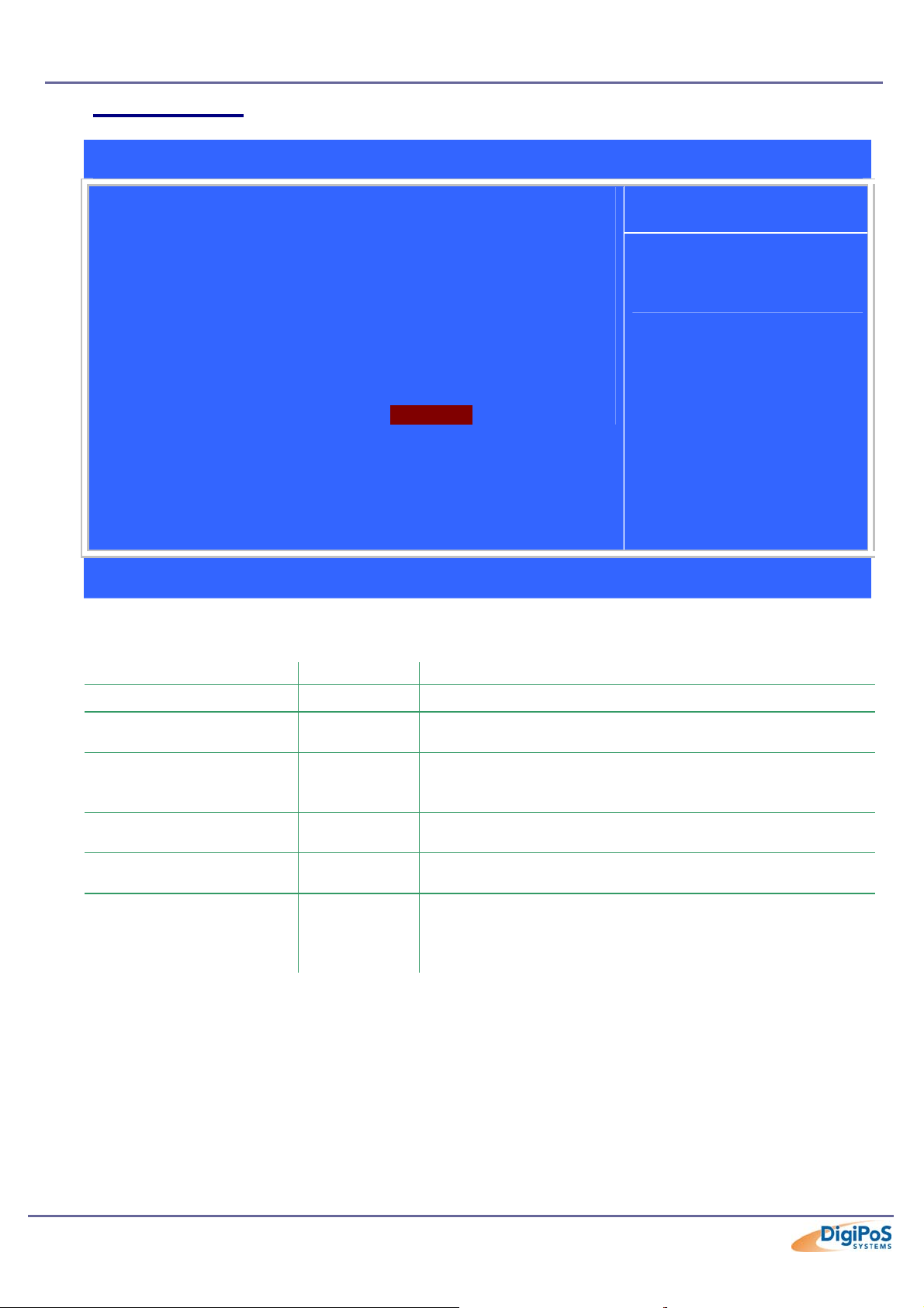
PC Health Status
DigiPoS Millennium Technical Manual
Phoenix – AwardBIOS CMOS Setup Utility
PC Health Status
Current CPU Temp. 36°C/96°F
Current System Temp. 39°C/102°F
Current CPUFAN1 Speed 6553 RPM
Current CPUFAN2 Speed 5041 RPM
VCore 1.77 V
2.5V 2.52 V
3.3V 3.31 V
5V 5.15 V
12V 11.88 V
2.5V 2.52 V
CPU Fan Warning Speed [Disabled]
Ç È Æ Å : Move +/-/PU/PD: Value F10 : Save ESC : Exit F1 : General Help
F5 : Previous Values F6: Fail-Safe Defaults F7 : Optimised Defaults
Menu Level f
Item Help
Details
Feature Options Description
Current CPU Temp - This gives the current temperature of the CPU case.
Current System Temp. -
Current CPUFAN1 Speed -
Current CPUFAN2 Speed -
Voltage Measurements -
Disabled
CPU Fan Warning Speed
4000 RPM
5000 RPM
6000 RPM
This gives the temperature of the temp junction inside the
CPU and NOT the DigiPoS system temperature.
This is the current speed of the CPU fan located opposite
the HDD (underneath the CD ROM if you have one fitted)
and is used for the air tunnel cooling system.
This is the current speed of the PSU fan located behind
the HDD.
These are real time voltage measurements from the
motherboard.
Select the lower limit for the CPU Fan speed. If the CPU
fan drops beyond the limit, a warning mechanism
programmed into your system will be activated.
Page 64 of 81
Page 65

DigiPoS Millennium Technical Manual
Frequency/Voltage Control
Phoenix – AwardBIOS CMOS Setup Utility
Frequency/Voltage Control
Auto Detect DIMM/PCI Clk [Enabled]
Spread Spectrum [Disabled]
CPU Host/PCI Clock [Disabled]
Ç È Æ Å : Move +/-/PU/PD: Value F10 : Save ESC : Exit F1 : General Help
F5 : Previous Values F6: Fail-Safe Defaults F7 : Optimised Defaults
Menu Level f
Item Help
Details
Feature Options Description
To reduce the occurrence of electromagnetic interference
Auto Detect DIMM/PCI Clk
Spread Spectrum
CPU Host/PCI Clock
Enabled
Disabled
Enabled
Disabled
Default
66/33Mhz
68/34Mhz
75/37Mhz
83/41Mhz
95/31Mhz
100/33Mhz
103/34Mhz
112/37Mhz
124/31Mhz
133/33Mhz
138/34Mhz
140/35Mhz
150/37Mhz
(EMI), the BIOS detects the presence or absence of
components in the ISA and PCI slots and turns off system
clock generator pulses to empty slots.
When the system clock generator pulses, the extreme
values of the pulses generates excess EMI. Enabling
pulse spectrum spread modulation changes the extreme
values from spikes to flat curves, thus reducing EMI. This
benefit may in some cases be outweighed by problems
with timing-critical devices, such as a clock-sensitive
SCSI device and is therefore not recommended.
Select Default or select a timing combination for the CPU
and the PCI bus. When set to Default, the BIOS uses the
actual CPU and PCI bus clock values which is the
recommended setting.
Page 65 of 81
Page 66

DigiPoS Millennium Technical Manual
Operating System Dependant Settings
The defaults that were covered above are generalised and some settings need to be
altered in order to gain the maximum performance from your DigiPoS when using certain
operating systems. The following list describes the operating system dependant settings
and their reasons.
DOS
Advanced Bios Features
Feature Options Reason
Video BIOS Shadow
Enabled
C8000-CBFFF Shadow
CC000-CFFFF Shadow
D0000-D3FFF Shadow
D4000-D7FFF Shadow
D8000-DBFFF Shadow
DC000-DFFFF Shadow
Enabled
Enabled
Enabled
Enabled
Enabled
Enabled
Advanced Chipset Features
OnChip USB
USB Keyboard Support
Enabled
Disabled
Enabled
Disabled
Integrated Peripherals
Sound Blaster
Disabled
Enabled
PnP/PCI Configurations
PNP OS Installed
Assign IRQ For USB
Disabled
Enabled
Yes
No
This enables you to move programs from 16 bit ROM
to 32 bit RAM since RAM is faster than ROM. This
can speed up video and other operations significantly
but only in DOS
Select Enabled only if you have USB peripherals such as a
Allows the multimedia device to run in a sound blaster
compatible mode. This may be necessary with some DOS
If the USB ports are not being used, this function allows
you to release the IRQ that was being used for the USB
keyboard or mouse.
Enables the use of a USB Keyboard
(Standard functions only)
software programs.
DOS is not Plug and Play Compatible.
root hub.
Page 66 of 81
Page 67

DigiPoS Millennium Technical Manual
Windows 95 & NT
The USB Support in Windows 95 (even OSR2) has never been ‘outstanding’ and we
therefore advise that this function is disabled if you are not using USB devices.
Advanced Chipset Features
OnChip USB
USB Keyboard Support
Enabled
Disabled
Enabled
Disabled
Select Enabled only if you have USB peripherals such as a
keyboard or mouse.
Enables the use of a USB Keyboard
(Standard functions only)
PnP/PCI Configurations
If the USB ports are not being used, this function allows
you to release the IRQ that was being used for the USB
root hub.
Assign IRQ For USB
Disabled
Enabled
Power Management
Please note that the Power Management settings should be left in their default state and
not activated under Windows NT as it is not supported and may cause system instability.
Windows 98, Me, 2000 & Xp
Please note that the Power Management settings should be left in their default state and
not activated
One reason is that Customers have stated that they do not want the system going into
standby as the system could be used at any moment and they do not want to wait while
the system recovers from either a doze or standby mode.
Windows Xp Special Notes
When installing Windows Xp from scratch, you must disable COM 3 & 4 in the Integrated
Peripherals section of the BIOS (First taking note of the settings) before installation has
commenced. Once the installation is complete, these ports can be re-activated. This is a
quirk between the VIA chipset and Windows XP’s plug and play hardware detection
routine.
Page 67 of 81
Page 68

DigiPoS Millennium Technical Manual
Fault Diagnosis
When a problem occurs with your DigiPoS, it is too easy to suspect complicated
electronics or to ‘suspect the worst’. This can lead an individual to become blinkered to
obvious solutions that will instantly rectify the fault.
Of the technical calls we receive from people having difficulties, simple issues that can
easily be resolved by the user attribute 90%. Before proceeding further into this guide,
please use the following checklist to eliminate a simple answer to your problem.
• Check the power cable is securely attached to the external power supply unit
and plugged into a ‘live’ socket supplying the correct voltage.
• The power switch on the power supply is on. When switched on the switch
should illuminate but the fan inside the power supply will not rotate until the
DigiPoS is switched on using the switch inside the front panel of the DigiPoS.
• The Plug from the power supply is firmly plugged into the DigiPoS and latched.
• None of the cables, power or otherwise are damaged or severed.
• Any peripheral devices (including Modem & Network Cables) are attached to
the DigiPoS are connected via the correct port and is orientated correctly.
• The VGA Cable is plugged in securely (using the screws) to the DigiPoS. The
DigiPoS will not boot and emit a beep error code if there is no VGA display
connected when the unit is powered up.
• There are no floppy disks or CD-ROM’s in the drives that would cause the
DigiPoS to boot from a device other than the master hard drive.
• Check the brightness and or contrast on the screen have not been turned down
or even that the screen has not been turned off. Although this sounds too
obvious, we still receive a number of calls where this is the cause of the
problem.
• The communication speed of the device is set the same as the DigiPoS. This
can cause the device not to work or display/ print ASCII characters randomly.
If any of the cables have come away from their respective connector on the rear of the
DigiPoS, DO NOT re-attach them (especially the Keyboard or any powered peripherals)
while the system is powered. The correct procedure is to power down the system, reattach the connector and then re-apply the power. If this is not done, significant damage
can result which is outside the terms and conditions of the warranty.
Page 68 of 81
Page 69
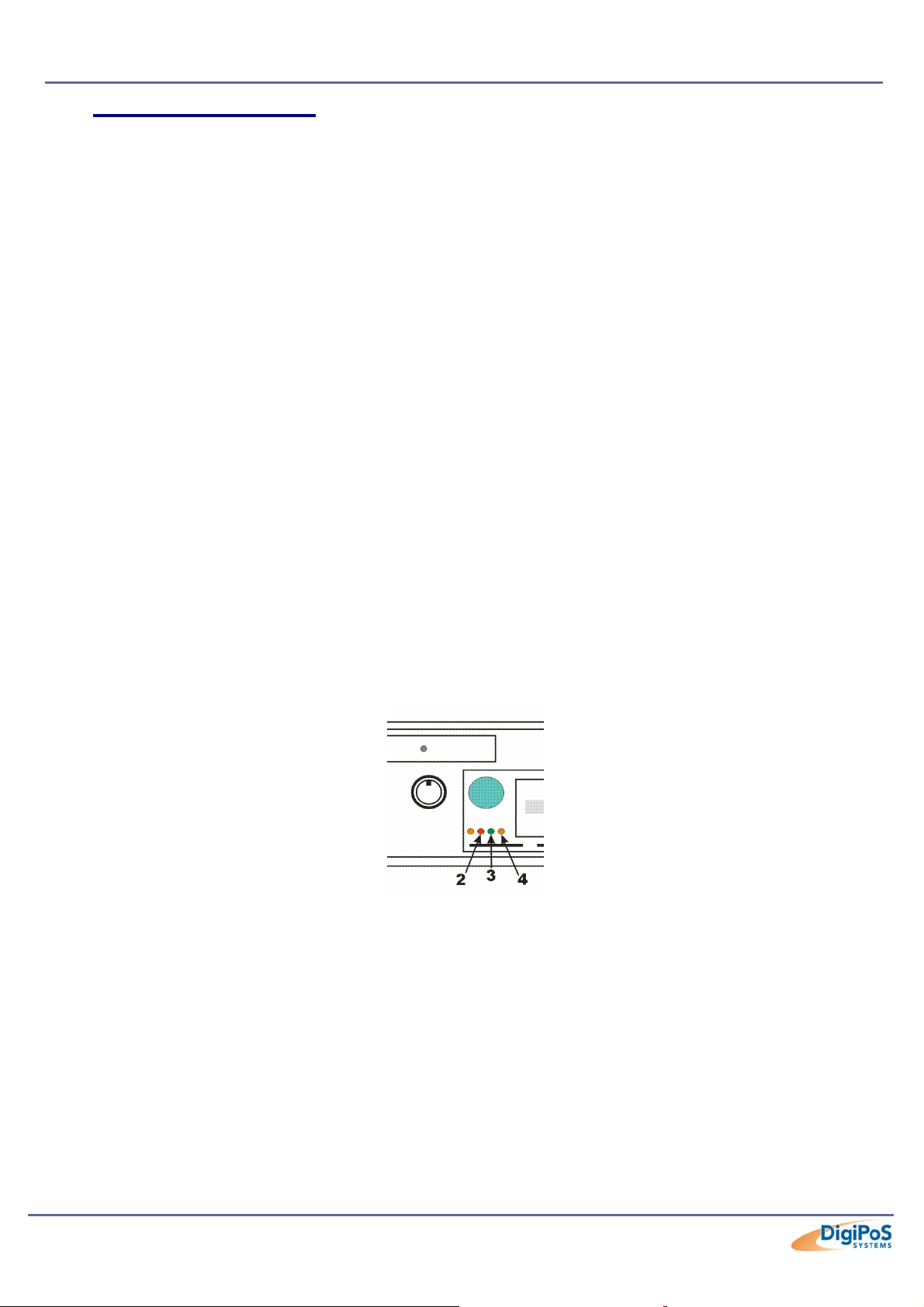
DigiPoS Millennium Technical Manual
Power Up Test Sequence
During the initial power up phase, the system board checks the internal operating
voltages. By observing certain conditions, it is possible to gain an initial indication of the
power status of the system. By following the observations below, initial fault diagnosis may
be undertaken.
• Check audible power up beep from system.
Caution is to be taken here as many people mistake the beep emitted by bar code
scanners to be the system beep. To be 100% certain, power down the system,
remove the bar code scanner and then re-test.
• Check the two cooling fans in system are working correctly.
This can be done without removing the case as the airflow can be felt by putting your hand
near the ventilation ports.
• Check external power supply fan is operative.
As stated before, the fan will only rotate when the DigiPoS is also switched on.
• Check HDD spins up to constant RPM.
• On the front panel, check the green LED is lit.
• On the front panel, check red LED is flashing as the HDD is accessed.
• On the internal front panel of DigiPoS Millennium check LED 2 3 & 4 are lit.
Please note that the fourth LED will be lit if you are in Diagnostic mode.
• On the external PSU of DigiPoS, the power switch is illuminated.
• The memory check completes, without error before the operating system call
is initiated.
At this point the system should exit the primary boot stage and allow the system to be
controlled by the user software such as Windows or Linux.
If this does not occur, record at which point the power up sequence fails and proceed to
the next section.
Page 69 of 81
Page 70

DigiPoS Millennium Technical Manual
Input / Output Port Testing
Before removing or re-inserting any of the connectors on the rear of the DigiPoS,
the system must be powered down (with the exception of the USB ports). Failure to
do this may result in severe damage not only to the equipment, but also to the
individual undertaking the work. Significant electrical voltages can be exposed
when a connector is removed and the system powered up.
Please use extreme caution
PS/2 Keyboard Port
If a fault is suspected with the keyboard port, first remove all devices connected to this
port including barcode scanners and programmable keyboards. Also remove any
adapters, gender changers or extension cables. Once this is done, attach a standard PS/2
keyboard that is a known good unit directly into the DigiPoS and boot the system into the
DigiPoS diagnostics program.
If the keyboard works correctly, the problem may be with one of the devices disconnected
in order to run this test effectively. Add each of the devices one at a time until the fault reoccurs which will indicate where the problem is.
If the keyboard port does not work correctly, the unit will have to be returned to DigiPoS
Systems for further fault analysis.
PS/2 Mouse Port
The only diagnosis available with this port is to try another mouse with a known good unit.
If this proves unsuccessful, the DigiPoS unit will have to be returned to DigiPoS Systems
for further investigation.
COM Ports
Should a loop back test be run on a DigiPoS Millennium, failure of this test does not
indicate a failure with the COM port. As the DigiPoS Millennium is able to supply power,
via the 9
standard loop back testing utilises Pin 9 in its standard form as the ring indicator in part of
the test.
The most appropriate way of testing a COM port is with a peripheral PoS device and
utilizing the DigiPoS diagnostics. As an example, when using an Epson TM-T88III, the
diagnostics will detect the presence of the COM port (as indicated in the top right hand
corner) and also the presence of the printer if it has been connected correctly. Once the
diagnostics has completed its initial search for devices, you can go into the printer sub
menu and test other functions. This proves the COM port and the associated cabling is
working correctly. It should also help to diagnose any orientation problems such as COM 1
& 2 being reversed, as the diagnostics will state where it has found the device.
VGA Port
Unless you have specialist equipment, the only way to test the output of the VGA port is to
connect a different monitor to the DigiPoS to see if it rectifies the problem. If it does not,
please go to the next chapter in this guide.
th
pin, to peripheral devices, normal loop back testing will fail. This is because
Page 70 of 81
Page 71

DigiPoS Millennium Technical Manual
LAN Port
Testing of a LAN connector and its output requires specialist equipment. If you suspect a
problem with the LAN socket of your DigiPoS, please try the following first before
contacting DigiPoS Systems:
• Check to see if the connector is firmly inserted into the socket and latched.
• Check to see that the connector is free from damage or dirt.
• Make certain that the cable is in good condition (Please note that any bends
smaller than 10 times the diameter of the cable can cause internal damage to the
cable not easily seen from the exterior)
• Check the Hub or Switch port where the cable is connected to see if there is any
indication of a ‘link‘ light or any other problem.
Parallel Port
An incorrect setting in the BIOS causes most parallel port problems. Before you connect
the device, please check the device manual and see if the device requires an SPP, EPP
or an ECP port.
If the port is set correctly, the next option is to try another device through the diagnostics
similar to the procedures described above for COM port testing.
Should the parallel port fail this test, please contact DigiPoS Systems to have a full
diagnostic workup on the DigiPoS to find the cause of the problem.
RJ12 Cash Drawer Loop Through
If there is a problem suspected with these connectors, connect the cash drawer directly
into the base of the printer and conduct a cash drawer fire test (either through the
Diagnostics or via other software). If this resolves the problem, please contact DigiPoS
Systems. If it does not, there is either a problem with the cash drawer or the PoS printer.
Sound Connectors
The only diagnosis available with these connectors is to try another output device such as
headphones that is known good. If this proves unsuccessful, please contact DigiPoS
Systems for further instructions.
USB Connectors
The only diagnosis available with this port is to try another device with a known good unit.
If this proves unsuccessful, the DigiPoS unit will have to be returned to DigiPoS Systems
for further investigation.
Page 71 of 81
Page 72
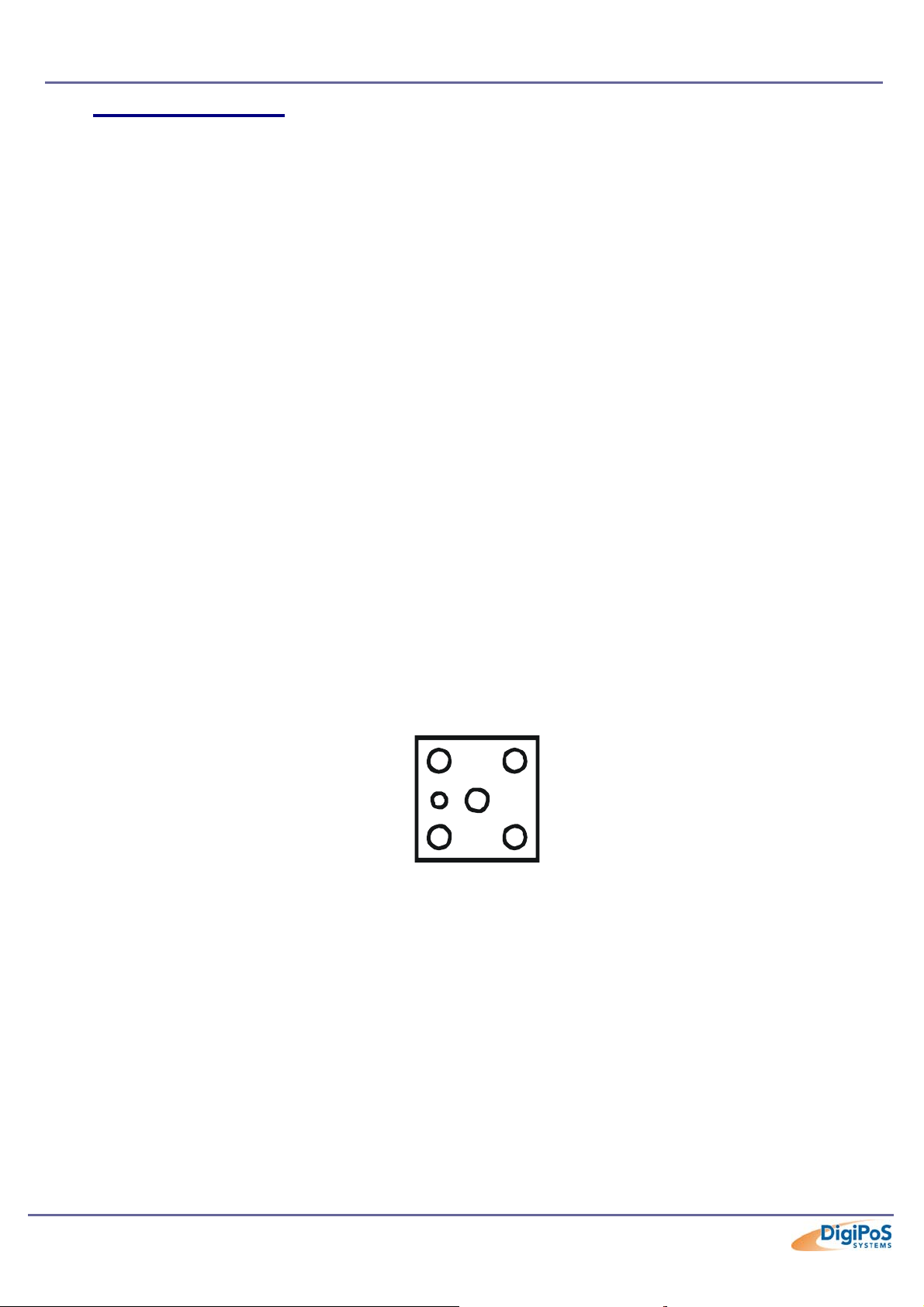
DigiPoS Millennium Technical Manual
Powered Port Testing
Before removing or re-inserting any of the connectors on the rear of the DigiPoS,
the system must be powered down (with the exception of the USB ports). Failure to
do this may result in severe damage not only to the equipment, but also to the
individual undertaking the work. Significant electrical voltages can be exposed
when a connector is removed and the system powered up.
Please use extreme caution
As each of the COM ports, the 2.5mm Barrel and the Hosiden connector are capable of
supplying power to peripherals, should a peripheral fail to power correctly or show an error
relating to power supply, the voltages supplied to these ports will have to be checked.
Before any in depth testing is carried out, please first check the condition of the relevant
fuse by removing it and testing it out of circuit as this is the first component designed to fail
in the event of a fault. DO NOT replace the fuse with another of higher rating other than
specified in this manual. Failure to do this will void the warranty and may also create a fire
hazard.
Voltage Level Checking
If you do not have access to a Multi-meter or you are uncertain how to measure DC
voltages, please contact DigiPoS Systems and DO NOT proceed with the following
section.
Firstly, measure the voltages available on the Power Distribution Board (PDB) and note
these down on the test sheet.
The voltages can be measured by removing a jumper (first noting its initial position) and
then probing the connections as follows:
24
12
Please check the test sheet for tolerance values.
5
9
Page 72 of 81
Page 73
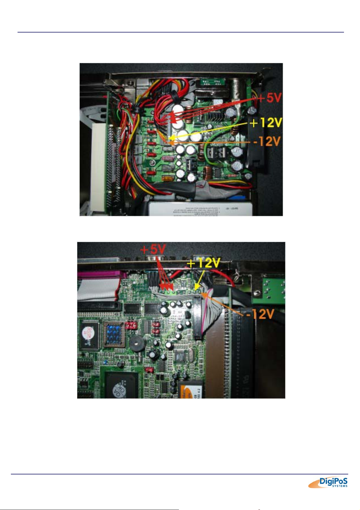
DigiPoS Millennium Technical Manual
Next, we need to check the voltages being distributed to the motherboard. These are
checked as follows:
And also on the motherboard side to confirm the cable is not damaged or incorrectly
connected:
If any of the voltages are missing or are outside of the tolerance values stated on the test
sheet, please contact DigiPoS Systems to arrange to have the DigiPoS serviced.
Page 73 of 81
Page 74

DigiPoS Millennium Technical Manual
Peripheral Component Check
Once all diagnostic tests and voltage tests have been completed, it is necessary to
establish that the peripheral components of the system are not faulty and causing
apparent motherboard failures or preventing the DigiPoS from completing a successful
boot. Replace each key component using the following the procedure.
• Power down the system.
• Using full Electrostatic discharge (ESD) precautions remove the memory, hard
drive, floppy drive, CD ROM and any expansion cards installed.
• Re-Install each component individually, re-booting the DigiPoS each time until all
components have been refitted or until the suspect device has been identified.
If none of the devices are found to be suspect, power down and replace the standard
peripheral devices and move to 1
st
level fault finding in the next chapter.
Page 74 of 81
Page 75

DigiPoS Millennium Technical Manual
1st Level Fault Finding
The objective of the 1st level test is to identify the possible area of failure and if a local
repair can be achieved or if the unit needs to be returned to DigiPoS Systems for further
testing and or repair.
System Does Not Boot
(Monitor is blank and there is no start-up sound from the system)
• Remove any installed PCI & ISA cards from the expansion slots and re-test.
• Make sure the RAM is installed correctly by removing it and re-installing it correctly.
• Check to see if there is any problem with the power (+5V, 12V & -12V).
No VGA Output
• Remove any installed PCI & ISA cards from the expansion slots.
• Reset the CMOS by installing a jumper on J7, switching on the DigiPoS briefly,
then switch off the DigiPoS and remove the jumper. Once this is done you will have
to into the BIOS and re-set all the parameters according to the technical manual for
correct operation of the DigiPoS.
•
Check the state of SW 2-1 to see if the onboard VGA adapter has been disabled.
Floppy disk failure
• Has the FDD drive been disabled in the BIOS?
• Does the Floppy disk cable show any signs of damage?
• Is the cable plugged in correctly taking note of the correct orientation for pin 1?
• Change the FDD drive with a known working unit and re-test.
• Are the connectors on the motherboard or the FDD in good condition with no bent
or misaligned pins?
• Is the POWER (+5V & +12V) within specified tolerances?
Hard disk failure
• Has the Hard drive been disabled in the BIOS?
• Does the Hard Drive disk cable show any signs of damage?
• Is the cable plugged in correctly taking note of the correct orientation for pin 1?
• Change the Hard Drive with a known working unit and re-test.
• Are the connectors on the motherboard or the HDD in good condition with no bent
or misaligned pins?
• Is the POWER (+5V & +12V) within specified tolerances?
• Has the Hard Drive jumpers been set correctly for either Master or Slave
configuration?
(Please check the individual drive type and contact DigiPoS Systems for the appropriate
setting)
Page 75 of 81
Page 76

DigiPoS Millennium Technical Manual
CD ROM Failure
• Has the CD ROM been disabled in the BIOS?
• Does the CD ROM cable show any signs of damage?
• Is the cable plugged in correctly taking note of the correct orientation for pin 1?
• Change the CD ROM with a known working unit and re-test.
• Are the connectors on the Riser Card or the CD ROM in good condition with no
bent or misaligned pins?
• Is the POWER (+5V & +12V) within specified tolerances?
COM port failure
• Remove any installed PCI & ISA cards from the expansion slots.
• Enter BIOS and make certain that the COM ports are active and set correctly.
• Check to see if the COM port cable (and DC power cables) inside the DigiPoS does
not show any signs of damage and are inserted into the correct sockets.
• Is there any problems with the –12V?
Parallel Port Failure
• Remove any installed PCI & ISA cards from the expansion slots.
• Enter BIOS and make certain that the LPT port is active and set correctly.
• Check to see if the LPT cable inside the DigiPoS is damaged and also is inserted
correctly into the motherboard.
Disk On Chip Failure
• Check that the jumper settings are correct.
• Check the orientation of the Disk on Chip is correct.
• Check to see if there is any external damage showing to the device and that all pins
are located in the socket correctly.
Onboard LAN Failure
• Check that the cable is inserted correctly and that it is the correct type of cable (Not
a cross over cable when connected to a hub etc.
• Check the BIOS to see if the onboard LAN is active and set correctly.
• Inspect the connectors inside the LAN socket on the rear of the DigiPoS for
damage or foreign objects.
• Use the RSET8139.EXE program to run further tests and diagnostics.
System Hold or Freeze
• Remove any installed PCI & ISA cards from the expansion slots.
• Enter the BIOS and check the settings are correct according to the type of
operating system used and the type of DigiPoS configuration.
• Make sure the RAM is installed correctly by removing it and re-installing it correctly.
• Run a full system diagnosis of all peripheral components including CPU, RAM,
HDD, FDD, Riser Card and CD ROM if fitted.
• A system freeze or hold can also be caused by a multitude of reasons within any
operating system or software. If you continue to experience problems with the
DigiPoS it is recommended that you re-install the operating system and or software.
Page 76 of 81
Page 77

DigiPoS Millennium Technical Manual
Test Sheet Completion
The following test result sheet should be used throughout the testing procedure to record
the failure condition of the DigiPoS. If after completing the procedure the DigiPoS cannot
be repaired locally, please contact your nearest DigiPoS Systems office and speak to a
technical representative to discuss the problems you are having. If you are asked to return
the DigiPoS, a copy of the test sheet must be forwarded to your local DigiPoS Systems
office observing any local RA procedures as this will help expedite the repair procedure.
After the repair process has been undertaken, the DigiPoS will be returned with a failure
notification attached. If no fault can be found then the technicians at the local DigiPoS
Systems office as well as the technical manager will undertake a training/diagnostic
investigation to prevent any equipment being returned with no fault found and to minimise
future disruptions to your operation.
Page 77 of 81
Page 78
DigiPoS Millennium Technical Manual
Test Sheet
System S/No: M/Board S/No:
Date of Test: Company Name:
Engineer: DigiPoS Systems Office:
Test Result
Comments Check List
Jumper Setting Check
850Mhz – Millennium
1Ghz - PowerPoS
Power Up Sequence:
OK
OK
Audible System Bleep OK Failed
Power ON LED OK Failed
HDD Constant RPM OK Failed
HDD Access LED Activates OK Failed
Video Enabled OK Failed
Failed
Failed
Memory Check OK Failed
Ext PSU Fan (When Power Applied) OK Failed
Ext PSU Switch Illumination OK Failed
BIOS Diagnostic Pass OK Failed
Voltage Check Comments Result OK Fail
+24V PDB
±5% = 22.8 – 25.2
+12V PDB
±5% = 11.4 – 12.6
+9V PDB
±5% = 8.55 – 9.45
+5V PDB
±5% = 4.75 – 5.25
+5V Main
±5% = 4.75 – 5.25
+12V Main
±5% = 11.4 – 12.6
-12V Main
±10% = 10.8 – 13.2
Peripheral
Actual V
Actual V
Actual V
Actual V
Actual V
Actual V
Actual V
Comments
Component Changes
CPU OK Failed
RAM OK Failed
HDD OK Failed
FDD OK Failed
CD ROM OK Failed
Page 78 of 81
Page 79

Notes
DigiPoS Millennium Technical Manual
Signed: Print:
Page 79 of 81
Page 80

DigiPoS Millennium Technical Manual
WARRANTY POLICY
Limited Warranty
This product is warranted to be free of defects in materials and workings. This warranty
period shall begin from the date of the accompanying invoice and will be in effect for a
period of 3 Years.
Warranty Return Procedures
The customer must call the DigiPoS Systems representative’s technical support
department or DigiPoS Systems directly first so that any primary fault diagnosis can be
carried out. If the fault remains, DigiPoS Systems will issue a Return Authorization form,
which must be filled out and returned with the following information:
1) Contact Name and Physical Address.
2) Phone Number including any area or country codes.
3) Model Number.
4) Serial Number.
5) Invoice Number.
6) Date of Purchase.
7) Detailed description of the fault.
Failure to provide complete and correct information will result in significant delays in
processing your application for a returns authorization. Once your request has been
processed, a Returns Authorization number will be issued and this must be attached to
the goods being returned. Only at this stage can the goods now be returned. Any
merchandise sent for repair without a valid Returns Authorization number correctly
displayed on the packaging will not be accepted and might incur additional costs. All
freight costs to return the DigiPoS back to DigiPoS Systems are the responsibility of the
customer except where special authorization for freight exemption has been granted by a
DigiPoS Systems management representative.
THE FOLLOWING SHALL VOID WARRANTY
Any unauthorized service, modification, tampering, any damages due to accident, misuse,
abuse and or operation outside of electrical specifications shall void the warranty. This
also includes modification of the specification of the DigiPoS as it was originally supplied
including hard drive, memory, CPU, floppy disk drives, expansion cards and any other
additional equipment not mentioned here specifically.
There will be charges for labour and/or materials for repairs carried out after the warranty
period has expired. Please call your nearest DigiPoS Systems office for a quotation on
post warranty service.
Page 80 of 81
Page 81

DigiPoS Millennium Technical Manual
DigiPoS Systems Global Office Locations
DigiPoS Systems Australia
Unit 7 / 10 Bradford Street,
Alexandria NSW 2015.
Tel: +61 (0)2 8338 3333
Fax: +61 (0)2 8338 3388
http://www.digipos-systems.com.au
DigiPoS Systems Deutschland GmbH
Flintsbacher Str. 6
80686 München
Tel: +49 (0) 89/51 777 333
Fax: +49 (0) 89/51 777 330
http://www.digipos-systems.de
DigiPoS Systems France
PARIVRY – Bât. Nº12
14, Rue Jules Vanzuppe
94200 Ivry Sur Seine
Tèl: (01) 49 59 90 00
Fax: (01) 46 58 24 51
http://www.digipos-systems.fr
DigiPoS Systems United Kingdom
Unit 4
Houndmills Industrial Estate
Hamilton Close
Basingstoke Hampshire RG21 6YT
Tel: +44 (0)1256 390700
Fax: +44 (0)1256 356112
http://www.digipos-systems.co.uk
DigiPoS Systems Nordic / Norway
Vestvollveien
N-2021 Skedsmokorset Norway
Tel: +47 64 836 700
Fax: +47 64 836 701
http://www.digipos-systems.com
DigiPoS Systems Switzerland
Zweigniederlassung
Kloten / Zurich
Lindenstr. 20
CH-8302 Kloten / Zurich Switzerland
Tel: +41 (0) 1 815 58 64
Fax: +41 (0) 1 815 58 59
http://www.digipos-systems.ch
DigiPoS Systems China
8F, Building A
1050, Huagiang North Shenzhen China
Tel: + 86(755) 8328-0265
Fax: + 86(755) 8328-0259
http://www.digipos-systems.cn
DigiPoS Systems North America
309B Commissioners Rd. W.
London, Ontario Canada 6J 1Y4
Tel: (519) 474 7987
Toll Free: 1 866 84 PC-POS
Fax: (519) 474 2598
http://www.digipos-systems.biz
DigiPoS Systems Nordic / Denmark
Hørkær 26
2730 Herlev Danmark
Tlf.: 7027 8300
Fax: 7027 8301
http://www.digipos-systems.com
DigiPoS Systems South Africa
Unit 6, Kyalami Cresent,
Kyalami Business Park,
Kyalami, Midrand, Gauteng, South Africa
Tel: +27 (0) 11 466 4000
Fax: +27 (0) 11 466 4038
http://www.digipos-systems.co.za
DigiPoS Systems Taiwan
12F, 120-11 Chung Shan Road,
Section 3
Chung Ho City
Taipei Taiwan ROC
Tel: + 886 2 2226 4055
Fax: + 886 2 2226 4052
http://www.digipos-systems.com
DigiPoS Systems Nordic AB / Sweden
PO Box 4005
Solna Strandvag 14
SE-171 04 Solna Sweden
Tel: +46 8 445 28 70
Fax: +46 8 98 15 20
http://www.digipos-systems.com
DigiPoS Systems Nordic / Finland
Kankurinkatu 4 – 6
FIN-05800 Hyvinkaa Finland
Tel: +358 19 8712 330
Fax: +358 19 8712 333
http://www.digipos-systems.com
Page 81 of 81
 Loading...