


DC-190
U L T R A C O U N T
Counting Scale
Version 4.0
Installation Manual

1.0Introduction
The DC-190 Ultra Count counting scale offers practical solutions for a full range of precision counting applications. Models with an internally mounted load cell are available in capacities of 1.0 to 100 pounds. Models with external platforms are available in capacities of 1.0 to 50,000 pounds. An ultra-high-resolution force balance can also be used as a sample scale.
Features include 200 item code storage, over/under weight and quantity checking capability based on programmable
setpoints, and an optional internal battery for standalone applications. The enhanced DC-190 Ultra Count software provides features not found in the standard DC-190 counting scale, including:
•Separate tare registers for each channel
•Selectable fields for RS-232 output
•32-character ID Code, part name, and lot number fields
•32-character operator identification can be held through ID Code changes (SPEC-selectable)
•Teraoka Code and numeric input without SPEC change
•Supports unit weight per piece and unit weight per 1000 (SPEC-selectable)
•Supports CR or CR/LF delimiter
•Supports output on stable (SPEC-selectable), output on stable and ≥ setpoint, output on stable and in target window (over/under) or not in target window (SPEC-selectable)
•Supports simultaneous connection to two printers
•Eltron 27xx series printers can use downloaded label format or fixed format installed in 190
•Code 128 support for Eltron and BCP-30 printers
•BCP-300 company name output can be edited or removed.
•Full barboard support
Trademark Note: Eltron® and Zebra® are registered trademarks of Zebra Technologies Corporation. Epson® is a registered trademark of Seiko Epson Corporation. PSC® and QuickScan® are registered trademarks of PSC Inc.
1.1Unpacking and Inspection
Immediately after unpacking, visually inspect the DC-190 Ultra Count to ensure all components are included and undamaged. If any items were damaged in shipment, notify Rice Lake Weighing Systems and the shipper immediately.
Ensure all accessories are removed from the cartons, then replace all packing materials in the cartons and store in a safe place. Use the original cartons whenever shipment of the scale is required.
1.2Repacking
If the DC-190 counting scale must be returned for modification, calibration, or repair, it must be properly packed with sufficient cushioning materials and the load cell must be locked to prevent damage to the load cell (see Section 2.1 on page 6).
Whenever possible, use the original carton when shipping the DC-190. Damage caused by improper packaging is not be covered by warranty.
1.3DC-190 Scale Capacities and Resolutions
Counting scales specify two types of resolution:
•Weight (or external) resolution
•Counting (or internal) resolution
Weight resolution is displayed in increments of the full scale capacity which is divided into weight increments. For example, a 5-lb scale divided into 10,000 display divisions would display weight with 0.0005 lb divisions (10,000 divisions x 0.0005 lb = 5.0 lb).
Counting resolution is based on the internal resolution of the scale. The weight and counting resolutions for the DC-190 singleand dual-platform capacities are listed below.
Tables 1-1 through 1-3 list the scale capacities and resolutions for all models of the DC-190 counting scales.
Model |
|
|
Capacity (lb) |
|
Weighing Resolution (lb) |
Internal Resolution (lb) |
Platform Dimensions |
||||||||
|
|
|
|
|
|
|
|
|
|
|
|
|
|
|
|
S-XL-1.0 |
|
|
1.0 |
|
|
|
0.0001 |
|
|
0.000001 |
|
|
6” x 8” |
||
|
|
|
|
|
|
|
|
|
|
|
|
|
|
|
|
S-XL-2.5 |
|
|
2.5 |
|
|
|
0.0002 |
|
|
0.0000025 |
|
|
7” x 10” |
||
|
|
|
|
|
|
|
|
|
|
|
|
|
|
|
|
S-XL-5.0 |
|
|
5.0 |
|
|
|
0.0005 |
|
|
0.000005 |
|
11” x 16” |
|||
|
|
|
|
|
|
|
|
|
|
|
|
|
|
|
|
S-XL-10 |
|
|
10.0 |
|
|
|
0.001 |
|
|
0.00001 |
|
|
|
|
|
|
|
|
|
|
|
|
|
|
|
|
|
|
|
|
|
S-XL-25 |
|
|
25.0 |
|
|
|
0.002 |
|
|
0.000025 |
|
|
|
|
|
|
|
|
|
|
|
|
|
|
|
|
|
|
|
|
|
S-XL-50 |
|
|
50.0 |
|
|
|
0.005 |
|
|
0.00005 |
|
|
|
|
|
|
|
|
|
|
|
|
|
|
|
|
|
|
|
|
|
S-XL-100 |
|
|
100.0 |
|
|
|
0.01 |
|
|
0.0001 |
|
|
|
|
|
|
|
|
|
|
|
|
|
|
|
|
|
|
|
||
|
|
|
Table 1-1. DC-190 S-XL Scale Capacities |
|
|
|
|||||||||
|
|
|
|
|
|
|
|
|
|
|
|
|
|
||
|
Capacity (lb) |
|
Weighing Resolution (lb) |
Internal Resolution (lb) |
|
Platform Dimensions |
|||||||||
|
|
|
|
|
|
|
|
|
|
|
|
|
|||
Model |
Scale 1 |
Scale 2 |
|
Scale 1 |
Scale 2 |
Scale 1 |
|
Scale 2 |
|
Sample |
|
Bulk |
|||
|
|
|
|
|
|
|
|
|
|
|
|
|
|
|
|
S-XD-1/10 |
1.0 |
10 |
|
0.0001 |
0.001 |
0.000001 |
|
0.00001 |
|
4” x 6” |
|
9” x 12” |
|||
|
|
|
|
|
|
|
|
|
|
|
|
|
|
|
|
S-XD-1/25 |
|
|
25 |
|
|
|
0.002 |
|
|
|
0.000025 |
|
|
|
|
|
|
|
|
|
|
|
|
|
|
|
|
|
|
|
|
S-XD-1/50 |
|
|
50 |
|
|
|
0.005 |
|
|
|
0.00005 |
|
|
|
|
|
|
|
|
|
|
|
|
|
|
|
|
|
|||
S-XD-2.5/25 |
2.5 |
25 |
|
0.0002 |
0.002 |
0.0000025 |
|
0.000025 |
|
|
|
|
|||
|
|
|
|
|
|
|
|
|
|
|
|
|
|
|
|
S-XD-2.5/50 |
|
|
50 |
|
|
|
0.005 |
|
|
|
0.00005 |
|
|
|
|
|
|
|
|
|
|
|
|
|
|
|
|
|
|
|
|
Table 1-2. DC-190 S-XD Scale Capacities

Model |
Capacity (lb) |
Weighing Resolution (lb) |
Internal Resolution (lb) |
Platform Dimensions |
|
|
|
|
|
S-SL-50 |
50 |
0.005 |
0.00005 |
13” x 17” |
|
|
|
|
|
S-SL-100 |
100 |
0.01 |
0.0001 |
|
|
|
|
|
|
S-SL-250 |
250 |
0.02 |
0.00025 |
|
|
|
|
|
|
S-TL-100 |
100 |
0.01 |
0.0001 |
17” x 21” |
|
|
|
|
|
S-TL-250 |
250 |
0.02 |
0.00025 |
|
|
|
|
|
|
S-TL-500 |
500 |
0.05 |
0.0005 |
|
|
|
|
|
|
S-UL-100 |
100 |
0.01 |
0.0001 |
24” x 28” |
|
|
|
|
|
S-UL-250 |
250 |
0.02 |
0.00025 |
|
|
|
|
|
|
S-UL-500 |
500 |
0.05 |
0.0005 |
|
|
|
|
|
|
NOTE: Other platform sizes are available. Consult factory for more information.
Table 1-3. Other S-Series Remote Platforms

1.4DC-190 Console
Figure 1-1 shows the DC-190 console with annunciators and numeric keypad. Annunciators are described in Section 1.4.1; Section 1.4.2 describes the DC-190 keypad.
Figure 1-1. DC-190 Keypad and Displays
1.4.1Annunciators
Table 1-4 shows a list of the annunciators that the DC-190 uses to provide additional information about the value being displayed. The annunciators are illuminated when the specific function is being performed.
Annunciator |
Annunciator Meaning |
|
|
ZERO |
Gross weight is at center of zero |
|
|
NET |
Display shows net weight (when tare weight is entered or recalled) |
|
|
GROSS |
Display shows gross weight |
|
|
INSUFF |
Net weight is below specified percentage of scale capacity |
|
|
RECOM |
Unit weight recomputing is possible |
|
|
BATT |
Battery power level is low |
|
|
MEMORY |
Quantity being accumulated or memory overflow error |
|
|
OUT |
Inventory out |
|
|
IN |
Inventory in |
|
|
UW/1000 Pcs |
UNIT-WEIGHT display value is equal to the weight of one piece, not 1000 pieces. Otherwise |
|
referred to as average piece weight (A.P.W.) |
|
|
MODE |
In programming mode |
|
|
lb |
Item weighed in lb units |
|
|
kg |
Item weighed in kg units |
|
|
SCALE NO. (1–4) |
Values shown in WEIGHT, UNIT-WEIGHT, and QUANTITY displays are for indicated scale. |
|
|
Table 1-4. DC-190 Panel Annunciators and Function
1.4.2DC-190 Keypad
Table 1-5 lists the keys and key functions of the DC-190 Ultra Count keypad (see Figure 1-1 on page 4).
|
|
|
|
|
|
|
Key |
|
|
Description |
|
|
|
|
|
|
|
|
|
|
|
|
|
|
|
|
|
|
through |
|
|
Used to enter numeric values. When using the scale, first enter a numeric value, then press the |
|
|
|
|
|
|
|
|
|
||
|
0 |
|
|
|
|
9 |
|
appropriate function key. |
||
|
|
|
|
|
|
|
||||
|
|
|
|
|
|
|
|
|
|
Used to enter numeric values containing a decimal point. NOTE: A numeric value must be entered |
|
|
|
|
|
|
|
|
|
|
|
|
|
|
|
|
|
|
|
|
|
before the decimal point. For example, .250 would be entered as 0.250. In normal mode, pressing |
|
|
|
|
|
|
|
|
|
|
the decimal key without entering a numeric value allows you to recall an item code from memory |
|
|
|
|
|
|
|
|
|
|
|
|
|
|
|
|
|
|
|
|
|
using the Teraoka Code (see Section 10.8 on page 58). |
|
|
|
|
|
|
|
|
|
|
|
|
|
|
|
|
|
|
|
|
|
Clears keyed-in data from the display starting with the last digit entered or clears keyed-in data all |
|
|
|
|
|
|
|
|
|
|
|
|
CLEAR |
|
|
|
|
at once (depends on SPEC 6, bit 2 setting). In normal weighing mode, can be used to clear the |
||||
|
|
|
|
|
|
|
|
|
|
unit weight with a unit weight already entered. When using a recalled item code, press CLEAR to |
|
|
|
|
|
|
|
|
|
|
|
|
|
|
|
|
|
|
|
|
|
clear both the unit weight and the tare weight. |
|
|
|
|
|
|
|
|
|
|
|
|
|
|
|
|
|
|
|
|
Switches display between pound (lb) and kilogram (kg). The scale powers up in the pound mode. |
|
|
|
|
|
|
|
|
|
|
||
|
kg |
|
|
|
|
|
|
|
||
|
|
lb |
|
|
|
|
|
|
|
|
|
|
|
|
|
|
|
|
|
|
|
|
|
|
|
|
|
|
|
|
|
|
|
|
|
|
|
|
|
|
|
|
Used to cycle through Scales 1 through 4. |
|
SCALE |
|
|
|
|
|
||||
|
|
|
|
|
|
|||||
|
|
|
|
|
|
|
|
|
|
|
|
|
|
|
|
|
|
|
|
|
|
|
|
|
|
|
|
|
|
|
|
Used to compute unit weight by sampling. Press the PIECES key after placing a 10-piece sample |
|
|
|
|
|
|
|
|
|
|
|
|
|
|
|
|
|
|
|
|
on the platform, or after using the numeric keypad to enter the sample size. On multichannel units, |
|
|
PIECES |
|
|
|
|
|
||||
|
|
|
|
|
|
|
|
|
|
the scale used must be selected. |
|
|
|
|
|
|
|
|
|
|
|
|
|
|
|
|
|
|
|
|
|
|
|
|
|
|
|
|
|
|
|
|
Used to set and clear tare weights in the normal weighing mode. |
|
|
|
|
|
|
|
|
|
|
|
|
|
TARE |
|
|
|
|
|
|
|
|
|
|
|
|
|
|
|
|
|
|
|
|
|
|
|
|
|
|
|
|
|
|
|
|
|
|
|
|
|
|
|
|
Used to reset the scale to zero. Also used in conjunction with other keys to enter the maintenance |
|
|
|
|
|
|
|
|
|
|
|
|
|
|
|
|
|
|
|
|
mode. The REZERO key will not function when the scale is in motion. |
|
|
REZERO |
|
|
|
|
|
||||
|
|
|
|
|
|
|
|
|
|
|
|
|
|
|
|
|
|
|
|
|
|
|
|
|
|
|
|
|
|
|
|
Used to enter a known unit weight using the numeric keypad. |
|
|
UNIT |
|
|
|
|
|
|||
|
|
|
|
|
|
|
||||
|
WEIGHT |
|
|
|
|
|
||||
|
|
|
|
|
|
|
|
|
|
|
|
|
|
|
|
|
|
|
|
|
|
|
|
|
|
|
|
|
|
Switches between net weight and gross weight display modes. Also used as an inventory key |
||
|
|
NET/ |
|
|
|
|
||||
|
GROSS |
|
|
|
|
(depends on SPEC 2, bit 0 setting). |
||||
|
INVENT |
|
|
|
|
|
||||
|
|
|
|
|
|
|
|
|
|
|
|
|
|
|
|
|
|
|
|
|
|
|
|
|
|
|
|
|
|
|
|
Used to enter the program mode. The MODE annunciator is illuminated when the scale is in |
|
|
|
|
|
|
|
|
|
|
|
|
MODE |
|
|
|
|
program mode and the WEIGHT display reads ProG. The quantity display shows the letter C and |
||||
|
|
|
|
|
|
|
|
|
|
the number of item codes in memory. |
|
|
|
|
|
|
|
|
|
|
|
|
|
|
|
|
|
|
|
|
|
|
|
|
|
|
|
|
Powers the scale on or off. |
||||
|
|
|
|
|
|
|
||||
|
ON |
|
|
|
|
|
|
|
||
|
|
OFF |
|
|
|
|
|
|||
|
|
|
|
|
|
|
|
|
|
|
|
|
|
|
|
|
|
|
|
|
|
|
|
- |
|
|
|
|
|
|
|
Used to operate the reduction function and to move between specification numbers (high to low) |
|
|
|
|
|
|
|
|
|
in SPEC setting mode. Also used to program part number in programming item codes. In |
|
|
|
|
|
|
|
|
|
|
||
|
|
DATE |
|
|
|
programming mode, it can be used for viewing or setting date/time. |
||||
|
|
|
|
|
|
|
|
|
|
|
|
|
|
|
|
|
|
|
|
|
|
+ |
|
|
|
|
|
|
|
Used to operate the accumulation function and to move between specification numbers (low to |
||
|
|
|
|
|
|
|
high) in SPEC setting mode. Also used to program set points in programming item codes. |
|||
|
|
|
|
|
|
|
|
|
|
|
* |
|
|
|
|
|
|
|
Used to store specification data in SPEC setting and program modes. Also used as a print key to |
||
|
|
|
|
|
|
|
transmit weight information. |
|||
|
PROG |
|
|
|||||||
|
|
|
|
|||||||
|
|
|
|
|
|
|
|
|
|
|
|
|
|
|
|
|
|
|
|
|
Used to recall item code data and to switch between item code inventory IN and OUT modes. |
|
CODE |
|
|
|
Also used to program commodity name in programming item codes. |
|||||
|
IN / OUT |
|
|
|||||||
|
|
|
|
|||||||
|
|
|
|
|
|
|
|
|
|
|
Table 1-5. DC-190 Keypad Keys and Functional Descriptions
2.0Installation
This section describes the procedure for the installation and setup of the DC-190 counting scale.
2.1Locking and Unlocking
Do not turn scale upside down. Always Caution work with scale on its side! Damage to
the load cell can occur if the scale is turned upside down.
The DC-190 counting scale is delivered in a locked position to prevent damage to the load cells during shipment.
To prevent damage to the load cells, Caution scale must be locked prior to shipment.
The scale uses either one setscrew for the single-platform scale or two setscrews for the dual-platform scale. The setscrews are located on the bottom of the base and must be removed before the scale is put into service. Use the following procedure to unlock your DC-190 counting scale.
1.Turn scale on side. Loosen locknut 1/4 turn (see Figure 2-1).
SINGLE-PLATFORM LOAD
CELL SETSCREW
DUAL-PLATFORM LOAD
CELL SETSCREWS
Figure 2-1. Location of Load Cell Setscrews for Singleand Dual-Platform Scales
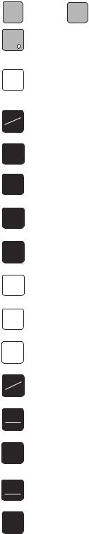
2.Remove load cell setscrew (see Figure 2-2) using the 2 mm hex wrench provided with scale.
NOTE: Keep locknut in the approximate original position on the setscrew to prevent damage to load cell when reinstalling.
NOTE: Beginning in 2003, setscrews with slotted heads will replace the hex head types, and will no longer require the 2mm hex wrench for removal.
LOAD CELL SETSCREW 

Figure 2-2. Setscrew Removal
3.Tape setscrews to the bottom of the scale or store in a safe location for possible future use.
2.2Setting Up
Place the scale on a solid, level surface away from fans, breezes, and sources of electrical interference.
Level the scale by turning the four adjustable legs located on the bottom of the scale while referencing the bubble level located on the back of the scale (see Figure 2-3).
NOTE: To ensure greater scale stability, turn in all four adjustable legs before leveling. Turn out adjustable legs to level as needed.
BUBBLE LEVEL
Figure 2-3. Bubble Level

2.3Powering Up the DC-190
The DC-190 can be operated either from an AC power source or with an optional rechargeable battery pack (DC power). The DC power allows the unit to be completely portable. Instructions for DC operation are contained in Section 2.3.3.
2.3.1AC Power Source
To power-up the DC-190 using the AC power cord:
1.Connect female end of AC power cord (Figure 2-4) under scale base.
LOAD CELL CABLE

 AC POWER CORD RECEPTACLE
Figure 2-4. Location of AC Power Cord Receptacle and
Load Cell Cable
2. Connect load cell cable from scale to Cable Port 1 in the back of the keyboard (Figure 2-5).
3.Plug the AC power cord into a grounded 115 VAC receptacle.
If the scale is connected to AC power while in the OFF condition, no warm-up is necessary.
NOTE: If the scale displays erratic data, it may be caused by a power transient. Turn the scale off and momentarily unplug it from the wall outlet. Then restart by plugging the scale back in and pressing ON/ OFF key. The scale will go through a display check; no warm up is needed.
2.3.2DC Battery Pack Replacement/Installation
An optional DC battery pack is available and may be purchased from RLWS to ship with the scale or retrofit in the field.
The battery pack is located in the bottom of the scale base and partial disassembly is required to install or replace it. Use the following procedure to install or replace the battery pack.
To prevent load cell damage, reinstall Caution setscrews before replacing battery.
1.Unplug scale from power source.
2.Remove scale platter.
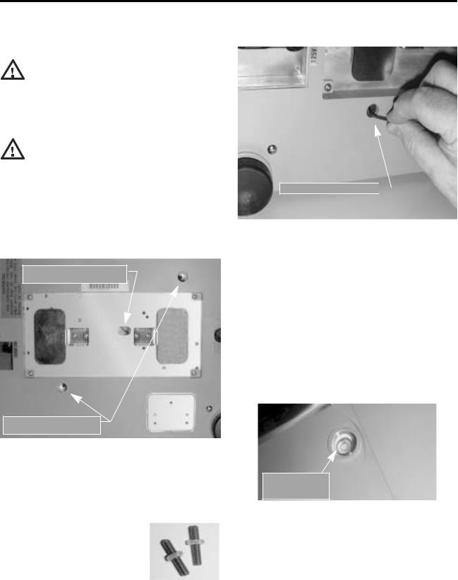
3.Remove the four platform support screws from the left-hand platform support assembly (shown in Figure 2-6). Remove the four screws from the right-hand platform support assembly.
4.Remove both platform support assemblies and set aside.
NOTE: The single-platform scale has four platform support (spider) screws while the dual-platform scale has four screws for each of the two platform supports.
CABLE PORT 2
CABLE PORT 1 

Figure 2-5. Scale Base Connector Ports
4.Press ON/OFF and allow scale to warm up for 10 minutes. The display momentarily shows the revision number, shows all digits from 0 to 9 in a count-up mode, goes blank, shows all 8s, and then enters normal weighing mode.
REMOVE PLATFORM SUPPORT SCREWS (DUAL-PLATFORM INSTALLATION)
Figure 2-6. Removing Platter Support Screws and Platter Support on a Dual-Platform Scale
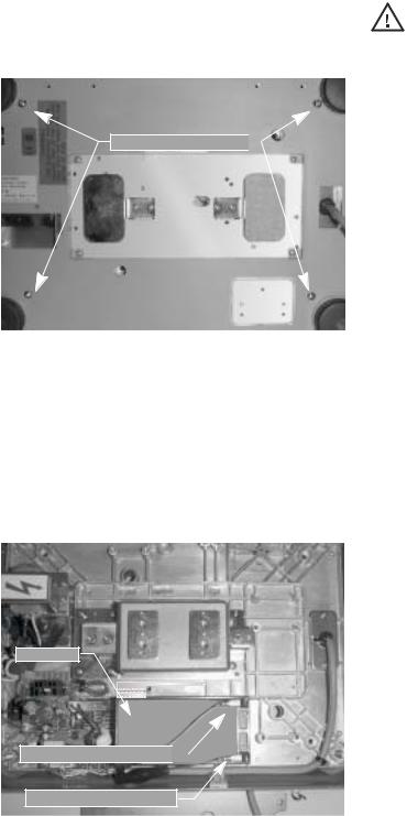
5.Place scale on side. Remove four top cover screws (shown in Figure 2-7). Set scale on legs and remove top cover.
TOP COVER SCREWS

Figure 2-7. Location of Top Cover Screws
6.Disconnect black (–) and red (+) electrical leads from battery (see Figure 2-8). Remove existing DC battery pack. Attach red lead to positive (+) side of battery.
7.Attach black lead to negative (–) side of battery.
8.Place new DC battery pack in battery compartment.
If the DC-190 scale is operated with the Caution battery pack removed, isolate the
positive (+) and negative (–) leads so that they do not make contact with each other or any part of the scale frame or any sensitive electronic components.
2.3.3DC Battery Operation
To power-up the DC-190 using the optional battery:
1.Remove AC power cord from bottom of scale.
2.Turn battery switch to ON (located on the bottom left-hand side of the scale base).
3.Press ON/OFF and allow scale to warm up for 10 minutes. The display momentarily shows revision number, shows all digits from 0 to 9 in a count-up mode, goes blank, shows all 8s, and then enters normal weighing mode.
2.3.4Battery Charging
A fully charged battery allows for approximately 4 hours of continuous use. Refer to SPEC 1 (Power Auto Off function) for extended hours of use. It will take approximately 8 hours to fully recharge a battery that has been completely dissipated. The console must be connected to the base during the recharge cycle and the AC power cord must be plugged in.
NOTE: Do not store the scale without turning off the battery power switch! When the battery switch is ON and the AC is not connected, a low level battery current will flow even if the display is OFF. To prevent battery discharge when stored, turn the battery switch OFF whenever the unit is not in use.
BATTERY
POSITIVE (+) TERMINAL 
NEGATIVE (-) TERMINAL
Figure 2-8. Battery Installation
9.Reassemble scale in the reverse order that it was disassembled.
10.Remove setscrew to unlock scale before placing the scale into service.
2.4Setting Time and Date
You can set the time and date printed on DC-190 print tickets. SPEC 5, bits 0 and 1 list three sequence variations of year, month, day that are available to enter dates into the DC-190 counting scale. Printed dates always appear in mmddyy format.
To set the date (month, date, and year) and time:
1.Press the MODE key.
2.Press the –/DATE key. The displays shows the date, day, and time.
3.Press the –/DATE key again. Enter month, day, year (mmddyy) on the keypad.
4.Press the –/DATE key. Enter the day (0=Mon, 1=Tue…6=Sun.
5.Press the –/DATE key. Enter the time of day using the 24-hour clock. For example, enter 1:35 p.m. as 1335.
6.Press the */PROG key to store the setting, or press the –/DATE key to exit without saving time and date.
2.5Installing Cable Strain Relief
To prevent load cell or peripheral cable damage from bending and twisting, cable strain reliefs are used in the back of the DC-190 keyboard. Each DC-190 counting scale comes equipped with these rubber strain reliefs and should be installed on initial scale setup.
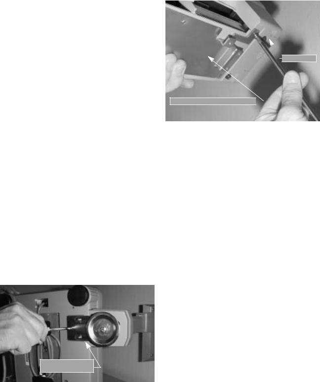
1.Remove the three 4 mm x 8 mm panhead screws securing the bracket to the back of the keyboard.
2.Remove rubber strain relief covering the two 14-pin load cell cable ports. If any peripheral devices are installed at this time, remove the rubber strain relief covering the peripheral cable access ports.
3.Route load cell and/or any peripheral device cables through opening in bracket. Connect cables to proper ports.
4.Install rubber strain relief over load cell/ peripheral cables and position into cavity. Gently pull cables to take up any slack.
5.When rubber strain reliefs are securely mounted, reinstall bracket using the three 4 mm x 8 mm panhead screws previously removed.
2.6Pole Mounting Instructions
1.Disconnect AC power cord from the bottom of the scale. Remove platform.
2.Remove the plastic cover from the upper mounting bracket.
NOTE: As a precaution, install load cell setscrew.
3.Turn scale on side.
4.Attach pole mount assembly to base using three 4 mm x 10 mm machine screws (shown in Figure 2-9).
POLE ASSEMBLY
MOUNT BRACKET
5.Route load cell and peripheral device cables through center of pole mount assembly.
6.Mount keyboard on bracket using six 4 mm x 10 mm machine screws (Figure 2-10).

 KEYBOARD
KEYBOARD MOUNT BRACKET
Figure 2-10. Attach Keyboard to Pole Mount Assembly
7.Attach load cell cable to Cable Port 1. If any other scales or peripheral devices are to be installed, remove plastic knockout from plastic shroud as required. Install plastic cover using two 4 mm x 8 mm panhead screws.
8.Install plastic cover over base of pole mount assembly.
9.Remove the load cell setscrew previously installed.
Figure 2-9. Attach Pole Mount Assembly to Base
 Loading...