

Page 1

Digi Connect® Sensor
User Guide
Page 2

Revision history—90001491
Revision Date Description
L October 2018
M April 2019
N May 2019
P December 2019 Removed HART® protocol information as it is no longer
R January 2021
Trademarks and copyright
Digi, Digi International, and the Digi logo are trademarks or registered trademarks in the United
States and other countries worldwide. All other trademarks mentioned in this document are the
property of their respective owners.
© 2021 Digi International Inc. All rights reserved.
Updated range specifications: Connect Sensor product
specifications.
Added LEDinformation.
Added information about the external power source and
battery usage.
Added gasket lubricant information.
supported.
Removed gasket lubricant information as it is no longer
needed.
Removed references to the abt/alm datapoint.
Removed information about the CEmark.
Disclaimers
Information in this document is subject to change without notice and does not represent a
commitment on the part of Digi International. Digi provides this document “as is,” without warranty of
any kind, expressed or implied, including, but not limited to, the implied warranties of fitness or
merchantability for a particular purpose. Digi may make improvements and/or changes in this manual
or in the product(s) and/or the program(s) described in this manual at any time.
Warranty
To view product warranty information, go to the following website:
www.digi.com/howtobuy/terms
Send comments
Documentation feedback: To provide feedback on this document, send your comments to
techcomm@digi.com.
Customer support
Digi Technical Support: Digi offers multiple technical support plans and service packages to help our
customers get the most out of their Digi product. For information on Technical Support plans and
pricing, contact us at +1 952.912.3444 or visit us at www.digi.com/support.
Digi Connect® Sensor User Guide
2
Page 3

Contents
Digi Connect® Sensor
Get started
Learn about Connect Sensor product components 8
Verify product components 8
Connect Sensor LEDs 10
Connect Sensor ports and buttons 12
Wake Connect Sensor 13
Set up a Connect Sensor 14
Safety information 14
Activate the SIMcard 15
Assemble Connect Sensor 16
Install the magnet mount 19
Configure the cellular connection 20
Check the cellular connection 22
Wire the I/O sensors 22
Add a device to Digi Remote Manager 22
Technical specifications
Maximum power and frequency bands 24
Connect Sensor product specifications 24
Cell modem transmit (TX) output power 25
Hardware
Battery inspection 26
Battery life 26
Battery percentage ranges and replacement 26
Battery passivization 27
Battery percentage and external power 27
CSENSE Continuous Monitoring power source 27
Connect Sensor hardware replacement 28
Firmware
CSENSE Continuous Monitoring firmware 29
Enable CSENSEContinuous Monitoring 30
Digi Connect® Sensor User Guide
3
Page 4

Enable continuous monitoring on digital input 30
Enable continuous monitoring on analog input 31
Configure the buffer time for continuous monitoring 31
Configure pins and protocols
Enable and configure analog inputs 33
Enable and configure analog power outputs 34
Enable and configure a digital input 35
Enable and configure a digital pulse counter 36
Enable and configure a digital output 37
Enable and configure a digital power output 38
Enable and configure the Modbus protocol 39
Enable and configure a serial power output 41
Modbus station addresses and locations 41
About analog and digital input options 43
Alarms 43
Hysteresis 44
Custom scaled sensor values 45
Oversampling 48
Schedule options 48
Immediate 48
One-Time 49
Recurring 49
Configure Connect Sensor device settings
Configure cellular options 50
Configure Remote Manager settings 51
Configure battery life percentage alarms 51
Battery life alarm and alarm notification 52
Create a battery life alarm for Connect Sensor devices 52
Configure the global battery alarm for a device 57
Configure internal temperature settings 58
Configure local interface settings: CLIand Bluetooth 59
Configure device (report) settings 60
View device information
View device information in Remote Manager 62
View battery life for a device in Remote Manager 63
View device and sensor data streams
Use Remote Manager to view device and sensor data streams 64
About data streams 64
View device data streams 65
Use the mobile app to view sensor data streams 66
Connect Sensor maintenance
Firmware updates 68
Digi Connect® Sensor User Guide
4
Page 5

Update the firmware using Remote Manager 68
Update firmware from Connect Sensor 69
Update the firmware using the CLI 69
Battery replacement 71
Remote Manager option definitions for Connect Sensor
Analog Current Loop Input and Voltage Input option definitions 73
Analog Power, Digital Power, and Serial Output option definitions 76
Cellular option definitions 77
Device Cloud option definitions 77
Device (report) settings option definitions 78
Digital Input option definitions 80
Digital Output option definitions 81
Toggle digital output on alarm 81
Digital Pulse Counter option definitions 83
Global Alarm Settings option definitions 84
Internal Temperature option definitions 85
Local Interface Settings option definitions 86
Modbus Protocol Settings option definitions 86
Data stream definitions
Group definitions for Connect Sensor data streams 89
Connect Sensor device-specific (ts1 and ui) data stream definitions 90
Analog input (ain and cl) data stream definitions 91
Analog (avout), digital (dvout1),and serial power output data stream definitions 92
Digital input (din1) data stream definitions 93
Digital output (dout1) data stream definitions 94
Digital pulse counter (pcnt1) data stream definitions 95
Temperature sensor (temp1) data stream definitions 95
Modbus (modb1) data stream definitions 96
Data streams for Modbus protocol 98
Use the CLI with Connect Sensor
Open a terminal program and use CLIcommands 99
Use the CLIto view status information for the device 101
Verify cellular network coverage using the CLI 101
View battery life using the CLI 102
CLI commands
fwupdate 104
status 104
set 105
Analog input CLI commands 106
Digital input CLI commands 109
Digital output CLI commands 111
Digital pulse counter CLI commands 112
Analog and digital power output CLI commands 114
Cellular CLI commands 115
Remote Manager CLI commands 117
Digi Connect® Sensor User Guide
5
Page 6

Internal temperature CLI commands 118
Modbus CLI commands 120
Troubleshooting
Connect Sensor LEDs for troubleshooting 121
Device not responding 121
Check the battery 121
Reset the device 121
Restore factory defaults to the device 122
Device not connected to the cellular network 122
Verify SIM configuration 122
Check cellular antenna 122
Verify cellular network coverage 122
Check battery life 123
Device does not connect to Remote Manager 123
Device does not appear in the mobile app 123
Verify Bluetooth connectivity 123
Reset the device 124
Regulatory information
FCC certifications and regulatory information 125
Declaration of Conformity (DoC) 125
Safety notices 126
Installation considerations 127
Warnings: Explosion hazards 128
RF exposure statement 129
UL/cUL conformity 129
Special conditions for safe use (ATEX) 129
ATEX marking 130
Digi Connect® Sensor User Guide
6
Page 7

Digi Connect® Sensor
Connect Sensor is a low-power cellular sensor gateway for wireless drop-in networking to remotely
monitor industrial environments and control systems, such as pipeline flow, air pressure, and light
levels. To power Connect Sensor, use either the internal battery or an external power source, such as
solar panels, for setups with no power or limited power.
Connect Sensor includes an external input/output (I/O) interface inside a waterproof enclosure for
connecting third-party sensors. The sensors gather information (sensor readings) from their
environment, and Connect Sensor reports that information to Digi Remote Manager® using a lowbandwidth cellular connection. You can sign in to your Remote Manager account to view the reports or
use the Digi Connect Wizard app on a mobile device and pair it with a nearby Connect Sensor to view
real-time sensor and device data in the field.
Note Make sure there is adequate cellular network coverage where you plan to install the gateway
before purchasing cellular service.
This guide shows you how to:
n Set up and maintain Connect Sensor
n Use Remote Manager to configure external sensors and data reports
n View sensor data and Connect Sensor system information
See the Digi Connect Sensor I/O Wiring Guide for details about wiring analog or digital I/O sensors and
power to Connect Sensor.
Digi Connect® Sensor User Guide
7
Page 8
Get started
Use the following sections to get started with Connect Sensor.
1. Learn about Connect Sensor product components
2. Set up a Connect Sensor
3. Add a device to Digi Remote Manager
4. Configure pins and protocols
5. Configure Connect Sensor device settings
Learn about Connect Sensor product components
These sections include a list of Connect Sensor components, and reference information about the
Connect Sensor LEDs, ports, and buttons.
Verify product components
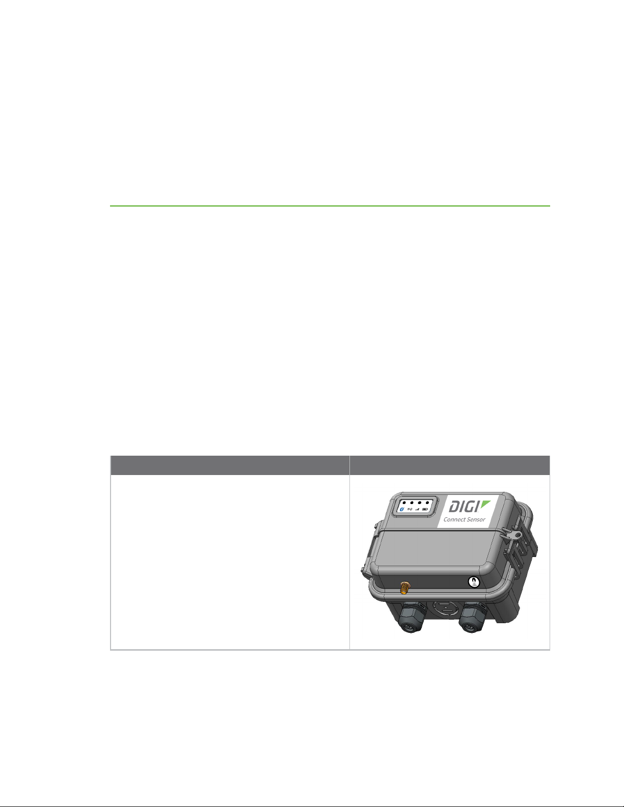
Connect Sensor includes the following components:
Component Description
Connect Sensor
Digi Connect® Sensor User Guide
8
Page 9
Get started Learn about Connect Sensor product components
Component Description
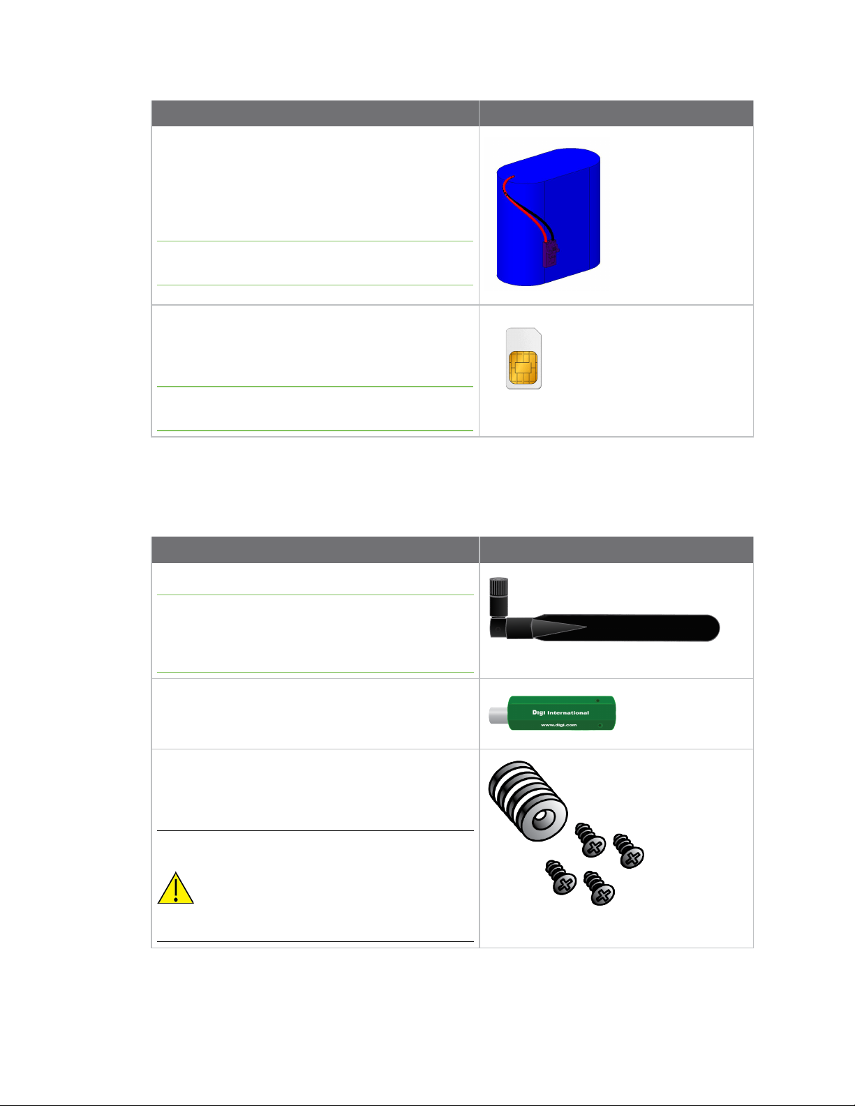
Battery
Connect Sensor uses a lithium metal battery. The
battery voltage is almost consistent from initial use
to near the end of the battery's useful life. See
Battery inspection for lithium battery safety
considerations.
Note The battery is included for all versions except
for the -N versions.
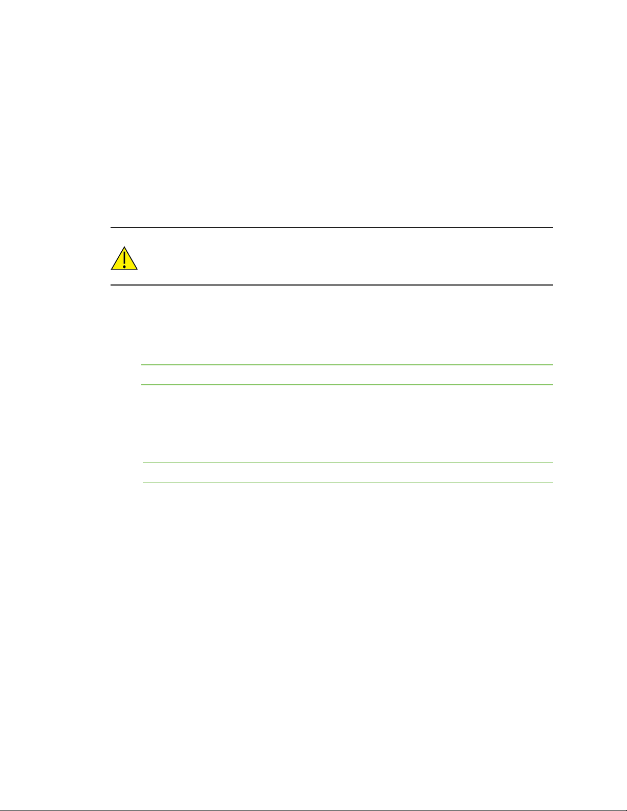
SIMcard
The SIMcard can be activated or replaced by an
activated SIMcard from your cellular service
provider.
Note If you have purchased Digi Bundled Services,
the SIMcard is activated by default.
Optional accessories
The following accessories are available through Digi International Inc. For more information, visit the
Digi Connect Sensor product page.
Component Description
Cellular antenna
Note This antenna is PN 76000926 and is an indoor-
only antenna. Only outdoor-rated antennas should be
used outdoors. For more information about antenna
options, see the Connect Sensor product page.
Magnet
Used for manually waking the device.
Magnet mount accessory pack
The pack includes four screws, and four magnets
separated by plastic discs. See Install the magnet
mount for installation instructions.
CAUTION! The magnets are extremely
powerful. Keep magnets separated. If
they touch each other they are difficult
to separate. Use caution when handling
the magnets to avoid injury due to
pinching.
Digi Connect® Sensor User Guide
9
Page 10
Get started Learn about Connect Sensor product components
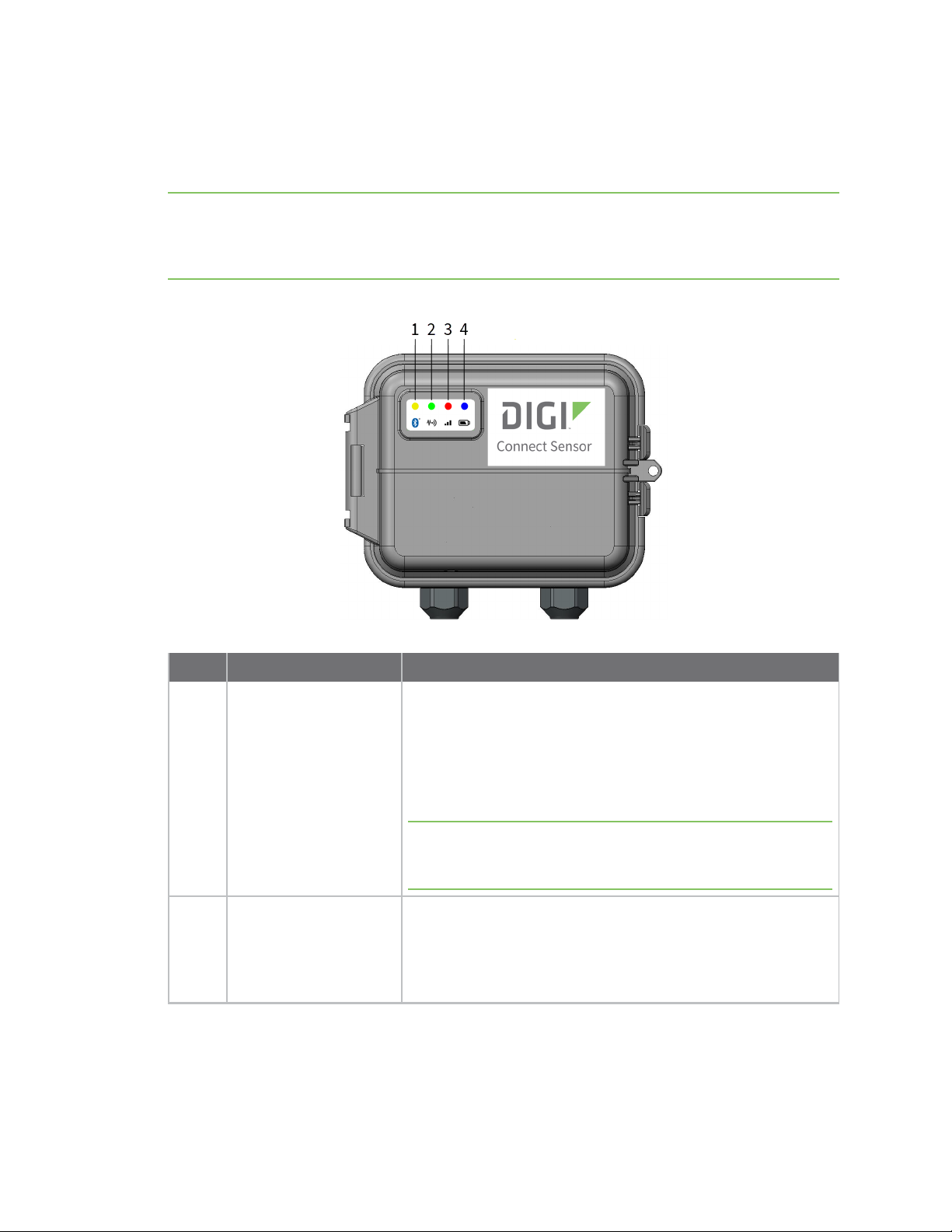
Connect Sensor LEDs
Connect Sensor has four LED indicators to monitor Bluetooth connection, sensor activity, cellular
connection, and battery life. If Connect Sensor is powered and all LEDs are off, it is in sleep mode.
Note The LEDindicators only light up when you wake the device by manual intervention: pressing the
Wake button on the device or using a magnet. When the device wakes up to take and push readings,
the LEDs do not light up since no one may be physically present to see the LED start-up sequence. See
Wake Connect Sensor for more information about the LEDindicators start-up sequence.
Item LED Description
1 Bluetooth
Indicator light for Bluetooth communication:
n Yellow blinking: Bluetooth is on and Connect Sensor is
discoverable. The LED blinks for up to 30 seconds.
n Yellow solid: A Bluetooth device is attached.
n Not lit: No Bluetooth devices were found or attached.
Note Bluetooth must be enabled on the Connect Sensor for the
Bluetooth LEDto light up. See Configure local interface settings:
CLIand Bluetooth.
2 Sensor reading
Indicator light for the sensor(s):
n Green blinking: One or more sensors are reading the
environment.
n Not lit: The LED turns off when readings are complete.
Digi Connect® Sensor User Guide
10
Page 11

Get started Learn about Connect Sensor product components
Item LED Description
3 Cellular
4 Battery
Indicator light for the cellular network connection:
n Solid purple: Connect Sensor is waking.
n Red blinking: Searching for the cellular network.
n Blue:
l Blinking: Connected to the cellular network and
attempting to communicate with Remote Manager
l Solid light: Successfully sent data to Remote
Manager. LED turns off after a few seconds.
Indicator light for battery function:
n Solid purple: Connect Sensor is waking
The following patterns are based on the Global Alarm >
Battery Life setting in Remote Manager:
n Red blinking: Indicates battery life is less than or equal to
the Battery Life alarm.
n Blue blinking: Indicates battery life is greater than the
Battery Life alarm.
Digi Connect® Sensor User Guide
11
Page 12
Get started Learn about Connect Sensor product components
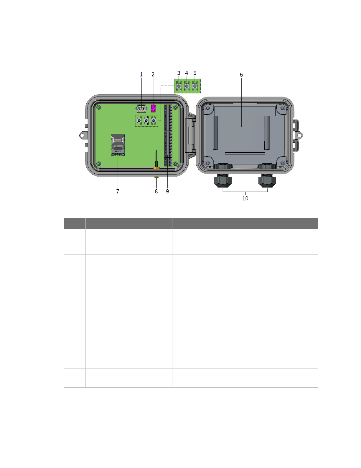
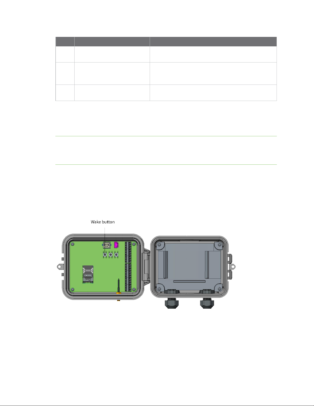
Connect Sensor ports and buttons
The following figure shows the controls for setting up and configuring Connect Sensor.
Item Name Description
1 Console port Connects
type A to B cable for access to the command line
interface (CLI).
2 Battery port
3 Wake button
.4 Factory button Removes all configuration changes and restores
5 Reset button Restarts the device when it is not responding to input
6 Battery tray Holds the battery in place.
7 SIM card tray Connects the SIMcard to
Connects the battery wire to power Connect Sensor.
Wakes Connect Sensor. See Wake Connect Sensor.
Connect Sensor
when you press and hold it for 3 seconds. If you press
this button, but do not hold it down, the device briefly
wakes and returns to sleep mode, and no settings are
affected.
(from the CLI or otherwise). Pressing this button does
not remove previous configuration changes.
inserted by default.
Connect Sensor
to its original factory default settings
to a computer using a USB
Connect Sensor
. A SIM card is
Digi Connect® Sensor User Guide
12
Page 13
Get started Learn about Connect Sensor product components
Item Name Description
8 Cellular antenna port Connects an external cellular antenna to
Sensor
.
9 Input/Output (I/O) interface
10 Cable glands Thread sensor cables through these openings into
Wire analog or digital input and output sensors or power
to this interface. For more information, see the Digi
Connect Sensor I/O Wiring Guide.
Connect Sensor
.
Connect
Wake Connect Sensor
If Connect Sensor is powered and all LEDs are off, it is in sleep mode. You can wake the device
manually, if needed.
Note The LEDindicators only light up when you wake the device by manual intervention: pressing the
Wake button inside the device or using a magnet. When the device automatically wakes up as
scheduled to take and push readings, the LEDs do not light up since no one may be physically present
to see the LED start-up sequence. See Connect Sensor LED start-up sequence.
Manually wake the device
To wake the device, you can either swipe a magnet across the top of the device, or press the Wake
button inside the device.
When you wake Connect Sensor, the LED buttons are activated as the device wakes up. The start-up
sequence is described below.
Connect Sensor LED start-up sequence
The LEDindicators light up in a predetermined sequence when you manually wake the Connect
Sensor. For a description of where the LEDs are located on the device, see Connect Sensor LEDs.
Digi Connect® Sensor User Guide
13
Page 14

Get started Set up a Connect Sensor
1. Press the Wake button inside the device or swipe a magnet across the device.
2. The cellular and battery LEDs light up purple for one second and then turn off.
3. The sensor LED blinks green as readings are taken and then turns off when readings are
complete.
4. If Bluetooth is enabled, the Bluetooth LED blinks yellow for 30 seconds. If a Bluetooth device is
attached, the Bluetooth LED turns solid and remains lit.
Note If Bluetooth is not enabled, the Bluetooth LED does not light up.
5. Connect Sensor takes and pushes data readings.
a. The Connect Sensor takes a battery life reading. The battery LED blinks either blue
or red, depending on the status of the battery life.
b. The cellular LED blinks blue until the connection to Remote Manager is complete.
c. The Connect Sensor pushes the data. When the data transfer is complete, the
cellular LED is solid blue.
d. After a few seconds, the cellular LED turns off.
CLIcommands and waking Connect Sensor
You can connect a USB cable from a computer to Connect Sensor and use CLIcommands to perform
actions on the device.
Connect Sensor has a 30-second timeout period between when a CLI command has been entered and
the command is processed. When Connect Sensor has finished processing the command, the device
goes to sleep, and "zzz... " appears in the terminal program.
If you press the Wake button or use a magnet to wake Connect Sensor during this 30-second timeout
period, the LED lights will not be activated, as the device is already awake. Make sure "zzz..." appears
in the terminal program before you try to wake the device.
See Open a terminal program and use CLIcommands for more details about this process.
Set up a Connect Sensor
Complete all of the tasks in this section in order to set up a Connect Sensor.
1. Review safety information
2. Activate the SIMcard
3. Assemble Connect Sensor
4. Configure the cellular connection
5. Check the cellular connection
6. Wire the I/O sensors
Safety information
The following safety information provides guidelines when assembling the Connect Sensor device. For
additional safety guidelines, see Safety notices.
Digi Connect® Sensor User Guide
14
Page 15

Get started Set up a Connect Sensor
CAUTION! The device is sensitive to electrostatic discharge (ESD).
The Connect Sensor device must be maintained only by Digi or a Digi qualified technician. Before
assembling the device, note the following:
n To avoid the risk of the battery falling into a protected area, do not assemble the device in the
installation area.
n Move the device to a non-hazardous and unclassified area before opening the enclosure and
connecting the hardware.
n Always use the designated battery, model number 76000912, from Digi International Inc.
n Allow only a trained technician to replace the lithium thionyl chloride batteries used in Connect
Sensor.
n Prior to installation, the battery should be inspected for any signs of damage. If the battery
appears to be damaged or is dropped during the installation, do not use the battery and
dispose of it properly. See Battery inspection for more information.
n You may be required to have a licensed electrician install or perform maintenance on this
equipment. Always follow applicable local, state, and federal codes and guidelines.
Activate the SIMcard
Follow this step if you need to activate your SIMcard. You can skip this step if:
n You purchased bundled services, and therefore have a pre-activated SIM card.
n You are using an activated SIMcard (standard size) from your cellular service provider.
Activate the SIM card provided by Digi
Connect Sensor has a SIM card inserted in the device by default. To use a cellular connection, you
must activate the inserted SIM card.
1. Note the Connect Sensor IMEI number. The IMEInumber is on the label on the device and on
the box the device was shipped in.
2. Activate the SIMcard.
a. Call Digi International Inc. at 952-912-3444 or 877-912-3444.
b. Press 3 for the Technical Support option.
c. Select the wireless data plan activation option. You will be asked to provide the
Connect Sensor IMEI number.
Activate a SIMcard not provided by Digi
You can activate a SIMcard from your cellular provider or from a supplier other than Digi.
Digi Connect® Sensor User Guide
15
Page 16
Get started Set up a Connect Sensor
1. Your SIM card provider will need the following information:
n Connect Sensor IMEI number: The IMEInumber is on the label on the Connect Sensor
device and on the box the device was shipped in.
n SIM card number: The SIMnumber is printed on the SIMcard.
2. Call your SIMcard provider to activate the SIMcard.
Assemble Connect Sensor
This section describes how to assemble Connect Sensor. Be sure to complete these steps before
wiring sensors to the I/O interface.
CAUTION! This product contains a lithium metal battery. Prior to installation, the
battery should be inspected for any signs of damage. If the battery appears to be
damaged or is dropped during the installation, do not use the battery and be sure to
dispose of it properly. See Battery inspection for more information.
Make sure you have the following equipment available:
n Activated SIMcard: See Activate the SIM card
n Battery
n Cellular antenna
Note You must use a passive (non-amplified) antenna with Connect Sensor.
Follow these steps to assemble Connect Sensor:
1. Open the Connect Sensor enclosure.
2. If desired, replace the existing SIM card with an activated SIMcard (standard size) from your
cellular service provider.
Note You can skip this step if you are using the existing SIM card inserted in the device.
a. Orient Connect Sensor to match the picture below.
Digi Connect® Sensor User Guide
16
Page 17
Get started Set up a Connect Sensor
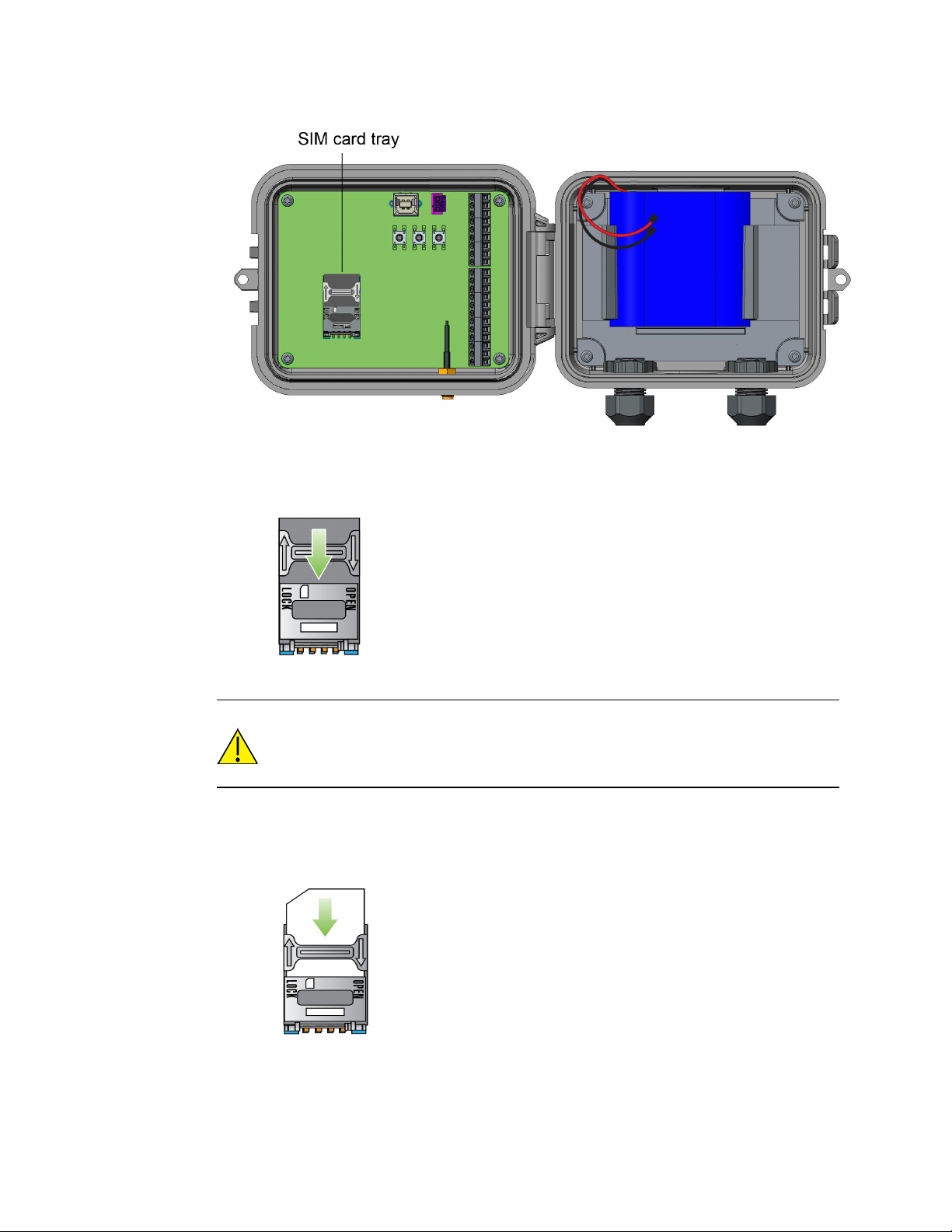
b. Unlock the SIM card tray by gently pushing the metal bar toward the bottom of the
tray.
c. Open the SIMcard tray by pulling the tray up from the top or right side of the tray.
CAUTION! Do not pull the SIMcard tray up from the left side or use a tool to
open the tray. These actions may damage the SIM detect switch, which is
beneath the left side of the tray.
d. Remove and discard the existing SIM card from the SIMcard tray.
e. Insert your own SIM card into the SIMcard tray, with the metal contacts face-down
and the flat edge inserted into the holder.
f. Press the SIMcard tray onto the board.
Digi Connect® Sensor User Guide
17
Page 18
Get started Set up a Connect Sensor
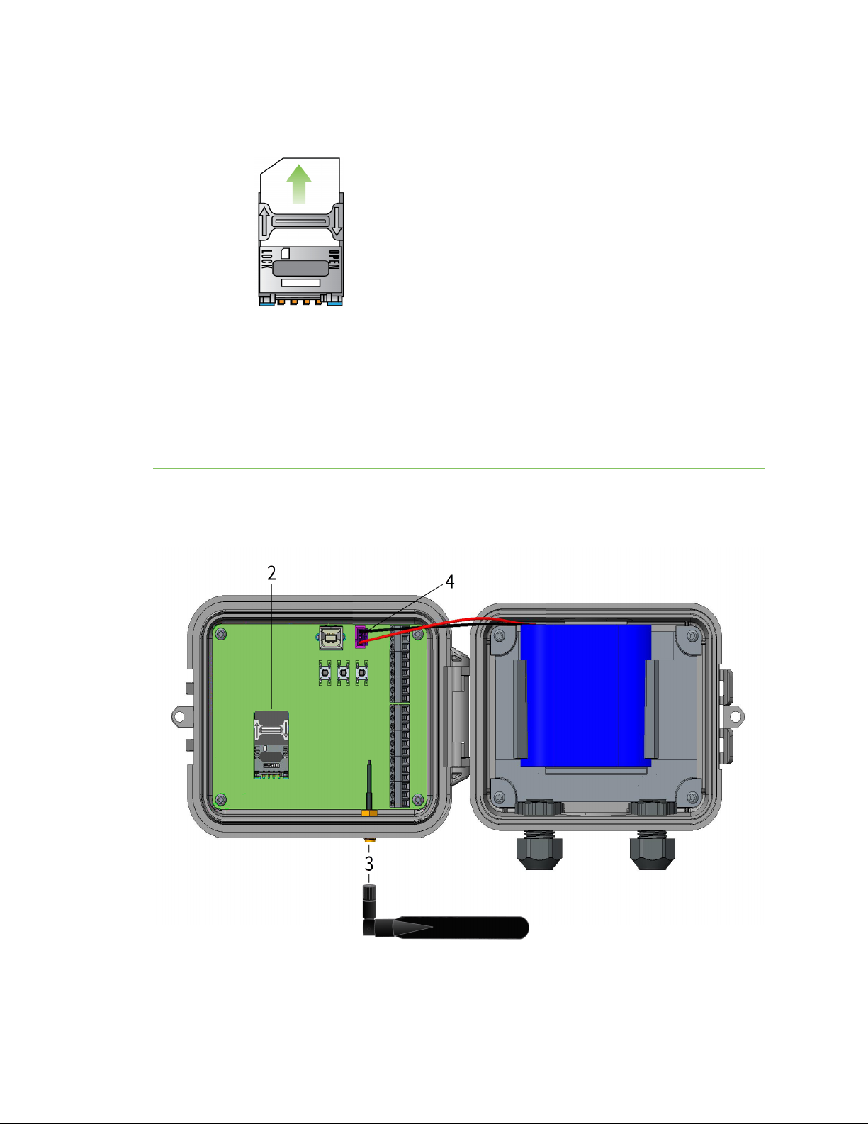
g. Lock the SIM card tray by gently pushing the metal bar toward the top of the
SIMcard holder.
3. Connect the cellular antenna.
4. Insert and connect the battery.
5. Close the cover on the device. The cover snaps into place.
6. Optional: Install the magnet mount to the bottom of Connect Sensor if you have purchased this
accessory. See Install the magnet mount.
Note It is recommended that you complete configuration, including verifying cellular and Remote
Manager connectivity, before wiring external sensors to Connect Sensor. See the Digi Remote Manager
User Guide for information about Remote Manager.
Digi Connect® Sensor User Guide
18
Page 19
Get started Set up a Connect Sensor
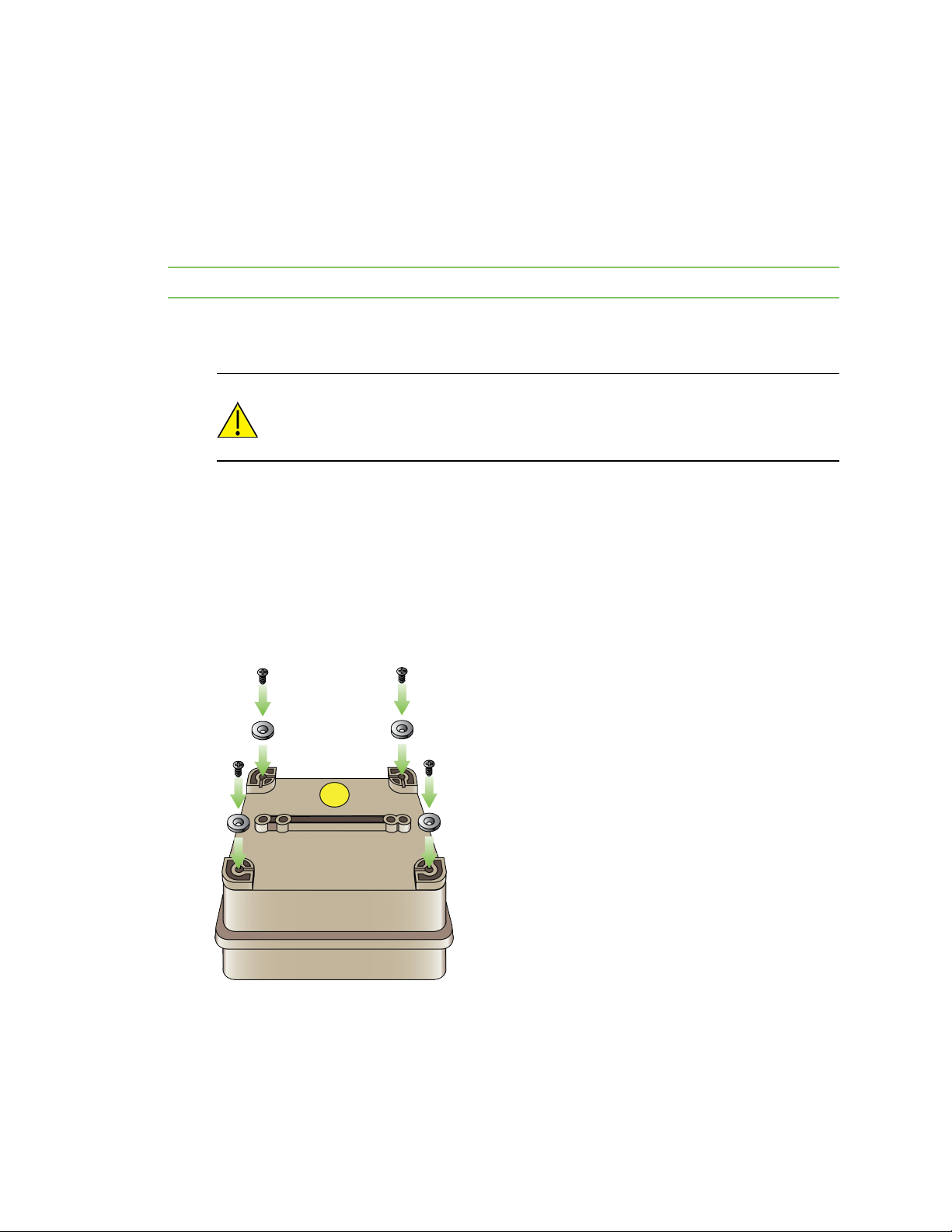
Install the magnet mount
You can install a magnet mount on Connect Sensor so that you can securely place the device on a
metal object.
Make sure you have the following equipment available:
n Magnet mount accessory pack. See Verify product components for purchasing information.
n Appropriate screw driver.
Note You can skip this step if you did not purchase the magnet mount accessory pack.
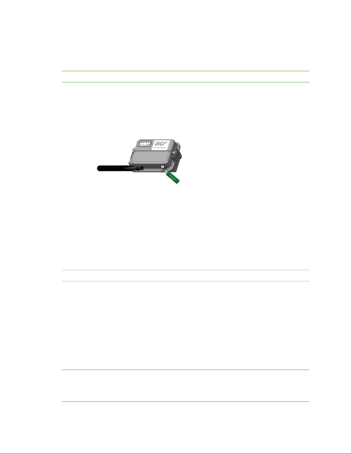
1. Turn Connect Sensor to access the bottom of the device.
2. Remove one magnet from the set of four magnets in the accessory pack.
CAUTION! The magnets are extremely powerful. Keep magnets separated. If
they touch each other they are difficult to separate. Use caution when handling
the magnets to avoid injury due to pinching.
3. Place the magnet on one corner of the device. Be sure to match the hole in the magnet to the
hole in the corner.
4. Remove one of the screws from the accessory pack.
5. Using the screwdriver, screw the magnet onto the device.
6. Repeat this process to screw the remaining magnets onto the corners of Connect Sensor.
When you have completed this process, a magnet should be screwed onto each corner of the
device.
Digi Connect® Sensor User Guide
19
Page 20
Get started Set up a Connect Sensor
Configure the cellular connection
Note If you purchased Digi Bundled Services, the cellular connection is already configured on your
Connect Sensor and you can skip this section.
Connect Sensor is configured with a default APN that you need to change to register Connect Sensor
on the cellular network for your cellular service provider. Use the command line interface (CLI) to
initially configure the cellular connection.
Before you begin, make sure you have the following required equipment and information:
n Computer running a terminal emulator program
n USB type A to B cable
n APN from your cellular service provider
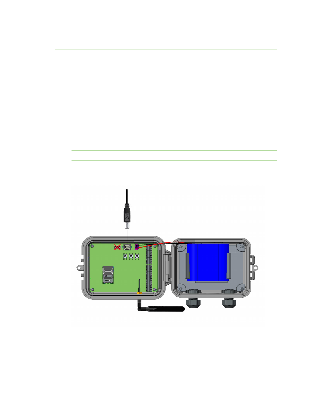
To register Connect Sensor on a cellular network:
1. Open the enclosure and make sure the battery is connected and the SIM card is installed.
2. Connect a USB type A to B cable from your computer to the USB type B port.
Note Do not use the mini USB port, which is covered by a red X in the graphic below.
You may need to install device drivers or wait for your computer to automatically install them
when connecting Connect Sensor to a computer using a USB cable. Digi recommends drivers
available at www.ftdichip.com/Drivers/VCP.htm.
Digi Connect® Sensor User Guide
20
Page 21

Get started Set up a Connect Sensor
3. Open a terminal program on a computer and connect to Connect Sensor using the following
configuration:
n Connection port: Connect to the COM port associated with the USB cable connected to
Connect Sensor
n Baud rate or bits per second: 115200
n Data: 8 bit
n Parity: None
n Stop: 1 bit
n Flow control: None
4. Press the Wake button on the device.
5. At the command prompt, type set apn=<yourCarrierAPN> where yourCarrierAPN is the string
supplied by your cellular service provider.
6. Press Enter. The terminal program displays the APN configuration setting’s current value and
the pending value.
7. If required, set a user name, password, and PIN for the SIMcard. At the command prompt, type
the following and press Enter after each command:
o
set usr=<username>
Where username is the name of your cellular account.
o
set pwd=<password>
Where password is the password for your cellular account.
o
set pin=<pin>
Where pin is the PIN for your SIMcard.
For details about these commands, see CLI commands.
8. Type activate at the command prompt and press Enter to immediately make the change.
Connect Sensor goes to sleep and immediately wakes up to report the change to Remote
Manager. After the change completes, it goes to sleep again.
9. (Optional) Verify the new settings:
a. Press the Wake button.
b. At the command prompt type set commandname where commandname is one of
the settings you updated, such as apn.
After setting up and configuring Connect Sensor, use the following sections in this guide to configure
additional settings and remotely manage Connect Sensor:
n Check the cellular connection
n Configure pins and protocols
n Configure Connect Sensor device settings
n View device and sensor data streams
Digi Connect® Sensor User Guide
21
Page 22
Get started Add a device to Digi Remote Manager
Check the cellular connection
Make sure the cellular network provides an adequate signal where you install Connect Sensor to
maintain a consistent cellular connection.
Note Proper network coverage helps reduce power consumption, leading to improved battery life.
To check the cellular network connection at the install location:
1. Wake Connect Sensor:
n If the enclosure is open, press the Wake button.
n If the enclosure is closed, swipe the magnet across the magnet icon on the outside of
the device.
2. The LEDindicators light up in a predetermined sequence when you manually wake the device.
3. If Connect Sensor does not connect to the cellular network, see Device not connected to the
cellular network.
You can now complete I/O interface wiring, see the Digi Connect Sensor I/O Wiring Guide.
Wire the I/O sensors
You can wire the analog and digital input/output sensors or power using the I/O interface. For detailed
information, see the Digi Connect Sensor I/O Wiring Guide.
Note All external or field wiring must be in accordance with NFPA 70 Article 501.10(B).
After wiring sensors, use the following sections in this guide to configure additional settings and
remotely manage Connect Sensor.
n Configure pins and protocols
n View device and sensor data streams
n Configure Connect Sensor device settings
Add a device to Digi Remote Manager
To remotely manage Connect Sensor and get sensor data, you need to create a Remote Manager
account and add your Connect Sensor device to your account.
Note To serve our customers most effectively, Digi International Inc. is consolidating its cloud
services, Digi Device Cloud and Digi Remote Manager®, under the Remote Manager name. This phased
process does not affect device functionality or the functionality of the web services and other
Digi Connect® Sensor User Guide
22
Page 23

Get started Add a device to Digi Remote Manager
features. However, you will find instances of both Device Cloud and Digi Remote Manager in some
documentation, firmware, and user interfaces.
Note If you purchased Digi Bundled Services, the following steps were completed for you. You can skip
this section.
To add a device to Remote Manager:
1. Sign in to your Remote Manager account:
n If you need to create an account, go to Remote Manager at remotemanager.digi.com,
click Sign up, and complete the form to create your account.
n If you already have an account, go to Remote Manager at remotemanager.digi.com and
sign in with your user name and password.
2. Locate the 15-digit device IMEI number on the Connect Sensor label.
3. Click Device Management > Devices.
4. Click Add Devices. The Add Devices dialog appears.
You cannot use the Discover button to discover Connect Sensor devices automatically because
the devices are not available on the local network.
5. From the Add Devices drop-down menu, select IMEI, and enter the number.
6. Click Add to add the device.
7. Click OK to close the Add Devices dialog. The device appears in the Device Management list.
Note If the device does not display in the Device Management list, you can wake Connect
Sensor to force a connection with Remote Manager and update the data. For instructions, see
Update the firmware using the CLI or Update firmware from Connect Sensor.
8. Click Refresh if the device data does not appear on its own after a short period of time.
Device data appears after the first time it communicates with Remote Manager.
Digi Connect® Sensor User Guide
23
Page 24
Technical specifications
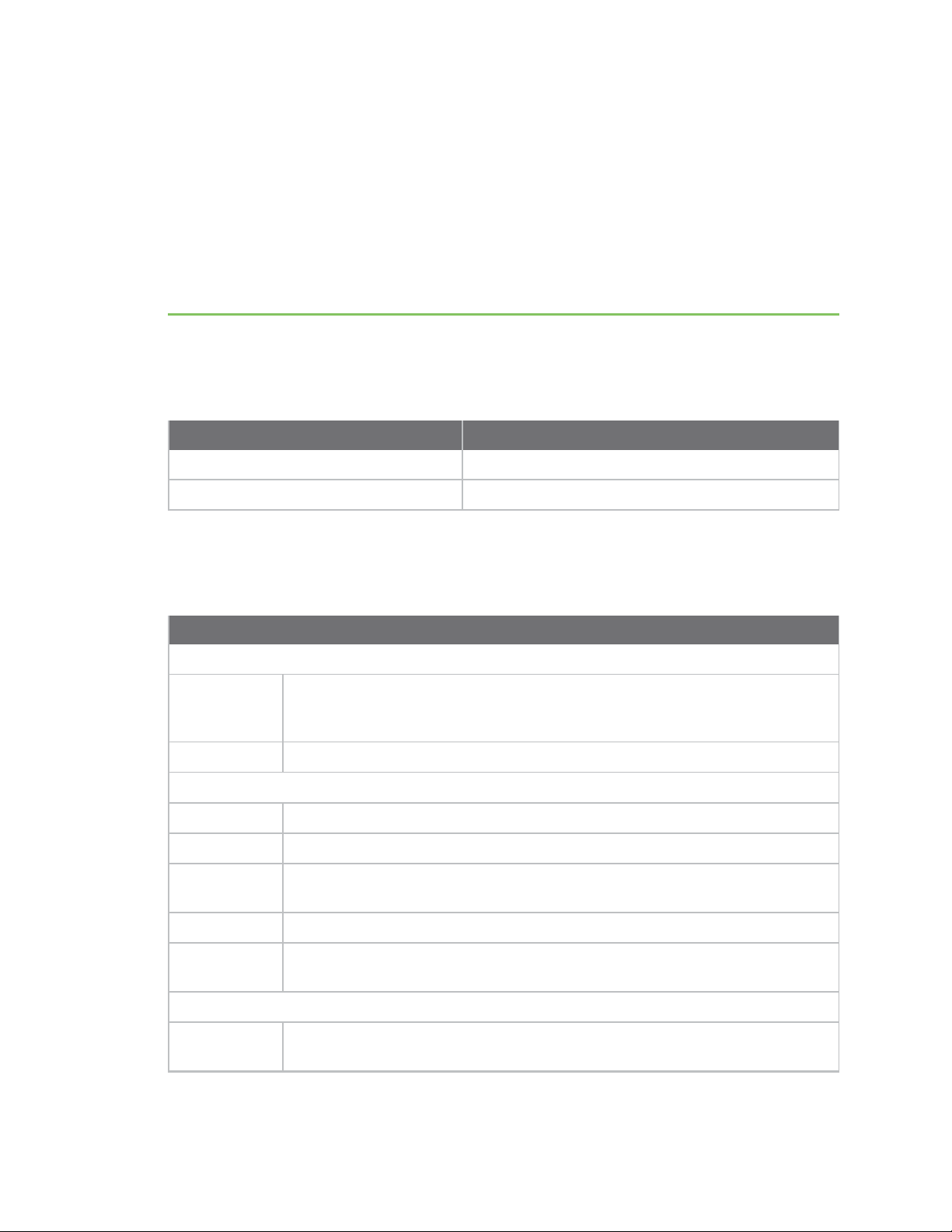
Maximum power and frequency bands
This section contains the maximum power and frequency bands for Connect Sensor.
Maximum power Associated frequencies
2 W Cellular 850 and 900 MHz bands
1 W Cellular 1800 and 1900 MHz bands
Connect Sensor product specifications
The following table provides a summary of general product specifications for Connect Sensor.
Specifications
Management
Configuration
and
management
Protocol TCP
Power
Battery 7.2V, 14 Ah, Lithium Thionyl Chloride, non-rechargeable, replaceable
Battery life
Battery self
discharge
Battery use -35°C ≤ Tamb ≤ 60°C ambient temperature range
External power
requirement
Environmental
Operating
temperature
Remote Manager
2 to 3 years (when following guidelines in Battery life)
up to 1%/year if stored at +30˚ C
8 VDC to 30 VDC at 1A
-35˚ C to +70˚ C
/Local USB to Serial CLI Protocol
Digi Connect® Sensor User Guide
24
Page 25
Technical specifications Cell modem transmit (TX) output power
Specifications
Storage
temperature
Relative
humidity
Ingress
Protection (IP)
rating
Physical
Dimensions
(L x W x H)
Weight 1.25 lbs
LEDs Bluetooth®, Sensor reading, Cellular, Battery
Enclosure
material
Enclosure
rating
-40˚ C to +85˚ C
90% (Non-condensing after 90%)
IP66
Note IP66 is for Class I Division 2 hazardous locations and ordinary locations only.
For more information on ATEXinstallation requirements, see ATEX requirements.
15.2 cm x 11.4 cm x 7.6 cm (6.0 in x 4.5 in x 3 in)
10% fiberglass reinforced polycarbonate
NEMA Type 4, 4X, 6, and 6P
UL 94 V-0
Cell modem transmit (TX) output power
Modem Band Power Class
HE910-D GSM 850 / 900 4 (2W)
DCS1800 / PCS 1900 1 (1W)
EDGE, 850/900 MHz E2 (0.5W)
EDGE, 1800/1900 MHz Class E2 (0.4W)
WCDMA FDD B1, B2, B4, B5, B8 Class 3 (0.25W)
LE910-NA1 LTEAll Bands Class 3 (0.2W)
WCDMA All Bands Class 3 (0.25W)
LE910-SV1 LTEAll Bands Class 3 (0.2W)
Digi Connect® Sensor User Guide
25
Page 26
Hardware
Battery inspection
CAUTION! This product contains a lithium metal battery. Prior to installation, the
battery should be inspected for any signs of damage. If the battery appears to be
damaged or is dropped during installation, do not use the battery and dispose of it
properly.
Please contact Digi Technical Support at 952-912-3444 or Tech.support@digi.com to order a
replacement battery.
The MSDS (Material Safety Data Sheet) for the battery can be found at
www.digi.com/documentation/ConnectSensor.
Battery life
Connect Sensor uses sleep and wake modes to manage power use. The device wakes only for sensor
readings and sending reports to Remote Manager. It is in sleep mode at all other times to maintain
low power consumption.
The battery will last 2 to 3 years in these conditions:
n Adequate cellular network coverage where Connect Sensor is installed
n Connect Sensor sends reports to Remote Manager a maximum of two times a day
n Connect Sensor is not powering high-current sensors with long read delays
The temperature at the device's location also affects the battery. Battery power is used more quickly
in a cold environment than in a warm environment. A battery in a device located where the
temperature is consistently 20° F will not last as long as a battery in a device located where the
temperature is consistently 80° F.
Extend battery life by scheduling less frequent sensor readings and reports. Scheduling more frequent
sensor readings and reports may shorten the battery life to less than 2 years.
Note When using the Continuous Monitoring feature, it is recommended that you use an external
power source rather than relying on the battery within Connect Sensor. See CSENSE Continuous
Monitoring power source for more information.
Battery percentage ranges and replacement
When the battery life percentage is above 30%, the battery has enough power to power the device,
and the device will function as expected.
Digi Connect® Sensor User Guide
26
Page 27

Hardware Battery percentage and external power
When the battery life percentage drops below 30%, the battery power is low and, depending on the
conditions in which the device is operating, may cease to power the device. To ensure that readings
continue as expected, it is recommended that you change the battery when the battery percentage
decreases to 30%. See Battery replacement.
You can view the battery life percentage in Remote Manager. See View battery life for a device in
Remote Manager.
Battery passivization
Unused lithium batteries that have been in storage acquire a state of passivization that can cause the
battery to report a low battery percentage for a time after initial installation. As the device uses the
battery, the passivization is removed and the battery percentage increases to a maximum of 90 100% (depending on the temperature). The passivization removal process could take a week or more,
if the number of times Connect Sensor wakes to take sensor readings and send reports to Remote
Manager is once per day or less.
Note Passivization may never be removed if the device sends reports to Remote Manager too
infrequently.
Battery percentage and external power
The device is powered by either external power connected to the device, or by an internal battery that
is connected to the device. The device is not powered by both power sources at the same time.
You can view the battery life percentage for a device in Remote Manager. See View battery life for a
device in Remote Manager. The battery life percentage depends on whether the device is using the
external power source or the battery.
n If the device is using the external power source and the battery is connected to the device,
then the battery life is 100%. This will occur whether the battery has any battery life remaining
or is dead.
n If the device is using the external power source and the battery is not connected to the device,
then the battery life is 0%.
n If the device is not using external power and the device is using the battery, the actual battery
life percentage displays, and is a percentage other than 100% or 0%.
CSENSE Continuous Monitoring power source
For some customers, the scheduling paradigm of the standard Connect Sensor offering is inadequate.
Digi offers an alternate firmware image that trades alarm reactivity for power consumption. The
CSENSE Continuous Monitoring firmware image can be downloaded and installed on a Connect
Sensor.
When using the Continuous Monitoring feature, Connect Sensor never sleeps. For best performance
and ease of use it is recommended that you use an external power source rather than relying on the
battery within Connect Sensor. If the battery is used, the battery life is significantly reduced. The
Connect Sensor battery can be used as a short-term battery backup if the external power source fails.
For more information about the Continuous Monitoring feature, see CSENSE Continuous Monitoring
firmware.
Digi Connect® Sensor User Guide
27
Page 28

Hardware Connect Sensor hardware replacement
Connect Sensor hardware replacement
The Connect Sensor hardware can be replaced with Connect Sensor+ hardware. Additional external
device monitoring features are available with Connect Sensor+ hardware:
n Modbus protocol
Digi Connect® Sensor User Guide
28
Page 29

Firmware
This section includes information about the Connect Sensor firmware options that are available in
addition to the standard firmware. These firmware options provide additional features. Note that
these firmware options contain all of the features in the standard Connect Sensor firmware in
addition to the features available in the firmware option you select.
If you want to use any of the optional features, you must upgrade from the standard Connect Sensor
firmware to the firmware variant that includes those features. The firmware upgrade can happen only
when Connect Sensor is awake and connected to Remote Manager. Any firmware upgrades,
configuration changes, or commands that have been added to a schedule in Remote Manager are
pushed to Connect Sensor at that time. If you need to upgrade the firmware before a scheduled push
from Connect Sensor, you can physically wake the Connect Sensor device to force a connection
between Connect Sensor and Remote Manager. For information on how to update the firmware, see
Firmware updates.
CSENSE Continuous Monitoring firmware
Note It is strongly recommended that an external power source for the Connect Sensor device is used
with continuous monitoring.
For some customers, the scheduling paradigm of the standard Connect Sensor offering is inadequate.
With continuous monitoring, Connect Sensor can constantly monitor sensors for an alarm by
continually sampling sensor data. This enables Connect Sensor to find alarms faster, and to not miss
any alarms that may have occurred between scheduled sensor readings.
The Connect Sensor device should be configured to specify a buffer time range for before and after an
alarm occurs. When an alarm occurs, Connect Sensor continues to sample data until the time limit of
the buffer is reached. When the buffer time limit is reached, the following information is pushed to
Remote Manager:
n Sample data in the buffer for the time range specified
n Alarm information
n Information from a scheduled reading stored in the device's memory
In addition to continuous monitoring, scheduled sensor readings still occur, and that data is stored in
the Connect Sensor memory.
n If a sensor alarm occurs, the data samples taken during the buffer time range plus any other
diagnostic information stored in the device's memory is pushed when the buffer time range is
reached.
n If an alarm doesn't occur between scheduled pushes, the information from a scheduled reading
stored in the device's memory is pushed to Remote Manager as scheduled.
Digi Connect® Sensor User Guide
29
Page 30

Firmware CSENSE Continuous Monitoring firmware
Continuous monitoring can occur simultaneously for up to five inputs: four analog and 1 digital.
n Analog 4-20mA Current Loop 1 or Analog Voltage Input 1
n Analog 4-20mA Current Loop 2 or Analog Voltage Input 2
n Analog 4-20mA Current Loop 3 or Analog Voltage Input 3
n Analog 4-20mA Current Loop 4 or Analog Voltage Input 4
n Digital Input
When using this feature, Connect Sensor never sleeps. For best performance and ease of use it is
recommended that you use an external power source rather than relying on the battery within
Connect Sensor. The Connect Sensor battery can be used as a battery backup if the external power
source fails.
Enable CSENSEContinuous Monitoring
Follow these steps to enable and configure continuous monitoring.
1. Upgrade to the CSENSE Continuous Monitoring firmware. For upgrade information, see
Firmware updates.
2. Enable the continuous monitoring feature on an Analog 4-20mA Current Loop, Analog Voltage
Input, or a Digital Input. For information, see Enable continuous monitoring on analog input or
Enable continuous monitoring on digital input.
3. Configure the buffer time range for all sensors using continuous monitoring to ensure the
desired amount of data is stored when an alarm occurs. For information, see Configure the
buffer time for continuous monitoring.
Enable continuous monitoring on digital input
Note The Connect Sensor firmware must be upgraded before continuous monitoring can be enabled
on the analog or digital input. For information, see CSENSE Continuous Monitoring firmware.
1. Follow the standard process to configure a digital input. For instructions, see Enable and
configure a digital input.
2. The digital input must be enabled. Verify that the Interface Enable (ena) option is set to On.
3. Verify that the Continuous Monitoring Enable (mon) option is set to On.
4. Click Save.
5. Apply the configuration changes:
a. Click Save > Schedule. The Save Device Properties dialog appears.
b. Select a scheduling option. See Schedule options.
Note The Recurring option does not work with the Connect Sensor device.
c. Click Schedule. Connect Sensor downloads and applies configuration changes the
next time it connects to Remote Manager.
Digi Connect® Sensor User Guide
30
Page 31

Firmware CSENSE Continuous Monitoring firmware
6. Configure the buffer time for the sensor to ensure the desired amount of data is stored when
an alarm occurs. For information, see Configure the buffer time for continuous monitoring.
Enable continuous monitoring on analog input
Note The Connect Sensor firmware must be upgraded before continuous monitoring can be enabled
on the analog or digital input. For information, see CSENSE Continuous Monitoring firmware.
1. Follow the standard process to configure an Analog 4-20mA Current Loop or Analog Voltage
Input. For instructions, see Enable and configure analog inputs.
2. The analog input must be enabled. Verify that the Interface Enable (ena) option is set to On.
3. Verify that the Continuous Monitoring Enable (mon) option is set to On.
4. Click Save.
5. Apply the configuration changes:
a. Click Save > Schedule. The Save Device Properties dialog appears.
b. Select a scheduling option. See Schedule options.
Note The Recurring option does not work with the Connect Sensor device.
c. Click Schedule. Connect Sensor downloads and applies configuration changes the
next time it connects to Remote Manager.
6. Configure the buffer time for the sensor to ensure the desired amount of data is stored when
an alarm occurs. For information, see Configure the buffer time for continuous monitoring.
Configure the buffer time for continuous monitoring
To ensure the desired amount of data is stored when an alarm occurs, you should configure the buffer
time range for the sensor.
1. Sign in to Remote Manager.
2. Click Device Management > Devices.
3. Double-click on the Connect Sensor device you want to configure.
4. Expand the Configuration menu.
5. Click Device Settings.
6. Configure the buffer time range for before and after the alarm event. The time is measured in
seconds.
a. In the Buffer Sensor Data Before Alarm field, select the number of seconds of
sample data that occurred before the alarm that should be saved and pushed.
b. In the Buffer Sensor Data After Alarm field, select the number of seconds of
sample data that occurred after the alarm that should be saved and pushed.
7. Apply the configuration changes:
Digi Connect® Sensor User Guide
31
Page 32

Firmware CSENSE Continuous Monitoring firmware
a. Click Save > Schedule. The Save Device Properties dialog appears.
b. Select a scheduling option. See Schedule options.
Note The Recurring option does not work with the Connect Sensor device.
c. Click Schedule. Connect Sensor downloads and applies configuration changes the
next time it connects to Remote Manager.
Digi Connect® Sensor User Guide
32
Page 33

Configure pins and protocols
Before you begin configuring the analog and digital pins, and the Modbus protocols, make sure you
have completed the following steps:
n Configure the cellular connection
n Check the cellular connection
n Wire the I/O sensors
n Add a device to Digi Remote Manager
After completing those steps, you can use Remote Manager with Connect Sensor to remotely
configure sensors, schedule sensor readings and reports, review reports (sensor and device data), and
manage the device. Connect Sensor automaticallydetects the device version and provides support for
its configuration within the available options in Remote Manager.
You can also configure Connect Sensor to send alarm reports when an alarm condition occurs in an
environment. Alarm reports are separate from scheduled reports. Use alarm reports to communicate
changes in your environment and the device, including:
n Low and high sensor input values
n Rapid changes in sensor input values
n Battery life
See Configure pins and protocols, Configure battery life percentage alarms, and View device
information.
Enable and configure analog inputs
Connect Sensor has four analog inputs, each of which you can configure as either a 4-20 mA current
loop or a voltage input. For details about the configuration options, see Analog Current Loop Input and
Voltage Input option definitions.
To set analog input options:
1. Sign in to Remote Manager.
2. Click Device Management > Devices tab.
3. Double-click the Connect Sensor device you want to configure.
4. Expand the Configuration menu.
Digi Connect® Sensor User Guide
33
Page 34

Configure pins and protocols Enable and configure analog power outputs
5. Select the analog input for your sensor:
n Analog: 4-20mA Current Loop 1-4
n Analog: Voltage Input 1-4
Note Configure each analog input as either a current loop or a voltage input, not both. For
example, if you enable Analog: 4-20mA Current Loop 1, make sure you disable Analog: Voltage
Input 1.
6. Enable the input by selecting On for Interface Enable.
7. Select On for the alarms you want to enable and enter an appropriate value for each threshold
that you enabled. For more information, see Alarms.
8. Enter a value for Hysteresis to prevent multiple alarms when the sensor input value is near a
high or low threshold. For more information, see Hysteresis.
9. Enter a user-friendly name that describes the sensor in the Sensor Description field.
10. Enter the unit of measurement type, such as inches, that you are using for your application in
the Custom Scaled Sample Unit field.
11. Enter the sensor manufacturer's values for y1 and y2 in the Custom Scaled Sample Value
fields. For more information about the Custom Scaled fields, see Custom scaled sensor values.
12. Enable the oversampling feature, if desired. For more information about this feature, see
Oversampling.
a. From the Oversampling (ovs) list box, select the option that describes the desired
value for the sampled data: Average, Minimum, or Maximum.
b. In the Oversampling Inter-sample Delay field, specify the time interval between
readings. The time is measured in milliseconds.
c. In the Oversampling Number Samples field, specify the number of data samples
that must be taken.
13. Apply the configuration changes:
a. Click Save > Schedule. The Save Device Properties dialog appears.
b. Select a scheduling option. See Schedule options.
Note The Recurring option does not work with the Connect Sensor device.
c. Click Schedule. Connect Sensor downloads and applies configuration changes the
next time it connects to Remote Manager.
Enable and configure analog power outputs
Note Powering sensors reduces battery life.
Enable and configure the power output options when you use Connect Sensor to power the analog
sensors.
Digi Connect® Sensor User Guide
34
Page 35

Configure pins and protocols Enable and configure a digital input
Each of the four analog inputs also has four corresponding power outputs to power sensors. The
analog power outputs work independently—each one powers only its corresponding analog input.
For example:
n Analog:Power Output 1 powers either Analog: 4-20mA Current Loop 1 or Analog:Voltage Input
1.
n Analog:Power Output 2 powers either Analog: 4-20mA Current Loop 2 or Analog:Voltage Input
2, and so on.
When Connect Sensor powers multiple sensors, it powers only one sensor at a time for each sensor
reading. This also allows you to set different voltage ranges for each power output. For example, you
can set Analog:Power Output 1 to 3.3 V and Analog:Power Output 2 to 15 V.
For details about the configuration options, see Analog Power, Digital Power, and Serial Output option
definitions.
To set analog power output options in in Remote Manager:
1. Sign in to Remote Manager.
2. Click Device Management > Devices tab.
3. Double-click the Connect Sensor device you want to configure.
4. Expand the Configuration menu.
5. Click Analog:Power Output and select the power output that corresponds to your analog
input.
6. Enable the output by selecting On for Power Output Enable.
7. Select the appropriate voltage Output Level for your power output. Refer to the manufacturer
specifications for the sensor.
8. Enter the appropriate Read Delay that your sensor needs to stabilize before reading the
sensor input value. Refer to the manufacturer specifications for the sensor.
For example, a sensor may need 7 seconds to power on and stabilize before it can get an
accurate reading.
Note A higher read delay keeps the device powered on longer, which reduces battery life.
9. Apply the configuration changes:
a. Click Save > Schedule. The Save Device Properties dialog appears.
b. Select a scheduling option. See Schedule options.
Note The Recurring option does not work with the Connect Sensor device.
c. Click Schedule. Connect Sensor downloads and applies configuration changes the
next time it connects to Remote Manager.
Enable and configure a digital input
Connect Sensor has one digital I/O pin. You can configure the pin as a digital input, pulse counter, or
digital output, but not more than one I/O function simultaneously.
Digi Connect® Sensor User Guide
35
Page 36

Configure pins and protocols Enable and configure a digital pulse counter
In addition to the standard alarm and user-friendly name settings, the digital input options include
rising edge wake, falling edge wake, and a pull-up resistor.
For details about the configuration options, see Digital Input option definitions.
To configure digital input options:
1. Sign in to Remote Manager.
2. Click Device Management > Devices tab.
3. Double-click the Connect Sensor device you want to configure.
4. Expand the Configuration menu.
5. Select Digital: Input.
6. Select On for Interface Enable and disable the interface for all other digital I/O settings:
n Digital: Output >Interface Enable: Off
n Digital: Pulse Counter >Interface Enable:Off
7. Select On for the alarms you want to enable.
8. Select On for Rising Edge Wake and Falling Edge Wake to enable them.
9. Select On for Enable pullup when your application requires it.
10. Enter a user-friendly name for the sensor in the Sensor Description field.
11. Apply the configuration changes:
a. Click Save > Schedule. The Save Device Properties dialog appears.
b. Select a scheduling option. See Schedule options.
Note The Recurring option does not work with the Connect Sensor device.
c. Click Schedule. Connect Sensor downloads and applies configuration changes the
next time it connects to Remote Manager.
Enable and configure a digital pulse counter
Connect Sensor has one digital I/O pin. You can configure the pin as a digital input, pulse counter, or
digital output, but not more than one I/O function simultaneously.
When using a digital pulse counter, Connect Sensor continues to count pulses during sleep cycles and
reports them to Remote Manager during normal reporting intervals.
For example, if Connect Sensor reports every hour, the sensor counts pulses during each hour
Connect Sensor is in sleep mode. At the end of each hour, Connect Sensor wakes and reports the total
pulse count for that hour to Remote Manager. The pulse counter resets to zero after each wake cycle
and stores the values until the next reporting interval.
For details about the configuration options, see Digital Pulse Counter option definitions.
To set digital pulse counter options:
1. Sign in to Remote Manager.
2. Click Device Management > Devices tab.
3. Double-click the Connect Sensor device you want to configure.
4. Expand the Configuration menu.
Digi Connect® Sensor User Guide
36
Page 37

Configure pins and protocols Enable and configure a digital output
5. Click Digital: Pulse Counter.
6. Select On for Interface Enable and disable the interface for all other digital I/O settings:
n Digital: Input > Interface Enable: Off
n Digital: Output >Interface Enable: Off
7. Select On for the alarms you want to enable and enter an appropriate value for each threshold
that you enabled.
8. Enter a value for Hysteresis to prevent multiple alarms when the sensor input value is near a
high or low threshold.
9. Select On for Enable pullup when your application requires it.
10. Enter a user-friendly name for the sensor in the Sensor Description field.
11. Enter the unit of measurement type, such as inches, that you are using for your application in
the Custom Scaled Sample Unit field.
12. Enter the sensor manufacturer's values for y1 and y2 in the Custom Scaled Sample Value
fields. For more information about the Custom Scaled fields, see Custom scaled sensor values.
13. Apply the configuration changes:
a. Click Save > Schedule. The Save Device Properties dialog appears.
b. Select a scheduling option. See Schedule options.
Note The Recurring option does not work with the Connect Sensor device.
c. Click Schedule. Connect Sensor downloads and applies configuration changes the
next time it connects to Remote Manager.
Enable and configure a digital output
Connect Sensor has one digital I/O pin. You can configure the pin as a digital input, pulse counter, or
digital output, but not more than one I/O function simultaneously. Use Remote Manager to control a
digital output level and enable an internal pull-up resistor. For details about the configuration options,
see Digital Output option definitions.
To set digital output options:
1. Sign in to Remote Manager.
2. Click Device Management > Devices tab.
3. Double-click the Connect Sensor device you want to configure.
4. Expand the Configuration menu.
5. Select Digital: Output.
6. Select On for Interface Enable and disable the interface for all other digital I/O settings:
n Digital: Input > Interface Enable: Off
n Digital: Pulse Counter >Interface Enable:Off
7. Select the appropriate Output Level for your digital output. Refer to the manufacturer
specifications for the sensor.
Digi Connect® Sensor User Guide
37
Page 38

Configure pins and protocols Enable and configure a digital power output
8. Select the appropriate Toggle Output on option If you want to toggle the digital output on a
selected alarm. For more detailed information, see Toggle digital output on alarm.
9. Select On for Enable pullup when your application requires it.
10. Enter a user-friendly name for the sensor in the Sensor Description field.
11. Apply the configuration changes:
a. Click Save > Schedule. The Save Device Properties dialog appears.
b. Select a scheduling option. See Schedule options.
Note The Recurring option does not work with the Connect Sensor device.
c. Click Schedule. Connect Sensor downloads and applies configuration changes the
next time it connects to Remote Manager.
Enable and configure a digital power output
Note Powering sensors reduces battery life.
Configure the digital power output options when you use Connect Sensor to power an external device.
For details about the configuration options, see Analog Power, Digital Power, and Serial Output option
definitions.
To set digital power output options in Remote Manager:
1. Sign in to Remote Manager.
2. Click Device Management > Devices tab.
3. Double-click the Connect Sensor device you want to configure.
4. Expand the Configuration menu.
5. Select Digital: Power Output.
6. Enable the output by selecting On for Power Output Enable.
7. Select the appropriate voltage Output Level for your power output. Refer to the manufacturer
specifications for the sensor.
8. Enter the appropriate Read Delay that your sensor needs to stabilize before reading the
sensor input value. Refer to the manufacturer specifications for the sensor.
For example, a sensor may need 7 seconds to power on and stabilize before it can get an
accurate reading.
Note A higher read delay keeps the device powered on longer, which reduces battery life.
9. Apply the configuration changes:
a. Click Save > Schedule. The Save Device Properties dialog appears.
b. Select a scheduling option. See Schedule options.
Note The Recurring option does not work with the Connect Sensor device.
Digi Connect® Sensor User Guide
38
Page 39

Configure pins and protocols Enable and configure the Modbus protocol
c. Click Schedule. Connect Sensor downloads and applies configuration changes the
next time it connects to Remote Manager.
Enable and configure the Modbus protocol
Modbus is an industrial automation protocol used for sending and receiving digital information across
a single, external RS-485 serial bus.
Note The Modbus protocol is available only with Connect Sensor+ hardware.
The Modbus protocol allows Connect Sensor to collect remote diagnostic information from a Modbusenabled sensor as well as alert a user remotely if the sensor malfunctions. You can configure Connect
Sensor to collect remote diagnostic information from up to four Modbus-enabled sensors.
The Modbus protocol uses the serial pins on the I/O terminal block in Connect Sensor. The
configuration settings specified in the Modbus Protocol Settings page in Remote Manager must
exactly match the Modbus protocol settings on the external sensor device(s). The configuration
includes a list of variables, which specify the locations on the Modbus device that the Connect Sensor
should read to collect diagnostic information.
You can also choose to enable the Modbus protocol alarm option. This ensures that when an error
occurs with the Modbus-enabled sensor, error information is pushed to Remote Manager without
waiting for the next scheduled push.
You can review diagnostic information from the Modbus-enabled sensor in the Data Services tab in
Remote Manager. For more information about reviewing Modbus information in the data stream, see
Modbus (modb1) data stream definitions.
1. Sign in to Remote Manager.
2. Click Device Management > Devices tab.
3. Double-click the Connect Sensor device you want to configure.
4. Expand the Configuration menu.
5. Click Modbus Protocol Settings.
6. For the Protocol Enable (ena) field, select the On option.
7. Determine whether error information should be pushed immediately. For the Device Status
Alarm Mask (aem) option:
n Select the On option if error information should be pushed immediately.
n Select the Off option if error information should be pushed with the next scheduled
push.
8. The following settings must match the configuration of the external sensor device. Select the
appropriate option from the list box.
n Serial framing mode (mode)
n Serial baud rate (baud)
n Serial data bits (dbt)
n Serial stop bits (sbt)
n Serial parity (par)
Digi Connect® Sensor User Guide
39
Page 40

Configure pins and protocols Enable and configure the Modbus protocol
9. For each Modbus sensor that you want to monitor, you can specify the station address and
then include a list of variable addresses. The items in the list must be separated by a comma
without spaces. The list is limited to 63 characters, which allows for 8 to 10 variables in a list.
For more information about identifying Modbus stations and locations, see Modbus station
addresses and locations.
a. In the Station1: Slave Address (saddr1) field, select the station address.
b. In the Station 1: Variable list (vars1) field, enter the list of variable addresses.
c. Repeat this process for any additional stations. You can specify up to four stations.
10. Apply the configuration changes:
a. Click Save > Schedule. The Save Device Properties dialog appears.
b. Select a scheduling option. See Schedule options.
Note The Recurring option does not work with the Connect Sensor device.
c. Click Schedule. Connect Sensor downloads and applies configuration changes the
next time it connects to Remote Manager.
11. If Connect Sensor is providing power to the Modbus device, you must enable the serial power
output. For instructions, see Enable and configure a serial power output.
Digi Connect® Sensor User Guide
40
Page 41

Configure pins and protocols Enable and configure the Modbus protocol
If the external sensor device has an alternate power source, you can skip this step.
Enable and configure a serial power output
This section describes how to configure serial power. Note that powering sensors reduces battery life;
to reduce unnecessary battery consumption, only wake the device when needed.
Note The serial power output option is available only with Connect Sensor+, and is used only with a
Modbus device.
If Connect Sensor is providing power to the Modbus device, you must enable the serial power output.
To set serial power output options in Remote Manager:
1. Sign in to Remote Manager.
2. Click Device Management > Devices tab.
3. Double-click the Connect Sensor device you want to configure.
4. Expand the Configuration menu.
5. Select Serial: Power Output.
6. Enable the output by selecting On for Power Output Enable.
7. Select the appropriate voltage Output Level for your power output. Refer to the manufacturer
specifications for the sensor.
8. Enter the appropriate Read Delay that your sensor needs to stabilize before reading the
sensor input value. Refer to the manufacturer specifications for the sensor. For example, a
sensor may need 7 seconds to power on and stabilize before it can get an accurate reading.
Note A higher read delay keeps the device powered on longer, which reduces battery life.
9. Apply the configuration changes:
a. Click Save > Schedule. The Save Device Properties dialog appears.
b. Select a scheduling option. See Schedule options.
Note The Recurring option does not work with the Connect Sensor device.
c. Click Schedule. Connect Sensor downloads and applies configuration changes the
next time it connects to Remote Manager.
Modbus station addresses and locations
In Modbus, a station address acts as a unique identifier for the external sensor device. A station
address is assigned when the external sensor device is configured and installed. Multiple stations
listen to the bus and can respond only to the commands that match their unique station address.
Connect Sensor acts as a master to the slave station addresses. All Modbus devices connected to
Connect Sensor must have the exact same serial configuration.
In the Connect Sensor configuration, you can specify a list of variable addresses for each station
address. The variable addresses identify the values that should be pulled from each station device.
If Connect Sensor is configured to read a variable that is unsupported by a Modbus station, no data
sample is stored.
Digi Connect® Sensor User Guide
41
Page 42

Configure pins and protocols Enable and configure the Modbus protocol
Finding the Modbus address
A Modbus variable address includes a combination of the reading category, the logical address of the
information, and the interpretation method. Together these create a variable address that can be
added to a variable list in the Connect Sensor configuration.
Step 1: Determine the reading category
The reading category is the single digit prefix of the variable address. Each variable type has a unique
prefix.
Modbus variable type Number of bits Prefix value
Coil 1 0
Discrete input 1 1
Input register 16 3
Holding register 16 4
Step 2: Determine the logical address
Many Modbus device specifications list variables using a 0-based physical address. Since Modbus uses
a 1-based logical address, the logical address is calculated by adding one to the physical address. The
logical address must have either four or five digits, padded on the left by zeroes if required.
For each configured station address, you can configure a corresponding variable list. The variable list
is limited to 63 characters, which limits the number of variables to between 8 and 10.
A variable address can be either 5 or 6 decimal digits in length.
Five decimal digits:
00001 - 09999 Coils: physical addresses 0 - 9998
10001 - 19999 Discrete inputs: physical addresses 0 - 9998
30001 - 39999 Input registers: physical addresses 0 - 9998
40001 - 49999 Holding registers: physical addresses 0 - 9998
Six decimal digits:
00001 - 065536 Coils: physical addresses 0 - 65535
10001 - 165536 Discrete inputs: physical addresses 0 - 65535
30001 - 365536 Input registers: physical addresses 0 - 65535
40001 - 465536 Holding registers: physical addresses 0 - 65535
Step 3: Determine the interpretation method
Generally, a single-bit value is interpreted as either 0 or 1, and a 16-bit value is interpreted as an
integer between 0 and 65535. These are the default interpretations for the four categories, and no
extra specification is required.
Digi Connect® Sensor User Guide
42
Page 43

Configure pins and protocols About analog and digital input options
Some Modbus devices, however, specify that a pair of consecutive 16-bit registers should be combined
and the 32-bits be interpreted as an IEEE 754 floating point value instead. To indicate this, the
Connect Sensor variable address requires a suffix of either ‘f’ or ‘F’:
If the 32-bit value can be represented as DCBA, where D represents the most significant byte of the
value, and A represents the least significant byte of the value, two floating point encodings are
supported as follows:
f IEEE 754 floating point value with bytes in the following order: B A D C
F IEEE 754 floating point value with bytes in the following order: D C B A
Examples
n If the device specification defines a simple holding register at physical address 4002, the prefix
is 4, the logical address is 4003, and there is no interpretation suffix. The combined logical
address is 44003.
n If the device specification defines a coil at physical address 17, the prefix is 0, the logical
address is 0018 (zero padded), and there is no interpretation suffix. The combined logical
address is 00018.
n If the device specification defines an input register at physical address 7002 that is 32-bit
floating point value with bytes presented in D C B A order, the prefix is 3, the logical address is
7003, and the interpretation suffix is ‘F’. The combined logical address is 37003F.
About analog and digital input options
Use Remote Manager to:
n Enable each of the analog and digital inputs and configure their options to get sensor data in
Remote Manager. For more information, see Enable and configure analog inputs or Enable and
configure a digital input.
n Alarms: Configure alarms for each sensor to alert you when there are sudden changes in your
industrial environment. For additional information, see Alarms and Hysteresis.
n Custom Scaling: Use custom scaled sensor values to convert raw data into custom units that
are meaningful to your application. For additional information, see Custom scaled sensor
values.
n Oversampling: Configure oversampling to increase the precision of a data sample collected at
a scheduled reading by reading multiple samples. For additional information, see
Oversampling.
Alarms
Use alarms to send reports to Remote Manager when unusual changes occur in sensor values. Alarm
reports are sent when a sensor reaches an alarm value during a sensor reading, even if it is between
reporting intervals.
Connect Sensor sends alarm reports as follows:
Digi Connect® Sensor User Guide
43
Page 44

Configure pins and protocols About analog and digital input options
n High alarm: Sends an alarm report when the input value is greater than the high threshold.
n Low alarm:Sends an alarm report when the input value is less than the low threshold.
n Delta high alarm:Sends an alarm report when the input value increases too much between
two consecutive readings.
n Delta low alarm:Sends an alarm report when the input value decreases too much between
two consecutive readings.
n Rising edge: Sends an alarm report when the device wakes on a digital input change from low
voltage to high voltage.
n Falling edge: Sends an alarm report when the device wakes on a digital input change from
high voltage to low voltage.
For example, with high alarms enabled and configured, Connect Sensor is configured to read sensor
input values every hour and scheduled to send reports twice every day, at 8:00 and 20:00. An input
value suddenly reaches its high threshold at 11:00. When Connect Sensor wakes at 11:00 to take a
reading, it sends a high alarm report to Remote Manager.
Alarms are available for the following:
n Analog: 4-20mA Current Loop Input
n Analog: Voltage Input
n Digital: Input
n Digital: Pulse Counter
For Connect Sensor+, an alarm is also available for the following:
n Modbus protocol: Enable and configure the Modbus protocol
Hysteresis
Sensor values may sometimes fluctuate during an alarm condition, which causes Connect Sensor to
send multiple alarm reports.
Hysteresis works with the high and low alarm thresholds to tell the device when to keep an alarm on
without sending additional alarm reports, or when to shut off an alarm. Use this to avoid repeated
alarms during common sensor input value fluctuations.
For example, a pressure sensor input value increases to the high threshold and the device sends a
high alarm report. However, the pressure sensor input value continues to increase and decrease
repeatedly between normal and high thresholds during this alarm condition. If you have not set a
hysteresis range, the Connect Sensor device sends an alarm report every time the sensor input value
reaches the high threshold.
The following are examples of how high and low hysteresis works with a voltage input:
n High hysteresis: If your high threshold is 10 volts and your hysteresis value is 2 volts, then
your high alarm hysteresis is 8 volts. This means that the alarm turns on when the sensor input
value reaches 10 volts and remains on if the sensor input value stays above 8 volts. No
additional alarm reports are sent during this alarm condition. The alarm turns off when the
sensor input value falls below 8 volts.
Digi Connect® Sensor User Guide
44
Page 45

Configure pins and protocols About analog and digital input options
n Low hysteresis: If your low alarm threshold is 2 volts and the hysteresis value is 3 volts, then
your low alarm hysteresis is 5 volts. This means that the alarm turns on when the sensor input
value reaches 2 volts and remains on if the sensor input value stays below 5 volts. No
additional alarm reports are sent during this alarm condition. The alarm turns off when the
sensor input value rises above 5 volts.
Setting the hysteresis threshold to 0 (zero) causes Connect Sensor to send an alarm report every time
the sensor input value exceeds a high or low alarm threshold.
Note Setting the hysteresis threshold to 0 (zero) may cause excessive data usage and reduce battery
life.
Custom scaled sensor values
Connect Sensor reads raw sensor values in milliamps (mA), volts, and pulses. Use the Custom Scaled
settings in Remote Manager to convert raw values for both analog inputs and the digital pulse counter
into meaningful values for your environment, such as when converting 4-20 mA current to liters or
pulses to amp hours.
Refer to the sensor's manufacturer specifications for details about conversion rates and calculations.
Analog input examples
In Remote Manager, both the current loop and voltage input settings use the following fields to
convert current or volts into meaningful values for your environment.
n Custom Scaled Sample Unit: Unit of measurement that you are converting to, such as liters,
watts, miles per hour, degrees, and so on.
n Custom Scaled Sample Value (y1): Point 1 custom value associated as follows:
l Current loop: 4 mA
l Voltage: 0 V
n Custom Scaled Sample Value (y2): Point 2 custom value associated as follows:
l Current loop: 20 mA
l Voltage: 10 V
Use the manufacturer specifications for your sensor to calculate the y1 and y2 values.
4-20 mA current loop input example
This example demonstrates how to determine y1 and y2 in liters for a 4-20 mA current loop input. This
graph is similar to what you find in sensor manufacturer's specifications.
Note When calculating values, there must be a linear relationship between y1 and y2. If the sensor's
measurements are not linear, the calculated values will not be accurate.
Digi Connect® Sensor User Guide
45
Page 46

Configure pins and protocols About analog and digital input options
The following image shows you enter this information in Remote Manager.
Voltage input example
This example demonstrates how to determine y1 and y2 in candles for a voltage input. This graph is
similar to what you find in sensor manufacturer's specifications.
Note When calculating values, there must be a linear relationship between y1 and y2. If the sensor's
measurements are not linear, the calculated values will not be accurate.
Digi Connect® Sensor User Guide
46
Page 47

Configure pins and protocols About analog and digital input options
The following image shows you enter this information in Remote Manager.
Digital pulse counter example
Using pulse counting, Custom Scaling Factor, Custom Scaled Sample Unit, and a time range, the
digital pulse counter provides the appropriate measurement for your environment. The following
equation shows how pulses are converted:
n Pulses betweenreportingintervals x Custom scaling factor (in CustomScaled Sample Unit) =
reported measurement
n Pulses between reporting intervals: Number of pulses between reporting intervals, which is
based on report settings in Remote Manager (see Configure device (report) settings).
n Custom scaling factor: Refer to your sensor's manufacturer specifications for this value.
n Custom scaled sample unit:Unit of measurement for your application.
n Reported measurement: Reported value in the unit of measurement for your application.
Digi Connect® Sensor User Guide
47
Page 48

Configure pins and protocols Schedule options
For example, we want to measure rainfall in inches using a rain gauge with a digital pulse counter. The
manufacturer specifications for our sensor state that 1 pulse equals 0.011 inches.
We configure Connect Sensor to send reports to Remote Manager every hour. Connect Sensor reads
100 pulses from 11:00 to 12:00.
100 (pulses) during one hour x 0.011 (inches) = 1.1 inches
The digital pulse counter device reports a rainfall amount of 1.1 inches between 11:00 and 12:00.
The following image shows how you would enter this example into the Digital: Pulse Counter settings
in Remote Manager.
Oversampling
The oversampling feature enables you to increase the precision of a data sample collected at a
scheduled reading by reading multiple samples. You can specify the number of samples that should be
read and the time interval between each reading. You can also specify how the data samples should
be manipulated to create the final data sample that is pushed: an average value of all of the samples,
the minimum value, or the maximum.
Oversampling can be enabled on all four Analog 4-20mA Current Loop and on all four Analog Voltage
inputs.
For example, oversampling is configured to discover the average value of 10 readings taken 70
milliseconds apart. Whenever Connect Sensor needs a value for that sensor, such as on a scheduled
wake, it actually reads the sensor 10 times, 70 milliseconds apart, averages those results, and uses
the averaged value as the sensor reading.
Note Reading a large number of data samples over a long interval reduces battery life.
Schedule options
You can schedule a configuration change to occur immediately or at a specified date and time in the
future.
Click Save > Schedule to access the Save Device Properties dialog.
Immediate
Apply changes during the next wake cycle.
Digi Connect® Sensor User Guide
48
Page 49

Configure pins and protocols Schedule options
1. Select Immediate.
2. Select the Schedule Offline check box. Queue upload occurs the next time this device
connects to Remote Manager.
3. Click Schedule.
One-Time
Apply changes on a specific date and time in the future.
1. Select One-Time.
2. Choose a date and time from the drop-down menus. The change is applied during the wake
cycle after the date and time you specify.
3. Select the Schedule Offline check box. Queue upload occurs the next time this device
connects to Remote Manager.
4. Click Schedule.
Recurring
The Recurring option does not work with the Connect Sensor device.
Digi Connect® Sensor User Guide
49
Page 50

Configure Connect Sensor device settings
You can configure Connect Sensor settings in Remote Manager.
n Configure cellular options
n Configure Remote Manager settings
n Configure battery life percentage alarms
n Configure internal temperature settings
n Configure local interface settings: CLIand Bluetooth
n Configure device (report) settings
Note The Connect Sensor battery can operate 2 to 3 years when you follow standard operating
conditions. Changes Connect Sensor device settings can affect battery life. For more information on
standard operating conditions, see Battery life.
Configure cellular options
You configured necessary cellular settings during the initial Connect Sensor setup. Use these options
to review the cellular configuration. Make changes to these settings only when instructed by your
cellular service provider and when you have physical access to the device. For details about these
options, see Cellular option definitions.
CAUTION! If you make changes to cellular settings that result in a disconnected device,
you must use the CLI to reconnect it to the cellular network; see Configure the cellular
connection. Using the CLIrequires physical access to the device.
To configure cellular options:
1. Sign in to Remote Manager.
2. Click Device Management > Devices tab.
3. Double-click the Connect Sensor device you want to configure.
4. Expand the Configuration menu.
5. Click Cellular Settings.
6. Enter an appropriate value for each cellular option.
7. Apply the configuration changes:
Digi Connect® Sensor User Guide
50
Page 51

Configure Connect Sensor device settings Configure Remote Manager settings
a. Click Save > Schedule. The Save Device Properties dialog appears.
b. Select a scheduling option. See Schedule options.
Note The Recurring option does not work with the Connect Sensor device.
c. Click Schedule. Connect Sensor downloads and applies configuration changes the
next time it connects to Remote Manager.
Configure Remote Manager settings
Remote Manager settings options for Connect Sensor are configured by default and require updates
only when instructed by Digi Technical Support. For details about these options, see Device Cloud
option definitions.
To configure Remote Manager options:
1. Sign in to Remote Manager.
2. Click Device Management > Devices tab.
3. Double-click the Connect Sensor device you want to configure.
4. Expand the Configuration menu.
5. Click Device Cloud Settings.
6. Enter appropriate values for each option.
7. Apply the configuration changes:
a. Click Save > Schedule. The Save Device Properties dialog appears.
b. Select a scheduling option. See Schedule options.
Note The Recurring option does not work with the Connect Sensor device.
c. Click Schedule. Connect Sensor downloads and applies configuration changes the
next time it connects to Remote Manager.
Configure battery life percentage alarms
Battery percentage is a measurement of the remaining life of a battery used in a Connect Sensor
device. This measurement gives you a data point for monitoring the health of the battery and
determining whether the battery should be replaced.
The battery percentage is calculated using an algorithm that considers current temperature
conditions, cell tower congestion, and how often the device wakes up to take sensor readings and
send reports to Remote Manager. See Battery life for more information about these considerations.
The battery percentage fluctuates, which is normal, and shows a trend over time as the battery
expends stored power. Locations with large temperature changes will cause corresponding battery
percentage fluctuations. For example, the temperature range in a desert environment can range from
0° F in the morning to 100° F in the evening in the same day. In this environment, the battery
percentage reading could be 40% in the morning and then 90% in the afternoon.
Digi Connect® Sensor User Guide
51
Page 52

Configure Connect Sensor device settings Configure battery life percentage alarms
Note If an external power source is used to power Connect Sensor and a battery is connected to the
device, the battery percentage is reported in Remote Manager as 100%.
Battery life alarm and alarm notification
Remote Manager has two battery life alarm methods that you can configure to alert you when the
battery life percentage falls below a specified threshold. The Global Alarm setting is configured by
default, and works with the battery indicator light on the device. You can also create an additional
battery life alarm that sends an email notification.
Global Alarm setting
The battery life percentage threshold for a device is configured in the Global Alarm Settings page by
default. This feature alerts you when the battery percentage falls below the specified threshold.
The battery indicator light on the device blinks in certain colors and patterns when the device wakes
to signify the battery status. When the battery percentage falls below the threshold, a battery alarm
data point is added to the data stream.
n Configure the global battery alarm for a device
n View battery information in a data stream
n Connect Sensor LEDs
Create a battery life alarm
You can create an alarm to monitor the battery life percentage for one specified Connect Sensor
device, or for all devices that have a battery. When the conditions of the alarm are met, the alarm is
fired and the alarm status changes to Fired in the alarm list.
If you have set up email notification, you will receive an email when the alarm fires.
n Create a battery life alarm for Connect Sensor devices
n Create an alarm notification
Create a battery life alarm for Connect Sensor devices
Within Remote Manager, you can create an alarm to monitor the battery life percentage in one
specific Connect Sensor device, or all devices that have a battery.
Note You cannot monitor a group of devices.
When the conditions of the alarm are met, the alarm is fired and the alarm status changes to Fired in
the alarm list on the Alarms page.
After you have created the alarm, you can set up email notification and receive an email when the
alarm fires.
In this example, an alarm is fired when the battery percentage drops below 30%, and automatically
resets when the battery percentage is greater than 40%.
1. Sign in to Remote Manager.
2. Click Device Management > Alarms.
3. Click Add. The Add Alarm dialog appears.
4. From the Alarm Type drop-down, choose the DataPoint condition option.
5. From the Severity list box, select the urgency of this alarm.
Digi Connect® Sensor User Guide
52
Page 53

Configure Connect Sensor device settings Configure battery life percentage alarms
6. In the Name field, enter a short, descriptive name for the alarm.
7. In the Description field, enter a description of what the alarm does.
8. In the Fire Conditions section, set the conditions that must be met for the alarm to fire.
a. From the Type list box, select the Numeric option.
b. From the Condition list box, select the less than or equal to option: <=
c. In the Value field, enter the threshold value: 30
d. Leave the Timeout value at the default: 10 seconds
Digi Connect® Sensor User Guide
53
Page 54

Configure Connect Sensor device settings Configure battery life percentage alarms
9. In the Reset Conditions section, set the conditions that must be met for the alarm to
automatically reset. Specifying reset conditions is optional. If you do not select the Reset
Condition option, you will have to manually reset the alarm.
a. Select the Reset Condition option.
b. From the Type list box, select the Numeric option.
c. From the Condition list box, select the greater than option: >
d. In the Value field, enter the threshold value: 40
e. Leave the Timeout value at the default: 10 seconds
10. In the DataPoint field, enter the datastream path to which you want to scope.
n To monitor all of the devices that have a battery, enter: */ts1/bat
n To monitor one specific device, enter the full stream name, which is the device ID
appended by /ts1/bat: 00010000-00000000-xxxxxxxx-xxxxxxxx/ts1/bat
Digi Connect® Sensor User Guide
54
Page 55

Configure Connect Sensor device settings Configure battery life percentage alarms
11. Click Create. The alarm is added to the list of alarms on the Alarms page.
12. When the alarm is fired, the alarm status is updated to Fired on the Device Management >
Alarms page. Remote Manager displays the number of fired alarms in red next to the Alarms
tab on the Device Management page.
13. You can also create an alarm notification that sends an email to a list of email addresses when
an alarm fires or is reset. See Create an alarm notification.
Create an alarm notification
You can create an alarm notification that sends an email to a specified email address when an alarm
fires or is reset.
1. Sign in to Remote Manager.
2. Click Admin > Account Settings > Notifications.
3. Click Add.
4. In the Name field, enter a descriptive name for the alarm notification.
Digi Connect® Sensor User Guide
55
Page 56

Configure Connect Sensor device settings Configure battery life percentage alarms
5. In the Description field, enter a description of the alarm notification.
6. In the Send Email to field, enter the email address you want to receive the notification. More
than one email address can be entered. The addresses must be separated by a comma.
7. Designate the notification frequency. Both options are enabled by default.
n Send daily summary reports at: Send a daily summary at the time specified.
n Send notifications for each alarm event: Send a notification for each alarm event
when it occurs.
8. Specify whether you want to receive notifications for a set of alarms or for alarms scoped to a
group. You can only select one option.
n Send notification for the following alarms
a. Select the Send notification for the following alarms option.
b. Begin typing the name of the alarm. Remote Manager automatically
searches and displays a list of matching alarms.
c. Click the desired alarm in the list. The alarm is added to the field.
d. Repeat the process to add additional alarms.
n Send notification for alarms scoped to the following groups
a. Select the Send notification for alarms scoped to the following groups
option.
b. Begin typing the name of the group. Remote Manager automatically
searches and displays a list of matching groups.
c. Click on a group in the list. The group is added to the field.
d. Repeat the process to add additional group.
9. Click Save. The alarm is now enabled and active.
Digi Connect® Sensor User Guide
56
Page 57

Configure Connect Sensor device settings Configure battery life percentage alarms
Configure the global battery alarm for a device
You can specify the battery life percentage threshold for a device in the Global Alarm Settings page.
This feature alerts you when the battery percentage falls below the threshold.
n Connect Sensor sends an alarm report to Remote Manager, which you can review in the Data
Services screen. See View battery information in a data stream.
n The battery function light for on the device blinks red when the battery life is less than or equal
to the battery life percentage. The light blinks blue when battery life is greater than the
battery life percentage. See Connect Sensor LEDs.
For details about this option, see Global Alarm Settings option definitions.
Note You can also create a battery life alarm that sends an email notification when the battery life
percentage falls beneath a specified threshold. See Create a battery life alarm for Connect Sensor
devices.
To configure global alarm options:
1. Sign in to Remote Manager.
2. Click Device Management > Devices tab.
3. Double-click the Connect Sensor device you want to configure.
4. Expand the Configuration menu.
5. Click Global Alarm Settings.
6. Enter a battery life percentage. The default is 50%.
7. Apply the configuration changes:
a. Click Save > Schedule. The Save Device Properties dialog appears.
b. Select a scheduling option. See Schedule options.
Note The Recurring option does not work with the Connect Sensor device.
c. Click Schedule. Connect Sensor downloads and applies configuration changes the
next time it connects to Remote Manager.
View battery information in a data stream
You can view battery life and battery threshold percentages for one specific device or for all devices
that have batteries in the Data Streams page.
The table below shows the data points for the battery information that you can search for in the Data
Streams page.
Data point Description
abt
Reports the battery life threshold setting, which appears as a percentage.
This value is configured in the Global Alarm Settings page.
bat Reports the estimated percentage of battery life remaining.
Digi Connect® Sensor User Guide
57
Page 58

Configure Connect Sensor device settings Configure internal temperature settings
View data stream for all devices
You can view the battery information in the data streams for all devices that have a battery.
1. Sign in to Remote Manager.
2. Click Data Services > Data Streams.
3. In the search field, enter a battery data point:
n bat: Reports the percentage of remaining battery life.
n abt: Reports the battery life threshold percentage setting.
4. Click the magnifying glass icon. The specified data streams appear.
5. Scroll through the data streams and review the entries in the Current Value column, which
shows the value of the selected data point.
6. You can limit the data streams to the stream for one specific device.
a. In the search field, enter the Connect Sensor device ID, appended by /ts1/bat or
/ts1/abt.
b. Click the magnifying glass icon. The specified data streams appear.
View data stream for one device
You can view the battery information in the data streams for one device.
1. Sign in to Remote Manager.
2. Click Device Management > Devices.
3. Click on a Connect Sensor device.
4. Click Properties on the toolbar, or double-click the device. The Home page for the device
appears.
5. Click View Device Streams. All of the device streams for the selected device appear.
6. In the search field, append the device ID with a battery data point:
n /ts1/bat: Reports the percentage of remaining battery life.
n /ts1/abt: Reports the battery life threshold percentage setting.
7. Click the magnifying glass icon. The specified data streams appear.
Configure internal temperature settings
The Connect Sensor internal temperature is included as a report in Remote Manager data streams.
Configure internal temperature alarms so that Connect Sensor sends alarm reports for high
temperatures, low temperatures, and unusual temperature changes. For details about these options,
see Internal Temperature option definitions.
CAUTION! If Connect Sensor sends reports less than 15 minutes apart, it may result in
an internal temperature that is above the ambient temperature.
To configure global alarm options:
Digi Connect® Sensor User Guide
58
Page 59

Configure Connect Sensor device settings Configure local interface settings: CLIand Bluetooth
1. Sign in to Remote Manager.
2. Click Device Management > Devices tab.
3. Double-click the Connect Sensor device you want to configure.
4. Expand the Configuration menu.
5. Click Internal Temperature.
6. Select On for Interface Enable to turn on this option.
7. Enter appropriate values for each option. Threshold and hysteresis values are in Celsius.
8. Apply the configuration changes:
a. Click Save > Schedule. The Save Device Properties dialog appears.
b. Select a scheduling option. See Schedule options.
Note The Recurring option does not work with the Connect Sensor device.
c. Click Schedule. Connect Sensor downloads and applies configuration changes the
next time it connects to Remote Manager.
Configure local interface settings: CLIand Bluetooth
Enable or disable the CLI or Bluetooth for Connect Sensor through the Local Interface Settings option.
For details about these options, see Local Interface Settings option definitions.
Note Digi recommends that you keep the local interface settings enabled.
To configure local interface settings:
1. Sign in to Remote Manager.
2. Click Device Management > Devices tab.
3. Double-click the Connect Sensor device you want to configure.
4. Expand the Configuration menu.
5. Click Local Interface Settings.
6. Enable or disable the command line interface. The CLIis disabled by default.
n For CLIEnable, select On to enable CLI.
n For CLIEnable, select Off to disable CLI.
7. Enable Bluetooth. Bluetooth is disabled by default.
a. For Bluetooth Enable, select On to enable Bluetooth.
b. In the Bluetooth Device Name field, enter a value for the Bluetooth device name.
Note You can disable Bluetooth by selecting Off for Bluetooth Enable.
8. Apply the configuration changes:
a. Click Save > Schedule. The Save Device Properties dialog appears.
b. Select a scheduling option. See Schedule options.
Digi Connect® Sensor User Guide
59
Page 60

Configure Connect Sensor device settings Configure device (report) settings
Note The Recurring option does not work with the Connect Sensor device.
c. Click Schedule. Connect Sensor downloads and applies configuration changes the
next time it connects to Remote Manager.
Configure device (report) settings
Use the Device Settings options in Remote Manager to configure Connect Sensor reporting. Together,
these options control how often Connect Sensor captures data, how often data is reported, and how
much data is included when it is sent to Remote Manager.
For details about the configuration options, see Device (report) settings option definitions.
CAUTION! If Connect Sensor sends reports less than 15 minutes apart, it may result in
an internal temperature that is above the ambient temperature.
Note Reporting to Remote Manager more than twice a day reduces the battery life.
For example, the following settings cause the device to read the sensor input values every half hour,
report that information twice a day, and send only the last four readings:
n Read Sensor Every: 30 minutes
n Report Sensor Data Every: 24 reads
n Send Last: 4 readings
If the sensor value reaches an alarm threshold, that data is sent as an alarm report during the next
device wake cycle regardless of device settings.
To configure device options:
1. Sign into Remote Manager.
2. Click Device Management > Devices.
3. Double-click the Connect Sensor you want to configure.
4. Click Configuration > Device Settings.
Digi Connect® Sensor User Guide
60
Page 61

Configure Connect Sensor device settings Configure device (report) settings
5. Enter appropriate values for each option.
Notes:
n Send Location Every and GPS Enable are not supported.
n Reporting to Remote Manager more than twice a day reduces the battery life.
6. Apply the configuration changes:
a. Click Save > Schedule. The Save Device Properties dialog appears.
b. Select a scheduling option. See Schedule options.
Note The Recurring option does not work with the Connect Sensor device.
c. Click Schedule. Connect Sensor downloads and applies configuration changes the
next time it connects to Remote Manager.
Digi Connect® Sensor User Guide
61
Page 62

View device information
You can view current information about the device, such as battery percentage, connection history,
mobile and cellular connection details, UTC time, and firmware versions.
You can view device information in either Remote Manager or in the CLI.
n View device information in Remote Manager
n View battery life for a device in Remote Manager
n Use the CLIto view status information for the device
n View battery life using the CLI
View device information in Remote Manager
The battery percentage, connection history, mobile and cellular connection details, UTC time, and
firmware versions are available in the System Information menu in Remote Manager. This information
is available from the last time Connect Sensor reported to Remote Manager.
Note For more information about Remote Manager, visit www.digi.com/products/cloud/digi-remote-
manager.
1. Sign in to Remote Manager.
2. Click Device Management > Devices.
3. Double-click the Connect Sensor device you want to review.
4. Click System Information > UTC Time to verify the time and date of the last report. The
system information was current at that time and date.
5. Select a system detail in the System Information node to see additional information.
n Click System Information > Battery Percentage to view the percentage of battery
power remaining. If the remaining percentage is low, you should change the battery.
For instructions, see Battery replacement.
n Click System Information > Mobile Information to view information about the device
and the firmware, such as the cellular signal strength.
n Click System Information > Version to view the version of the firmware installed on
the device.
Digi Connect® Sensor User Guide
62
Page 63

View device information View battery life for a device in Remote Manager
View battery life for a device in Remote Manager
You can view the battery life percentage for a device in Remote Manager.
Note You can also check the battery life percentage using the CLI. See View battery life using the CLI.
1. Sign in to Remote Manager.
2. Click Device Management > Devices.
3. Double-click the Connect Sensor device you want to review.
4. Select System Information > Battery Percentage to view the percentage of battery power
remaining. If the remaining percentage is low, you should change the battery. For instructions,
see Battery replacement.
Digi Connect® Sensor User Guide
63
Page 64

View device and sensor data streams
You can use either Remote Manager or the Digi Connect Wizard mobile app to view device and sensor
data streams.
n Remote Manager: View the most recently reported information and historical details about
device or sensor data in a table, graph, or raw data format.
n Digi Connect Wizard Mobile app: View real-time device or sensor data in a table or graph format
locally using a Bluetooth-enabled mobile device.
Use Remote Manager to view device and sensor data streams
The Connect Sensor device and sensor data appear as data streamsin Remote Manager.
About data streams
Data streams are individual, detailed device or sensor values that Connect Sensor reports to Remote
Manager. For Connect Sensor, data streams include time-stamped information such as milliamps
(mA), voltage, custom scaled units, internal temperature, alarms, thresholds, hysteresis, and more.
Select a specific data stream to see its current value, as well as historical data.
The Connect Sensor data streams have a group and a corresponding short name. The following image
and table provide details about the parts of a data stream.
Item Name Description
Connect Sensor
1
2 Group
3 Short name
Digi Connect® Sensor User Guide
device ID Identifies the device.
Identifies the device-specific function or sensor for the data
stream. For example, ain1 corresponds to the sensor for
Analog: Voltage Input 1.
Identifies the specific data point. In this example, val is the
raw analog voltage input value.
64
Page 65

View device and sensor data streams Use Remote Manager to view device and sensor data streams
Data streams for custom scaled values
Remote Manager includes two data streams that report input values:
n val: Raw measurement in its original value, such as mA, voltage, or pulses.
n cval:Calculated measurement in its custom value, such as liters, watts, miles per hour,
degrees, and so on. This appears in data streams only when you configure Custom Scaled
Sample settings for analog inputs or Custom Scaling Factor for a digital pulse counter.
The following images show how these two data streams appear in Remote Manager:
Additional information
To learn more about:
n Data stream groups and group-specific short names for Connect Sensor, see Data stream
definitions.
n General information for Remote Manager data streams, see the Data Streams section in the
Remote Manager User Guide.
View device data streams
To view data for a Connect Sensor device:
1. Sign into Remote Manager.
2. Access the Data Streams view:
n Click Device Management, double-click your device, and click View Device Streams.
n Click Data Services and enter the 15-digit device IMEI in the search field.
The Data Streams view appears showing all reported data for the selected device.
3. Click a data stream to display the details for the stream.
Digi Connect® Sensor User Guide
65
Page 66

View device and sensor data streams Use the mobile app to view sensor data streams
4. To view historical information for a data stream, click one of the following options in the
bottom half of the window:
n Click Charts to view the data as a graph.
n Click Raw Data to view the data in a table (see the following image).
Use the mobile app to view sensor data streams
Connect Sensor connects to the Digi Connect Wizard mobile app using Bluetooth Smart (low energy).
The Digi Connect Wizard mobile app allows you to view real-time sensor data on a nearby mobile
device.
Note When using an Android device, make sure it is running Android 4.4.3 or later.
To install and run the app:
Download the Digi Connect Wizard app.
1.
2. Enable Bluetooth on your device and make sure it is near the Connect Sensor device.
3. Open the app.
Digi Connect® Sensor User Guide
66
Page 67

View device and sensor data streams Use the mobile app to view sensor data streams
4. Wake Connect Sensor by doing one of the following:
n Open the enclosure and press the Wake button.
n Swipe the magnet across the front of the Connect Sensor device.
5. Tap Read Sensors > Find Devices to scan for devices.
6. Tap your Connect Sensor to list sensors on the device.
7. Tap a sensor name to see real-time data. Data points load at 5-second intervals.
Connect Sensor goes into sleep mode when you close the app. If you keep the app open, Connect
Sensor remains awake and takes sensor readings. The device goes into sleep mode after 60 minutes.
Keeping the app open for long periods of time can reduce battery life.
Digi Connect® Sensor User Guide
67
Page 68

Connect Sensor maintenance
Use the following information when you need to update or downgrade the firmware or replace the
battery.
Firmware updates
You can use either the CLI or Remote Manager to update the Connect Sensor device firmware, reload
the current firmware, install optional firmware, or downgrade to a previous version of the firmware.
Update the firmware using Remote Manager
Use Remote Manager to remotely update Connect Sensor firmware. Using this method, the firmware
is updated the next time the device connects to Remote Manager.
1. Go to www.digi.com/support to download the Connect Sensor firmware file.
2. Sign in to Remote Manager.
3. Click Device Management > Devices tab.
4. Right-click the Connect Sensor device you want to configure and click Firmware > Update
Firmware.
5. Click the gear button and do the following:
a. Select One-time.
b. Set up the schedule.
c. Select Schedule Offline.
d. Click outside the Schedule Options pop-up window to return to the Update
Firmware window.
6. Click Browse and find the file.
7. Click Update Firmware. The firmware is updated the next time the device connects to Remote
Manager.
8. Refresh your browser to get updated information.
9. Verify the firmware version in Remote Manager:
a. Click Device Management and find your Connect Sensor in the list of devices.
b. Verify the firmware version in the Firmware Level column is correct for your device.
Digi Connect® Sensor User Guide
68
Page 69

Connect Sensor maintenance Firmware updates
Update firmware from Connect Sensor
If you need to update the firmware before a scheduled push from Connect Sensor, you can physically
wake Connect Sensor to force a connection between Connect Sensor and Remote Manager.
1. Schedule the firmware upgrade for the device in Remote Manager. For instructions, see
Update the firmware using Remote Manager.
2. When the upload is complete, go to the Connect Sensor device.
3. Use a magnet to wake the device. This forces a connection between Connect Sensor and
Remote Manager.
4. The device wakes up, connect to Remote Manager, and the firmware upload occurs.
Update the firmware using the CLI
If you have physical access to Connect Sensor, you can use the CLI to update the firmware.
1. Download the Connect Sensor firmware file.
a. Go to the Connect Sensor product support page.
b. From the Product Support tab, click Firmware.
c. Download and install the firmware file.
2. Open the enclosure and make sure the battery is connected and the SIM card is installed.
3. Connect a USB type A to B cable from your computer to the USB type B port.
Note Do not use the mini USB port, which is covered by a red X in the graphic below.
Digi Connect® Sensor User Guide
69
Page 70

Connect Sensor maintenance Firmware updates
You may need to install device drivers or wait for your computer to automatically install them
when connecting Connect Sensor to a computer using a USB cable. Digi recommends drivers
available at www.ftdichip.com/Drivers/VCP.htm.
4.
Open a terminal program on a computer and connect to Connect Sensor using the following
configuration:
n Connection port: Connect to the COM port associated with the USB cable connected to
Connect Sensor
n Baud rate or bits per second: 115200
n Data: 8 bit
n Parity: None
n Stop: 1 bit
n Flow control: None
5. Press the Wake button. The command prompt appears in the terminal program window.
6. In the terminal program:
a. Type fwupdate at the command prompt and select the YMODEM protocol to send
the firmware file to the device. Refer to your terminal program documentation for
how to use the YMODEM protocol.
b. Press Enter. The device remains awake to load and install the firmware update.
After the device completes the change, it sends its updated status information to
Remote Manager.
7. Press the Wake button and type status at the command prompt to verify the firmware version.
Digi Connect® Sensor User Guide
70
Page 71

Connect Sensor maintenance Battery replacement
Battery replacement
Before replacing the battery, review the safety information and make sure you have the necessary
tools and equipment. For more information about battery life, see Battery life.
1. Open the enclosure.
2. Disconnect the battery.
a. Press in the tab at the top of the battery wire connector.
b. Pull up on the connector.
3. Remove the existing battery.
4. Place the new battery in the battery holder and connect the wiring to the battery port. Make
sure the battery and its wiring are properly placed.
5. Press the Wake button and wait for the battery LED to slowly blink blue five times and then
remain off.
6. Reassemble the device.
Digi Connect® Sensor User Guide
71
Page 72

Remote Manager option definitions for Connect Sensor
The following tables provide definitions for Remote Manager user interface options and data streams
for Connect Sensor devices.
Digi Connect® Sensor User Guide
72
Page 73

Digi Connect® Sensor User Guide 73
Analog Current Loop Input and Voltage Input option definitions
The following table provides Remote Manager definitions for Connect Sensor Analog: 4-20mA Current Loop and Analog: Voltage Input options. For
additional information about using these options, see Enable and configure analog inputs.
Remote Manager option definitions for Connect
Sensor
Option Description
Interface
Enables or disables the analog input source. On/Off Off
Enable
High Alarm
Enables or disables high alarm reports for the analog input
source.
High
Threshold
Specifies the input value that generates a high alarm report
when High Alarm is On.
Low Alarm Enables or disables low alarm reports for the analog input
source.
Low
Threshold
Specifies the input value that generates a low alarm report
when Low Alarm is On, in the following units:
Current Loop inputs — mA
Voltage inputs — volts
Delta Low
Alarm
Delta Low
Threshold
Delta High
Alarm
Enables or disables delta low alarm reports for the analog
input source.
Specifies the input value that generates a delta low alarm
report when Delta Low Alarm is On.
Enables or disables delta high alarm reports for the analog
input source.
Range
Default
On/Off Off
n Current loop: 4.0 - 22 (mA)
Current loop: 20.0 mA
Voltage: 10.0 volts
n Voltage: 0.0 - 10.5 (volts)
On/Off Off
n Current loop: 4.0 - 22 (mA)
Current loop: 4.0 mA
Voltage: 0.0 volts
n Voltage: 0.0 - 10.5 (volts)
On/Off Off
n Current loop: 4.0 - 22 (mA)
Current loop: 16.0 mA
Voltage: 10.0 volts
n Voltage: 0.0 - 10.5 (volts)
On/Off Off
Analog Current Loop Input and Voltage Input option
Delta High
Threshold
Specifies the input value that generates a delta high alarm
report when Delta High Alarm is On.
n Current loop: 4.0 - 22 (mA)
n Voltage: 0.0 - 10.5 (volts)
Current loop: 16.0 mA
Voltage: 10.0 volts
definitions
Page 74

Remote Manager option definitions for Connect
Digi Connect® Sensor User Guide 74
Option Description
Range
Default
Sensor
Hysteresis
Sensor
description
Custom
Scaled
Sample Unit
Custom
Scaled
Sample Value
(y1)
Custom
Scaled
Sample Value
(y2)
Oversampling
(ovs)
Specifies the input value to keep an alarm on or shut off an
alarm during high and low alarm states.
0 — hysteresis is off
n Current loop: 4.0 - 22 (mA)
n Voltage: 0.0 - 10.5 (volts)
Current loop: 1.0 mA
Voltage: 1.0 volts
1 or more — hysteresis is on and managing alarms
Specifies description of the sensor for this input source. Text Empty
Specifies the unit of measurement this analog input is using
Text Empty
for the custom scaled sensor values.
Specifies the first data point associated with the following
Number 0
raw value:
Current Loop inputs — 4 mA
Voltage inputs — 0 volts
Specifies the second data point associated with the following
Number 0
raw value:
Current Loop inputs — 20 mA
Voltage inputs — 10 volts
Enables or disables oversampling. The feature is enabled
when you specify how the readings should be manipulated:
n Average: An average of all of the readings taken. This
is the recommended option.
Off
Average
Minimum
Maximum
Off
Analog Current Loop Input and Voltage Input option
Oversampling
inter-sample
Delay (ovi)
n Minimum: The minimum value of all of the readings
taken.
n Maximum: The maximum value of all of the readings
taken.
The time interval at which a sample is taken. 0 - 5000 milliseconds 50
definitions
Page 75

Remote Manager option definitions for Connect
Digi Connect® Sensor User Guide 75
Option Description
Range
Default
Sensor
Oversampling
Number
Samples
(ovn)
The number of samples that should be taken. 2 - 100 10
Analog Current Loop Input and Voltage Input option
definitions
Page 76

Digi Connect® Sensor User Guide 76
Analog Power, Digital Power, and Serial Output option definitions
The following table provides Remote Manager definitions for Connect Sensor Analog: Power Output and Digital: Power Output options. For details about
setting these options, see:
n Enable and configure analog power outputs
n Enable and configure a digital power output
n Enable and configure a serial power output
Remote Manager option definitions for Connect
Sensor
Option Description
Power
Enables or disables the power output source. On/Off Off
Output
Enable
Output
Specifies the voltage level output for the analog power source.
Level
Read
Delay
Specifies the time in seconds that the sensor voltage is enabled before Connect Sensor reads its value. This
allows the sensor to stabilize to get an accurate reading.
Note A higher read delay keeps the device powered on longer, which reduces battery life.
Range
n 3.3 volts
n 5 volts
n 15 volts
n 24 volts
0-120 seconds 0
Default
3.3
volts
Analog Power, Digital Power, and Serial Output option
definitions
Page 77

Digi Connect® Sensor User Guide 77
Cellular option definitions
The following table provides Remote Manager cellular setting options for Connect Sensor. For additional information about using these options, see
Configure cellular options.
Option Description
Remote Manager option definitions for Connect Sensor Cellular option definitions
APN
User Name Specifies the user name for your cellular network account. Use only when required by your cellular
Password Specifies the password for your cellular network account. Use only when required by your cellular
SIMPIN Specifies the PIN for your cellular network SIM card. Use only when required by your cellular
Identifies the access point name that connects your device to the correct cellular network.
service provider.
service provider.
service provider.
Device Cloud option definitions
The following table provides Remote Manager server name settings for Connect Sensor. For additional information about using these options, see
Configure Remote Manager settings.
Option Description Value
Server Name
SSLEnable
Specifies the URL that connects your device to Remote Manager. This setting is
configured by default.
Note Do not make changes to this setting without help from Digi Technical
Support.
Enables SSLencryption for data sent from Connect Sensor to Remote Manager.
Note Enabling SSL encryption significantly increases cellular data usage.
my.devicecloud.com
On: Enabled
Off: Disabled (default)
Page 78

Digi Connect® Sensor User Guide 78
Option Description Value
Remote Manager option definitions for Connect Sensor Device (report) settings option definitions
NTP Server Name
Network Time Protocol (NTP) server name that synchronizes Connect Sensor
time with Coordinated Universal Time (UTC). This setting is configured by default.
Note Do not make changes to this setting without help from Digi Technical
Support.
Device (report) settings option definitions
The following table provides Remote Manager device (report) setting options for Connect Sensor. For details about setting these options, see Configure
device (report) settings.
Option Description Range Default
Read
Sensor
Every
Report
Sensor
Data
Every
Report
Sensor
Every N
Days
How often Connect Sensor wakes to read the enabled sensors. The time is measured
in minutes.
Use this option when the device is configured to read sensors more than once a day.
How often the device wakes and sends sensor data to Remote Manager. 1 to 288 readings
How often sensor input values are sent to Remote Manager. The frequency is
measured in days.
Use this option when configuring Connect Sensor to report less than once per day. Set
this option to 0 when Connect Sensor reports more than once per day.
time.devicecloud.com
5 minutes to 1440 minutes (24 hours) 720
minutes
(12
hours)
1
0 to 31 days
Note Digi recommends configuring
Connect Sensor to report at least once
per week.
0 days
Page 79

Digi Connect® Sensor User Guide 79
Remote Manager option definitions for Connect Sensor Device (report) settings option definitions
Option Description Range Default
First
Daily
Report
At
HHMM
Send
Last
Send
Location
Every
GPS
Enable
Buffer
Sensor
Data
Before
Alarm
Specifies the time that is used to reset the device's schedule to the beginning of a new
0 to 1439 (minutes)
60
day and send the first daily report.
The time is noted as the number of minutes after midnight UTC.
Examples:
n 0 minutes = midnight UTC
n 60 minutes = 1 hour after midnight UTC
n 360 minutes = 6 hours after midnight UTC
How many sensor values are included in each report to Remote Manager. If set to 0, all
0 to 65536 readings
buffered data is sent.
For example, you have four sensors and set Send Last to 5. With these settings,
Connect Sensor sends up to 20 sensor values in one report, which includes up to five of
the most recent sensor values for each of the four sensors. The actual number of
sensor values included in a report depends on how often Connect Sensor wakes and
sends a report. If you configure your Connect Sensor to send a report at every wake,
then each report will have only one sensor value for each sensor.
This option will be available in a future release of Connect Sensor. N/A N/A
This option will be available in a future release of Connect Sensor. N/A N/A
Defines the number of seconds of sampled data collected before an alarm occurred
0 to 300 5
that should be saved and pushed after an alarm occurs.
This field is available only if the CSENSE Continuous Monitoring firmware has been
uploaded to the device.
Buffer
Sensor
Data
After
Alarm
Defines the number of seconds of sampled data collected after an alarm occurred that
should be saved and pushed after an alarm occurs.
This field is available only if the CSENSE Continuous Monitoring firmware has been
uploaded to the device.
0 to 300 10
Page 80

Digi Connect® Sensor User Guide 80
Digital Input option definitions
The following table provides Remote Manager definitions for Connect Sensor Digital: Input options. For details about setting these options, see Enable
and configure a digital input.
Remote Manager option definitions for Connect Sensor Digital Input option definitions
Option Description
Interface
Enable
High Alarm
Low Alarm Enables or disables low alarm reports for the digital input source. When enabled, sends an alarm report when the pin is
Delta Low
Alarm
Delta High
Alarm
Rising
Edge Wake
Falling
Edge Wake
Enable
pullup
Enables or disables the digital input source. On/Off Off
Enables or disables high alarm reports for the digital input source. When enabled, sends an alarm report when the pin is
high.
low.
Enables or disables delta low alarm reports for the digital input source. When enabled, sends an alarm report for a
falling transition.
Enables or disables delta high alarm reports for the digital input source. When enabled, sends an alarm report for a
rising transition.
Enables or disables the device to monitor a digital input during sleep mode. When enabled, wakes the device when the
digital input changes from low voltage to high voltage (rising edge) and reports the value to Remote Manager with the
other sensor and device data.
Enables or disables the device to monitor a digital input during sleep mode. When enabled, wakes the device when the
digital input changes from high voltage to low voltage (falling edge) and reports the value to Remote Manager with the
other sensor and device data.
Enables or disables the internal pull-up resistor to drive a logic level voltage. For example, use this to drive a logic
voltage across a mechanical switch to read the value (open or closed) of the mechanical switch.
Range
On/Off Off
On/Off Off
On/Off Off
On/Off Off
On/Off Off
On/Off Off
On/Off Off
Default
Sensor
description
Specifies description of the sensor for this input source. Text Empty
Page 81

Digi Connect® Sensor User Guide 81
Digital Output option definitions
The following table provides Remote Manager definitions for Connect Sensor Digital: Output options. For details about setting these options, see Enable
and configure a digital output.
Remote Manager option definitions for Connect Sensor Digital Output option definitions
Option Description
Interface
Enable
Output
Level
Toggle
Output on
Enable
pullup
Sensor
description
Enables or disables the digital output source. On/Off Off
Sets the open collector digital output as follows:
n High output:If the internal pull-up is enabled, the line is pulled up to 3.3 volts. If
the internal pull-up is not enabled and there is no external pull-up, the line is high
impedance.
n Low output: The output is shorted to ground.
Controls the level of the DOUT signal when an alarm condition occurs. A default
DOUTstate can be selected and then configured to toggle when a specified level alarm is
detected on the specified analog input. The signal remains in the toggled state until the
alarm condition is cleared, including any alarm level hysteresis.
For more information, see Toggle digital output on alarm.
Enables or disables the internal pull-up resistor to drive a logic level voltage. On/Off Off
Specifies description of the sensor for this output source. Text Empty
Range
Low output/
High output
High or low alarm on one analog
input, either voltage input or
current loop
Default
Low
output
None
Toggle digital output on alarm
You can use the Toggle Output on field in the Digital Output page to control the level of the DOUT signal when an alarm condition occurs. A default
DOUTstate can be selected and then configured to toggle when a specified level alarm is detected on the specified analog input. The signal remains in
the toggled state until the alarm condition is cleared, including any alarm level hysteresis.
You can toggle the digital output in response to only one level alarm on one analog input (either a voltage input or a current loop).
Page 82

Digi Connect® Sensor User Guide 82
For example, if the DOUT is ON during normal operation and an alarm occurs, the DOUT toggles to OFF. When the alarm condition is cleared, the DOUT
Remote Manager option definitions for Connect Sensor Digital Output option definitions
toggles back to ON.
To configure this option:
n An alarm option must be selected from the Toggle Output on field in the Digital Output settings page. Options are available for low or high
alarms on an analog input 1, 2, 3, or 4. Only one alarm can be selected. An analog input alarm can be enabled on either a voltage input or a current
loop.
n Alarm conditions for the selected alarm type must be configured for the corresponding analog input.
Note Alarms are only evaluated as sensors are read, and the interval between readings can be significant, even with a device using Continuous
Monitoring firmware. Note that a reading may be delayed if the device is communicating with the Digi Remote Manager. For this reason, this feature
should not be used when safety is critical.
Page 83

Digi Connect® Sensor User Guide 83
Digital Pulse Counter option definitions
The following table provides Remote Manager definitions for Connect Sensor Digital:Pulse Counter options. For additional information about using these
options, see Enable and configure a digital pulse counter.
Remote Manager option definitions for Connect Sensor Digital Pulse Counter option definitions
Option Description
Interface Enable Enables or disables the digital input source. On/Off Off
High Alarm Enables or disables high alarm reports for the digital pulse counter. On/Off Off
High Threshold
Low Alarm Enables or disables low alarm reports for the digital pulse counter source. On/Off Off
Low Threshold
Hysteresis
Enable pullup Enables or disables the internal pull-up resistor to drive a logic level voltage. On/Off Off
Sensor description Specifies description of the sensor for the pulse counter. Text Empty
Custom Scaled
Sample Unit
Custom Scaling
Factor
Specifies the number of pulses that generates a high alarm report when High Alarm is On.
Specifies the number of pulses that generates a low alarm report when Low Alarm is On.
Specifies when to keep an alarm on or shut off an alarm during high and low alarm states.
0 — hysteresis is off
1 or more — hysteresis is on and managing alarms
Specifies the unit of measurement the pulse counter uses for the custom scaled sensor values. Text Empty
Specifies the number used to convert each pulse into the custom scaled sample unit. For example, if one pulse
equals 0.011 inches, you would enter 0.011 in this field.
Range
Number 0
Number 0
Number 0
Number 0
Default
Page 84

Digi Connect® Sensor User Guide 84
Global Alarm Settings option definitions
The following table provides Remote Manager global alarm options for Connect Sensor. For additional information about using these options, see
Configure the global battery alarm for a device.
Remote Manager option definitions for Connect Sensor Global Alarm Settings option definitions
Option Description
Battery Life
Specifies a battery life percentage, below which the device considers to
be an alarm condition. This condition is reflected in the state of the LEDs
during a manual wake, and in an indication of a global alarm in the
/ts1/dwt datapoint. The battery level datapoint (/ts1/bat) reflects the
most recent battery reading when data is pushed to the cloud.
Range
1-100 50
Default
Page 85

Digi Connect® Sensor User Guide 85
Internal Temperature option definitions
The following table provides Remote Manager internal temperature monitoring options for Connect Sensor. For additional information about using these
options, see Configure internal temperature settings.
CAUTION! If Connect Sensor sends reports less than 15 minutes apart, it may result in an internal temperature that is above the ambient
temperature.
Remote Manager option definitions for Connect Sensor Internal Temperature option definitions
Option Description
Interface
Enable
High
Alarm
High
Threshold
Low Alarm Enables or disables low alarm reports for the internal temperature value. On/Off Off
Low
Threshold
Hysteresis
Enables or disables the internal temperature sensor. On/Off Off
Enables or disables high alarm reports for the internal temperature value. On/Off Off
Specifies the internal temperature in degrees Celsius that generates a high alarm report when High
Alarm isOn.
Specifies the internal temperature in degrees Celsius that generates a low alarm report when Low Alarm
isOn.
Specifies the degrees in Celsius to keep an alarm on or shut off an alarm during high and low alarm
states.
0 — Hysteresis is off
1 or more — Hysteresis is on and managing alarms
Range
-100 to 100 50.0
-100 to 100 0
0 to 100 5.0
Default
Page 86

Digi Connect® Sensor User Guide 86
Local Interface Settings option definitions
The following table provides Remote Manager CLI and Bluetooth options for Connect Sensor. For additional information about using these options, see
Configure local interface settings: CLIand Bluetooth.
Remote Manager option definitions for Connect Sensor Local Interface Settings option definitions
Option Description
CLI Enable Enables or disables the command line interface (CLI) for local changes to the device. On/Off On
Bluetooth
Enable
Bluetooth Device
Name
Enables or disables the Bluetooth interface used to communicate with other devices. On/Off On
Specifies the name of the
with a nearby device.
Connect Sensor
device that appears in a list of available Bluetooth devices when pairing
Modbus Protocol Settings option definitions
Note The Modbus protocol is available only with Connect Sensor+ hardware.
The following table provides Remote Manager definitions for Connect Sensor Modbus protocol options. For details about setting these options, see
Enable and configure the Modbus protocol.
Option Description
Protocol enable Enables or disables the Modbus protocol. On/Off Off
Device Status Alarm Mask
Serial framing mode The transmission mode.
Determines whether error information should be pushed immediately
when an alarm occurs.
Range
On/Off
RTU
ASCII
Default
Off
RTU
Range
Text Empty
Default
Page 87

Digi Connect® Sensor User Guide 87
Option Description
Range
Default
Remote Manager option definitions for Connect Sensor Modbus Protocol Settings option definitions
Serial baud bits The baud rate.
Serial data bits The number of data bits that can be sent in a packet.
Serial stop bits The bit that marks the end of a unit transition.
Serial parity The check bit for detecting an error in transmission.
Station 1: Slave Address
Station 1: Variable List List of variable addresses on the specified station that you want to
Station 2: Slave Address
A station address configured for the sensor.
When the value is set to 0, this station is skipped.
monitor. The items in the list must be separated by a comma without
spaces. The list is limited to 63 characters, which allows for 8 to 10
variables in a list.
A station address configured for the sensor.
When the value is set to 0, this station is skipped.
600 230400
(fixed
values
within this
range)
7
8
1
2
none
odd
even
0 - 247
63
characters
0 - 247
19200
8
1
none
0
blank
0
Station 2: Variable List List of variable addresses on the specified station that you want to
monitor. The items in the list must be separated by a comma without
spaces. The list is limited to 63 characters, which allows for 8 to 10
variables in a list.
Station 3: Slave Address
A station address configured for the sensor.
When the value is set to 0, this station is skipped.
63
characters
0 - 247
blank
0
Page 88

Digi Connect® Sensor User Guide 88
Option Description
Range
Default
Remote Manager option definitions for Connect Sensor Modbus Protocol Settings option definitions
Station 3: Variable List List of variable addresses on the specified station that you want to
monitor. The items in the list must be separated by a comma without
spaces. The list is limited to 63 characters, which allows for 8 to 10
variables in a list.
Station 4: Slave Address
A station address configured for the sensor.
When the value is set to 0, this station is skipped.
Station 4: Variable List List of variable addresses on the specified station that you want to
monitor. The items in the list must be separated by a comma without
spaces. The list is limited to 63 characters, which allows for 8 to 10
variables in a list.
63
characters
0 - 247
63
characters
blank
0
blank
Page 89

Data stream definitions
The following sections provide Remote Manager data streams descriptions for Connect Sensor. For
additional information about using data streams to analyze Connect Sensor data, see Use Remote
Manager to view device and sensor data streams.
Group definitions for Connect Sensor data streams
The following table provides data stream group definitions for Connect Sensor. For additional
information about using data streams to analyze Connect Sensor data, see About data streams.
Group Description
ain Data streams for analog voltage input sources 1 - 4, identified as follows:
ain1 — Analog: Voltage Input 1
ain2 — Analog: Voltage Input 2
ain3 — Analog: Voltage Input 3
ain4 — Analog: Voltage Input 4
avout Data streams for analog power output sources 1 - 4, identified as follows:
avout1 — Analog: Power Output 1
avout2 — Analog: Power Output 2
avout3 — Analog: Power Output 3
avout4 — Analog: Power Output 4
cl Data streams for analog current loop input sources 1 - 4, identified as follows:
cl1 — Analog: 4-20mA Current Loop 1
cl2 — Analog: 4-20mA Current Loop 2
cl3 — Analog: 4-20mA Current Loop 3
cl4 — Analog: 4-20mA Current Loop 4
din1 Data stream for the Digital:Input source
dout1 Data stream for the Digital:Output source
dvout1 Data stream for the Digital:Power Output source
pcnt1 Data stream for the Digital:Pulse Counter source
temp1 Data stream for the Internal Temperature sensor
Digi Connect® Sensor User Guide
89
Page 90

Data stream definitions Connect Sensor device-specific (ts1 and ui) data stream definitions
Group Description
ts1 Data stream for the following Connect Sensor device-specific settings:
Cellular Settings
Device Cloud Settings
Device Settings
Global Alarm Settings
System Information
ui Data stream for Local Interface Settings options
Connect Sensor device-specific (ts1 and ui) data stream definitions
The following table provides data streams definitions for the Connect Sensor device (ts1 and ui).
For additional information about data streams, refer to the following:
n Use data streams to analyze Connect Sensor data, see About data streams.
n Data streams group definitions, see Group definitions for Connect Sensor data streams.
Short
name Long name Description
abt Alarm
battery
apn APN Access point name for the cellular network your device uses.
bat Battery level Estimated percentage of battery life remaining.
bte Bluetooth
enable
btn Bluetooth
display name
cli CLI enable
dwt Device wake
reason
fwv Firmware
version
isn Cloud server
name
Battery Life threshold setting; for example, 75 (percent).
Bluetooth module enabled or disabled:
0 — Bluetooth off
1 — Bluetoothon
Name of the
Bluetooth devices when pairing with a nearby device. For example,
gauge
Command line interface enabled or disabled for local device changes:
0 — CLI off
1 — CLI on
Reason the device woke up:
2 — Normal reading or report
3 — Alarm reading or report
8 — Wakeup report
Firmware version on the device; for example, 2.0.1.19.
Server address that
Connect Sensor
.
device that appears in a list of available
Connect Sensor
uses to connect to
Remote Manager
H2O
.
nsn NTP server
name
Digi Connect® Sensor User Guide
NTP server address used to remotely synchronize time on the device.
90
Page 91

Data stream definitions Analog input (ain and cl) data stream definitions
Short
name Long name Description
rdp Read period
(minutes)
rsi RSSI Signal strength of the cellular connection.
sdc Send count Maximum number of readings sent during one report.
sdp Send interval Number of scheduled wake cycles for sensor readings between each report.
sdpd Read period
(days)
ssl TLS/SSLdata
encryption
sst Send start
time
Number of minutes between wake cycles for sensor readings.
Number of days between readings.
When using sdpd, the device follows the First Daily Report At HHMM (sst)
setting.
TLS/SSLdata encryption for the Connect Sensor connection to Remote
Manager:
0 — TLS/SSL data encryption off
1 — TLS/SSL data encryption on
Number of minutes after midnight UTC that the new day begins and the first
report of the day is sent.
Analog input (ain and cl) data stream definitions
The following table provides data stream definitions for both the voltage analog input (ain) and the
current loop analog input (cl) groups for Connect Sensor.
For additional information about data streams, refer to the following:
n Use data streams to analyze Connect Sensor data, see About data streams.
n Data streams group definitions, see Group definitions for Connect Sensor data streams.
Short
name Long name Description
adh Alarm delta high
adl Alarm delta low
aem Alarm enable mask
Delta High threshold setting.
ain (1- 4) — volts
cl (1 - 4) — mA
Delta Low threshold setting.
ain (1- 4) — volts
cl (1 - 4) — mA
Alarms that are enabled during the report; the value in the
data stream equals the sum of the enabled alarms:
1 — Alarm high enabled (alh)
2 — Alarm low enabled (all)
4 — Alarm delta low enabled (adl)
8 — Alarm delta high enabled (adh)
For example, if you have the Alarm high and Alarm low
enabled, the aem data stream value is 3. If you have all
alarms enabled, the aem data stream value is 15.
Digi Connect® Sensor User Guide
91
Page 92

Data stream definitions Analog (avout), digital (dvout1),and serial power output data stream definitions
Short
name Long name Description
ahy Alarm hysteresis
alh Alarm high
all Alarm low
arm Alarm reason mask
cval Custom value Value calculated from the raw value (val) and custom scaled
dsc Description
ena Sensor enable
Hysteresis setting. Examples:
ain (1- 4) — 1.0 (volts)
cl (1 - 4) — 1.0 (mA)
High Threshold setting. Examples:
ain (1- 4) — 8 (volts)
cl (1 - 4) — 14 (mA)
Low Threshold setting. Examples:
ain (1- 4) — 2 (volts)
cl (1 - 4) — 6 (mA)
Alarms that are active during the report; the value in the
data stream equals the sum of the active alarms:
1 — Alarm high active (alh)
2 — Alarm low active (all)
4 — Alarm delta low active (adl)
8 — Alarm delta high active (adh)
For example, if the Alarm high and Alarm low are active
during the report, the arm data stream value is 3.
unit values for y1 and y2 (described in this table).
Description of the sensor.
Sensor enabled or disabled:
0 — Sensor off
1 — Sensor on
unit Custom unit string Unit for the custom value (cval).
val Raw value Measured analog voltage or current loop input.
y1 Custom unit, point 1
y2
Custom unit, point 2 Custom value associated with the following raw value:
Custom value associated with the following raw value:
ain (1 - 4) — 0 volts
cl (1 - 4) — 4 mA
ain (1 - 4) — 10 volts
cl (1 - 4) — 20 mA
Analog (avout), digital (dvout1),and serial power output data
stream definitions
The following table provides data stream definitions for the analog power output (avout 1 - 4), digital
power output (dvout1), and serial power output groups for Connect Sensor.
For additional information about data streams, refer to the following:
n Use data streams to analyze Connect Sensor data, see About data streams.
n Data streams group definitions, see Group definitions for Connect Sensor data streams.
Digi Connect® Sensor User Guide
92
Page 93

Data stream definitions Digital input (din1) data stream definitions
Short
name Long name Description
ena Voltage output status
out Voltage output level
rdl Read delay Time in seconds that the sensor voltage is enabled before
Voltage output enabled or disabled:
0 — Output off
1 — Output on
Level of voltage output:
0 — 3.3 volts
1 — 5 volts
2 — 15 volts
3 — 24 volts
Connect Sensor
stabilize to get an accurate reading.
reads its value. This allows the sensor to
Digital input (din1) data stream definitions
The following table provides data stream definitions for the digital input (din1) group for Connect
Sensor.
For additional information about data streams, refer to the following:
n Use data streams to analyze Connect Sensor data, see About data streams.
n Data streams group definitions, see Group definitions for Connect Sensor data streams.
Short
name Long name Description
aem Alarm enable mask
arm Alarm reason mask
dsc Description
ena Sensor enable
Alarms that are enabled during the report; the value in the
data stream equals the sum of the enabled alarms:
1 — Alarm high enabled (alh)
2 — Alarm low enabled (all)
4 — Alarm delta low enabled (adl)
8 — Alarm delta high enabled (adh)
For example, if you have the Alarm high and Alarm low
enabled, the aem data stream value is 3. If you have all
alarms enabled, the aem data stream value is 15.
Alarms that are active during the report; the value in the
data stream equals the sum of the active alarms:
1 — Alarm high active (alh)
2 — Alarm low active (all)
4 — Alarm delta low active (adl)
8 — Alarm delta high active (adh)
For example, if the Alarm high and Alarm low are active
during the report, the arm data stream value is 3.
Identifies the user-configured description of the sensor.
Sensor enabled or disabled:
0 — Sensor off
1 — Sensor on
Digi Connect® Sensor User Guide
93
Page 94

Data stream definitions Digital output (dout1) data stream definitions
Short
name Long name Description
puen Pull-up enable
wem Wake enable mask
Pull-up resistor to 3.3 volts enabled or disabled:
0 — Pull-up disabled
1 — Pull-up enabled
Wake enabled when the digital input signal changes; the
value in the data stream equals the sum of the enabled
values:
1 – Wake on a rising edge of the input
2 – Wake on a falling edge of the input
For example, to wake on any edge, the wem data stream
value is 3.
Digital output (dout1) data stream definitions
The following table provides data stream definitions for the digital output (dout1) group for Connect
Sensor.
For additional information about data streams, refer to the following:
n Use data streams to analyze Connect Sensor data, see About data streams.
n Data streams group definitions, see Group definitions for Connect Sensor data streams.
Short
name Long name Description
dsc Description
Identifies the user-configured description of the sensor.
ena Sensor enable
out Digital output value
puen Pull-up enable
tog Toggle Output on
Sensor enabled or disabled:
0 — Sensor off
1 — Sensor on
Digital output on or off:
0 — Digital output at low voltage
1 — Digital output at high voltage
Pull-up resistor to 3.3 volts enabled or disabled:
0 — Pull-up disabled
1 — Pull-up enabled
Toggle digital output on alarm:
0 — Disabled
1 — Analog 1 High Alarm
2 — Analog 1 Low Alarm
3 — Analog 2 High Alarm
4 — Analog 2 Low Alarm
5 — Analog 3 High Alarm
6 — Analog 3 Low Alarm
7 — Analog 4 High Alarm
8 — Analog 4 Low Alarm
Digi Connect® Sensor User Guide
94
Page 95
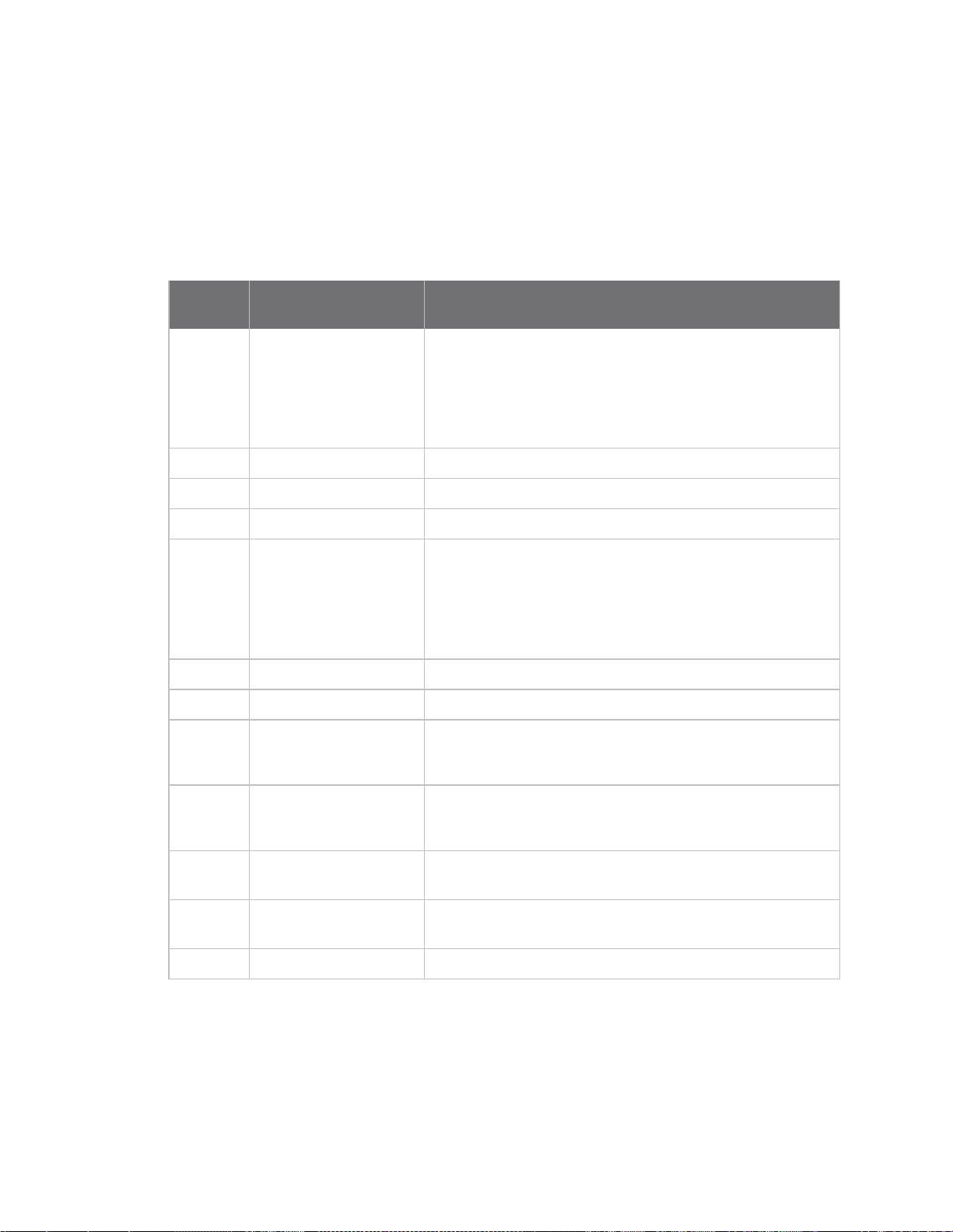
Data stream definitions Digital pulse counter (pcnt1) data stream definitions
Digital pulse counter (pcnt1) data stream definitions
The following table provides data stream definitions for the digital pulse counter (pcnt1) group for
Connect Sensor.
For additional information about data streams, refer to the following:
n Use data streams to analyze Connect Sensor data, see About data streams.
n Data streams group definitions, see Group definitions for Connect Sensor data streams.
Short
name Long name Description
aem Alarm enable mask
ahy Alarm hysteresis
alh Alarm high
all Alarm low
arm Alarm reason mask
cval Custom value Value calculated from the raw value (val).
dsc Description
ena Sensor enable
Alarms that are enabled during the report; the value in the
data stream equals the sum of the enabled alarms:
1 — Alarm high enabled (alh)
2 — Alarm low enabled (all)
For example, if you have the Alarm high and Alarm low
enabled, the aem data stream value is 3.
Hysteresis setting; for example, 2 (pulses).
High Threshold setting; for example, 4000 (pulses).
Low Threshold setting; for example 50 (pulses).
Alarms that are active during the report; the value in the
data stream equals the sum of the active alarms:
1 — Alarm high active (alh)
2 — Alarm low active (all)
For example, if the Alarm high and Alarm low are active
during the report, the arm data stream value is 3.
Identifies the user-configured description of the sensor.
Sensor enabled or disabled:
0 — Sensor off
1 — Sensor on
puen Pull-up enable
scl Custom value scaling
factor
unit Custom unit string Identifies the user-configured unit for the custom value
val Raw value Number of pulses since the last reading.
Pull-up resistor to 3.3 volts enabled or disabled:
0 — Pull-up disabled
1 — Pull-up enabled
Scaling factor used to calculate the custom value (cval) from
the raw value (val).
(cval).
Temperature sensor (temp1) data stream definitions
The following table provides data stream definitions for the temperature sensor (temp1) group for
Connect Sensor.
Digi Connect® Sensor User Guide
95
Page 96

Data stream definitions Modbus (modb1) data stream definitions
CAUTION! If Connect Sensor sends reports less than 15 minutes apart, it may result in
an internal temperature that is above the ambient temperature.
For additional information about data streams, refer to the following:
n Use data streams to analyze Connect Sensor data, see About data streams.
n Data streams group definitions, see Group definitions for Connect Sensor data streams.
Short
name Long name Description
aem Alarm enable mask
ahy Alarm hysteresis
alh Alarm high
all Alarm low
arm Alarm reason mask
ena Sensor enable
val Raw value Measured temperature.
Alarms that are enabled during the report; the value in the
data stream equals the sum of the enabled alarms:
1 — Alarm high enabled (alh)
2 — Alarm low enabled (all)
For example, if you have the Alarm high and Alarm low
enabled, the aem data stream value is 3.
Hysteresis setting; for example, 2.0 (Celsius).
High Threshold setting; for example, 50.0 (Celsius).
Low Threshold setting; for example -30.0 (Celsius).
Alarms that are active during the report; the value in the
data stream equals the sum of the active alarms:
1 — Alarm high active (alh)
2 — Alarm low active (all)
For example, if the Alarm high and Alarm low are active
during the report, the arm data stream value is 3.
Sensor enabled or disabled:
0 — Sensor off
1 — Sensor on
Modbus (modb1) data stream definitions
The following table provides data stream definitions for the Modbus protocol.
Note The Modbus protocol is available only with Connect Sensor+ hardware.
Some data stream information pushed to Remote Manager includes the Modbus device address
identified during device detection. For examples, see About data streams.
Digi Connect® Sensor User Guide
96
Page 97

Data stream definitions Modbus (modb1) data stream definitions
Short
name Long name Description
aem Alarm enable mask
baud Baud rate
dbt Data bits
ena Modbus protocol enable
err Error response status
value
mode Modbus serial
transmission mode
Modbus alarm enabled or disabled:
0 — Modbus alarm disabled
1 — Modbusalarm enabled
The baud rate. Value can be 600 - 230400.
The number of data bits that can be sent in a packet:
n 7
n 8
Modbus protocol enabled or disabled:
0 — Modbus protocol disabled
1 — Modbus protocol enabled
Error values:
1 - Illegal function
2 - Illegal data address
3 - Illegal data value
4 - Device failure
128 - Timeout
Specifies the Modbus serial transmission mode:
n rtu
n ascii
par Parity
saddr<1-4>Modbus station
addresses
sbt Stop bit
val Variable that returns a
value
vars<1-4> Corresponding Modbus
variable list
The check bit for detecting an error in transmission:
n none
n odd
n even
The station address number that is configured for the
Modbus sensor device.
The bit that marks the end of a unit transition.
n 1
n 2
Coils and discrete inputs will be 0 or 1.
Input and holding registers will be 16-bit unsigned integer
values, or signed floating point values, depending on
configuration.
Comma-separated list of variable addresses.
Digi Connect® Sensor User Guide
97
Page 98

Data stream definitions Modbus (modb1) data stream definitions
Data streams for Modbus protocol
Item Name Description
Connect Sensor
1
device ID Identifies the device.
2 Group
3 Modbus station address Identifies the station address that is being monitored.
4 Modbus variable address Identifies the variable address that is being monitored at the
5 Short name
Identifies the device-specific function or sensor for the data
stream. For example, modb1 corresponds to the sensor for a
device with Modbusprotocol enabled.
specified station address.
Identifies the specific data point. In this example, val is the
value that is returned.
Digi Connect® Sensor User Guide
98
Page 99

Use the CLI with Connect Sensor
If you have physical access to Connect Sensor, you can use the CLI (Command Line Interface) to
perform firmware updates, configure the device, and verify Connect Sensor status information.
To use CLI commands, you must connect a USB cable from a computer to Connect Sensor, and then
open a terminal program in the computer. You can enter CLI commands in the terminal program:
n Use the fwupdate command to update the firmware on the device.
n Use the status command to display device information.
n Use the set command combined with additional commands to configure device and sensor
settings.
The sections below explain how to connect to Connect Sensor and perform some standard functions.
n Open a terminal program and use CLIcommands
n Update the firmware using the CLI
n Use the CLIto view status information for the device
n Verify cellular network coverage using the CLI
n View battery life using the CLI
Open a terminal program and use CLIcommands
You can use CLI commands to perform actions on Connect Sensor. To use CLI commands, you must
connect a USB cable from a computer to Connect Sensor, and then open a terminal program in the
computer.
1. Open the Connect Sensor enclosure and make sure the battery is connected.
2. Connect a USB type A to B cable from your computer to the USB type B port.
Note Do not use the mini USB port, which is covered by a red X in the graphic below.
Digi Connect® Sensor User Guide
99
Page 100

Use the CLI with Connect Sensor Open a terminal program and use CLIcommands
3. You may need to install device drivers or wait for your computer to automatically install them
when connecting Connect Sensor to a computer using a USB cable. Digi recommends drivers
available at www.ftdichip.com/Drivers/VCP.htm.
4. Open a terminal program on a computer and connect to Connect Sensor using the following
configuration:
n Connection port: Connect to the COM port associated with the USB cable connected to
Connect Sensor
n Baud rate or bits per second: 115200
n Data: 8 bit
n Parity: None
n Stop: 1 bit
n Flow control: None
5. Press the Wake button on Connect Sensor and wait 5-10 seconds after the cellular LED starts
blinking.
6. Type your CLI command and press Enter.
n fwupdate: Update the firmware on the device. See Update the firmware using the CLI.
n status: Display status information. See Use the CLIto view status information for the
device.
n set: Configure device and sensor settings.
Digi Connect® Sensor User Guide
100
 Loading...