

Page 1

ConnectCore® 8X
SBC Pro
Hardware Reference Manual -- Preliminary
Page 2

Revision history—90002297
Revision Date Description
1P December 2018 Initial release
Trademarks and copyright
Digi, Digi International, and the Digi logo are trademarks or registered trademarks in the United
States and other countries worldwide. All other trademarks mentioned in this document are the
property of their respective owners.
© 2019 Digi International Inc. All rights reserved.
Disclaimers
Information in this document is subject to change without notice and does not represent a
commitment on the part of Digi International. Digi provides this document “as is,” without warranty of
any kind, expressed or implied, including, but not limited to, the implied warranties of fitness or
merchantability for a particular purpose. Digi may make improvements and/or changes in this manual
or in the product(s) and/or the program(s) described in this manual at any time.
Warranty
To view product warranty information, go to the following website:
www.digi.com/howtobuy/terms
Customer support
Gather support information: Before contacting Digi technical support for help, gather the following
information:
Product name and model
Product serial number (s)
Firmware version
Operating system/browser (if applicable)
Logs (from time of reported issue)
Trace (if possible)
Description of issue
Steps to reproduce
Contact Digi technical support: Digi offers multiple technical support plans and service packages.
Contact us at +1 952.912.3444 or visit us at www.digi.com/support.
Feedback
To provide feedback on this document, email your comments to
techcomm@digi.com
ConnectCore 8X SBC Pro Hardware Reference Manual -- Preliminary
2
Page 3

Include the document title and part number (ConnectCore 8X SBC Pro Hardware Reference Manual -Preliminary, 90002297 1P) in the subject line of your email.
ConnectCore 8X SBC Pro Hardware Reference Manual -- Preliminary
3
Page 4

Contents
About the ConnectCore 8X SBC Pro
Overview 5
Features and functionality 5
Block diagram 7
Connectors, jumpers, and switches 8
Top view 8
Bottom view 9
Description 9
ConnectCore 6UL SBC Pro interfaces
Power interfaces 12
DC-in jack connector 12
Additional power connector 12
Coin cell connector 12
5V supply connector 12
3.3V supply connector 13
Power and reset buttons 13
Boot mode 13
Debug interfaces 14
JTAG 14
SWD 14
Console port 14
Communication interfaces 15
10/100/1000 Mbps Ethernet 15
USB Host 15
USB 3.0 16
PCI Express 16
XBee 18
Multimedia interfaces 19
LVDS/MIPI-DSI display 19
MIPI camera 21
Parallel camera 21
Audio 22
Storage interfaces 22
MicroSD 22
Expansion and user interfaces 23
Expansion connector 23
User LEDs 25
ConnectCore 8X SBC Pro Hardware Reference Manual -- Preliminary
4
Page 5

About the ConnectCore 8X SBC Pro
Overview
The ConnectCore 8X SBC Pro is an ultra compact Pico-ITX board featuring the Digi ConnectCore 8X
System-on-Module that integrates an NXP i.MX8X application processor, LPDDR4 memory, eMMC flash
memory, WLAN/Bluetooth, power management IC for optimized power consumption applications and
a microcontroller assistant (MCA) for supporting additional functionality. This standalone product
serves as the reference design for the ConnectCore 8X System-on-Module and can also be used on its
own to accelerate time to market.
Features and functionality
n ConnectCore 8X System-on-Module:
l MX8X Dual/Quad ARM Cortex-A35 and single Cortex-M4F cores
l 2 GB, 32-bit LPDDR4-1200 memory
l 8 GB, 8-bit eMMC memory
l IEEE802.11 a/b/g/n/ac and Bluetooth 4.2
n Power:
l Power jack and industrial dedicated 5V power connector
l Coin-cell battery charger, supplying the on-module RTC
l Power and reset buttons
n Boot source configuration: internal eMMC, microSD, USB
n Debug:
l Standard IEEE 1149.1-2001 JTAG interface
l Single Wired Debug (SWD) interface for the microcontroller assistant
l TTL serial console
n Communication:
l Two 10/100/1000 Mbps Ethernet interfaces
l Two USB Host 2.0 interfaces on stacked USB A-type connector
l USB3.0 on USB C-type connector
l USB 2.0 OTG on micro AB-type connector
l PCI Express Mini Card slot supporting full-size cards
l XBee socket
l MIMO IEEE 802.11 a/b/g/n/ac + Bluetooth 4.2 dual mode
ConnectCore 8X SBC Pro Hardware Reference Manual -- Preliminary
5
Page 6

About the ConnectCore 8X SBC Pro Features and functionality
n Multimedia:
l Two LVDS interfaces, each one supporting up to four differential data pairs
l One MIPI CSI-2 camera
l One 8-bit parallel camera interface
l Audio CODEC supporting stereo headphone jack, speakers, mic-in, line-out and two line-in
lines
n Storage:
l microSD card slot
n Expansion/User interfaces
l Two 40-pin expansion connectors providing access to many different interfaces
l Two user LEDs
Note Some of the functionality mentioned above is specific to a ConnectCore 8X SBC Pro variant.
ConnectCore 8X SBC Pro Hardware Reference Manual -- Preliminary
6
Page 7
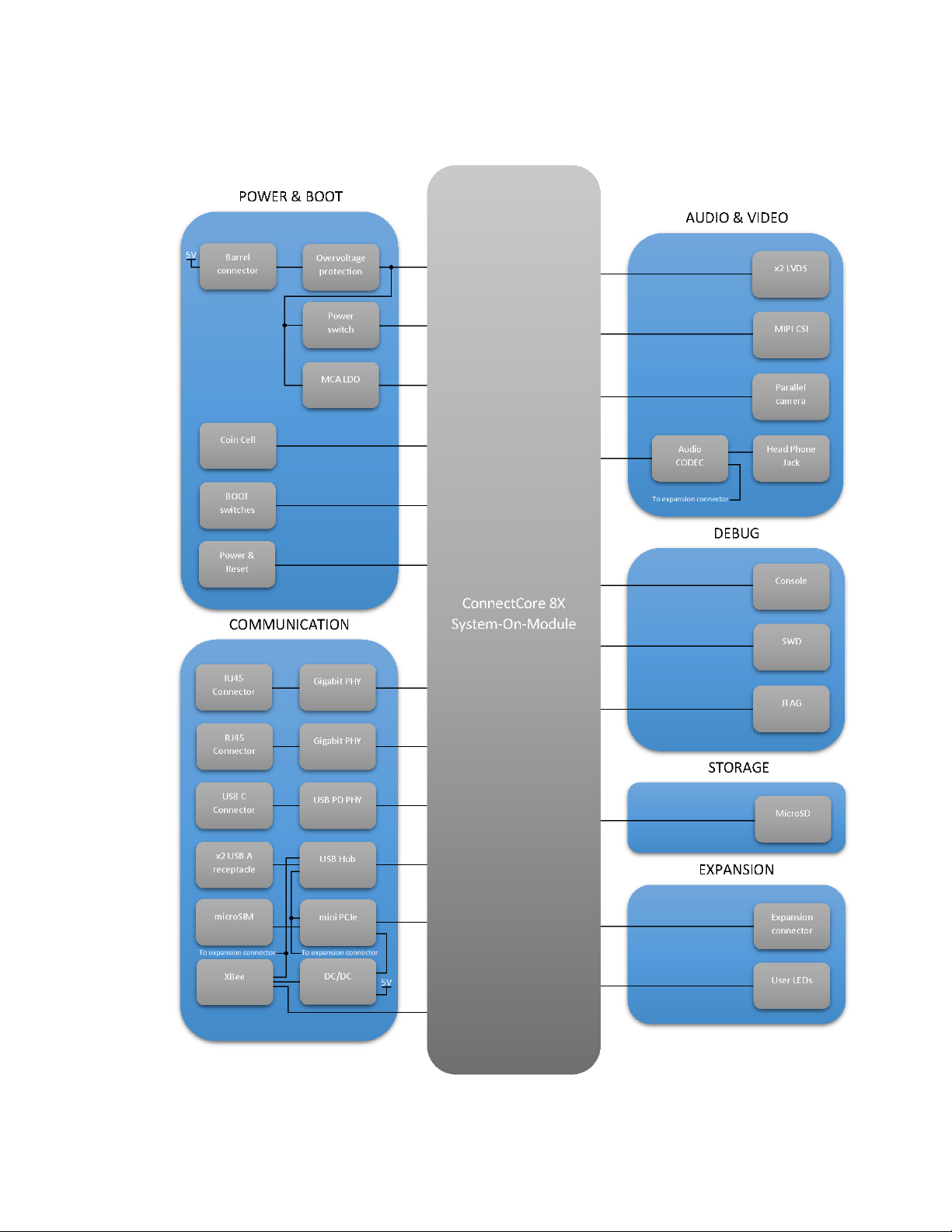
About the ConnectCore 8X SBC Pro Block diagram
Block diagram
ConnectCore 8X SBC Pro Hardware Reference Manual -- Preliminary
7
Page 8
About the ConnectCore 8X SBC Pro Connectors, jumpers, and switches
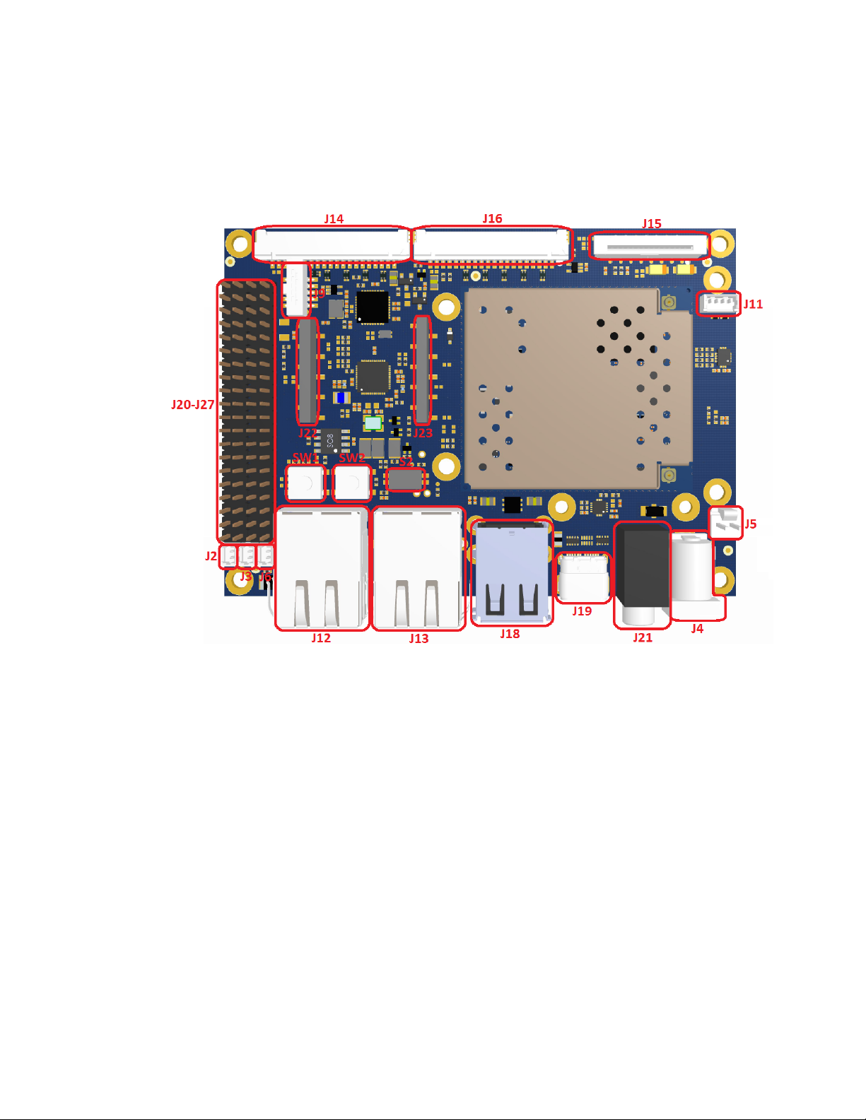
Connectors, jumpers, and switches
Top view
ConnectCore 8X SBC Pro Hardware Reference Manual -- Preliminary
8
Page 9

About the ConnectCore 8X SBC Pro Connectors, jumpers, and switches
Bottom view
Description
Connector Interface Manufacturer Manufacturer part number
J2 3.3V output Molex 53047-0210
J3 5V output Molex 53047-0210
J4 5V power-in jack Bobbintron CSCD443CCS011B00G
J5 5V power in TE Connectivity 640456-2
J6 Coin cell Molex 53047-0210
J7 Mini PCIe Foxconn AS0B226-S68Q-7H
J8 Micro SIM Molex 78727-0001
J9 SWD Samtec FTSH-105-01-F-DV
J10 MicroSD Molex 500873-0806
ConnectCore 8X SBC Pro Hardware Reference Manual -- Preliminary
9
Page 10

About the ConnectCore 8X SBC Pro Connectors, jumpers, and switches
Connector Interface Manufacturer Manufacturer part number
J11 Console Molex 53047-0410
J12 Ethernet 1 XMultiple XMG-J1B2211NPA-1-DIG
J13 Ethernet 2 XMultiple XMG-J1B2211NPA-1-DIG
J14 LVDS 0 Hirose DF14A-20P-1.25H
J15 MIPI camera FCI SFW15S-2STE1LF
J16 LVDS 1 Hirose DF14A-20P-1.25H
J17 Parallel camera Omron XF2M-2015-1A
J18 Stacked USB A-type connector KYCON KUSBX-AS2N
J19 USB C-type connector Molex 201267-0005
J20-J27 Expansion connectors Wurth Electronics Inc 61304021121
J22-J23 XBee socket Samtec SMM-110-02-F-S-P-TR
J28 USB micro AB-type connector KYCON KMMX-ABSMT5SG-30TR
CAD1 i.MX8X JTAG Tag Connect - -
CAD2 MCA SWD Tag Connect - -
SW1 Power button ITT KSC221JLFS
SW2 Reset button ITT KSC221JLFS
S2 Boot switches TDA02H0SB1 C&K Components
ConnectCore 8X SBC Pro Hardware Reference Manual -- Preliminary
10
Page 11

ConnectCore 6UL SBC Pro interfaces
Power interfaces 12
Boot mode 13
Debug interfaces 14
Communication interfaces 15
Multimedia interfaces 19
Storage interfaces 22
Expansion and user interfaces 23
ConnectCore 8X SBC Pro Hardware Reference Manual -- Preliminary
11
Page 12

ConnectCore 6UL SBC Pro interfaces Power interfaces
Power interfaces
DC-in jack connector
A 5V DC-in power jack connector (J4) provides power to the entire ConnectCore 8X SBC Pro system.
An overvoltage circuit protects the SBC from voltages higher than 6.5V (up to 12V). Behind the
overvoltage protection, a 5V load switch (U2) controls the power delivered to the SBC. The enable pin
of the power switch is controlled through 5V_SBC_PWR_ON signal from the CPU (GPIO0_13).
Additional power connector
In addition to the power jack assembled on the SBC Pro, a 2-pin, 2.54 mm pitch, latched vertical
connector on the top side of the board offers an alternative power rail to the whole system. This
power input is also protected against overvoltage events.
The following table shows the pinout of the power connector (J5):
Pin Signal name Description
1 VIN 5 power supply line.
2 GND
Coin cell connector
A 2-pin, 1.25 mm pitch straight connector (J6), provides battery charging functionality and power the
real-time-clock (RTC) interface when the main supply of the board is off. The main power supply rail
powers the RTC while it is connected. You can supply the RTC with a primary Lithium cell (nonrechargeable), a secondary Lithium cell (rechargeable) or a supercap.
The following table shows the pinout of the coin cell connector:
Pin Signal name Description
1 VCC_LICELL Power supply line for RTC.
2 GND
5V supply connector
The ConnectCore 8X SBC Pro provides a 2-pin, 1.25 mm pitch straight connector with a regulated 5V
supply for powering external circuitry. The 5V supply is generated on the on-board 5V regulator, which
is also used internally in the ConnectCore 8X SBC for powering the video interfaces. The following
table shows the pinout of the 5V supply connector (J3):
Pin Signal name Description
1 5V 5V power supply line.
2 GND
ConnectCore 8X SBC Pro Hardware Reference Manual -- Preliminary
12
Page 13

ConnectCore 6UL SBC Pro interfaces Boot mode
3.3V supply connector
Together with the 5V supply connector, another 2-pin, 1.25 mm pitch straight connector is supported
on the ConnectCore 8X SBC Pro providing a regulated 3.3V supply for powering external circuitry. The
3.3V power supply is generated on a buck regulator of the ConnectCore 8X PMIC (3V3_EXT power rail),
which is also used on-board for powering many interfaces of the ConnectCore 8X SBC Pro carrier
board. The following table shows the pinout of the 3.3V supply connector (J2):
Pin Signal name Description
1 3V3_EXT 3.3V power supply line.
2 GND
Power and reset buttons
TheON/OFFbutton (SW1) on the ConnectCore 8X SBC Pro is connected to the on-module MCA, and
provides the following functionality:
Board status Power button action Response
OFF Short press Power on
ON or SLEEP Long press for 5 seconds Power off
SLEEP Short press Wake up
ON Short press Sleep
TheRESETbutton (SW2) is also connected to the MCA, and by pressing it, the system will be reset.
Note The duration of some power button actions can be configured by the user. See the ConnectCore
8X online documentation for more information.
Boot mode
By default, the ConnectCore 8X module boots from the internal board settings, allowing it to boot
from the internal eMMC flash memory. For advanced functionality, the ConnectCore 8X SBC Pro
provides two switches (S2) to configure the SOM boot mode, as explained below:
SW2 SW1 Boot mode
Open Open eMMC
Open Close Fuses
Close Open microSD
Close Close Serial downloader
Serial downloader mode allows you to boot from USB. This booting process is ideal for recovery
purposes, such as if the boot loader is erased or cannot boot. If the system is configured to boot from
any other source (internal eMMC, microSD) but the booting process fails (e.g. wrong images loaded)
ConnectCore 8X SBC Pro Hardware Reference Manual -- Preliminary
13
Page 14

ConnectCore 6UL SBC Pro interfaces Debug interfaces
the system will also fall back to booting into USB debug mode, regardless the state of the switches.
For more information about the boot mode configuration, see the ConnectCore 8X System-on-Module
Hardware Reference Manual.
Debug interfaces
JTAG
The ConnectCore 8X SBC Pro provides a Tag Connect footprint for accessing the i.MX8X JTAG debug
port. This footprint is located on the bottom side of the board.
SWD
The ConnectCore 8X SBC Pro provides two options for programming and debugging the
Microcontroller Assist carried by the ConnectCore 8X SOM:
The first option is a 2x5, 1.27 mm pitch pin header (J9) on the top side of the board that, by default, is
not populated. The following table shows the pinout of the SWD connector:
Pin Schematic signal name Description
1 VCC_MCA MCA power supply line.
2 SWD_DIO/PWR_IO SWD bidirectional data line.
3 GND
4 SWD_CLK/PWR_IO SWD clock signal.
5 GND
6 NC
7 NC
8 NC
9 GND
10 SYS_RESET Reset signal for the MCA.
The second option is the ARM 10-pin standard-compliant Tag Connect footprint on the bottom side of
the board.
Console port
As the debug console port, the ConnectCore 8X SBC Pro provides a 4-pin, 1.25 mm pitch connector
(J11). The UART2 port of the ConnectCore 8X module is used for this purpose. The console signals is a
serial TTL, which travels through the console connector directly to the i.MX8X processor. A TTL-to-USB
cable can be used for accessing this console port from a host PC USB port. The following table shows
the pinout of this console connector:
ConnectCore 8X SBC Pro Hardware Reference Manual -- Preliminary
14
Page 15

ConnectCore 6UL SBC Pro interfaces Communication interfaces
Pin Signal name Description
1 CONSOLE_TX Transmission line.
2 CONSOLE_RX Receiver line.
3 3V3_EXT 3.3V power supply line.
4 GND
The default console setting are as follows:
Baud rate 115200
Data 8 bit
Parity none
Stop 1 bit
Flow control none
Communication interfaces
10/100/1000 Mbps Ethernet
The ConnectCore 8X SBC Pro provides two 10Base-T/100Base-Tx/1000Base-T Ethernet interfaces, by
using two Qualcomm Atheros AR8031 10/100/1000 Ethernet PHYs. These Ethernet PHYs are
connected to the i.MX8X ENET0 and ENET1 interfaces, respectively. Both Ethernet interfaces area
accessible through RJ-45 connectors (J12 and J13) with integrated link/activity LEDs, as specified in
the following table:
Green LED Yellow LED Link/activity status
ON OFF 10M Link
BLINK OFF 10M Active
ON OFF 100M Link
BLINK OFF 100M Active
ON ON 1000M Link
BLINK ON 1000M Active
For power management purposes, a dedicated power switch allows you to control the power over the
Ethernet PHYs.
USB Host
The ConnectCore 8X SBC Pro offers support for four USB Host interfaces through a USB Hub
controller:
ConnectCore 8X SBC Pro Hardware Reference Manual -- Preliminary
15
Page 16

ConnectCore 6UL SBC Pro interfaces Communication interfaces
l Two of them are available over a stackable dual USB A-type connector (J18) located on the front of
the board.
l One USB host is connected to thePCI Express Mini card connector.
l One USB host is connected to the XBee socket.
Both the PCI Express and the XBee USB buses can be disconnected from these interfaces and
accessed on the Expansion connector. These connections are managed through 0-ohm resistors:
USB_PCIe/EXPANSION_USB1 bus configuration
USB_PCIe connected EXPANSION_USB1 connected
R228/R229 Populated Not populated
R191/R192 Not populated Populated
XBEE/EXPANSION_USB2 bus configuration
XBEE connected EXPANSION_USB2
R76/R77 Populated Not populated
R78/R79 Not populated Populated
For power management purposes, a dedicated power switch allows you to control the power over the
USB Hub.
USB 3.0
One USB 3.0 bus is available through a USB C-type connector (J19) located on the top side of the
board. The USB 3.0 adds the SupesSpeed (SS) transfer rate, which works up to 5 Gb/s.
This interface can work at both USB 2.0 and USB 3.0 modes, and it can also work in both Host and
Device modes.
When the interface is configured to work in Host mode, the power delivered to the device can be
configured up to 3A.
Note In the first-availability kits of the ConnectCore 8X SBC Pro, the USB 3.0 bus is not supported on
the USB C-type connector. It will only work as USB 2.0.
PCI Express
The ConnectCore 8X SBC Pro provides a Mini PCI Express connector with the following interfaces:
l I2C.
l USB Host port (see USB Host section).
l PCIe interface, only available in carrier boards with non-wireless ConnectCore 8X SOM variants.
l One GPIO for the low-level PCIe wake-up signal.
l One GPIO for the low-level PCIe disable signal.
l One GPIO for the low level PCIe reset signal.
l SIM interface. The micro-SIM card slot is located on the bottom side of the board (J10).
ConnectCore 8X SBC Pro Hardware Reference Manual -- Preliminary
16
Page 17

ConnectCore 6UL SBC Pro interfaces Communication interfaces
For power management purposes, a dedicated 3.3V regulator allows you to control the power over
the PCIe interface.
The ConnectCore 8X SBC Pro has two 2.6 mm metalized drills supporting full-size PCI Express cards.
The following table shows the pinout of the PCIe connector:
Pin Signal name Description
1 PCIE_WAKE_N Wake-up signal.
2 PCIe_VCC 3.3V power supply line.
3 NC Not connected.
4 GND
5 NC Not connected.
6 VLDO4_1V5 1.5V power supply line.
7 NC Not connected.
8 PCIE_UIM_PWR Power supply for SIM card.
9 GND
10 PCIE_UIM_DATA SIM card data line.
11 PCIE_CLK_N PCIe clock pair line (-).
12 PCIE_UIM_CLK SIM card clock line.
13 PCIE_CLK_P PCIe clock pair line (+).
14 PCIE_UIM_RST SIM card reset line.
15 GND
16 PCIE_UIM_VPP Power supply for SIM programming.
17 NC Not connected.
18 GND
19 NC Not connected.
20 PCIE_DIS_N Disable signal.
21 GND
22 PCIE_RESET_N Reset signal.
23 PCIE_RX_N PCIe reception pair line (-).
24 PCIe_VCC 3.3V power supply line.
25 PCIE_RX_P PCIe reception pair line (+).
26 GND
27 GND
ConnectCore 8X SBC Pro Hardware Reference Manual -- Preliminary
17
Page 18

ConnectCore 6UL SBC Pro interfaces Communication interfaces
Pin Signal name Description
28 VLDO4_1V5 1.5V power supply line.
29 GND
30 PCIE_I2C_SCL I2C clock line.
31 PCIE_TX_N PCIe transmission pair line (-).
32 PCIE_I2C_SDA I2C data line.
33 PCIE_TX_P PCIe transmission pair line (+).
34 GND
35 GND
36 USB_PCIe_D_N USB differential data line (-).
37 GND
38 USB_PCIe_D_P USB differential data line (+).
39 PCIe_VCC 3.3V power supply line.
40 GND
41 PCIe_VCC
42 NC Not connected.
43 GND
44 NC Not connected.
45 NC Not connected.
46 NC Not connected.
47 NC Not connected.
48 VLDO4_1V5 1.5V power supply line.
49 NC Not connected.
50 GND
51 NC Not connected.
52 PCIe_VCC 3.3V power supply line.
XBee
The ConnectCore 8X SBC Pro provides an XBee socket supporting the connection of Digi XBee/XBeePRO modules. The XBee socket consist of two 10-pin, 2 mm pitch connectors (J22 and J23) which
follow the standard pinout of the XBee modules:
ConnectCore 8X SBC Pro Hardware Reference Manual -- Preliminary
18
Page 19

ConnectCore 6UL SBC Pro interfaces Multimedia interfaces
Description
3.3V power
supply line.
XBee UART
output data line.
XBee UART input
data line.
XBee reset line,
connected to
MCA_IO15.
Signal
name
XBEE_
VCC
MCA_
UART2_
RX
MCA_
UART2_
TX
- 4 4 - D08 AD3/DIO3 -174 -
XBEE_
RESET_
N
- 6 6 -
XBEE_
D_P
XBEE_
D_N
J12
pin XBee standard pin
1 1 - VCC ADC0/DIO0
- 20
2 2 - DOUT AD1/DIO1 -192 -
3 3 -
DIN/CONFIG_
N
5 5 - RESET_N RTS_
PWM0/RSSI
7 7 - Reserved VREF - 14 7 -
8 8 - Reserved ON/SLEEP_
AD2/DIO2 -183 -
N/DIO6 16
AD5/DIO5 -156 -
N - 13
J13
pin
1 -
5 MCA_
8 XBEE_
Signal
name Description
XBee UART
UART2_
RTS
ON/SLEEP_
N
clear to send
line.
XBee status
line, connected
to MCA_IO16.
XBee request
line, connected to
MCA_IO11.
The XBee can communicate with the ConnectCore 8X SOM in two different ways:
l Using the UART2 bus of the ConnectCore 8X on-module MCA.
l Using the USB bus.
Note The USB bus connected to the XBee socket is also connected to the expansion header. See USB
Host for detailed information.
XBEE_
SLEEP_
RQ
GND 10 10 - GND AD4/DIO4 -1110 -
9 9 - DTR_
N/SLEEP_
RQ/DI8
Multimedia interfaces
LVDS/MIPI-DSI display
The two MIPI-DSI/LVDS combo PHYs supported by the ConnectCore 8X module are available over two
different LVDS display connectors(J14 and J16) on the top side of the ConnectCore SBC Pro board:
CTS_
N/DIO7 12
9 MCA_
UART2_
CTS
XBee UART
request to send
lind.
ConnectCore 8X SBC Pro Hardware Reference Manual -- Preliminary
19
Page 20

ConnectCore 6UL SBC Pro interfaces Multimedia interfaces
l MIPI_DSI0 bus is connected to J14.
l MIPI_DSI1 bus is connected to J16.
These are 20-pin, 1.25 mm pitch connectors, whichprovides access to the following LVDS capabilities:
l Up to four LVDS differential data pairs.
l One LVDS differential clock pair.
l Interrupt signal with 10K pull-up resistor for touch screen.
l Control of the backlight contrast.
l I2C, shared with the MIPI-DSI connector.
l 3.3V power supply.
l 5V power supply.
Both the LVDS connectors exhibit the same pinout:
Pin Signal name Description
1 3V3_EXT 3.3V power supply line.
2 MIPI_DSI0/1_DATA0_N Transmission pair 0 data line (-).
3 MIPI_DSI0/1_DATA0_P Transmission pair 0 data line (+).
4 GND
5 MIPI_DSI0/1_DATA1_N Transmission pair 1 data line (-).
6 MIPI_DSI0/1_DATA1_P Transmission pair 1 data line (+).
7 GND
8 MIPI_DSI0/1_DATA2_N Transmission pair 2 data line (-).
9 MIPI_DSI0/1_DATA2_P Transmission pair 2 data line (+).
10 GND
11 MIPI_DSI0/1_CLK_N Transmission pair clock line (-).
12 MIPI_DSI0/1_CLK_P Transmission pair clock line (+).
13 GND
14 MIPI_DSI0/1_DATA3_N Transmission pair 3 data line (-).
15 MIPI_DSI0/1_DATA3_P Transmission pair 3 data line (+).
16 MIPI_DSI0/1_PWM0_OUT Backlight PWM.
17 MIPI_DSI0/1_I2C0_SCL I2C bus clock line.
18 MIPI_DSI0/1_I2C0_SDA I2C bus data line.
19 MIPI_DSI0/1_IRQ_N Display interrupt line.
20 VIN 5V power supply line.
ConnectCore 8X SBC Pro Hardware Reference Manual -- Preliminary
20
Page 21

ConnectCore 6UL SBC Pro interfaces Multimedia interfaces
MIPI camera
The ConnectCore 8X SBC Pro provides one MIPI camera interface compliant with the MIPI CSI-2
specification. A MIPI D-PHY is supported by the i.MX8X CPU, allowing direct connections between the
module and a MIPI CSI-2 compliant camera sensor.
This MIPI interface is available over a 15-pin, 1mm pitch, FCC connector on the top side of the board
(J15), whose pinout is described in the following table:
Pin Signal name Description
1 3V3_EXT 3.3V power supply line.
2 MIPI_CSI0_I2C0_SDA I2C bus data line.
3 MIPI_CSI0_I2C0_SCL I2C bus clock line.
4 NC Not connected.
5 MIPI_CSI0_RESET_N Camera reset line.
6 GND
7 MIPI_CSI0_CLK_P Transmission pair clock line (+).
8 MIPI_CSI0_CLK_N Transmission pair clock line (-).
9 GND
10 MIPI_CSI0_DATA1_P Transmission pair 1 data line (+).
11 MIPI_CSI0_DATA1_N Transmission pair 1 data line (-).
12 GND
13 MIPI_CSI0_DATA0_P Transmission pair 0 data line (+).
14 MIPI_CSI0_DATA0_N Transmission pair 0 data line (-).
15 GND
Parallel camera
The ConnectCore 8X SBC Pro provides one parallel camera interface (CSI). It is composed of an 8-bit
data bus, a master clock from the i.MX8X CPU and three synchronization signals (PIXCLK, HSYNC and
VSYNC).
This interface is available over a 20-pin, 0.5 mm pitch FCC connector (J17) located in top side of the
board, which has the following pinout:
Pin Signal name Description
1 GND
2 CSI_D00 Camera data line 0.
3 CSI_D01 Camera data line 1.
ConnectCore 8X SBC Pro Hardware Reference Manual -- Preliminary
21
Page 22

ConnectCore 6UL SBC Pro interfaces Storage interfaces
Pin Signal name Description
4 CSI_D02 Camera data line 2.
5 CSI_D03 Camera data line 3.
6 CSI_D04 Camera data line 4.
7 CSI_D05 Camera data line 5.
8 CSI_D06 Camera data line 6.
9 CSI_D07 Camera data line 7.
10 GND
11 CSI_MCLK Camera master clock line.
12 CSI_PCLK Camera pixel clock line.
13 CSI_HSYNC Camera horizontal sync line.
14 CSI_VSYNC Camera vertical sync line.
15 CSI_EN Camera enable signal.
16 CSI_RESET Camera reset line.
17 GND
18 CSI_SCL I2C bus clock line.
19 CSI_SDA I2C bus data line.
20 3V3_EXT 3.3V power supply line.
Audio
Audio functionality on the ConnectCore 8X SBC Pro supports headphone, speakers, line-out, two linein and microphone signals. A Maxim MAX98089 audio codec manages the audio interface, which
communicates with the i.MX8X CPU through I2C.For power management purposes, a dedicated
power switch allows you to control the power over the audio codec.
The headphone audio output of the audio codec is connected to a stereo audio jack (J21) located on
the front edge of the SBC Pro. The remaining audio signals mentioned above are available over the
expansion connector. See Expansion connector for more information.
Storage interfaces
MicroSD
A microSD socket (J10) is located on the bottom side of the board. This interface is connected to the
USDHC1 controller of the i.MX8X CPU.
ConnectCore 8X SBC Pro Hardware Reference Manual -- Preliminary
22
Page 23

ConnectCore 6UL SBC Pro interfaces Expansion and user interfaces
Expansion and user interfaces
Expansion connector
Two 2-row, 40-pin, 2.54 mm pitch headers (J20 and J27) are supported by the ConnectCore 8X SBC
Pro board. This headers acts as an expansion connector, offering access to many different interfaces
of the CPU and the MCA.
The following table show the pinout of the expansion connectors:
Description Signal name Pin Signal name Description
J20
MCA power supply line. VCC_MCA 1 2 GND
MCA 32 kHz clock output. MCA_
CLKOUT32K
MCA GPIO. MCA_IO6 5 6 MCA_IO7 MCA GPIO.
MCA GPIO. MCA_IO8 7 8 MCA_IO9 MCA GPIO.
MCA GPIO. MCA_IO10 9 10 MCA_IO5 MCA GPIO.
MCA GPIO. MCA_IO14 11 12 MCA_VREF_
i.MX8X GPIO. GPIO4_20 13 14 GPIO4_21 i.MX8X GPIO.
3.3V power supply rail of the RF
section of the SOM.
Connected to on-module
wireless MAC and to MCA_IO12.
Connected to on-module
wireless MAC.
Connected to on-module
wireless MAC.
Connected to on-module
wireless MAC.
3V3_RF 15 16 MCA_IO17 MCA GPIO.
BT_WAKEUP_
HOST
PCM_CLK 19 20 PCM_IN Connected to on-module
PCM_OUT 21 22 PCM_SYNC Connected to on-module
GPS_COEX 23 24 LTE_PRI Connected to on-module
3 4 1V8_EXT 1.8V power supply line.
MCA voltage reference
OUT
17 18 BT_
WAKEUP_
SLAVE
output.
Connected to on-module
wireless MAC.
wireless MAC.
wireless MAC.
wireless MAC.
Connected to on-module
wireless MAC.
Audio codec line A1 input. LINE1_IN_R 27 28 MIC_N Negative differential
Audio codec line A2 input. LINE1_IN_L 29 30 MIC_P Positive differential
Audio codec line B1 input. LINE2_IN_R 31 32 SPKL_P Positive left-channel
ConnectCore 8X SBC Pro Hardware Reference Manual -- Preliminary
QOW 25 26 LTE_SYNC Connected to on-module
wireless MAC.
microphone input.
microphone input.
speaker output.
23
Page 24

ConnectCore 6UL SBC Pro interfaces Expansion and user interfaces
Description Signal name Pin Signal name Description
Audio codec line B2 input. LINE2_IN_L 33 34 SPKL_N Negative left-channel
speaker output.
Right output line. LINE_OUT_R 35 36 SPKR_P Positive right-channel
speaker output.
Left output line. LINE_OUT_L 37 38 SPKR_N Negative right-channel
speaker output.
Input reset line of the
ConnectCore 8X SOM.
J27
3.3V power supply line. 3V3_EXT 1 2 GND
i.MX8X SPI0 clock line. SPI0_SCK 3 4 SPI0_CS0 i.MX8X SPI0 chip select 0
i.MX8X SPI0 bus input data line. SPI0_SDI 5 6 SPI0_CS1 i.MX8X SPI0 bus chip
i.MX8X SPI0 bus output data line. SPI0_SDO 7 8 SPI0_IRQ_N i.MX8X SPI0 bus
CAN1 low line. CAN1_L 9 10 CAN2_L CAN2 low line.
CAN1 high line. CAN1_H 11 12 CAN2_H CAN2 high line.
i.MX8X I2C3 bus clock line. EXP_I2C_SCL 13 14 EXP_I2C_
i.MX8X I2C3 bus data line. EXP_I2C_SDA 15 16 EXP_I2C_
i.MX8X UART0 bus transmission
line.
SYS_RESET 39 40 POWER_
BUTTON
IRQ_N
GPIO
UART0_TX 17 18 UART0_RTS_Bi.MX8X UART0 bus
Power button of the
ConnectCore 8X SOM.
line.
select 1 line.
interrupt line.
i.MX8X I2C3 bus
interrupt line.
i.MX8X I2C3 bus
dedicated GPIO.
request to send line.
i.MX8X UART0 bus receiver line. UART0_RX 19 20 UART0_CTS_Bi.MX8X UART0 bus clear
i.MX8X M40 UART bus
transmission line.
i.MX8X M40 UART bus receiver
line.
i.MX8X ADC channel 0. ADC_IN0 25 26 ADC_IN4 i.MX8X ADC channel 4.
i.MX8X ADC channel 1. ADC_IN1 27 28 ADC_IN5 i.MX8X ADC channel 4.
Connected to SN65HVD233DR
Rs pin (8).
ConnectCore 8X SBC Pro Hardware Reference Manual -- Preliminary
M40_UART_TX21 22 RS485_A RS485 A line.
M40_UART_RX23 24 RS485_B RS485 B line.
CAN1_MODE 29 30 GPIO4_19 i.MX8X GPIO.
to send line.
24
Page 25

ConnectCore 6UL SBC Pro interfaces Expansion and user interfaces
Description Signal name Pin Signal name Description
Connected to SN65HVD233DR
Rs pin (8).
USB expansion bus 2 differential
data line (+).
USB expansion bus 2 differential
data line (-).
i.MX8X GPIO. GPIO5_09 37 38 VCC_LICELL Power supply line for
CAN2_MODE 31 32 EXPANSION_
USB1_D_P
EXPANSION_
USB2_D_P
EXPANSION_
USB2_D_N
GND 39 40 5V 5V power supply line.
33 34 EXPANSION_
USB1_D_N
35 36 GPIO0_12 i.MX8X GPIO.
USB expansion bus 1
differential data line (+).
USB expansion bus 1
differential data line (-).
RTC.
User LEDs
Two user LEDs are located on the top side of the ConnectCore 8X SBC Pro board. Both LEDs are
connected to GPIOs from the MCA as follows:
Device MCA port
User LED0 PTD5
User LED1 PTD6
ConnectCore 8X SBC Pro Hardware Reference Manual -- Preliminary
25
 Loading...