

Page 1

ConnectCore 8M Mini
Development Board
Hardware Reference Manual
Page 2

Revision history—90002455
Revision Date Description
A March 2020 Initial release.
Trademarks and copyright
Digi, Digi International, and the Digi logo are trademarks or registered trademarks in the United
States and other countries worldwide. All other trademarks mentioned in this document are the
property of their respective owners.
© 2021 Digi International Inc. All rights reserved.
Disclaimers
Information in this document is subject to change without notice and does not represent a
commitment on the part of Digi International. Digi provides this document “as is,” without warranty of
any kind, expressed or implied, including, but not limited to, the implied warranties of fitness or
merchantability for a particular purpose. Digi may make improvements and/or changes in this manual
or in the product(s) and/or the program(s) described in this manual at any time.
Warranty
To view product warranty information, go to the following website:
www.digi.com/howtobuy/terms
Customer support
Gather support information: Before contacting Digi technical support for help, gather the following
information:
Product name and model
Product serial number (s)
Firmware version
Operating system/browser (if applicable)
Logs (from time of reported issue)
Trace (if possible)
Description of issue
Steps to reproduce
Contact Digi technical support: Digi offers multiple technical support plans and service packages.
Contact us at +1 952.912.3444 or visit us at www.digi.com/support.
ConnectCore 8M Mini Development Board Reference Manual
2
Page 3

Feedback
To provide feedback on this document, email your comments to
Include the document title and part number (ConnectCore 8M Mini Development Board Reference
Manual, 90002455 A) in the subject line of your email.
techcomm@digi.com
ConnectCore 8M Mini Development Board Reference Manual
3
Page 4

Contents
About the ConnectCore 8M Mini development board
Features and functionality 5
Placement and connectors 7
Interfaces
Power 12
DC-in connectors 12
Power architecture configuration 12
Coin cell/Supercap 12
Battery connector 13
Power and reset buttons 13
System boot 13
Debug 14
JTAG 14
SWD 14
Console ports 15
USB recovery 15
Communication 16
Gigabit Ethernet 16
RS-485 16
CAN 17
USB Host 17
USB OTG 17
Mini PCIe 17
XBee 18
Multimedia 18
HDMI, LVDS, and MIPI displays 18
MIPI-CSI camera 19
Audio 20
Storage interfaces 21
MicroSD 21
User interfaces 21
User LED 21
User button 21
ConnectCore 8M Mini Development Board Reference Manual
4
Page 5

About the ConnectCore 8M Mini development board
The Digi ConnectCore 8M Mini Development Board is a system-on-module (SOM) development kit that
streamlines the prototyping of a wide range of industrial and medical applications.
Built on the i.MX 8M Mini processor with power-efficient quad ARM® Cortex®-A53 and Cortex-M4 cores,
Digi ConnectCore 8M Mini combines pre-certified wireless connectivity (802.11 a/b/g/n/ac and
Bluetooth® 5) with Digi TrustFence® and Digi Microcontroller Assist™.
Features and functionality
n Power:
l 5 V input power jack connector
l Battery connector
l Coin cell connector
l On-board supercap supporting RTC functionality
l Power and reset buttons
n Boot source configuration: eMMC, USB, microSD
n Debug:
l Standard IEEE 1149.1 JTAG interface
l Single Wired Debug (SWD) interface for the on-module Digi Microcontroller Assist™ (MCA)
l USB console
l USB for system-on-module recovery
n Multimedia:
l HDMI display*.
l LVDS display with backlight control and I2C touch interface*.
l MIPI-DSI*.
l MIPI-CSI camera supporting two data lanes. Two additional data lanes are available in the
expansion connector.
n Storage:
l MicroSD card slot
n Communication:
l Gigabit Ethernet 10/100/1000 with RJ-45 connector
l x2 USB host (dual type-A)
l USB OTG on micro AB-type connector
ConnectCore 8M Mini Development Board Reference Manual
5
Page 6

About the ConnectCore 8M Mini development board Features and functionality
l x5 GPIOs
l CAN FD (through SPI interface)
l RS-485
l PCI Express Mini Card slot supporting half- and full-size cards, with USB, PCIe and Micro-
SIM connection.
l Audio interfaces:
o
x1 3.5 mm headphone jack
o
x1 3.5 mm microphone jack
o
x2 speaker outputs
o
x1 line-out output
o
x2 line-in inputs
l x2 XBee sockets, one supporting XBee cellular
l x2 SMA antenna connectors, one for the on-module antenna and another for the Mini PCIe
card
n User interfaces:
l x2 user buttons
l x3 user LEDs
n Dimensions:
l 210 x 130 mm
Note * Only one display interface can be enabled at a time.
ConnectCore 8M Mini Development Board Reference Manual
6
Page 7
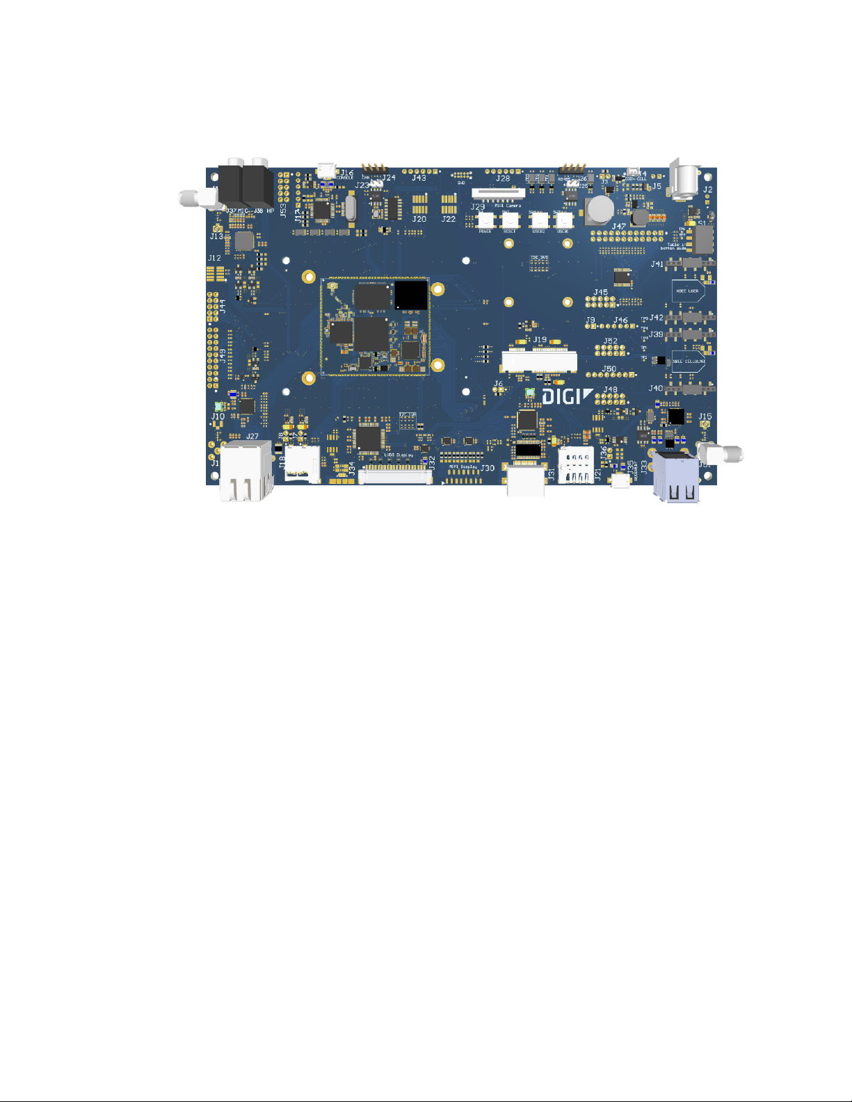
About the ConnectCore 8M Mini development board Placement and connectors
Placement and connectors
ConnectCore 8M Mini Development Board Reference Manual
7
Page 8

About the ConnectCore 8M Mini development board Placement and connectors
Connector Interface Manufacturer Manufacturer Part Number
J1 5 V power-in jack Bobbintron SCD443CCS011B00G
J2 Alternative 5 V power-in TE Connectivity 640456-2
J3 MCA power consumption - -
J4 Coin-cell Molex 53047-0210
J5 Battery connector TE Connectivity 640456-2
J6 SOM power consumption - -
J7 3V3 DVK power consumption - -
J8 1V8 DVK power consumption - -
J9 Debug - -
J10 u.FL antenna connector Hirose U.FL-R-SMT(10)
J11 SMA antenna connector Bobbintron SMA A700T
J12 Wireless MAC JTAG Samtec FTSH-105-01-F-DV
ConnectCore 8M Mini Development Board Reference Manual
8
Page 9

About the ConnectCore 8M Mini development board Placement and connectors
Connector Interface Manufacturer Manufacturer Part Number
J13 u.FL antenna connector Hirose U.FL-R-SMT(10)
J14 SMA antenna connector Bobbintron SMA A700T
J15 u.FL antenna connector Hirose U.FL-R-SMT(10)
J16 Console (USB) Kycon KMMX-ABSMT5SG-30TR
J17 Console (TTL) - -
J18 MicroSD Amphenol GTFP08431BEU
J19 Mini PCIe Foxconn AS0B226-S68N-7F
J20 i.MX8M JTAG Samtec FTSH-105-01-F-DV
J21 MicroSIM Molex 78727-0001
J22 MCA SWD Samtec FTSH-105-01-F-DV
J23 CAN termination resistor - -
J24 CAN Samtec TSW-104-14-G-S
J25 RS485 termination resistor - -
J26 RS485 Samtec TSW-104-14-G-S
J27 Ethernet Xmultiple XMG-J1B2211NPA-1-DIG
J28 MIPI camera extension - -
J29 MIPI camera Amphenol SFW15S-2STE1LF
J30 MIPI display Amphenol SFW15S-2STE1LF
J31 HDMI Adam Tech HDMI-S-RA-TSMT
J32 LVDS Hirose DF14A-20P-1.25H(25)
J33 USB Host Excel Cell Electronic ESB01211000Z
J34 USB OTG Kycon KMMX-ABSMT5SG-30TR
J35 USB recovery Kycon KMMX-ABSMT5SG-30TR
J36 Force USB recovery - -
J37 Microphone input CUI Devices SJ1-3533NG
J38 Headphones output CUI Devices SJ1-3533NG
J39-J40 XBee Cellular Samtec SMM-110-02-F-S-P-TR
J41-J42 XBee user Samtec SMM-110-02-F-S-P-TR
J43 Control signals - -
ConnectCore 8M Mini Development Board Reference Manual
9
Page 10

About the ConnectCore 8M Mini development board Placement and connectors
Connector Interface Manufacturer Manufacturer Part Number
J44 Wireless signals - -
J45 UARTs - -
J46 GPIOs - -
J47 SAI1 - -
J48 I2C - -
J49 Wireless signals - -
J50 Clocks - -
J51 SMA antenna connector Bobbintron SMA A700T
J52 Power rails - -
J53 Audio - -
J54 Supercap
ConnectCore 8M Mini Development Board Reference Manual
10
Page 11

Interfaces
The following interfaces are available on the ConnectCore 8M Mini:
Power 12
System boot 13
Debug 14
Communication 16
Multimedia 18
Storage interfaces 21
User interfaces 21
ConnectCore 8M Mini Development Board Reference Manual
11
Page 12

Interfaces Power
Power
DC-in connectors
The input voltage of the ConnectCore 8M Mini Development Board is 5 V. You can use one of two
connectors to power the entire system. Note that you can only enable one at a time.
n DC-in power jack connector
n J2, a 2-pin, 2.54 mm pitch connector:
Pin Signal name Description
1 VIN 5 V power supply rail
2 GND Ground
An overvoltage circuit protects the board from overvoltage and overcurrent events. Downstream from
these input power protections, there are three regulators/switches for powering both the SOM and
the carrier board circuitry:
n MCA LDO (U2): This regulator generates the 3.3 V that powers the on-module MCA.
n 5 V Load switch: A 5 V load switch controls the power delivery to some interfaces (CAN, HDMI,
LVDS).
n 3.3 V On-board regulator (U4): This buck regulator powers the XBee and PCIe sockets.
Power architecture configuration
SOM input supply Power rail connected to Nominal operating voltage
VSYS VIN (input supply of the board) 5V
VCC_MCA Dedicated 3.3V regulator 3V (considering forward diode)
VDD_USDHC2 MUX_3V3_1V8 3.3V
VDD_ENET 1V8 1.8V
VDD_UART 3V3 3.3V
Coin cell/Supercap
A 70 mF supercap supports RTC applications. Connector J4 on the board is included for attaching a
coin-cell:
Pin Signal name Description
1 VCC_RTC Power supply for RTC
2 GND Ground
ConnectCore 8M Mini Development Board Reference Manual
12
Page 13

Interfaces System boot
Note Coin-cell charger support will depend on the version of the SOM soldered to the Development
Board.
Battery connector
The development board includes one battery connector (J5):
Pin Signal name Description
1 VSYS2 Battery power supply
2 GND Ground
Power applied to this power supply feeds the part of the ConnectCore 8M Mini SOM that supports
battery applications.
Power and reset buttons
One power button (SW1) and one reset button (SW2) are included on the development board. These
buttons support the following functionality:
Button Board status Power button action Response
SW1 OFF Short press Power on
SW2 - Short press Reset
System boot
The ConnectCore 8M Mini supports different boot modes (see the ConnectCore 8M Mini Hardware
Reference Manual for detailed information). The development board supports these boot modes, but
some require changes to the populated components.
A quadruple switch (S1) allows you to easily swap between four different boot modes. Two of the four
switches are used for this purpose:
SW1.2 SW1.1 Description
Open Open Boot from eMMC0
Open Close Boot from fuses
ON or SLEEP Long press for 5 seconds Power off
SLEEP Short press Wake-up
ON Short press Sleep
Close Open Boot from microSD
Close Close Serial downloader
ConnectCore 8M Mini Development Board Reference Manual
13
Page 14

Interfaces Debug
Debug
JTAG
A JTAG connector (J20, not populated by default) is available on the development board for accessing
the JTAG interface of the CPU:
Pin Signal name Description
1 1V8_SOM_EXT 1.8 V power supply
2 JTAG_TMS Mode select line
3 GND Ground
4 JTAG_TCK Clock line
5 GND Ground
6 JTAG_TDO Data output line
7 NC Not connected
8 JTAG_TDI Data input line
9 GND Ground
10 POR_B Reset line
SWD
The development board provides two options for programming and debugging the ConnectCore 8M
Mini on-module MCA:
n J22, a 10 pin (2x5), 1.27 mm pitch connector:
Pin Signal name Description
1 VCC_MCA 3.3 V supply voltage of the MCA
2 SWD_DIO Data I/O line
3 GND Ground
4 SWD_CLK Clock line
5 GND Ground
6 NC Not connected
7 NC Not connected
8 NC Not connected
9 GND Ground
10 SYS_RESET Reset line
ConnectCore 8M Mini Development Board Reference Manual
14
Page 15

Interfaces Debug
n Tag Connect footprint.
Console ports
A dedicated USB micro AB-type port (J16) provides access to the two console ports of the
ConnectCore 8M Mini system-on-module:
n i.MX 8M Mini Cortex A-53 serial debug port
n i.MX 8M Mini Cortex-M4 serial debug port
The USB port is routed directly to the FTDI FT2232D bridge, which converts the USB bus into TTL
UARTs:
Debug port UART port
Cortex A-53 UART1
Cortex-M4 UART4
Note that UART4 is not connected to the FTDI chip by default. To access this UART, change the
following resistors:
n Depopulate R152 and R154
n Populate R152 and R152
You can also access the UART ports at TTL level through the J17 connector:
Pin Signal name Description
1 3V3_DBG 3.3 V power rail
2 CONSOLE_TX CPU console port transmission line
3 CONSOLE_RX CPU console port receiver line
4 UART_M7_TX M7 console port transmission line
5 UART_M7_RX M7 console port receiver line
6 GND Ground
Default console port settings
n Baud rate: 115200
n Data: 8 bit
n Parity: none
n Stop: 1 bit
n Flow control: none
USB recovery
The development board includes a dedicated USB micro AB-type port (J35) for recovery. This port
detects when a cable is plugged in and automatically switches the USB1 bus of the CPU from its
ConnectCore 8M Mini Development Board Reference Manual
15
Page 16

Interfaces Communication
default USB Host connection to the recovery port:
Note If J36 is closed, then the USB1 bus of the CPU is forced to be connected to the recovery
connector J35.
Communication
Gigabit Ethernet
One 10Base-T/100Bae-Tx/1000Base-T Ethernet interface is fully integrated in the board through the
AR8031 Ethernet PHY. The bus is accessible through a RJ-45 connector with integrated link/activity
LEDs, as specified in the following table:
Green LED Yellow LED Link/activity status
ON OFF 10M/100M Link
BLINK OFF 10M/100M Active
ON ON 1000M Link
BLINK ON 1000M Active
RS-485
The development board supports one RS-485 half-duplex bus, available on an expansion connector
(J26):
ConnectCore 8M Mini Development Board Reference Manual
16
Page 17

Interfaces Communication
Pin Signal name Description
1 3V3_SOM_EXT 3.3 V power supply
2 RS485_B RS485 B line
3 RS485_A RS485 A line
4 GND Ground
UART3 is used for this purpose, together with the LTC2862 transceiver. You can connect a 120Ω
terminator resistor to the bus by closing J25.
Note UART3 is also connected to expansion header J45. To use these lines on this connector, remove
resistors R291, R359, and R292 to avoid collision with the RS485 transceiver.
CAN
One CAN FD bus is available on the development board through connector J24:
Pin Signal name Description
1 5V 5 V power suppy
2 CAN1_H CAN high line
3 CAN1_L CAN low line
4 GND Ground
The i.MX 8M Mini CPU does not support any CAN interface, so the SPI3 bus of the CPU in combination
with the MCP2517FD controller and the TCAN1042 transceiver are used for this purpose.
A 120Ω terminator resistor can be connected to the bus by closing J23.
USB Host
Up to four USB Host interfaces are supported by the development board through the USB2514B USB
hub:
n Two of the ports are available over a stackable dual USB A-type connector.
n One port is connected to the Mini PCI Express slot.
n One port is connected to the XBee Cellular socket.
USB OTG
A micro-AB type receptacle for USB OTG connection is available on the CC8M Mini development board.
This interface can operate in both Host and Device mode.
Mini PCIe
The development board provides one Mini PCI Express socket (J19) supporting USB, PCIe and I2C
connection to the ConnectCore 8M Mini module. A micro SIM socket is also connected to the Mini PCI
Express slot.
ConnectCore 8M Mini Development Board Reference Manual
17
Page 18

Interfaces Multimedia
XBee
Two XBee sockets are populated on the development board. One of the sockets supports the XBee
Cellular.
Multimedia
HDMI, LVDS, and MIPI displays
The ConnectCore 8M Mini System-on-Module supports only one MIPI-DSI display interface. On the
ConnectCore 8M Mini Development Board, this MIPI-DSI display is managed so that three different
display interfaces are supported, although only one of them can work at a time.
n HDMI: The Lontium LT8912B bridge is populated on the development board to adapt the MIPI-
DSI interface to HDMI. This HDMI interface is available over a standard HDMI connector.
n LVDS: The SN65DSI83 bridge is also populated on the development board to adapt the MIPI-DSI
interface to LVDS. This LVDS is available over a 20-pin connector (J32), also supporting
backlight control and I2C touch controller:
Pin Signal name Description
1 3V3_SOM_EXT 3.3 V power supply
2 LVDS_TX0_N Data pair 0 (-) line
3 LVDS_TX0_P Data pair 0 (+) line
4 GND Ground
5 LVDS_TX1_N Data pair 1 (-) line
6 LVDS_TX1_P Data pair 1 (+) line
7 GND Ground
8 LVDS_TX2_N Data pair 2 (-) line
9 LVDS_TX2_P Data pair 2 (+) line
10 GND Ground
11 LVDS_CLK_N Clock pair (-) line
12 LVDS_CLK_P Clock pair (+) line
13 GND Ground
14 LVDS_TX3_N Data pair 3 (-) line
15 LVDS_TX3_P Data pair 3 (+) line
16 LVDS_PWM_OUT Backlight PWM (connected to MCA_IO17)
17 LVDS_I2C_SCL i.MX8M I2C2 bus clock line
ConnectCore 8M Mini Development Board Reference Manual
18
Page 19

Interfaces Multimedia
Pin Signal name Description
18 LVDS_I2C_SDA i.MX8M I2C2 bus data line
19 LVDS_IRQ_N Interrupt line (connected to i.MX8M GPIO4_18)
20 5V 5 V power supply
n MIPI-DSI: the native MIPI-DSI interface of the SOM is available over a 15-pin connector (J30):
Pin Signal name Description
1 MIPI_EXT_DATA0_P Data pair 0 (+) line
2 MIPI_EXT_DATA0_N Data pair 0 (-) line
3 GND Ground
4 MIPI_EXT_DATA1_P Data pair 1 (+) line
5 MIPI_EXT_DATA1_N Data pair 1 (-) line
6 GND Ground
7 MIPI_EXT_DATA2_P Data pair 2 (+) line
8 MIPI_EXT_DATA2_N Data pair 2 (-) line
9 GND Ground
10 MIPI_EXT_DATA3_P Data pair 3 (+) line
11 MIPI_EXT_DATA3_N Data pair 3 (-) line
12 GND Ground
13 MIPI_EXT_CLK_P Clock pair (+) line
14 MIPI_EXT_CLK_N Clock pair (-) line
15 GND Ground
MIPI-CSI camera
The development board provides a MIPI camera serial interface (MIPI-CSI) over a 15-pin connector
(J29):
Pin Signal name Description
1 3V3_SOM_EXT 3.3 V power supply
2 MIPI_CSI_I2C_SDA i.MX8M I2C2 bus data line
3 MIPI_CSI_I2C_SCL i.MX8M I2C2 bus clock line
4 NC Not connected
ConnectCore 8M Mini Development Board Reference Manual
19
Page 20

Interfaces Multimedia
Pin Signal name Description
5 MIPI_CSI_RESET_N Rreset line (connected to i.MX8M GPIO1_12)
6 GND Ground
7 MIPI_CSI_CLK_P Clock pair (+) line
8 MIPI_CSI_CLK_N Clock pair (-) line
9 GND Ground
10 MIPI_CSI_DATA1_P Data pair 1 (+) line
11 MIPI_CSI_DATA1_N Data pair 1 (-) line
12 GND Ground
13 MIPI_CSI_DATA0_P Data pair 0 (+) line
14 MIPI_CSI_DATA0_N Data pair 0 (-) line
15 GND Ground
By default, only two data lanes are supported. The additional two data lanes are available over an
expansion connector (J28):
Pin Signal name Description
1 MIPI_CSI_DATA3_P Data pair 3 (+) line
2 MIPI_CSI_DATA3_N Data pair 3 (-) line
3 GND Ground
4 MIPI_CSI_DATA2_P Data pair 2 (+) line
5 MIPI_CSI_DATA2_N Data pair 2 (-) line
6 GND Ground
Audio
The Maxim MAX98089 audio codec manages the audio interface on the development board. The board
provides the following audio functionality:
n 3.5 mm headphone jack
n 3.5 mm microphone jack
n x2 speaker outputs (left and right)
n x1 line-out output
n x2 line-in inputs
The speakers, line-out signals, and line-in signals are available over a 10-pin connector (J53):
ConnectCore 8M Mini Development Board Reference Manual
20
Page 21

Interfaces Storage interfaces
Pin Signal name Description
1 LINE1_IN_R Single-ended line input A1
2 LINE1_IN_L Single-ended line input A2
3 LINE2_IN_R Single-ended line input B1
4 LINE2_IN_L Single-ended line input B2
5 LINE_OUT_R Right line output
6 LINE_OUT_L Left line output
7 SPKL_P Positive left-channel class D speaker output
8 SPKL_N Negative left-channel class D speaker output
9 SPKR_P Positive right-channel class D speaker output
10 SPKR_N Negative right-channel class D speaker output
Storage interfaces
MicroSD
A microSD socket (J18) is located on the top side of the board, next to the RJ45 connector. This
interface is connected to the USDHC2 port of the i.MX8M Mini CPU.
User interfaces
User LED
Three LEDs are available on the development board: one green, one yellow, and one red. All of them
are connected to SOM GPIOs.
User button
Two buttons are available on the development board, both of them connected to the SOM.
ConnectCore 8M Mini Development Board Reference Manual
21
 Loading...