

Page 1

ConnectCore® for i.MX6 SBC
Hardware Reference Manual
Page 2
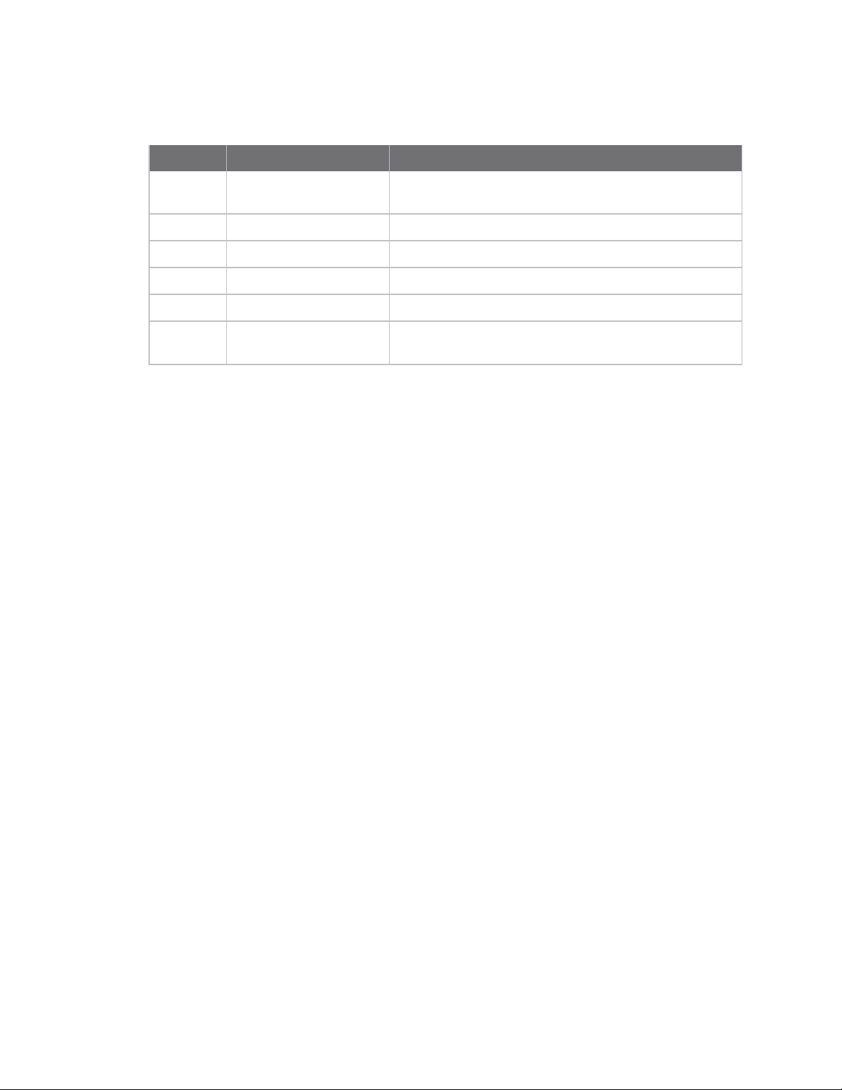
Revision history—90001499
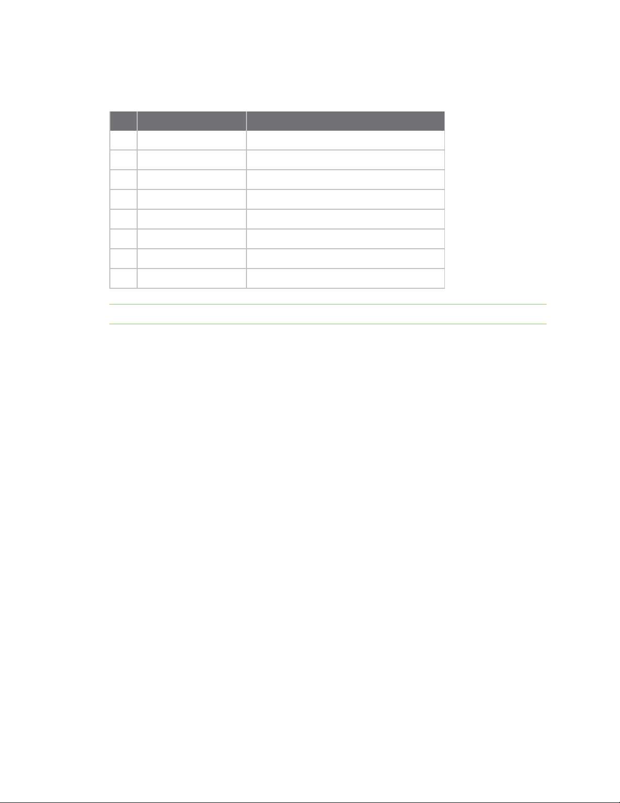
Revision Date Description
E June 2017 Modified regulatory and certification information as
F July 2017 Add RGB values to parallel display interface chart.
G April 2018 Update boot mode resistor configuration table.
H April 2019 Add Brazilian regulatory information.
J October 2019 Add XBee socket note.
K July 2020 Modify XBee socket connection details; add link to variants
Trademarks and copyright
Digi, Digi International, and the Digi logo are trademarks or registered trademarks in the United
States and other countries worldwide. All other trademarks mentioned in this document are the
property of their respective owners.
© 2020 Digi International Inc. All rights reserved.
required by RED (Radio Equipment Directive).
page.
Disclaimers
Information in this document is subject to change without notice and does not represent a
commitment on the part of Digi International. Digi provides this document “as is,” without warranty of
any kind, expressed or implied, including, but not limited to, the implied warranties of fitness or
merchantability for a particular purpose. Digi may make improvements and/or changes in this manual
or in the product(s) and/or the program(s) described in this manual at any time.
Warranty
To view product warranty information, go to the following website:
www.digi.com/howtobuy/terms
Customer support
Gather support information: Before contacting Digi technical support for help, gather the following
information:
Product name and model
Product serial number (s)
Firmware version
Operating system/browser (if applicable)
Logs (from time of reported issue)
Trace (if possible)
Description of issue
ConnectCore® for i.MX6 SBC Hardware Reference Manual
2
Page 3

Steps to reproduce
Contact Digi technical support: Digi offers multiple technical support plans and service packages.
Contact us at +1 952.912.3444 or visit us at www.digi.com/support.
Feedback
To provide feedback on this document, email your comments to
Include the document title and part number (ConnectCore® for i.MX6 SBC Hardware Reference
Manual, 90001499 K) in the subject line of your email.
techcomm@digi.com
ConnectCore® for i.MX6 SBC Hardware Reference Manual
3
Page 4

Contents
About this guide
Additional resources 6
ConnectCore 6 SBC overview
Introduction 8
Features and functionality 8
Placement - top side 10
Placement - bottom side 10
SBC block diagram 11
Variants 11
ConnectCore 6 SBC interfaces
DC-in connector 13
Power LED 13
Overvoltage protection 14
5V load switch 14
SBC coin cell connector 15
SBC boot configuration 16
SBC boot source switches 16
5V supply connector 17
3.3V supply connector 18
Boot mode 19
Power and reset functions 20
5V supply connector 20
3.3V supply connector 21
JTAG 21
SWD 23
SBC console port 24
SATA 26
microSD 27
Gigabit Ethernet 28
Gigabit Ethernet PHY address 29
USB OTG 31
USB host 32
PCI express mini card 34
SBC micro-SIM card slot 38
XBee 39
Parallel display 41
ConnectCore® for i.MX6 SBC Hardware Reference Manual
4
Page 5

LVDS 44
HDMI 47
MIPI display 49
MIPI camera 51
Parallel camera 53
Audio 56
CAN 58
CAN termination resistors 59
UART 60
I2C 62
SPI 64
GPIO and user LEDs 65
Specifications
Electrical specifications 69
Supply voltages 69
Mechanical specifications 70
Environmental specifications 71
WLAN specifications 71
Bluetooth specifications 71
Regulatory information
Maximum power and frequency specifications 73
Europe 73
Declarations of Conformity 73
CE mark 73
Brazil 74
ConnectCore® for i.MX6 SBC Hardware Reference Manual
5
Page 6

About this guide
This guide provides information about the Digi ConnectCore 6 embedded core module family.
Additional resources
For additional information, see the most recent NXP i.MX6 processor reference manual and related
documentation at: http://www.nxp.com/products/microcontrollers-and- processors/arm-
processors/i.mx-applications-processors/i.mx-6-processors:IMX6X_SERIES.
ConnectCore® for i.MX6 SBC Hardware Reference Manual
6
Page 7

ConnectCore 6 SBC overview
Introduction 8
Features and functionality 8
Variants 11
ConnectCore® for i.MX6 SBC Hardware Reference Manual
7
Page 8

ConnectCore 6 SBC overview Introduction
Introduction
The ConnectCore 6 SBC is a Pico-ITX board featuring the Digi ConnectCore 6 module that integrates
an NXP i.MX6 application processor, DDR3 DRAM memory, eMMC memory, WLAN/Bluetooth module,
power management IC for optimized power consumption applications and a programmable
microcontroller assistant for supporting additional interfaces.
The ConnectCore 6 SBC provides a selection of I/O interfaces including two USB 2.0 ports, one micro
USB OTG connector, micro SD card slot, HDMI, audio jack for stereo audio output and a gigabit
Ethernet port. All these connectors together with the main power connector are located on the front
edge of the board making them easily accessible if the board is assembled into an enclosure.
The ConnectCore 6 SBC also provides several multimedia connectors including two LVDS displays,
MIPI CSI-2 camera, MIPI DSI display, two 8-bit parallel cameras and a 24-bit parallel display.
Additional on board connectors provide support for SATA interface, JTAG, SWD, and console debug
ports, a coin cell connector to supply the RTC, and expansion connectors for USB, two CAN ports, I2C,
SPI, three UART ports, twelve GPIOs and audio input and output.
The board provides a mini-PCIe socket for connecting full or half size PCI express mini cards. A microSIM card is connected to the mini PCIe slot making the ConnectCore 6 SBC ready for a mini PCIe
cellular card.
The ConnectCore 6 SBC also has a connector for a Digi XBee module.
The board is powered from a single 5V DC supply. Two expansion connectors with 5V and 3.3V are
provided to supply external circuitry. An overvoltage circuit protects the board from input voltages up
to 12V.
Features and functionality
n ConnectCore 6 module
l i.MX6 single/dual/quad ARM Cortex-A9 cores operating at speeds of up to 1.2GHz
l 64-bit DDR3-1066 memory interface with a density up to 2Gbytes
l 8-bit eMMC support
l Optional IEEE802.11a/b/g/n WLAN and Bluetooth 4.0
n Power from a fix 5VDC power supply, +/- 5%
l +5V load switch
l External 3.3V power supply connected to PCIe minicard socket
n Overvoltage protection circuit
n Boot source configuration (eMMC, microSD, SATA)
n Coin-cell connector to supply the on module RTC
n Power button and reset button
n Power LED to show the status of the main supply
n 5V supply connector to supply external devices
n 3.3V supply connector to supply external devices
n Debug
l Standard IEEE 1149.1 JTAG interface
l Single Wired Debug (SWD) interface for the microcontroller assistant (MCA)
l Console serial port
ConnectCore® for i.MX6 SBC Hardware Reference Manual
8
Page 9

ConnectCore 6 SBC overview Features and functionality
n Storage
l SATA interface
l microSD card slot
n Multimedia
l Two LVDS interfaces supporting 4 differential data pairs each
l 24-bit parallel LCD interface
l HDMI 1.4 interface
l MIPI DSI display
l MIPI CSI-2 camera
l Two 8-bit parallel camera interfaces
l AC97 audio CODEC with stereo headphone jack
n Communication
l Gigabit Ethernet interface
l Mini PCIe slot supporting full size and half size mini PCIe cards
l microSIM card slot connected to the mini PCIe slot
l USB OTG with micro AB USB connector
l Two USB Host 2.0 with stacked USB A type connector
l XBee socket for Digi XBee THT modules
n Expansion
l One USB Host 2.0 port
l Two CAN ports
l Three UART ports (one TTL level and two RS-232)
l SPI
l I2C
l Audio connector with MIC, LINE-IN and LINE-OUT
l GPIO connector with 4 analog inputs and 8 digital GPIO signals
l Power connector with reset and power signals
n User interface
l Three user LEDs (green, yellow, red)
n Dimensions
l Pico-ITX form factor, 100mm x 72mm
ConnectCore® for i.MX6 SBC Hardware Reference Manual
9
Page 10
ConnectCore 6 SBC overview Features and functionality
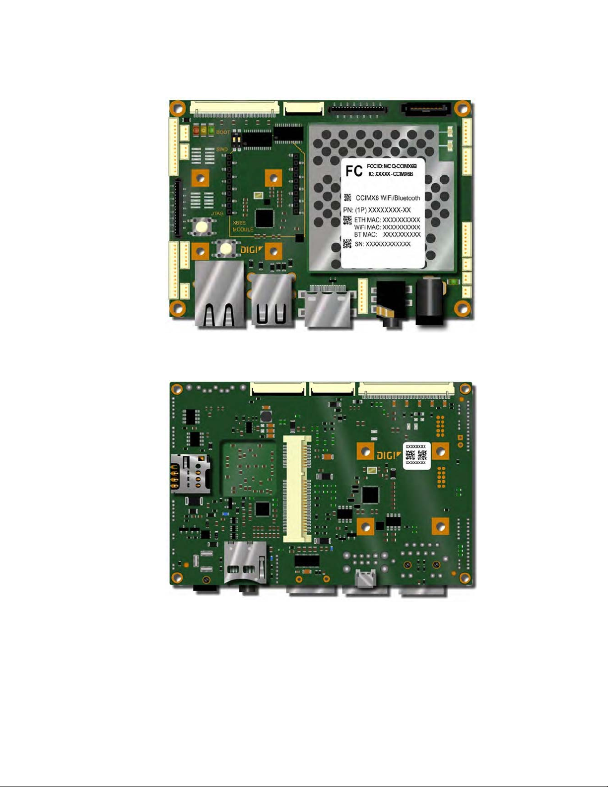
Placement - top side
Placement - bottom side
ConnectCore® for i.MX6 SBC Hardware Reference Manual
10
Page 11
ConnectCore 6 SBC overview Variants
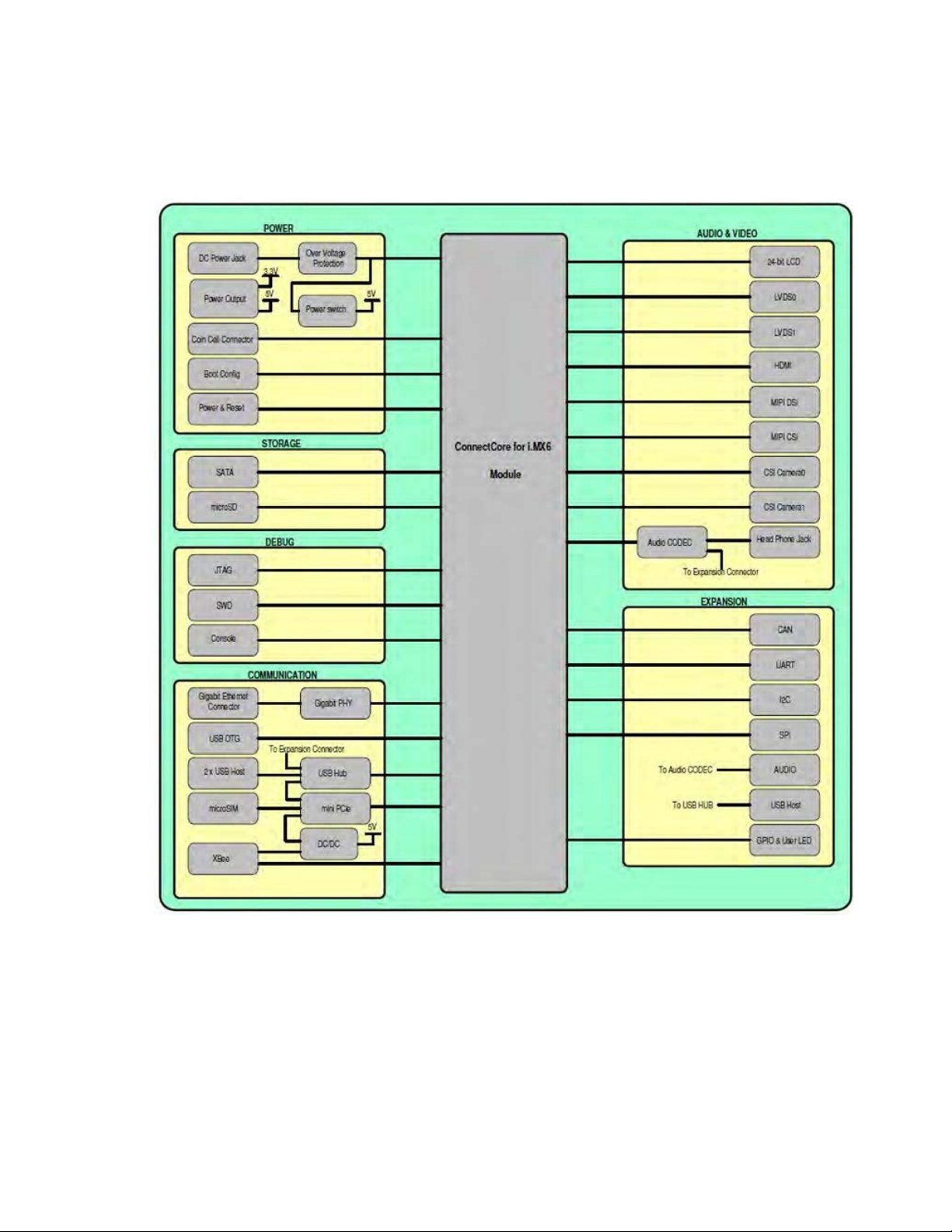
SBC block diagram
The figure below shows the block diagram of the ConnectCore 6 SBC.
ConnectCore for i.MX6 Single Board Computer
Variants
See the Digi ConnectCore 6 product page for a list of variants.
ConnectCore® for i.MX6 SBC Hardware Reference Manual
11
Page 12

ConnectCore 6 SBC interfaces
DC-in connector 13
SBC coin cell connector 15
SBC boot configuration 16
Power and reset functions 20
5V supply connector 20
3.3V supply connector 21
JTAG 21
SWD 23
SBC console port 24
SATA 26
microSD 27
Gigabit Ethernet 28
USB OTG 31
USB host 32
PCI express mini card 34
SBC micro-SIM card slot 38
XBee 39
Parallel display 41
LVDS 44
HDMI 47
MIPI display 49
MIPI camera 51
Parallel camera 53
Audio 56
CAN 58
UART 60
I2C 62
SPI 64
GPIO and user LEDs 65
ConnectCore® for i.MX6 SBC Hardware Reference Manual
12
Page 13
ConnectCore 6 SBC interfaces DC-in connector
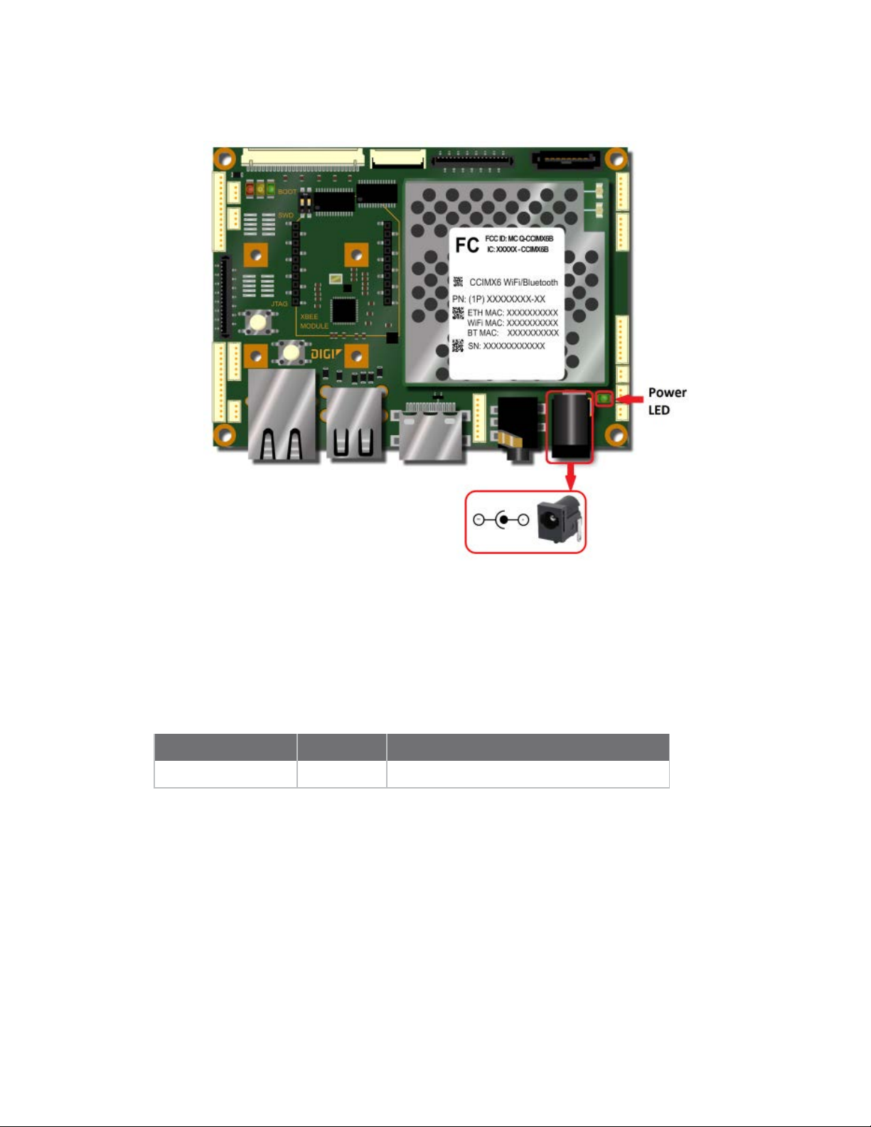
DC-in connector
The ConnectCore 6 SBC has a +5V DC-In power connector (J1) to provide power to the system. A DCJack connector is used to connect the DC-In power supply.
Power LED
A green LED near the power connector shows the status of the power input. This LED is ON when a
valid power supply is present. If the power supply voltage is higher than 5.5V the overvoltage
protection circuit will block the power supply input and the power LED will turn off.
LED
POWER VSYS Green LED
Signal Note
ConnectCore® for i.MX6 SBC Hardware Reference Manual
13
Page 14
ConnectCore 6 SBC interfaces DC-in connector
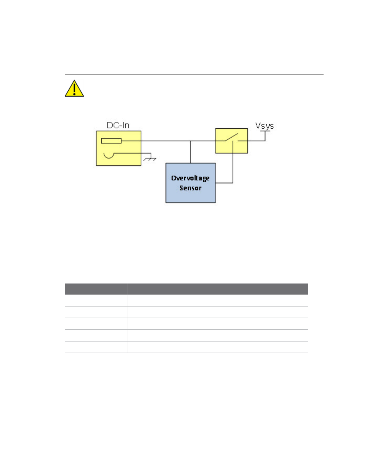
Overvoltage protection
An overvoltage protection circuit is implemented on the ConnectCore 6 SBC. If the voltage value of the
DC-In supply signal is higher than 5.5V the supply input is disconnected of the system.
CAUTION! The maximum input voltage of the ConnectCore 6 SBC should never exceed the 12
VDC. Voltages over this limit may cause permanent damage to the board.
5V load switch
The ConnectCore 6 SBC has several interfaces that have to be powered from a 5V supply. This supply
comes from a Load switch, whose input comes directly from the DC Power Jack showed above. The
SIP32401A is a slew rate controlled load switch designed for 1.1V to 5.5V operation. The SIP32401A
features a low voltage control logic interface which is commanded by the PWR_EN signal (PMIC_
GPIO7). On low power mode this load switch will be disabled. The following table lists the interfaces of
the ConnectCore 6 SBC that are sourced from the Load switch.
Interface Comments
LVDS0 Supply for the backlight of the LVDS0 display
LVDS1 Supply for the backlight of the LVDS1 display
HDMI Supply for the HDMI display
Parallel display Supply for the parallel display
5V power connector Supply for external circuitry
ConnectCore® for i.MX6 SBC Hardware Reference Manual
14
Page 15
ConnectCore 6 SBC interfaces SBC coin cell connector
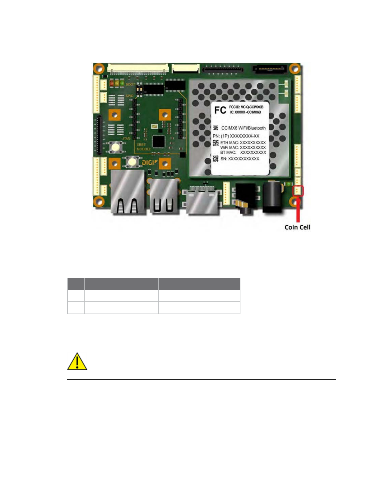
SBC coin cell connector
The ConnectCore 6 SBC provides a 2-pin, 1.25mm pitch straight connector for connecting an external
coin cell or super capacitor to power the RTC interface when the main supply is off. If higher voltage is
present on the main supply, it will be used as a power source for the RTC.
The following table shows the pinout of the coin cell connector.
Pin Signal Comments
1 VCC_LICELL Power supply for RTC
2 GND Ground
There are three types of components that can be connected to this connector: lithium coin cells
(primary cell: non-rechargeable), lithium coin cells (secondary cell: rechargeable), and supercaps.
CAUTION! When a primary lithium coin cell is connected, the PMIC backup battery charger
must be turned off and this pin is used strictly as an input. It is hazardous to attempt to
charge primary lithium cells as they may vent or explode.
Secondary lithium coin cells are only made available directly to manufacturers of equipment that could
use them. Manufacturers are normally required to design products to prevent users from gaining
access to this part. This is because there is a danger to the user if by replacing it, they fit a primary
type (the only sort that they are likely to be able to source) into the charging circuit. When a secondary
lithium coin cell is used, both the charging current and the termination voltage are programmable.
When a supercap is used, both the charge current and termination voltage should be set to the
maximum values.
ConnectCore® for i.MX6 SBC Hardware Reference Manual
15
Page 16
ConnectCore 6 SBC interfaces SBC boot configuration
The advantage of using a primary lithium coin cell is that the energy density usually allows years of
service since the self- discharge rate is low. The advantage of using a secondary lithium coin cell is
that the self-discharge rate is usually sufficient to allow a few months of support for the RTC before it
must be recharged. The advantage of the supercap is that it is intrinsically safe and can out-last the
primary lithium coin cell option. However, the self discharge rate is high, meaning that a 1F capacitor
at 25° C is likely to support the RTC for approximately five to ten days.
A programmable constant charge current charger with a programmable top-off charging voltage is
provided for charging of secondary lithium-manganese coin cell batteries and super capacitors.
Charging current is programmable from 100uA to 6mA. Termination voltage is programmable from
+1.1 to +3.1V.
The minimum voltage of the coin cell supply is +2V. The maximum voltage of the coin cell supply is
+3.6V.
Note Connector part number: MOLEX 53047-0210
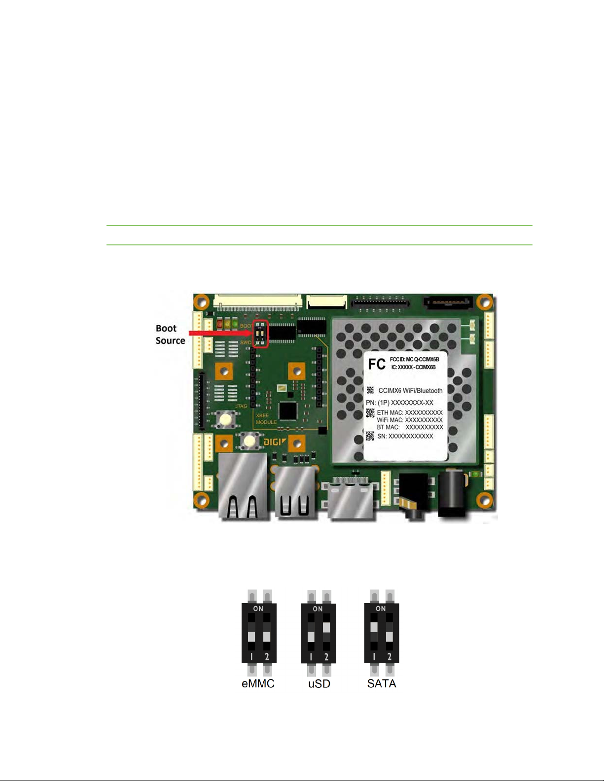
SBC boot configuration
SBC boot source switches
The ConnectCore 6 SBC provides the following switches to configure the boot source.
ConnectCore® for i.MX6 SBC Hardware Reference Manual
16
Page 17
ConnectCore 6 SBC interfaces SBC boot configuration
Pos1 Pos2 Comments
Off Off Boot from eMMC
Off On Boot from microSD
On Off Boot from SATA
On On Reserved
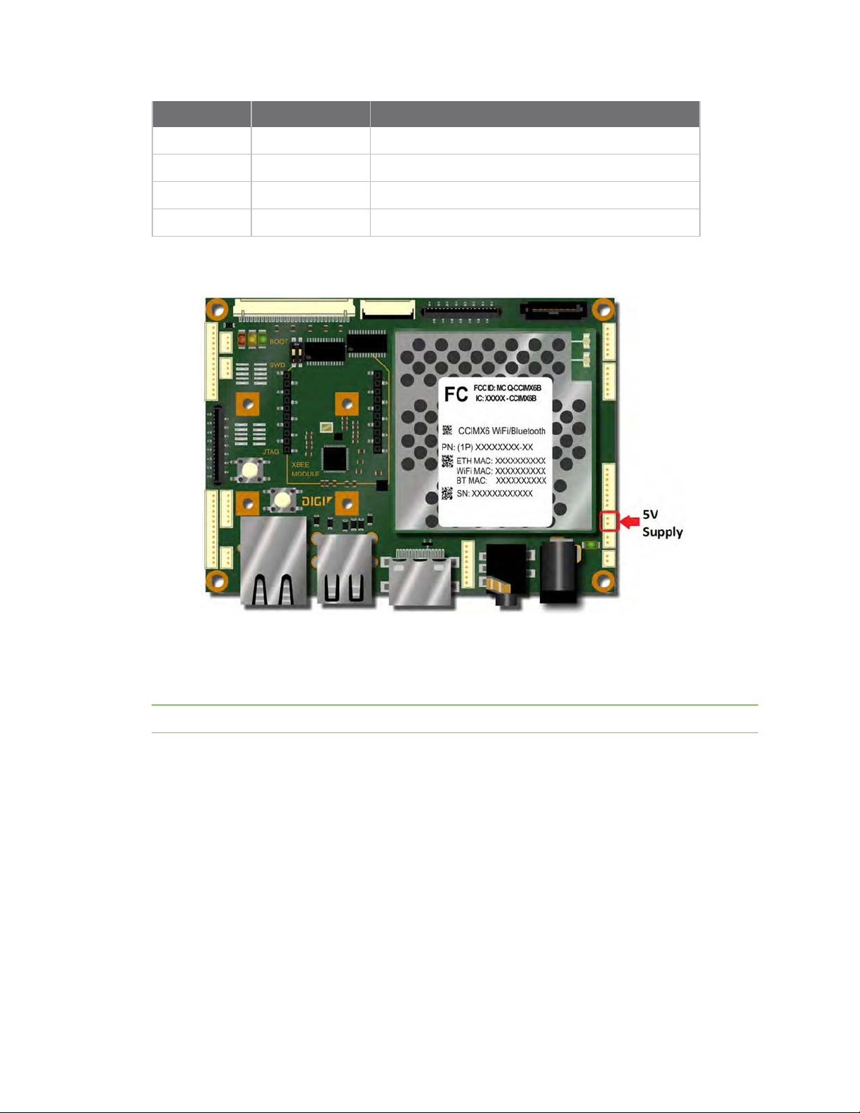
5V supply connector
The ConnectCore 6 SBC provides a 2-pin, 1.25mm pitch straight connector with a regulated 5V supply
for powering external circuitry. The 5V supply is generated on the on-board 5V regulator and it is also
used on the ConnectCore 6 SBC on the USB, displays and camera interfaces. The maximum current
available on the 5V connector is 1A.
Note Connector part number: MOLEX 53047-0210
ConnectCore® for i.MX6 SBC Hardware Reference Manual
17
Page 18
ConnectCore 6 SBC interfaces SBC boot configuration
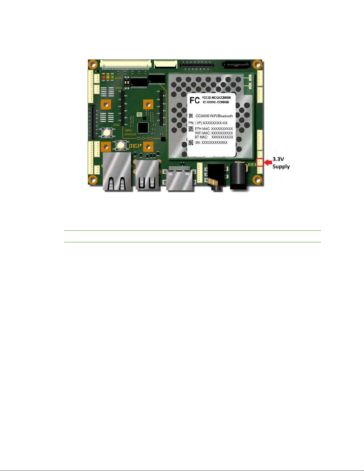
3.3V supply connector
The ConnectCore 6 SBC provides a 2-pin, 1.25mm pitch straight connector with a regulated 3.3V
supply for powering external circuitry. The 3.3V supply is generated on a buck regulator of the
ConnectCore 6 module and it is used to power several interfaces on the ConnectCore 6 module and on
the ConnectCore 6 SBC. The maximum current available on the 3.3V connector is 1A.
Note Connector part number: MOLEX 53047-0210
ConnectCore® for i.MX6 SBC Hardware Reference Manual
18
Page 19
ConnectCore 6 SBC interfaces SBC boot configuration
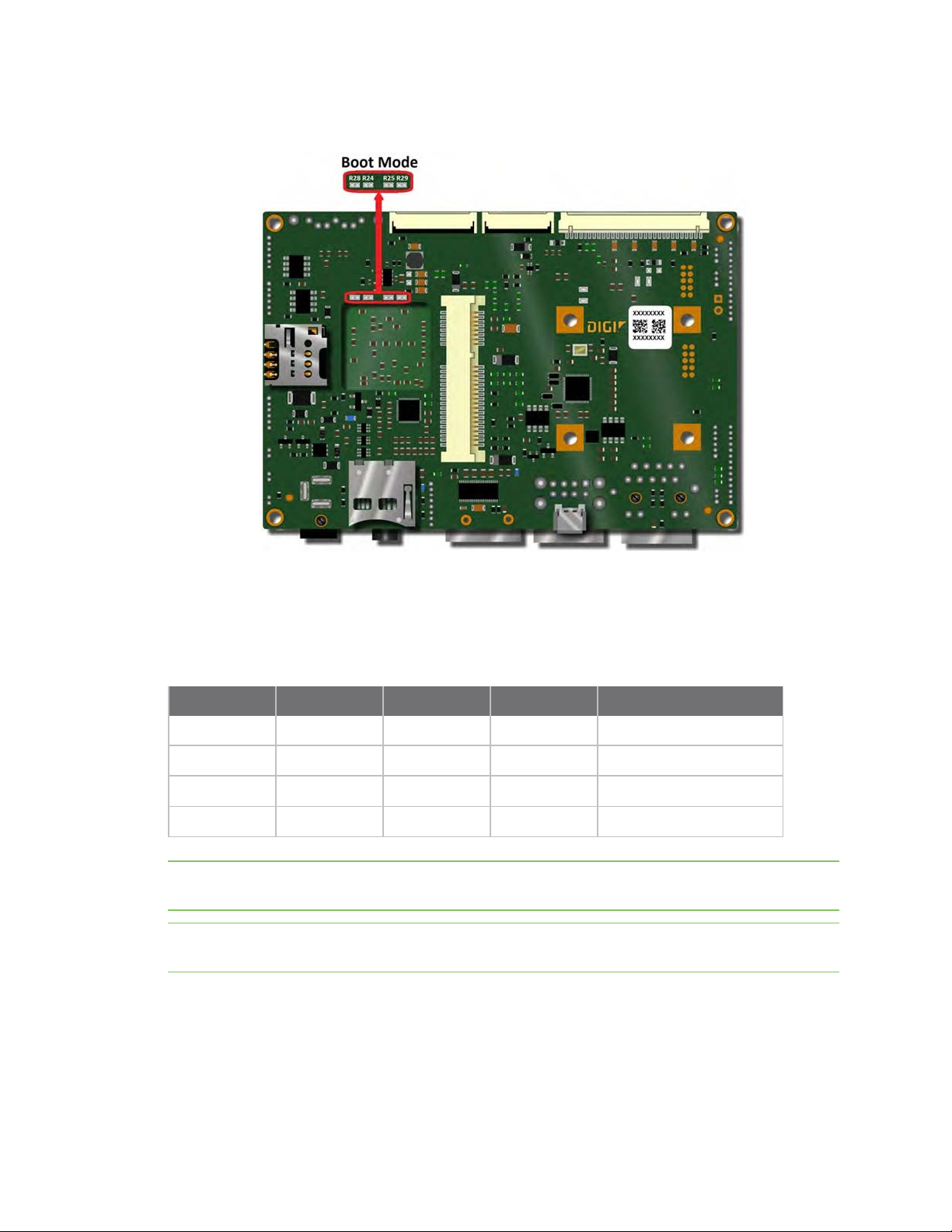
Boot mode
ConnectCore 6 SBC provides four resistors to configure the boot mode. These resistors are used to
override the boot mode configuration selected on the ConnectCore 6 module. By default these four
resistors are not populated and the ConnectCore 6 SBC will boot with the default boot mode selected
on the module.
The following table shows the resistors configuration for the different boot modes.
R24 R25 R28 R29 Boot mode
Not populated Not populated Not populated Not populated
Not populated Not populated Populated Populated Boot from fuses
Populated Not populated Not populated Populated Serial downloader
Not populated Populated Populated Not populated Boot from board settings
Note If no resistors are populated (default configuration on the SBC) internal 10K resistors on the
SOM will select the boot mode "Boot from board settings".
Note A different resistor configuration than the ones listed on the table might prevent the
ConnectCore 6 SBC from booting.
Module default boot mode
ConnectCore® for i.MX6 SBC Hardware Reference Manual
19
Page 20
ConnectCore 6 SBC interfaces Power and reset functions
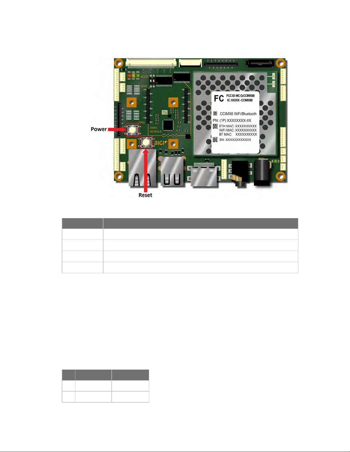
Power and reset functions
The ConnectCore 6 SBC provides a Power button that supports the following functionality:
Function Description
Power On Short press when the board is OFF.
Power Off Long press for 10 seconds when the board is ON or in SLEEP mode.
Wake-up Short press when the board is in SLEEP mode.
Sleep Short press when the board is ON.
The ConnectCore 6 SBC provides a Reset button, used to reset the ConnectCore 6 module. When the
reset button is pressed the main power supply is disconnected, powering off all the circuitry on the
board.
5V supply connector
The ConnectCore 6UL provides a 2-pin, 1.25 mm pitch straight connector with a regulated 5V supply
for powering external circuitry. The 5V supply is generated on the on-board 5V regulator, which is also
used internally in the ConnectCore 6UL SBC for powering interfaces such as the displays (LCD and
LVDS) and the USB VBUS.
The following table shows the pinout of the 5V supply connector.
Pin Signal name Description
1 5V 5V power line
2 GND
ConnectCore® for i.MX6 SBC Hardware Reference Manual
20
Page 21
ConnectCore 6 SBC interfaces 3.3V supply connector
3.3V supply connector
The ConnectCore 6UL provides a 2-pin, 1.25 mm pitch straight connector with a regulated 3.3V supply
for powering external circuitry. The 3.3V supply is generated on a buck regulator of the ConnectCore
6UL PMIC (3V3_EXT power domain), which is also used internally for powering many interfaces of the
ConnectCore 6UL SBC carrier board.
The following table shows the pinout of the 3.3V supply connector.
Pin Signal name Description
1 3V3 3.3V power line
2 GND
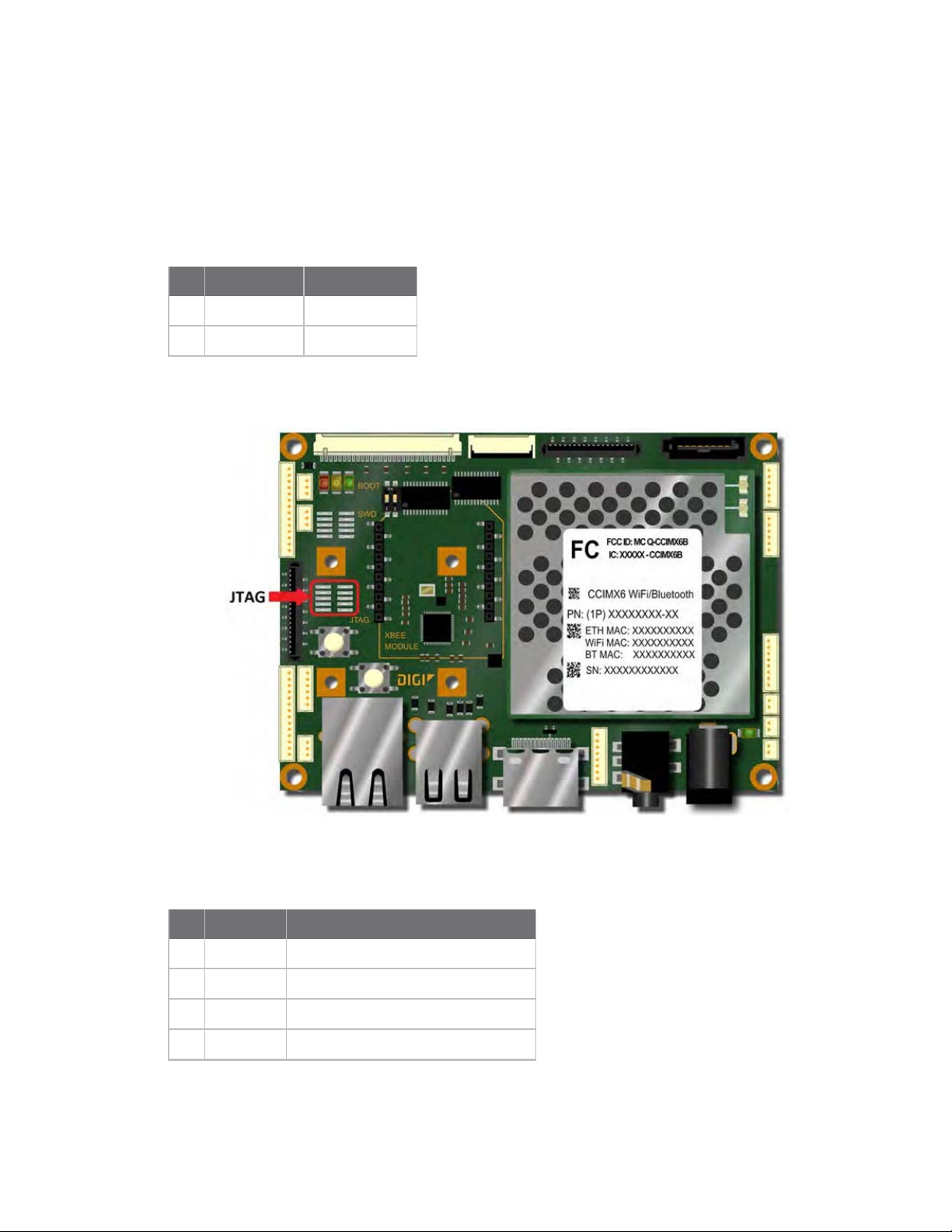
JTAG
The ConnectCore 6 SBC provides two options for accessing the i.MX6 JTAG Debug port. The first one is
a 2x5, 1.27 mm pitch pin header footprint on the top side of the board. The following table shows the
pinout of the JTAG connector.
Pin Signal Comments
1 3.3V Supply voltage of the JTAG interface
2 JTAG_TMS Test mode state signal
3 GND
4 JTAG_TCK Test clock signal
ConnectCore® for i.MX6 SBC Hardware Reference Manual
21
Page 22
ConnectCore 6 SBC interfaces JTAG
Pin Signal Comments
5 GND
6 JTAG_TDO Test data output signal
7 -
8 JTAG_TDI Test data input signal
9 GND
10 POR_N Board reset/CPU reset
Note By default, the connector is not populated.
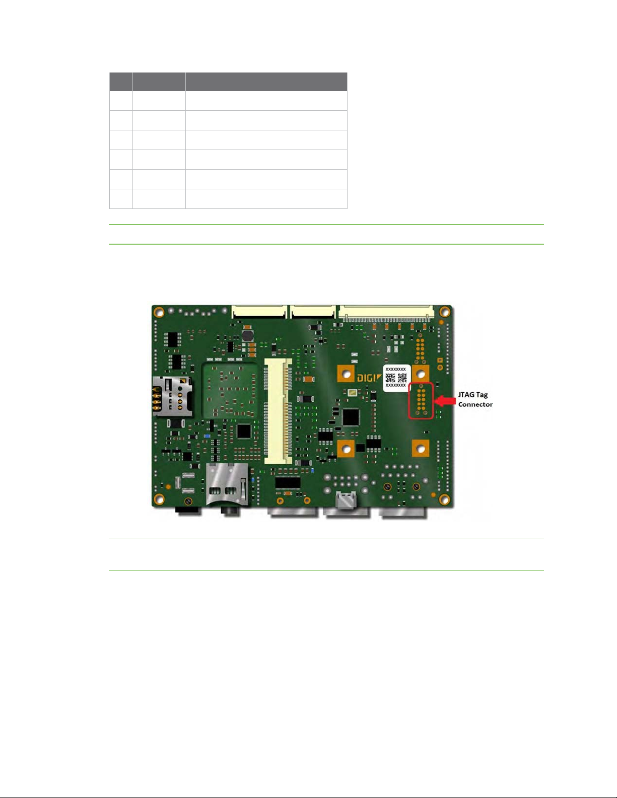
The second option is the Tag Connect footprint placed on the bottom side of the board. This Tag
Connect is compliant with the ARM 10-pin standard. The JTAG Tag Connect is highlighted in the
following picture.
Note You can use Tag-Connect’s TC2050-IDC-NL “No Legs” Plug-of-Nails™ cable (part number:
TC2050-IDC-NL) to make direct contact with the pads.
ConnectCore® for i.MX6 SBC Hardware Reference Manual
22
Page 23
ConnectCore 6 SBC interfaces SWD
SWD
The ConnectCore 6 SBC provides two options for programming and debugging the Kinetis
microcontroller assistant of the ConnectCore 6 module. The first one is a 2x5, 1.27 mm pitch pin
header footprint on the top side of the board. The following table shows the pinout of the SWD
connector.
Pin Signal Comments
1 VLDO_MCA Supply voltage of the Kinetis MCA
2 SWD_DIO SWD bidirectional data pin
3 GND
4 SWD_CLK SWD clock signal
5 GND
6 -
7 -
8 -
9 GND
10 MCA_RESET_N Reset signal for Kinetis MCA
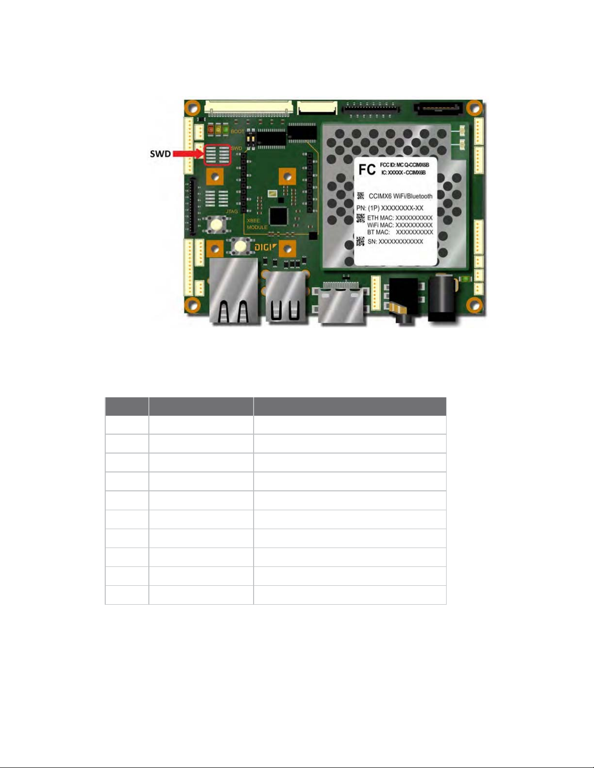
The second option is the Tag Connect footprint placed on the bottom side of the board. This Tag
connector is compliant with the ARM 10-pin standard. The SWD Tag Connect is highlighted in the
following picture.
ConnectCore® for i.MX6 SBC Hardware Reference Manual
23
Page 24

ConnectCore 6 SBC interfaces SBC console port
Note You can use Tag-Connect’s TC2050-IDC-NL “No Legs” Plug-of-Nails™ cable (part number:
TC2050-IDC-NL) to make direct contact with the pads.
SBC console port
ConnectCore® for i.MX6 SBC Hardware Reference Manual
24
Page 25

ConnectCore 6 SBC interfaces SBC console port
The ConnectCore 6 SBC provides a 3-pin, 1.25mm pitch connector for the debug console port. The
UART4 port of the ConnectCore 6 module acts as a console port. An RS-232 transceiver is used on the
SBC to convert the port to standard RS-232 levels. The following table shows the pinout of the console
connector.
Pin Signal Comments
1 CONSOLE_TX RS-232 transmission line
2 CONSOLE_RX RS-232 reception line
3 GND
Note Connector part number: MOLEX 53047-0310
ConnectCore® for i.MX6 SBC Hardware Reference Manual
25
Page 26

ConnectCore 6 SBC interfaces SATA
SATA
The ConnectCore 6 SBC provides access to the SATA interface on the ConnectCore 6 module using a
vertical SATA standard connector.
The table below provides the pinout of the SATA connector.
Pin Signal Comments
1 GND
2 SATA_TXP SATA transmission pair positive line
3 SATA_TXN SATA transmission pair negative line
4 GND
5 SATA_RXN SATA reception pair negative line
6 SATA_RXP SATA reception pair positive line
7 GND
ConnectCore® for i.MX6 SBC Hardware Reference Manual
26
Page 27

ConnectCore 6 SBC interfaces microSD
microSD
The ConnectCore 6 SBC provides a microSD connector on the bottom side. This interface is connected
to the USDHC2 controller of the i.MX6 CPU.
The microSD connector does not provide a card detect pin. A hot insertion or removal of the microSD
card is not detected by the ConnectCore 6 module. The following table shows the pinout of the
microSD connector.
Pin Signal Comments
1 SD2_DATA2
2 SD2_DATA3
3 SD2_CMD
4 3.3V
5 SD2_CLK
6 GND
7 SD2_DATA0
8 SD2_DATA1
ConnectCore® for i.MX6 SBC Hardware Reference Manual
27
Page 28

ConnectCore 6 SBC interfaces Gigabit Ethernet
Gigabit Ethernet
The ConnectCore 6 SBC provides a 10Base-T/100Base-Tx/1000Base-T Ethernet interface and uses a
Micrel KSZ9031 gigabit Ethernet PHY. The Ethernet PHY is connected to the RGMII interface of the
ConnectCore 6 module. One GPIO signal of the i.MX6 CPU is used to reset the Ethernet PHY (GPIO1_
25) and another is used as interrupt input from the PHY (GPIO1_28).
The board provides a gigabit RJ-45 connector with integrated 1:1 transformer and link/activity LEDs.
The following table shows the pinout of the gigabit connector.
Pin Signal Comments
1 TRP1+ Transmit and receive pair 1 data +
2 TRP1- Transmit and receive pair 1 data -
3 TRP2+ Transmit and receive pair 2 data +
4 TRP2- Transmit and receive pair 2 data -
5 TRP3+ Transmit and receive pair 3 data +
6 TRP3- Transmit and receive pair 3 data -
7 TRP4+ Transmit and receive pair 4 data +
8 TRP4- Transmit and receive pair 4 data -
ConnectCore® for i.MX6 SBC Hardware Reference Manual
28
Page 29

ConnectCore 6 SBC interfaces Gigabit Ethernet
Gigabit Ethernet PHY address
The ConnectCore 6 SBC has a gigabit PHY for the Ethernet interface. The address of the gigabit PHY
can be configured with four configuration resistors. The default address for the gigabit PHY is 0x0. The
following table shows the different gigabit PHY address configurations.
R53 R54 R55 R56 PHY Address
Not populated Populated Not populated Populated 0x0
Populated Not populated Not populated Populated 0x1
Not populated Populated Populated Not populated 0x2
Populated Not populated Populated Not populated 0x3
Gigabit Ethernet LEDs
The gigabit Ethernet PHY has two outputs to indicate the link and activity status of the port. These
outputs are connected to a green LED and to a yellow LED, integrated on the Ethernet connector. The
following table shows the link/activity status indicated by the two LEDs.
Yellow LED Green LED Link/Activity Status
OFF OFF Link off
ON OFF 1000 Link/No activity
Blinking OFF 1000 Link/Activity (Rx,Tx)
OFF ON 100 link/No activity
ConnectCore® for i.MX6 SBC Hardware Reference Manual
29
Page 30

ConnectCore 6 SBC interfaces Gigabit Ethernet
Yellow LED Green LED Link/Activity Status
OFF Blinking 100 Link/Activity (Rx, Tx)
ON ON 10 Link/No activity
Blinking Blinking 10 Link/Activity (Rx, Tx)
ConnectCore® for i.MX6 SBC Hardware Reference Manual
30
Page 31

ConnectCore 6 SBC interfaces USB OTG
USB OTG
The ConnectCore 6 SBC provides a micro-AB type receptacle for a USB OTG connection. This interface
can operate in Host mode and Device (peripheral) mode.
High speed, Full speed and Low speed connections are supported in Host mode. High speed and Full
speed connections are supported in peripheral mode.
When the interface is configured in Host mode, a 5V supply is connected to pin 1 (VBUS) of the USB
connector.
The following table shows the pinout of the USB OTG connector.
Pin Signal Comments
1 VBus 5V output on host mode
2 USB_DN
3 USB_DP
4 USB_ID GND for host and floating for device
5 GND
ConnectCore® for i.MX6 SBC Hardware Reference Manual
31
Page 32

ConnectCore 6 SBC interfaces USB host
USB host
The ConnectCore 6 SBC has a 4-port USB HUB that provides four USB Host interfaces. Two USB Host
interfaces are connected to a stackable dual USB A-type connector located on the front of the board.
The USB Host3 port is connected to the PCI express mini card connector. The USB Host4 port is
connected to a 6-pin, 1.25mm pitch expansion connector. All the USB ports can operate at high speed,
full speed and low speed.
The following table shows the pinout of the dual stackable USB Host connector.
Pin Signal Comments
1 USBH1_VBUS +5V
2 USBH1_DN
3 USBH1_DP
4 GND
5 USBH2_VBUS +5V
6 USBH2_DN
7 USBH2_DP
8 GND
ConnectCore® for i.MX6 SBC Hardware Reference Manual
32
Page 33

ConnectCore 6 SBC interfaces USB host
The following table shows the pinout of the USB expansion connector (J32).
Pin Signal Comments
1 +5V
2 USBH4_DP
3 USBH4_DN
4 USBH4_OC_N Over current input (low level active)
5 USBH4_PWR_EN Power enable output
6 GND
Note Connector part number: MOLEX 53047-0610
ConnectCore® for i.MX6 SBC Hardware Reference Manual
33
Page 34

ConnectCore 6 SBC interfaces PCI express mini card
PCI express mini card
The ConnectCore 6 SBC provides a Mini PCI Express connector with the following interfaces:
n PCIe transmission differential data pair
n PCIe reception differential data pair
n PCIe clock differential data pair
n I2C3
n USB Host port (USBH3)
n GPIO signal (GPIO_7_7) for the open drain, low level PCIe wake-up signal
n GPIO signal (GPIO_1_4) for the low level PCIe disable signal
n GPIO signal (GPIO_7_8) for the low level PCIe reset signal
n SIM interface
n +1.5VDC and +3.3VDC supplies
The ConnectCore 6 SBC has four 2.6mm metalized drills: two for the half size and two for the full size
mechanization. These drills have a 5.8mm x 5.8mm area without parts or routes for the screws and
nuts. Two M2.5 nuts, two M2.5 screws, two 4mm M2.5 spacers, and two M2.5 washers are needed to
install a PCI express mini card on the ConnectCore 6 SBC.
The 3.3 V power supply of the PCI Express interface comes from the MP2316 regulator. This device
features an adjustable regulator from 0.6 V from inputs within 4V and 19V. The MP2316’s input comes
directly from the DC Power Jack, offering at its output a maximum 3 A current. This regulator can be
commanded by the PCIe_VCC_EN signal (i.MX6 GPIO6_IO10). On low power mode, this device will be
disabled.
ConnectCore® for i.MX6 SBC Hardware Reference Manual
34
Page 35

ConnectCore 6 SBC interfaces PCI express mini card
The following picture shows the ConnectCore 6 SBC with a full size PCI express mini card assembled.
The following picture shows the ConnectCore 6 SBC with a half size PCI express mini card assembled.
The following table shows the pinout of the PCI express mini card connector.
Pin Signal Comments
1 PCIE_WAKE_N Connected to i.MX6 GPIO_7_7
2 +3.3V
3 -
4 GND
ConnectCore® for i.MX6 SBC Hardware Reference Manual
35
Page 36

ConnectCore 6 SBC interfaces PCI express mini card
Pin Signal Comments
5 -
6 1.5V
7 -
8 PCIE_UIM_PWR Power supply for SIM card
9 GND
10 PCIE_UIM_DATA Data for SIM card
11 PCIE_CLK_N
12 PCIE_UIM_CLK Clock for SIM card
13 PCIE_CLK_P
14 PCI_UIM_RESET Reset signal for SIM card
15 GND
16 PCIE_UIM_VPP Power supply for SIM programming
17 -
18 GND
19 -
20 PCIE_DIS_N Connected to i.MX6GPIO_1_4
21 GND
22 PCIE_RESET_N Connected to i.MX6GPIO_7_8
23 PCIE_RX_N
24 +3.3V
25 PCIE_RX_P
26 GND
27 GND
28 +1.5V
29 GND
30 I2C3_SCL
31 PCIE_TX_N
32 I2C3_SDA
33 PCIE_TX_P
34 GND
ConnectCore® for i.MX6 SBC Hardware Reference Manual
36
Page 37

ConnectCore 6 SBC interfaces PCI express mini card
Pin Signal Comments
35 GND
36 USBH3_DN
37 GND
38 USBH3_DP
39 +3.3V
40 -
41 +3.3V
42 -
43 GND
44 -
45 -
46 -
47 -
48 +1.5V
49 -
50 GND
51 -
52 +3.3V
ConnectCore® for i.MX6 SBC Hardware Reference Manual
37
Page 38
ConnectCore 6 SBC interfaces SBC micro-SIM card slot
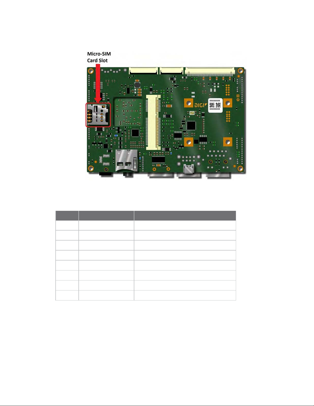
SBC micro-SIM card slot
The ConnectCore 6 SBC provides a micro-SIM card slot located on the bottom side of the board. The
SIM interface is connected to the PCIe mini card connector enabling a cellular communication when a
cellular module is installed in the Mini Card connector. The pinout of the SIM card slot is shown below.
Pin Signal Comments
1 PCIE_UIM_PWR Power supply for SIM card
2 PCI_UIM_RST Reset signal for SIM card
3 PCIE_UIM_CLK Clock signal for SIM
4 -
5 GND
6 PCIE_UIM_VPP Power supply for SIM programming
7 PCIE_UIM_DATA Data signal for SIM card
8 -
ConnectCore® for i.MX6 SBC Hardware Reference Manual
38
Page 39

ConnectCore 6 SBC interfaces XBee
XBee
The ConnecCore 6 SBC provides two 10-pin, 2mm pitch connectors to connect a Digi XBee/XBee Pro
module. The XBee identification and association signals are connected to a 3-pin, 1.25mm pitch
expansion connector.
The UART5 port of the ConnectCore 6 module is used to communicate with the XBee module. This
UART port is also connected to the UART expansion connector. Only one of the two UART5 interfaces
(XBee or Expansion) can be used at a time.
USB Host port 4 coming from the on-board USB Hub is connected to the XBee module socket. This
port allows to support USB capable XBee modules. USB Host port 4 is shared between XBee socket
and dedicated USB extension header (J32). Only one of the two location can be used at a time.
Three GPIO signals of the ConnectCore 6 module are used to reset the XBee, and control the status of
the XBee module.
The pinout of the XBee module connectors is shown below.
Pin Signal Comments
1 PCIe_VCC Dedicated DC/DC regulator(U23 - MP2316)
2 UART5_RX XBee Data Out
3 UART5_TX
4 -
5 XBEE_RESET_N Reset signal connected to GPIO_3_28
6 -
ConnectCore® for i.MX6 SBC Hardware Reference Manual
39
Page 40

ConnectCore 6 SBC interfaces XBee
Pin Signal Comments
7 USBH4_D_P Support for USB-capable XBee modules
8 USBH4_D_N Support for USB-capable XBee modules
9 XBEE_SLEEP_RQ Sleep request signal connected to GPIO_3_29
10 GND
11 -
12 UART5_RTS_N
13 XBEE_ON/SLEEP_N Status signal connected GPIO_3_27
14 -
15 XBEE_ASSOC Association signal connected to expansion connector
16 UART5_CTS_N
17 -
18 -
19 -
20 XBEE_IDENT Ident input signal connected to expansion connector
The pinout of the XBee expansion connectors are shown below.
Pin Signal Comments
1 XBEE_IDENT XBee ident input signal
2 XBEE_ASSOC XBee association output signal
3 GND XBee Data In
CAUTION! The XBee socket is powered through an external DC/DC regulator(U23 - MP2316).
The purpose of this external regulator is to provide higher current than using 3V3 supply
coming from the ConnectCore 6 module. Disabling this regulator doesn't guarantee that
the XBee socket is fully disconnected from the module. In fact, some current travels
through the I/Os to the module even after the regulator is disabled.
If your design requires fully disconnecting the XBee socket from the ConnectCore 6 module,
Digi recommends you use bus switches for all I/Os connected to the XBee socket.
CAUTION! Do not expose any XBee socket pins to 5V unless it is specifically allowed by the
XBee model.
ConnectCore® for i.MX6 SBC Hardware Reference Manual
40
Page 41

ConnectCore 6 SBC interfaces Parallel display
Parallel display
The ConnectCore 6 SBC provides a 24-bit RGB LCD interface connected to a 40-pin, 0.5mm pitch, FFC
connector. Backlight control signal, I2C port and interrupt line for a touch screen panel are available
on the parallel LCD connector. The connector has 3.3V supply for the LCD display and a 5V supply for
the LED backlight.
The pinout of the parallel display connectors is shown below.
Signal
Pin
name Description
1 GND
2 DISP0_
DAT0
3 DISP0_
DAT1
4 DISP0_
DAT2
5 DISP0_
DAT3
6 DISP0_
DAT4
7 DISP0_
DAT5
Ground
Display data line 0 B[0] B[0]
Display data line 1 B[1] B[1]
Display data line 2 B[2] B[2]
Display data line 3 B[3] B[3]
Display data line 4 B[4] B[4]
Display data line 5 B[5] B[5]
18-bit
(RGB)
24-bit
(RGB) Comments
ConnectCore® for i.MX6 SBC Hardware Reference Manual
41
Page 42

ConnectCore 6 SBC interfaces Parallel display
Signal
Pin
name Description
8 DISP0_
DAT6
9 DISP0_
DAT7
10 DISP0_
DAT8
11 DISP0_
DAT9
12 DISP0_
DAT10
13 DISP0_
DAT11
14 DISP0_
DAT12
15 DISP0_
DAT13
16 DISP0_
DAT14
18-bit
(RGB)
Display data line 6 G[0] B[6]
Display data line 7 G[1] B[7]
Display data line 8 G[2] G[0]
Display data line 9 G[3] G[1]
Display data line 10 G[4] G[2]
Display data line 11 G[5] G[3]
Display data line 12 R[0] G[4]
Display data line 13 R[1] G[5]
Display data line 14 R[2] G[6]
24-bit
(RGB) Comments
17 DISP0_
DAT15
18 DISP0_
DAT16
19 DISP0_
DAT17
20 DISP0_
DAT18
21 DISP0_
DAT19
22 DISP0_
DAT20
23 DISP0_
DAT21
24 DISP0_
DAT22
25 DISP0_
DAT23
Display data line 15 R[3] G[7]
Display data line 16 R[4] R[0]
Display data line 17 R[5] R[1]
Display data line 18 - R[2]
Display data line 19 - R[3]
Display data line 20 - R[4]
Display data line 21 - R[5]
Display data line 22 - R[6]
Display data line 23 - R[7]
ConnectCore® for i.MX6 SBC Hardware Reference Manual
42
Page 43

ConnectCore 6 SBC interfaces Parallel display
Signal
Pin
name Description
26 GND
27 DISP0_CLK
28 GND
29 DISP0_
HSYNC
30 DISP0_
VSYNC
31 DISP0_
DRDY
32 DISP0_
CONTRAST
33 I2C3_SCL
34 I2C3_SDA
35 DISP0_IRQ_
N
36 GND
Ground
Display clock line
Ground
Horizontal sync line
Vertical sync line
Data validation/blank,
data enable
Contrast line
I2C clock line
I2C data line
Interrupt line
Ground
18-bit
(RGB)
24-bit
(RGB) Comments
Clock signal for the LCD
Contrast signal connected to
DI0_PIN14 on i.MX6
Low level interrupt signal from
display
37 3V3
38 3V3
39 5V
40 5V
3,3V power rail
3,3V power rail
5V power rail
5V power rail
Supply for LCD
Supply for LCD
Supply for backlight LEDs
Supply for backlight LEDs
ConnectCore® for i.MX6 SBC Hardware Reference Manual
43
Page 44

ConnectCore 6 SBC interfaces LVDS
LVDS
The ConnectCore 6 SBC provides two LVDS interfaces.
The interface LVDS0 is connected to a 20-pin, 1.25mm pitch Hirose DF14 connector. This connector
provides access to the following LVDS capabilities:
ConnectCore® for i.MX6 SBC Hardware Reference Manual
44
Page 45

ConnectCore 6 SBC interfaces LVDS
n 4 LVDS0 differential data pairs
n 1 LVDS0 differential clock pair
n Interrupt signal (GPIO_7_11) with 10K pull-up resistors for touch screen
n PWM output (PMIC_GPIO11) to control the backlight contrast
n I2C3
n +3.3VDC and +5VDC supplies
The following table shows the pinout of the LVDS0 connector.
Pin Signal Comments
1 +3.3V
2 LVDS0 TX0 N Transmission pair 0 data -
3 LVDS0 TX0 P Transmission pair 0 data +
4 GND
5 LVDS0 TX1 N Transmission pair 1 data -
6 LVDS0 TX1 P Transmission pair 1 data +
7 GND
8 LVDS0 TX2 N Transmission pair 2 data -
9 LVDS0 TX2 P Transmission pair 2 data +
10 GND
11 LVDS0 CLK N Transmission pair clock -
12 LVDS0 CLK P Transmission pair clock +
13 GND
14 LVDS0 TX3 N Transmission pair 3 data -
15 LVDS0 TX3 P Transmission pair 3 data +
16 LVDS0 CONTRAST PMIC GPIO11
17 I2C3 SCL
18 I2C3 SDA
19 LVDS0 IRQ N Connected to i.MX6 GPIO 7 11
20 +5V
The interface LVDS1 is connected to a 20-pin, 1.25mm pitch Hirose DF14 connector. This connector
provides access to the following LVDS capabilities:
n 4 LVDS1 differential data pairs
n 1 LVDS1 differential clock pair
n Interrupt signal (GPIO_3_23) with 10K pull-up resistors for touch screen
ConnectCore® for i.MX6 SBC Hardware Reference Manual
45
Page 46

ConnectCore 6 SBC interfaces LVDS
n PWM output (PMIC_GPIO15) to control the backlight contrast
n I2C3
n +3.3VDC and +5VDC supplies
The table below shows the pinout of the LVDS1 expansion connector.
Pin Signal Comments
1 +3.3V
2 LVDS1 TX0 N Transmission pair 0 data -
3 LVDS1 TX0 P Transmission pair 0 data +
4 GND
5 LVDS1 TX1 N Transmission pair 1 data -
6 LVDS1 TX1 P Transmission pair 1 data +
7 GND
8 LVDS1 TX2 N Transmission pair 2 data -
9 LVDS1 TX2 P Transmission pair 2 data +
10 GND
11 LVDS1 CLK N Transmission pair clock -
12 LVDS1 CLK P Transmission pair clock +
13 GND
14 LVDS1 TX3 N Transmission pair 3 data -
15 LVDS1 TX3 P Transmission pair 3 data +
16 LVDS1 CONTRAST PMIC GPIO11
17 I2C3 SCL
18 I2C3 SDA
19 LVDS1 IRQ N Connected to i.MX6 GPIO3_23
20 +5V
ConnectCore® for i.MX6 SBC Hardware Reference Manual
46
Page 47

ConnectCore 6 SBC interfaces HDMI
HDMI
The ConnectCore 6 module provides an HDMI 1.4a compatible interface. The interface includes the
HDMI controller and PHY. Video resolutions up to 1080p at 120Hz HDTV are supported. All audio
formats as specified by the HDMI Specification 1.4 are supported. Hot plug/unplug detection is also
supported.
The ConnectCore 6 SBC board provides an HDMI connector for a standard HDMI cable. The HDMI
interface includes ESD, overcurrent and backdrive protection.
The table below shows the pinout of the HDMI connector.
Pin Signal Comments
1 HDMI_TX2_P+ Transmission pair 2 data +
2 GND Data2 shield
3 HDMI_TX2_N - Transmission pair 2 data -
4 HDMI_TX1_P + Transmission pair 1 data +
5 GND Data1 shield
6 HDMI_TX1_N - Transmission pair 1 data -
7 HDMI_TX0_P + Transmission pair 0 data +
8 GND Data0 shield
ConnectCore® for i.MX6 SBC Hardware Reference Manual
47
Page 48

ConnectCore 6 SBC interfaces HDMI
Pin Signal Comments
9 HDMI_TX0_N - Transmission pair 0 data -
10 HDMI_TXC_P + Transmission pair clock +
11 GND Clock shield
12 HDMI_TXC_N - Transmission pair clock -
13 HDMI_CEC Consumer Electric Control
14 NC Reserved
15 HDMI_SCL I2C SCL
16 HDMI_SDA I2C SDA
17 GND DDC/CEC Ground
18 +5V 5V supply (50mA max)
19 HOTPLUG_DET Hot Plug Detection
ConnectCore® for i.MX6 SBC Hardware Reference Manual
48
Page 49

ConnectCore 6 SBC interfaces MIPI display
MIPI display
The ConnectCore 6 SBC provides a MIPI display serial interface (MIPI_DSI) compliant with the MIPI
DSI specification. A MIPI D-PHY is included on the module, allowing direct connections between the
module and a MIPI DSI compliant display.
The MIPI DSI interface is connected to a 15-pin, 1mm pitch, FCC connector on the top side of the
ConnectCore 6 SBC. This connector provides access to the following signals:
n 2 MIPI DSI differential data pairs
n 1 MIPI DSI differential clock pair
n I2C3
n +3.3VDC
The table below shows the pinout of the MIPI display connector.
Pin Signal Comments
1 +3.3V
2 +3.3V
3 GND
4 I2C3_SDA
5 I2C3_SCL
6 GND
ConnectCore® for i.MX6 SBC Hardware Reference Manual
49
Page 50

ConnectCore 6 SBC interfaces MIPI display
Pin Signal Comments
7 DSI_D0_P MIPI Display pair 0 data+
8 DSI_D0_N MIPI Display pair 0 data-
9 GND
10 DSI_CLK_P MIPI Display pair clock+
11 DSI_CLK_N MIPI Display pair clock-
12 GND
13 DSI_D1_P MIPI Display pair 1 data+
14 DSI_D1_N MIPI Display pair 1 data-
15 GND
ConnectCore® for i.MX6 SBC Hardware Reference Manual
50
Page 51

ConnectCore 6 SBC interfaces MIPI camera
MIPI camera
The ConnectCore 6 SBC provides a MIPI camera serial interface (MIPI CSI) compliant with the MIPI
CSI-2 specification. A MIPI D-PHY is included on the module, allowing direct connections between the
module and a MIPI CSI-2 compliant camera sensor.
The MIPI CSI interface is connected to a 15-pin, 1mm pitch, FCC connector on the top side of the
ConnectCore 6 SBC. This connector provides access to the following signals:
n 2 MIPI CSI differential data pairs
n 1 MIPI CSI differential clock pair
n MIPI Camera Reset signal (GPIO7_6)
n I2C3
n +3.3VDC
The table below shows the pinout of the MIPI CSI connector.
Pin Signal Comments
1 +3.3V
2 I2C3_SDA
3 I2C3_SCL
4 -
ConnectCore® for i.MX6 SBC Hardware Reference Manual
51
Page 52

ConnectCore 6 SBC interfaces MIPI camera
Pin Signal Comments
5 CSI_RESET_N Connected to i.MX6 GPIO_7_6
6 GND
7 CSI_CLK_P MIPI CSI pair clock+
8 CSI_CLK_N MIPI CSI pair clock -
9 GND
10 CSI_D1_P MIPI CSI pair 1 data+
11 CSI_D1_N MIPI CSI pair 1 data-
12 GND
13 CSI_D0_P MIPI CSI pair 0 data+
14 CSI_D0_N MIPI CSI pair 0 data-
15 GND
ConnectCore® for i.MX6 SBC Hardware Reference Manual
52
Page 53
ConnectCore 6 SBC interfaces Parallel camera
Parallel camera
ConnectCore® for i.MX6 SBC Hardware Reference Manual
53
Page 54

ConnectCore 6 SBC interfaces Parallel camera
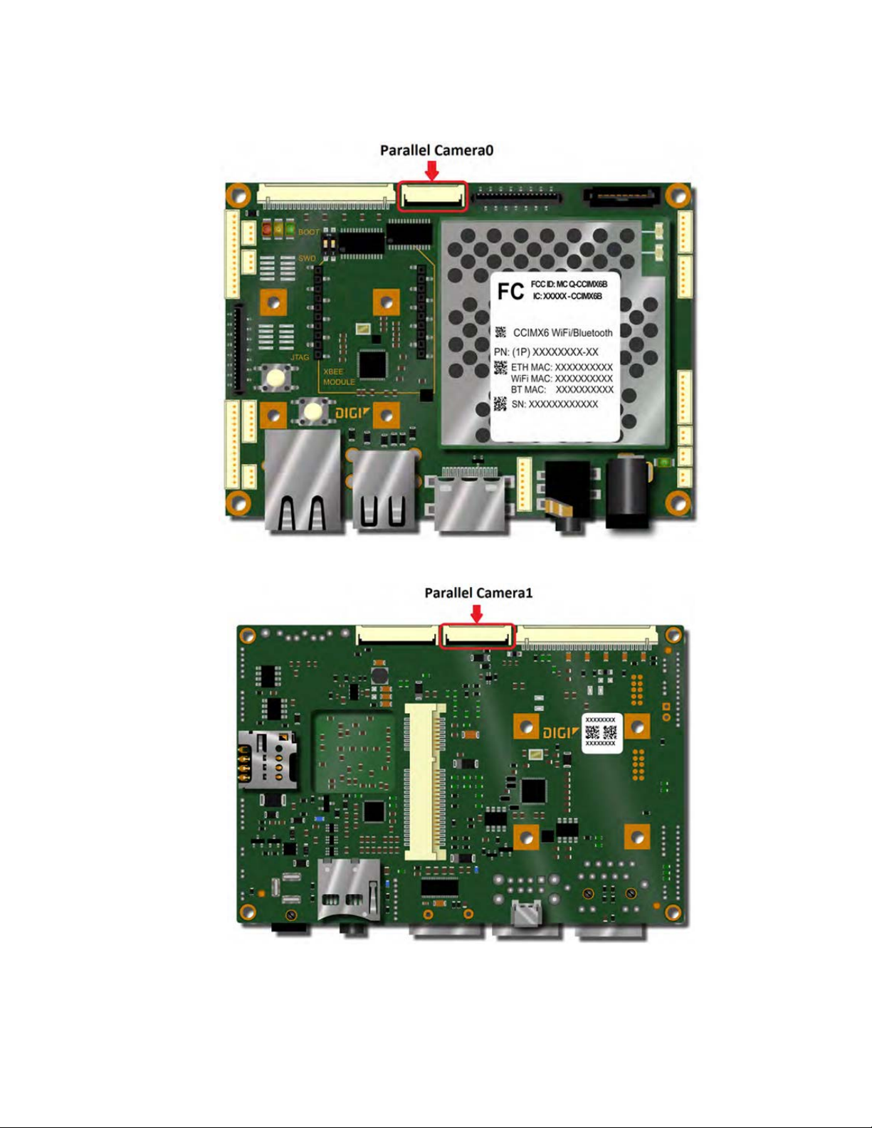
The ConnectCore 6 SBC provides two parallel camera sensor interfaces (CSI). Both interfaces are
composed of an 8-bit data bus, a master clock generated by the i.MX6 CPU and three synchronization
signals (PIXCLK, HSYNV and VSYNC) generated by the camera sensor.
The first parallel camera interface is connected to a 20-pin FFC connector. This connector provides
access to the following signals:
n 8-bit data bus (CSI0_D12 to CSI0_D19)
n Master clock (CSI0_MCLK)
n Pixel clock (CSI0_PIXCLK)
n Horizontal synchronization (CSI0_HSYNC)
n Vertical synchronization (CSI0_VSYNC)
n Camera reset signal (CSI0_RESET_N) connected to GPIO5_0 on the i.MX6 CPU
n I2C3
n GPIO signal (GPIO_5_20)
The table below shows the pinout of the CSI0 connector.
Pin Signal Comments
1 GND
2 CSI0_DAT12 Lowest significant data bit
3 CSI0_DAT13
4 CSI0_DAT14
5 CSI0_DAT15
6 CSI0_DAT16
7 CSI0_DAT17
8 CSI0_DAT18
9 CSI0_DAT19 Highest significant data bit
10 GND
11 CSI0_MCLK
12 CSI0_PIXCLK
13 CSI0_HSYNC
14 CSI0_VSYNC
15 CSI0_GPIO
16 CSI0_RESET_N
17 GND
18 I2C3_SCL
19 I2C3_SDA
20 3.3V
ConnectCore® for i.MX6 SBC Hardware Reference Manual
54
Page 55

ConnectCore 6 SBC interfaces Parallel camera
The second parallel camera interface is connected to a 20-pin, 0.5mm pitch, FCC connector located on
the bottom side of the board. This connector provides access to the following signals:
n 8-bit data bus (CSI1_D12 to CSI1_D19)
n Master clock (CSI1_MCLK)
n Pixel clock (CSI1_PIXCLK)
n Horizontal synchronization (CSI1_HSYNC)
n Vertical synchronization (CSI1_VSYNC)
n Camera reset signal (CSI1_RESET_N) connected to GPIO3_15 on the i.MX6 CPU
n I2C3
n GPIO signal (GPIO5_2)
The table below shows the pinout of the CSI1 connector.
Pin Signal Comments
1 GND
2 CSI1_DAT12 Lowest significant data bit
3 CSI1_DAT13
4 CSI1_DAT14
5 CSI1_DAT15
6 CSI1_DAT16
7 CSI1_DAT17
8 CSI1_DAT18
9 CSI1_DAT19 Highest significant data bit
10 GND
11 CSI1_MCLK
12 CSI1_PIXCLK
13 CSI1_HSYNC
14 CSI1_VSYNC
15 CSI1_GPIO
16 CSI1_RESET_N
17 GND
18 I2C3_SCL
19 I2C3_SDA
20 3.3V
ConnectCore® for i.MX6 SBC Hardware Reference Manual
55
Page 56

ConnectCore 6 SBC interfaces Audio
Audio
The ConnectCore 6 SBC provides an audio interface with headphone, line-out, line-in, and microphone
signals. The NXP SGTL5000 audio codec is used on the SBC to generate all the audio signals.
The headphone audio signal is connected to a stereo audio jack. The signal GPIO2_0 of the i.MX6 is
connected to the audio jack for the headphone detector functionality. When a headphone is connected
to the audio jack, the line-out channel will be muted and the CODEC will route the audio output to the
headphone. If a headphone is not connected the audio CODEC will connect the audio output to the
line-out channel.
To improve the power consumption during low power modes, the ConnectCore 6 SBC provides a
circuit to switch off the power supply of the audio codec. This switch is controlled with the GPIO2_25
of the i.MX6 processor. When the GPIO2_25 is at high level the audio codec is powered. When the
GPIO2_25 is at low level the audio codec is not powered.
The table below shows the pinout of the headphone audio jack.
Pin Signal Comments
1 GND
2 HP_R Right headphone channel
3 HP_L Left headphone channel
4 -
5 HP_DET Headphone detection
ConnectCore® for i.MX6 SBC Hardware Reference Manual
56
Page 57
ConnectCore 6 SBC interfaces Audio
The line in, line out and microphone audio signals are available on an 8-pin, 1.25mm pitch expansion
connector (J26). The table below shows the pinout of the audio expansion connector.
Pin Signal Comments
1 MIC_BIAS
2 MIC_IN
3 LINE_IN_R
4 LINE_IN_L
5 GND
6 LINE_OUT_R
7 LINE_OUT_L
8 GND
Note Connector part number: MOLEX 53047-0810
ConnectCore® for i.MX6 SBC Hardware Reference Manual
57
Page 58

ConnectCore 6 SBC interfaces CAN
CAN
The ConnectCore 6 SBC provides two CAN bus ports compatible with the CAN 2.0B protocol. Two CAN
transceivers are used on the SBC to provide transmit and receive capability between the differential
CAN bus and the CAN controller of the i.MX6 CPU. These transceivers allow signal rates up to 1Mbps.
The i.MX6 signals GPIO_1_2 and GPIO_1_5 are used to put the CAN1 and CAN2 transceivers on lowpower standby mode.
The two CAN ports are available on a 6-pin, 1.25mm pitch expansion connector. The table below
shows the pinout of the CAN expansion connector.
Pin Signal
1 CAN1_L
2 CAN1_H
3 GND
4 CAN2_L
5 CAN2_H
6 GND
Note Connector part number: MOLEX 53047-0610
ConnectCore® for i.MX6 SBC Hardware Reference Manual
58
Page 59

ConnectCore 6 SBC interfaces CAN
CAN termination resistors
The ConnectCore 6 SBC provides two 120W termination resistors on the CAN interfaces. By default
these two resistors are populated.
Resistor Description
R104 CAN1 termination resistor
R116 CAN2 termination resistor
ConnectCore® for i.MX6 SBC Hardware Reference Manual
59
Page 60

ConnectCore 6 SBC interfaces UART
UART
The ConnectCore 6 SBC provides access to three UART interfaces on a 14-pin, 1.25mm pitch UART
expansion connector. This connector provides access to the following interfaces:
n UART1: 4 wire, RS-232 level UART
n UART3: 4 wire, RS-232 level UART
n UART5: 4 wire, TTL UART shared with XBee interface
These three UART interfaces have software flow control lines (RTS and CTS). UART1 and UART3 have
RS-232 levels and they are configured in DTE mode (CTS input and RTS output). The UART5 interface
has TTL levels and it is configured in DCE mode (CTS output and RTS input).
The table below shows the pinout of the UART expansion connector.
Pin Signal Comments
1 RS-232_1_TX
2 RS-232_1_RX
3 RS-232_1_RTS_N Output from i.MX6
4 RS-232_1_CTS_N Input to i.MX6
5 3.3V
6 RS-232_3_TX
7 RS-232_3_RX
8 RS-232_3_RTS_N Output from i.MX6
9 RS-232_3_CTS_N Input to i.MX6
ConnectCore® for i.MX6 SBC Hardware Reference Manual
60
Page 61

ConnectCore 6 SBC interfaces UART
Pin Signal Comments
10 GND
11 UART5_TX
12 UART5_RX
13 UART5_RTS_N Output from i.MX6
14 UART5_CTS_N Input to i.MX6
Note Connector part number: MOLEX 53047-1410
ConnectCore® for i.MX6 SBC Hardware Reference Manual
61
Page 62

ConnectCore 6 SBC interfaces I2C
I2C
The ConnectCore 6 SBC provides access to the I2C3 interface of the i.MX6 CPU. Two 2K2 pull-up
resistors to 3.3V are connected to the I2C3 lines on the SBC.
The I2C3 port is used on the ConnectCore 6 SBC on several interfaces. The following table shows the
interfaces connected to the I2C3 bus and their default I2C addresses.
Speed
Interface
HDMI EDID 100 0x50 Read only accesses
MIPI Camera - - Address depends on the camera used
MIPI Display - - Address depends on the display used
CSI0 Camera - - Address depends on the camera used
CSI1 Camera - - Address depends on the display used
PCIe mini card - - Address depends on the camera used
LVDS0 touch Address depends on the touch used
LVDS1 touch Address depends on the touch used
DIsplay0 touch Address depends on the touch used
Audio CODEC 400 0x0A Address of SGTL5000
(Kbps)
Address (7bit) Comment
I2C expansion - - Address depends on the device connected
The I2C3 port is connected to a 6-pin, 1.25mm pitch expansion connector. This connector provides
access to the following signals:
ConnectCore® for i.MX6 SBC Hardware Reference Manual
62
Page 63

ConnectCore 6 SBC interfaces I2C
n I2C3 port
n Interrupt signal connected to GPIO_6_15
n GPIO_6_16 signal
The table below shows the pinout of the I2C expansion connector.
Pin Signal Comments
1 I2C3_SCL
2 I2C3_SDA
3 3V3
4 I2C3_IRQ_N 10K pull-up to 3.3V on the SBC
5 I2C3_GPIO
6 GND
Note Connector part number: MOLEX 53047-0610
ConnectCore® for i.MX6 SBC Hardware Reference Manual
63
Page 64

ConnectCore 6 SBC interfaces SPI
SPI
The ConnectCore 6 SBC provides an SPI interface, accessible through an 8-pin, 1.25mm pitch
expansion connector. This connector provides access to the following signals:
n SPI1 interface
n One slave select signal (SPI_SS0)
n GPIO_4_10. This signal can be used as interrupt input or as SPI_SS1.
The table below shows the pinout of the SPI expansion connector.
Pin Signal Comments
1 3V3
2 SP1_CLK
3 SP1_MISO
4 SP1_MOSI
5 SP1_SS0
6 SP1_SS1
7 SP1_IRQ_N 10k pull-up resistor to 3V3 on SBC
8 GND
Note Connector part number: MOLEX 53047-0810
ConnectCore® for i.MX6 SBC Hardware Reference Manual
64
Page 65
ConnectCore 6 SBC interfaces GPIO and user LEDs
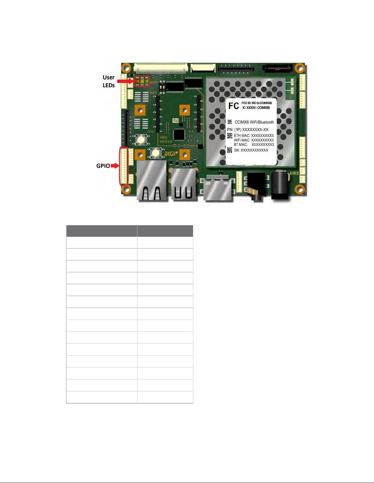
GPIO and user LEDs
The table below shows the default GPIO assignment done on the ConnectCore 6 SBC.
Signal Name GPIO
AUD_HP_DET GPIO_2_0
CAN1_STBY GPIO_1_2
CAN2_STBY GPIO_1_5
CSI_RESET_N GPIO_7_6
CSI0_GPIO GPIO_5_20
CSI0_RESET_N GPIO_5_0
CSI1_RESET_N GPIO_3_15
DISP0_IRQ_N GPIO_2_1
DSI_IRQ_N GPIO_2_27
DSI_PWR_EN GPIO_6_31
DSI_RESET_N GPIO_3_26
EXP_GPIO_3 GPIO_2_24
EXP_GPIO_4 GPIO_2_28
EXP_GPIO_5 GPIO_2_29
ConnectCore® for i.MX6 SBC Hardware Reference Manual
65
Page 66

ConnectCore 6 SBC interfaces GPIO and user LEDs
Signal Name GPIO
EXP_GPIO_6 GPIO_7_13
EXP_GPIO_7 GPIO_4_5
EXP_I2C_GPIO GPIO_6_16
EXP_I2C_IRQ_N GPIO_6_15
EXT_GPIO_0 GPIO_2_5
EXT_GPIO_1 GPIO_2_6
EXT_GPIO_2 GPIO_2_7
LVDS0_IRQ_N GPIO_7_11
LVDS1_IRQ_N GPIO_3_23
PCIE_DIS_N GPIO_1_4
PCIE_RESET_N GPIO_7_8
PCIE_WAKE_N GPIO_7_7
PWR_EN PMIC_GPIO7
RGMII_INT_N GPIO_1_28
RGMII_RESET_N GPIO_1_25
SPI1_IRQ_N GPIO_4_10
USB_HUB_RESET_N GPIO_3_10
USER_LED0 GPIO_2_2
USER_LED1 GPIO_2_3
USER_LED2 GPIO_2_4
XBEE_ON/SLEEP_N GPIO_3_27
XBEE_RESET_N GPIO_3_28
XBEE_SLEEP_RQ GPIO_3_29
The ConnectCore 6 SBC provides a 14-pin, 1.25mm pitch expansion connector with eight digital GPIO
signals of the i.MX6 CPU and four digital/analog configurable GPIO signals from the Kinetis MCA. The
following table shows the pinout of the expansion GPIO connector.
Pin Signal Comments
1 TOUCH_X1/PMIC_
ADCIN1
2 TOUCH_X2/PMIC_
ADCIN2
ConnectCore® for i.MX6 SBC Hardware Reference Manual
By default, PMIC_ADCIN1 is connected to this pin over a
0R resistor.
By default, PMIC_ADCIN2 is connected to this pin over a
0R resistor.
66
Page 67

ConnectCore 6 SBC interfaces GPIO and user LEDs
Pin Signal Comments
3 TOUCH_Y1/PMIC_
ADCIN3
4 TOUCH_Y2 MCA_IO9
5 3.3V
6 EXP_GPIO_0
7 EXP_GPIO_1
8 EXP_GPIO_2
9 EXP_GPIO_3
10 EXP_GPIO_4
11 EXP_GPIO_5
12 EXP_GPIO_6
13 EXP_GPIO_7
14 GND
Note The maximum voltage level of the analog input is 2.5V. The maximum voltage level of the digital
Input output signals is 3.3V.
By default, PMIC_ADCIN3 is connected to this pin over a
0R resistor.
Connector part number: MOLEX 53047-1410
The ConnectCore 6 SBC provides three user LEDs controlled with three GPIO signal. The color of each
user LED is different. The following table shows the GPIO associated with each user LED.
LED Signal Comments
USER_LED0 GPIO_2_2 Red LED
USER_LED1 GPIO_2_3 Yellow LED
USER_LED2 GPIO_2_4 Green LED
ConnectCore® for i.MX6 SBC Hardware Reference Manual
67
Page 68

Specifications
Electrical specifications 69
Mechanical specifications 70
Environmental specifications 71
WLAN specifications 71
Bluetooth specifications 71
ConnectCore® for i.MX6 SBC Hardware Reference Manual
68
Page 69

Electrical specifications
The following table shows the voltage range of the input supplies of the ConnectCore 6 SBC.
Supply voltages
Signal
DC-In Main DC supply 4.75 5 5.5 V
VCC_LICELL Supply for RTC 2.0 3.0 5 V
The following table shows the voltage and current specification of the supply signals generated on the
ConnectCore 6 SBC.
Signal Voltage Current
PCIe_VCC 3.3V 3000mA
5V 5V 2400mA
Note 3.3V is generated for PCIe minicard. 5V is generated through the load switch (U7).
Note Voltage at the output of the load switch (U7) depends on the current going through the switch. A
fixed 5V cannot be guaranteed.
Description Min. Typ. Max. Unit
ConnectCore® for i.MX6 SBC Hardware Reference Manual
69
Page 70

Mechanical specifications
The ConnectCore 6 SBC is a 100mm x 72mm pico-ITX board.
Four 3.2mm drills are located on the four corners of the PCB for assembling the board into an
enclosure. These drills have a 5.5mm round metalized area for the screws and nuts.
The board has four 2.6mm drills to assemble a half size or a full size PCI express mini card module.
These drills have a 5.8mm x 5.8mm square metalized area for the screws and nuts.
There must be a recess in the board to accommodate the components on the bottom side of the SOM.
All dimensions on the following pictures are in millimeters.
The maximum component height on the top side of the ConnectCore 6 SBC is 15.6mm. The maximum
component height on the bottom side of the ConnectCore 6 SBC is 6.8mm.
ConnectCore® for i.MX6 SBC Hardware Reference Manual
70
Page 71

Environmental specifications
The operating temperatures defined for the ConnectCore 6 SBC depend on the ConnectCore 6 module
variant.
Specification Operating Temperature
Industrial -40° C to +85° C
Commercial
0° C to +70° C
WLAN specifications
For a complete WLAN specification please refer to the ConnectCore for i.MX6 Hardware Reference
Manual at www.digi.com/resources/documentation/DigiDocs/PDFs/90001394.pdf.
Bluetooth specifications
For a complete Bluetooth specification please refer to the ConnectCore for i.MX6 Hardware Reference
Manual at www.digi.com/resources/documentation/DigiDocs/PDFs/90001394.pdf.
ConnectCore® for i.MX6 SBC Hardware Reference Manual
71
Page 72

Regulatory information
Maximum power and frequency specifications 73
Europe 73
Brazil 74
ConnectCore® for i.MX6 SBC Hardware Reference Manual
72
Page 73

Regulatory information Maximum power and frequency specifications
Maximum power and frequency specifications
Note The following maximum power and frequency values are for the ConnectCore 6 system on
module.
Maximum
power
17.5 mW
62.4 mW
Europe
Declarations of Conformity
Digi has issued Declarations of Conformity for the ConnectCore 6 SBC concerning emissions, EMC, and
safety. For more information, see http://www.digi.com/resources/certifications.
Important note
Digi customers assume full responsibility for learning and meeting the required guidelines for each
country in their distribution market. Refer to the radio regulatory agency in the desired countries of
operation for more information.
CE mark
The ConnectCore 6 SBC is certified for use in several European countries. For information, visit
www.digi.com/resources/certifications.
If the ConnectCore 6 SBC is incorporated into a product, the manufacturer must ensure compliance of
the final product with articles 3.1a and 3.1b of the RE Directive (Radio Equipment Directive). A
Declaration of Conformity must be issued for each of these standards and kept on file as described in
the RE Directive (Radio Equipment Directive).
Furthermore, the manufacturer must maintain a copy of the ConnectCore 6 SBC user manual
documentation and ensure the final product does not exceed the specified power ratings, antenna
specifications, and/or installation requirements as specified in the user manual. If any of these
specifications are exceeded in the final product, a submission must be made to a notified body for
compliance testing to all required standards.
Frequencies
13 overlapping channels each 22 MHz wide and spaced at 5 MHz. Centered at 2.412
to 2.472 MHz.
165 overlapping channels each 22 or 40 MHz wide and spaced at 5 MHz. Centered at
5180 to 5825 MHz.
OEM labeling requirements
The CE marking must be affixed to a visible location on the OEM product.
ConnectCore® for i.MX6 SBC Hardware Reference Manual
73
Page 74

Regulatory information Brazil
CE labeling requirements
The CE mark shall consist of the initials “CE” taking the following form:
Brazil
n If the CE marking is reduced or enlarged, the proportions given in the above graduated
drawing must be respected.
n The CE marking must have a height of at least 5mm except where this is not possible on
account of the nature of the apparatus.
n The CE marking must be affixed visibly, legibly, and indelibly.
Este equipamento não tem direito à proteção contra interferência prejudicial e não pode causar
interferência em sistemas devidamente autorizados.
ConnectCore® for i.MX6 SBC Hardware Reference Manual
74
 Loading...