

Page 1

Digi CM
8-port, 16-port, 32-port, and 48-port
User Guide
Page 2

Revision history—90000301-88
Revision Date Description
H August 2018 Added certification in French. Added power and ground information for CM
48. Updated the template.
Trademarks and copyright
Digi, Digi International, and the Digi logo are trademarks or registered trademarks in the United States and other
countries worldwide. All other trademarks mentioned in this document are the property of their respective
owners.
© 2018 Digi International. All rights reserved.
Disclaimers
Information in this document is subject to change without notice and does not represent a commitment on the
part of Digi International. Digi provides this document “as is,” without warranty of any kind, expressed or implied,
including, but not limited to, the implied warranties of fitness or merchantability for a particular purpose. Digi
may make improvements and/or changes in this manual or in the product(s) and/or the program(s) described in
this manual at any time.
Warranty
To view product warranties online, visit www.digi.com/howtobuy/terms.
Send comments
Documentation feedback: To provide feedback on this document, send your comments to
techcomm@digi.com.
Customer support
Digi Technical Support: Digi offers multiple technical support plans and service packages to help our customers
get the most out of their Digi product. For information on Technical Support plans and pricing, contact us at +1
952.912.3456 or visit www.digi.com/support.
Full book title 2
Page 3

Contents
Overview
Digi CM Model Support . . . . . . . . . . . . . . . . . . . . . . . . . . . . . . . . . . . . . . . . . . . . . . . . . . . . . . . . . . . . . . . . . . . . . . . . . . . . . . . 10
Feature overview . . . . . . . . . . . . . . . . . . . . . . . . . . . . . . . . . . . . . . . . . . . . . . . . . . . . . . . . . . . . . . . . . . . . . . . . . . . . . . . . . 10
Feature summary . . . . . . . . . . . . . . . . . . . . . . . . . . . . . . . . . . . . . . . . . . . . . . . . . . . . . . . . . . . . . . . . . . . . . . . . . . . . . . . . . . . . 10
User groups . . . . . . . . . . . . . . . . . . . . . . . . . . . . . . . . . . . . . . . . . . . . . . . . . . . . . . . . . . . . . . . . . . . . . . . . . . . . . . . . . . . . . . . . . 12
Root and admin usernames and passwords . . . . . . . . . . . . . . . . . . . . . . . . . . . . . . . . . . . . . . . . . . . . . . . . . . . . . . . . . . . . 12
Adding port administrators and users . . . . . . . . . . . . . . . . . . . . . . . . . . . . . . . . . . . . . . . . . . . . . . . . . . . . . . . . . . . . . . . . . 12
Access lists . . . . . . . . . . . . . . . . . . . . . . . . . . . . . . . . . . . . . . . . . . . . . . . . . . . . . . . . . . . . . . . . . . . . . . . . . . . . . . . . . . . . . . . . . . 12
Ways to configure the Digi CM . . . . . . . . . . . . . . . . . . . . . . . . . . . . . . . . . . . . . . . . . . . . . . . . . . . . . . . . . . . . . . . . . . . . . . . . . 12
Web interface . . . . . . . . . . . . . . . . . . . . . . . . . . . . . . . . . . . . . . . . . . . . . . . . . . . . . . . . . . . . . . . . . . . . . . . . . . . . . . . . . . . . 13
Configuration menu . . . . . . . . . . . . . . . . . . . . . . . . . . . . . . . . . . . . . . . . . . . . . . . . . . . . . . . . . . . . . . . . . . . . . . . . . . . . . . 13
Command line interface . . . . . . . . . . . . . . . . . . . . . . . . . . . . . . . . . . . . . . . . . . . . . . . . . . . . . . . . . . . . . . . . . . . . . . . . . . 14
Ways of accessing the Digi CM ports: overview . . . . . . . . . . . . . . . . . . . . . . . . . . . . . . . . . . . . . . . . . . . . . . . . . . . . . . . . . . 14
Web interface access menu . . . . . . . . . . . . . . . . . . . . . . . . . . . . . . . . . . . . . . . . . . . . . . . . . . . . . . . . . . . . . . . . . . . . . . . . . . . 14
Port Access Menu . . . . . . . . . . . . . . . . . . . . . . . . . . . . . . . . . . . . . . . . . . . . . . . . . . . . . . . . . . . . . . . . . . . . . . . . . . . . . . . . . . . . 16
Direct port access . . . . . . . . . . . . . . . . . . . . . . . . . . . . . . . . . . . . . . . . . . . . . . . . . . . . . . . . . . . . . . . . . . . . . . . . . . . . . . . . . . . 17
Custom menus . . . . . . . . . . . . . . . . . . . . . . . . . . . . . . . . . . . . . . . . . . . . . . . . . . . . . . . . . . . . . . . . . . . . . . . . . . . . . . . . . . . . . . 17
Port escape menu . . . . . . . . . . . . . . . . . . . . . . . . . . . . . . . . . . . . . . . . . . . . . . . . . . . . . . . . . . . . . . . . . . . . . . . . . . . . . . . . . . . 17
Description of fields . . . . . . . . . . . . . . . . . . . . . . . . . . . . . . . . . . . . . . . . . . . . . . . . . . . . . . . . . . . . . . . . . . . . . . . . . . . . . . 19
SNMP . . . . . . . . . . . . . . . . . . . . . . . . . . . . . . . . . . . . . . . . . . . . . . . . . . . . . . . . . . . . . . . . . . . . . . . . . . . . . . . . . . . . . . . . . . . . . . . 19
Save and apply changes . . . . . . . . . . . . . . . . . . . . . . . . . . . . . . . . . . . . . . . . . . . . . . . . . . . . . . . . . . . . . . . . . . . . . . . . . . . . . . 19
One step: save and apply changes . . . . . . . . . . . . . . . . . . . . . . . . . . . . . . . . . . . . . . . . . . . . . . . . . . . . . . . . . . . . . . . . . 19
Two-step: save to flash and then apply changes . . . . . . . . . . . . . . . . . . . . . . . . . . . . . . . . . . . . . . . . . . . . . . . . . . . . . 20
.Locater light . . . . . . . . . . . . . . . . . . . . . . . . . . . . . . . . . . . . . . . . . . . . . . . . . . . . . . . . . . . . . . . . . . . . . . . . . . . . . . . . . . . . . . . . 20
Getting started
Introduction . . . . . . . . . . . . . . . . . . . . . . . . . . . . . . . . . . . . . . . . . . . . . . . . . . . . . . . . . . . . . . . . . . . . . . . . . . . . . . . . . . . . . . . . 22
Assigning IP settings from the console port . . . . . . . . . . . . . . . . . . . . . . . . . . . . . . . . . . . . . . . . . . . . . . . . . . . . . . . . . . . . . 22
Configure for SSH . . . . . . . . . . . . . . . . . . . . . . . . . . . . . . . . . . . . . . . . . . . . . . . . . . . . . . . . . . . . . . . . . . . . . . . . . . . . . . . . . . . . 23
Options . . . . . . . . . . . . . . . . . . . . . . . . . . . . . . . . . . . . . . . . . . . . . . . . . . . . . . . . . . . . . . . . . . . . . . . . . . . . . . . . . . . . . . . . . 23
Configure the Port Access Menu for SSH . . . . . . . . . . . . . . . . . . . . . . . . . . . . . . . . . . . . . . . . . . . . . . . . . . . . . . . . . . . . 23
Configure a Port for SSH . . . . . . . . . . . . . . . . . . . . . . . . . . . . . . . . . . . . . . . . . . . . . . . . . . . . . . . . . . . . . . . . . . . . . . . . . . 24
Add, edit, and remove users . . . . . . . . . . . . . . . . . . . . . . . . . . . . . . . . . . . . . . . . . . . . . . . . . . . . . . . . . . . . . . . . . . . . . . . . . . 25
Procedure . . . . . . . . . . . . . . . . . . . . . . . . . . . . . . . . . . . . . . . . . . . . . . . . . . . . . . . . . . . . . . . . . . . . . . . . . . . . . . . . . . . . . . . 25
About shell options . . . . . . . . . . . . . . . . . . . . . . . . . . . . . . . . . . . . . . . . . . . . . . . . . . . . . . . . . . . . . . . . . . . . . . . . . . . . . . . 26
Install and configure PC cards
Introduction . . . . . . . . . . . . . . . . . . . . . . . . . . . . . . . . . . . . . . . . . . . . . . . . . . . . . . . . . . . . . . . . . . . . . . . . . . . . . . . . . . . . . . . . 28
Compatible PC cards . . . . . . . . . . . . . . . . . . . . . . . . . . . . . . . . . . . . . . . . . . . . . . . . . . . . . . . . . . . . . . . . . . . . . . . . . . . . . . . . . 28
Add a compact-flash card . . . . . . . . . . . . . . . . . . . . . . . . . . . . . . . . . . . . . . . . . . . . . . . . . . . . . . . . . . . . . . . . . . . . . . . . . . . . 28
Add a network card . . . . . . . . . . . . . . . . . . . . . . . . . . . . . . . . . . . . . . . . . . . . . . . . . . . . . . . . . . . . . . . . . . . . . . . . . . . . . . . . . . 29
Add a wireless LAN card . . . . . . . . . . . . . . . . . . . . . . . . . . . . . . . . . . . . . . . . . . . . . . . . . . . . . . . . . . . . . . . . . . . . . . . . . . . . . . 30
Add a serial modem . . . . . . . . . . . . . . . . . . . . . . . . . . . . . . . . . . . . . . . . . . . . . . . . . . . . . . . . . . . . . . . . . . . . . . . . . . . . . . . . . . 31
System status and port logging
Introduction . . . . . . . . . . . . . . . . . . . . . . . . . . . . . . . . . . . . . . . . . . . . . . . . . . . . . . . . . . . . . . . . . . . . . . . . . . . . . . . . . . . . . . . . 34
System status & log . . . . . . . . . . . . . . . . . . . . . . . . . . . . . . . . . . . . . . . . . . . . . . . . . . . . . . . . . . . . . . . . . . . . . . . . . . . . . . . . . . 34
Digi CM User Guide 3
Page 4

Enable the log storage location . . . . . . . . . . . . . . . . . . . . . . . . . . . . . . . . . . . . . . . . . . . . . . . . . . . . . . . . . . . . . . . . . . . . . . . 35
Enable an NFS server . . . . . . . . . . . . . . . . . . . . . . . . . . . . . . . . . . . . . . . . . . . . . . . . . . . . . . . . . . . . . . . . . . . . . . . . . . . . . 35
Alert for NFS server disconnect . . . . . . . . . . . . . . . . . . . . . . . . . . . . . . . . . . . . . . . . . . . . . . . . . . . . . . . . . . . . . . . . . . . . 36
Enable SYSLOG server . . . . . . . . . . . . . . . . . . . . . . . . . . . . . . . . . . . . . . . . . . . . . . . . . . . . . . . . . . . . . . . . . . . . . . . . . . . . 37
Enable a compact-flash card . . . . . . . . . . . . . . . . . . . . . . . . . . . . . . . . . . . . . . . . . . . . . . . . . . . . . . . . . . . . . . . . . . . . . . 37
Enable the Digi CM unit’s memory . . . . . . . . . . . . . . . . . . . . . . . . . . . . . . . . . . . . . . . . . . . . . . . . . . . . . . . . . . . . . . . . . . 38
Configure system logging . . . . . . . . . . . . . . . . . . . . . . . . . . . . . . . . . . . . . . . . . . . . . . . . . . . . . . . . . . . . . . . . . . . . . . . . . . . . 39
View system logs . . . . . . . . . . . . . . . . . . . . . . . . . . . . . . . . . . . . . . . . . . . . . . . . . . . . . . . . . . . . . . . . . . . . . . . . . . . . . . . . . 40
Configure port logging . . . . . . . . . . . . . . . . . . . . . . . . . . . . . . . . . . . . . . . . . . . . . . . . . . . . . . . . . . . . . . . . . . . . . . . . . . . . . . . 40
View port logs . . . . . . . . . . . . . . . . . . . . . . . . . . . . . . . . . . . . . . . . . . . . . . . . . . . . . . . . . . . . . . . . . . . . . . . . . . . . . . . . . . . . 42
Configure ports
Introduction . . . . . . . . . . . . . . . . . . . . . . . . . . . . . . . . . . . . . . . . . . . . . . . . . . . . . . . . . . . . . . . . . . . . . . . . . . . . . . . . . . . . . . . . 44
Enable and disable the ports . . . . . . . . . . . . . . . . . . . . . . . . . . . . . . . . . . . . . . . . . . . . . . . . . . . . . . . . . . . . . . . . . . . . . . . . . . 44
RealPort support . . . . . . . . . . . . . . . . . . . . . . . . . . . . . . . . . . . . . . . . . . . . . . . . . . . . . . . . . . . . . . . . . . . . . . . . . . . . . . . . . . . . 44
Resetting ports . . . . . . . . . . . . . . . . . . . . . . . . . . . . . . . . . . . . . . . . . . . . . . . . . . . . . . . . . . . . . . . . . . . . . . . . . . . . . . . . . . . . . . 45
Reset individual port settings . . . . . . . . . . . . . . . . . . . . . . . . . . . . . . . . . . . . . . . . . . . . . . . . . . . . . . . . . . . . . . . . . . . . . . 45
Port title . . . . . . . . . . . . . . . . . . . . . . . . . . . . . . . . . . . . . . . . . . . . . . . . . . . . . . . . . . . . . . . . . . . . . . . . . . . . . . . . . . . . . . . . . . . . 45
Configure Automatic Device Recognition . . . . . . . . . . . . . . . . . . . . . . . . . . . . . . . . . . . . . . . . . . . . . . . . . . . . . . . . . . . . . . . 46
Apply all ports settings . . . . . . . . . . . . . . . . . . . . . . . . . . . . . . . . . . . . . . . . . . . . . . . . . . . . . . . . . . . . . . . . . . . . . . . . . . . . . . . 47
Host mode configuration . . . . . . . . . . . . . . . . . . . . . . . . . . . . . . . . . . . . . . . . . . . . . . . . . . . . . . . . . . . . . . . . . . . . . . . . . . . . . 48
Console server mode . . . . . . . . . . . . . . . . . . . . . . . . . . . . . . . . . . . . . . . . . . . . . . . . . . . . . . . . . . . . . . . . . . . . . . . . . . . . . 48
Terminal server mode . . . . . . . . . . . . . . . . . . . . . . . . . . . . . . . . . . . . . . . . . . . . . . . . . . . . . . . . . . . . . . . . . . . . . . . . . . . . 49
Dial-In modem mode . . . . . . . . . . . . . . . . . . . . . . . . . . . . . . . . . . . . . . . . . . . . . . . . . . . . . . . . . . . . . . . . . . . . . . . . . . . . . 49
Dial-In terminal server . . . . . . . . . . . . . . . . . . . . . . . . . . . . . . . . . . . . . . . . . . . . . . . . . . . . . . . . . . . . . . . . . . . . . . . . . . . . 50
Configure host mode . . . . . . . . . . . . . . . . . . . . . . . . . . . . . . . . . . . . . . . . . . . . . . . . . . . . . . . . . . . . . . . . . . . . . . . . . . . . . . . . . 51
Supported protocols . . . . . . . . . . . . . . . . . . . . . . . . . . . . . . . . . . . . . . . . . . . . . . . . . . . . . . . . . . . . . . . . . . . . . . . . . . . . . . . . . 52
Serial port parameters . . . . . . . . . . . . . . . . . . . . . . . . . . . . . . . . . . . . . . . . . . . . . . . . . . . . . . . . . . . . . . . . . . . . . . . . . . . . . . . 52
DTR behavior . . . . . . . . . . . . . . . . . . . . . . . . . . . . . . . . . . . . . . . . . . . . . . . . . . . . . . . . . . . . . . . . . . . . . . . . . . . . . . . . . . . . . . . 53
Inter-character timeout . . . . . . . . . . . . . . . . . . . . . . . . . . . . . . . . . . . . . . . . . . . . . . . . . . . . . . . . . . . . . . . . . . . . . . . . . . . 53
Specialty Use of Port -When Data is Processed in Chunks . . . . . . . . . . . . . . . . . . . . . . . . . . . . . . . . . . . . . . . . . . . . . . . . 53
Remote ports . . . . . . . . . . . . . . . . . . . . . . . . . . . . . . . . . . . . . . . . . . . . . . . . . . . . . . . . . . . . . . . . . . . . . . . . . . . . . . . . . . . . . . . 54
Configure remote ports . . . . . . . . . . . . . . . . . . . . . . . . . . . . . . . . . . . . . . . . . . . . . . . . . . . . . . . . . . . . . . . . . . . . . . . . . . . 54
Access a remote port . . . . . . . . . . . . . . . . . . . . . . . . . . . . . . . . . . . . . . . . . . . . . . . . . . . . . . . . . . . . . . . . . . . . . . . . . . . . . 54
Alerts and notifications
Introduction . . . . . . . . . . . . . . . . . . . . . . . . . . . . . . . . . . . . . . . . . . . . . . . . . . . . . . . . . . . . . . . . . . . . . . . . . . . . . . . . . . . . . . . . 57
Configuring SMTP alerts . . . . . . . . . . . . . . . . . . . . . . . . . . . . . . . . . . . . . . . . . . . . . . . . . . . . . . . . . . . . . . . . . . . . . . . . . . . . . . 57
SNMP information . . . . . . . . . . . . . . . . . . . . . . . . . . . . . . . . . . . . . . . . . . . . . . . . . . . . . . . . . . . . . . . . . . . . . . . . . . . . . . . . . . . 58
Traps . . . . . . . . . . . . . . . . . . . . . . . . . . . . . . . . . . . . . . . . . . . . . . . . . . . . . . . . . . . . . . . . . . . . . . . . . . . . . . . . . . . . . . . . . . . . . . . 58
Configure SNMP . . . . . . . . . . . . . . . . . . . . . . . . . . . . . . . . . . . . . . . . . . . . . . . . . . . . . . . . . . . . . . . . . . . . . . . . . . . . . . . . . . . . . 59
Manage the SNMP protocol . . . . . . . . . . . . . . . . . . . . . . . . . . . . . . . . . . . . . . . . . . . . . . . . . . . . . . . . . . . . . . . . . . . . . . . . . . . 60
Configure port event handling . . . . . . . . . . . . . . . . . . . . . . . . . . . . . . . . . . . . . . . . . . . . . . . . . . . . . . . . . . . . . . . . . . . . . . . . 60
Configure alerts for Automatic Device Recognition (ADR) . . . . . . . . . . . . . . . . . . . . . . . . . . . . . . . . . . . . . . . . . . . . . . . . 62
User administration
Administer users . . . . . . . . . . . . . . . . . . . . . . . . . . . . . . . . . . . . . . . . . . . . . . . . . . . . . . . . . . . . . . . . . . . . . . . . . . . . . . . . . . . . 64
Required privileges . . . . . . . . . . . . . . . . . . . . . . . . . . . . . . . . . . . . . . . . . . . . . . . . . . . . . . . . . . . . . . . . . . . . . . . . . . . . . . . 64
Procedure . . . . . . . . . . . . . . . . . . . . . . . . . . . . . . . . . . . . . . . . . . . . . . . . . . . . . . . . . . . . . . . . . . . . . . . . . . . . . . . . . . . . . . . 64
Add an Access List to the Digi CM Unit . . . . . . . . . . . . . . . . . . . . . . . . . . . . . . . . . . . . . . . . . . . . . . . . . . . . . . . . . . . . . . 65
Digi CM User Guide 4
Page 5

Configure security and authentication
Introduction . . . . . . . . . . . . . . . . . . . . . . . . . . . . . . . . . . . . . . . . . . . . . . . . . . . . . . . . . . . . . . . . . . . . . . . . . . . . . . . . . . . . . . . . 68
Configure network IP filtering . . . . . . . . . . . . . . . . . . . . . . . . . . . . . . . . . . . . . . . . . . . . . . . . . . . . . . . . . . . . . . . . . . . . . . . . . 68
Configure User Access Control . . . . . . . . . . . . . . . . . . . . . . . . . . . . . . . . . . . . . . . . . . . . . . . . . . . . . . . . . . . . . . . . . . . . . . . . 72
Configure user access privileges . . . . . . . . . . . . . . . . . . . . . . . . . . . . . . . . . . . . . . . . . . . . . . . . . . . . . . . . . . . . . . . . . . . 73
Restrict a user’s privileges . . . . . . . . . . . . . . . . . . . . . . . . . . . . . . . . . . . . . . . . . . . . . . . . . . . . . . . . . . . . . . . . . . . . . . . . . 74
Change the privileges of an access list . . . . . . . . . . . . . . . . . . . . . . . . . . . . . . . . . . . . . . . . . . . . . . . . . . . . . . . . . . . . . . 74
Sniff session . . . . . . . . . . . . . . . . . . . . . . . . . . . . . . . . . . . . . . . . . . . . . . . . . . . . . . . . . . . . . . . . . . . . . . . . . . . . . . . . . . . . . 75
Security Profile . . . . . . . . . . . . . . . . . . . . . . . . . . . . . . . . . . . . . . . . . . . . . . . . . . . . . . . . . . . . . . . . . . . . . . . . . . . . . . . . . . . . . . 76
System security . . . . . . . . . . . . . . . . . . . . . . . . . . . . . . . . . . . . . . . . . . . . . . . . . . . . . . . . . . . . . . . . . . . . . . . . . . . . . . . . . . 77
Password security . . . . . . . . . . . . . . . . . . . . . . . . . . . . . . . . . . . . . . . . . . . . . . . . . . . . . . . . . . . . . . . . . . . . . . . . . . . . . . . . 77
Authentication . . . . . . . . . . . . . . . . . . . . . . . . . . . . . . . . . . . . . . . . . . . . . . . . . . . . . . . . . . . . . . . . . . . . . . . . . . . . . . . . . . . . . . 78
Configure authentication methods for port access . . . . . . . . . . . . . . . . . . . . . . . . . . . . . . . . . . . . . . . . . . . . . . . . . . . . . . 79
Configure authentication for the web server . . . . . . . . . . . . . . . . . . . . . . . . . . . . . . . . . . . . . . . . . . . . . . . . . . . . . . . . . . . . 80
LDAP authentication . . . . . . . . . . . . . . . . . . . . . . . . . . . . . . . . . . . . . . . . . . . . . . . . . . . . . . . . . . . . . . . . . . . . . . . . . . . . . . 80
Custom PAM module . . . . . . . . . . . . . . . . . . . . . . . . . . . . . . . . . . . . . . . . . . . . . . . . . . . . . . . . . . . . . . . . . . . . . . . . . . . . . 81
Example of an rc.user file: . . . . . . . . . . . . . . . . . . . . . . . . . . . . . . . . . . . . . . . . . . . . . . . . . . . . . . . . . . . . . . . . . . . . . . . . . 81
Custom and default menus
Introduction . . . . . . . . . . . . . . . . . . . . . . . . . . . . . . . . . . . . . . . . . . . . . . . . . . . . . . . . . . . . . . . . . . . . . . . . . . . . . . . . . . . . . . . . 83
Make custom menus . . . . . . . . . . . . . . . . . . . . . . . . . . . . . . . . . . . . . . . . . . . . . . . . . . . . . . . . . . . . . . . . . . . . . . . . . . . . . . . . . 83
Add users . . . . . . . . . . . . . . . . . . . . . . . . . . . . . . . . . . . . . . . . . . . . . . . . . . . . . . . . . . . . . . . . . . . . . . . . . . . . . . . . . . . . . . . . 83
Create menu names . . . . . . . . . . . . . . . . . . . . . . . . . . . . . . . . . . . . . . . . . . . . . . . . . . . . . . . . . . . . . . . . . . . . . . . . . . . . . . 84
Add menu items . . . . . . . . . . . . . . . . . . . . . . . . . . . . . . . . . . . . . . . . . . . . . . . . . . . . . . . . . . . . . . . . . . . . . . . . . . . . . . . . . . 85
Assign users to a menu . . . . . . . . . . . . . . . . . . . . . . . . . . . . . . . . . . . . . . . . . . . . . . . . . . . . . . . . . . . . . . . . . . . . . . . . . . . . 86
Default menu . . . . . . . . . . . . . . . . . . . . . . . . . . . . . . . . . . . . . . . . . . . . . . . . . . . . . . . . . . . . . . . . . . . . . . . . . . . . . . . . . . . . . . . 86
Port Access menu . . . . . . . . . . . . . . . . . . . . . . . . . . . . . . . . . . . . . . . . . . . . . . . . . . . . . . . . . . . . . . . . . . . . . . . . . . . . . . . . 86
Microsoft SAC support
About the Digi CM Unit’s support for Microsoft Windows Server 2003 . . . . . . . . . . . . . . . . . . . . . . . . . . . . . . . . . . . . . 89
Setup overview . . . . . . . . . . . . . . . . . . . . . . . . . . . . . . . . . . . . . . . . . . . . . . . . . . . . . . . . . . . . . . . . . . . . . . . . . . . . . . . . . . 89
Setup the Windows Server 2003 port . . . . . . . . . . . . . . . . . . . . . . . . . . . . . . . . . . . . . . . . . . . . . . . . . . . . . . . . . . . . . . . . . . 90
Command syntax . . . . . . . . . . . . . . . . . . . . . . . . . . . . . . . . . . . . . . . . . . . . . . . . . . . . . . . . . . . . . . . . . . . . . . . . . . . . . . . . . 90
Command example . . . . . . . . . . . . . . . . . . . . . . . . . . . . . . . . . . . . . . . . . . . . . . . . . . . . . . . . . . . . . . . . . . . . . . . . . . . . . . . 90
Setup the Digi CM Unit for SAC support . . . . . . . . . . . . . . . . . . . . . . . . . . . . . . . . . . . . . . . . . . . . . . . . . . . . . . . . . . . . . . . . 90
Access the Windows Server 2003 Console port from the Digi CM Unit’s GUI . . . . . . . . . . . . . . . . . . . . . . . . . . . . . . . . 92
Configure virtual KVM
Introduction . . . . . . . . . . . . . . . . . . . . . . . . . . . . . . . . . . . . . . . . . . . . . . . . . . . . . . . . . . . . . . . . . . . . . . . . . . . . . . . . . . . . . . . . 95
An example configuration . . . . . . . . . . . . . . . . . . . . . . . . . . . . . . . . . . . . . . . . . . . . . . . . . . . . . . . . . . . . . . . . . . . . . . . . . 95
Virtual KVM protocols . . . . . . . . . . . . . . . . . . . . . . . . . . . . . . . . . . . . . . . . . . . . . . . . . . . . . . . . . . . . . . . . . . . . . . . . . . . . . 95
Use Virtual KVM with Remote Desktop protocol . . . . . . . . . . . . . . . . . . . . . . . . . . . . . . . . . . . . . . . . . . . . . . . . . . . . . . . . . 96
Configure . . . . . . . . . . . . . . . . . . . . . . . . . . . . . . . . . . . . . . . . . . . . . . . . . . . . . . . . . . . . . . . . . . . . . . . . . . . . . . . . . . . . . . . . 96
Connect to a system through Virtual KVM using Remote Desktop protocol . . . . . . . . . . . . . . . . . . . . . . . . . . . . . 98
Use Virtual KVM with VNC protocol . . . . . . . . . . . . . . . . . . . . . . . . . . . . . . . . . . . . . . . . . . . . . . . . . . . . . . . . . . . . . . . . . . . . 99
Configure . . . . . . . . . . . . . . . . . . . . . . . . . . . . . . . . . . . . . . . . . . . . . . . . . . . . . . . . . . . . . . . . . . . . . . . . . . . . . . . . . . . . . . . . 99
Connect to a system through Virtual KVM using VNC . . . . . . . . . . . . . . . . . . . . . . . . . . . . . . . . . . . . . . . . . . . . . . . . 101
Use Virtual KVM with X Window System Protocol and XManager software . . . . . . . . . . . . . . . . . . . . . . . . . . . . . . . . 102
Configure . . . . . . . . . . . . . . . . . . . . . . . . . . . . . . . . . . . . . . . . . . . . . . . . . . . . . . . . . . . . . . . . . . . . . . . . . . . . . . . . . . . . . . . 103
Connect to a system through Virtual KVM using Xmanager . . . . . . . . . . . . . . . . . . . . . . . . . . . . . . . . . . . . . . . . . . . 104
Virtual KVM Assistant . . . . . . . . . . . . . . . . . . . . . . . . . . . . . . . . . . . . . . . . . . . . . . . . . . . . . . . . . . . . . . . . . . . . . . . . . . . . . . . . 105
Digi CM User Guide 5
Page 6

How the Virtual KVM Assistant works . . . . . . . . . . . . . . . . . . . . . . . . . . . . . . . . . . . . . . . . . . . . . . . . . . . . . . . . . . . . . . 106
User client PC platforms supported . . . . . . . . . . . . . . . . . . . . . . . . . . . . . . . . . . . . . . . . . . . . . . . . . . . . . . . . . . . . . . . 106
Install programs for Virtual KVM . . . . . . . . . . . . . . . . . . . . . . . . . . . . . . . . . . . . . . . . . . . . . . . . . . . . . . . . . . . . . . . . . . . . . . 106
Remote desktop protocol . . . . . . . . . . . . . . . . . . . . . . . . . . . . . . . . . . . . . . . . . . . . . . . . . . . . . . . . . . . . . . . . . . . . . . . . 107
Software needed . . . . . . . . . . . . . . . . . . . . . . . . . . . . . . . . . . . . . . . . . . . . . . . . . . . . . . . . . . . . . . . . . . . . . . . . . . . . . . . . 107
Usage notes . . . . . . . . . . . . . . . . . . . . . . . . . . . . . . . . . . . . . . . . . . . . . . . . . . . . . . . . . . . . . . . . . . . . . . . . . . . . . . . . . . . . 107
VNC Viewer . . . . . . . . . . . . . . . . . . . . . . . . . . . . . . . . . . . . . . . . . . . . . . . . . . . . . . . . . . . . . . . . . . . . . . . . . . . . . . . . . . . . . 107
Usage notes . . . . . . . . . . . . . . . . . . . . . . . . . . . . . . . . . . . . . . . . . . . . . . . . . . . . . . . . . . . . . . . . . . . . . . . . . . . . . . . . . . . . 108
Xmanager . . . . . . . . . . . . . . . . . . . . . . . . . . . . . . . . . . . . . . . . . . . . . . . . . . . . . . . . . . . . . . . . . . . . . . . . . . . . . . . . . . . . . . 108
Rackable Systems management card
Introduction . . . . . . . . . . . . . . . . . . . . . . . . . . . . . . . . . . . . . . . . . . . . . . . . . . . . . . . . . . . . . . . . . . . . . . . . . . . . . . . . . . . . . . . 110
Setup the Digi CM Unit to support the Rackable Systems management card . . . . . . . . . . . . . . . . . . . . . . . . . . . . . . 110
Configure Serial Port Communication settings . . . . . . . . . . . . . . . . . . . . . . . . . . . . . . . . . . . . . . . . . . . . . . . . . . . . . 110
Assign a port name . . . . . . . . . . . . . . . . . . . . . . . . . . . . . . . . . . . . . . . . . . . . . . . . . . . . . . . . . . . . . . . . . . . . . . . . . . . . . . 111
Access the Rackable Systems Management Card from the Digi CM Unit’s User Interface . . . . . . . . . . . . . . . . 111
Rackable Systems management card
Introduction . . . . . . . . . . . . . . . . . . . . . . . . . . . . . . . . . . . . . . . . . . . . . . . . . . . . . . . . . . . . . . . . . . . . . . . . . . . . . . . . . . . . . . . 115
Configure for dial-in modem access . . . . . . . . . . . . . . . . . . . . . . . . . . . . . . . . . . . . . . . . . . . . . . . . . . . . . . . . . . . . . . . . . . 115
Add a PC modem . . . . . . . . . . . . . . . . . . . . . . . . . . . . . . . . . . . . . . . . . . . . . . . . . . . . . . . . . . . . . . . . . . . . . . . . . . . . . . . . . . . 118
Configure for Dial-In Terminal Server access . . . . . . . . . . . . . . . . . . . . . . . . . . . . . . . . . . . . . . . . . . . . . . . . . . . . . . . . . . 118
Power Controller
Introduction . . . . . . . . . . . . . . . . . . . . . . . . . . . . . . . . . . . . . . . . . . . . . . . . . . . . . . . . . . . . . . . . . . . . . . . . . . . . . . . . . . . . . . . 121
Install Power Controller . . . . . . . . . . . . . . . . . . . . . . . . . . . . . . . . . . . . . . . . . . . . . . . . . . . . . . . . . . . . . . . . . . . . . . . . . . . . . 122
Configure Power Controller . . . . . . . . . . . . . . . . . . . . . . . . . . . . . . . . . . . . . . . . . . . . . . . . . . . . . . . . . . . . . . . . . . . . . . . . . . 122
Configure the serial port parameters to match the Power Controller . . . . . . . . . . . . . . . . . . . . . . . . . . . . . . . . . 122
Add the Power Controller . . . . . . . . . . . . . . . . . . . . . . . . . . . . . . . . . . . . . . . . . . . . . . . . . . . . . . . . . . . . . . . . . . . . . . . . 122
Set alarms and thresholds . . . . . . . . . . . . . . . . . . . . . . . . . . . . . . . . . . . . . . . . . . . . . . . . . . . . . . . . . . . . . . . . . . . . . . . . . . . 123
Outlet configuration . . . . . . . . . . . . . . . . . . . . . . . . . . . . . . . . . . . . . . . . . . . . . . . . . . . . . . . . . . . . . . . . . . . . . . . . . . . . . . . . 124
User access for Power Controller . . . . . . . . . . . . . . . . . . . . . . . . . . . . . . . . . . . . . . . . . . . . . . . . . . . . . . . . . . . . . . . . . . . . . 125
Configure to allow specific users access . . . . . . . . . . . . . . . . . . . . . . . . . . . . . . . . . . . . . . . . . . . . . . . . . . . . . . . . . . . 125
Configure to restrict specific users . . . . . . . . . . . . . . . . . . . . . . . . . . . . . . . . . . . . . . . . . . . . . . . . . . . . . . . . . . . . . . . . 126
Power Controller management . . . . . . . . . . . . . . . . . . . . . . . . . . . . . . . . . . . . . . . . . . . . . . . . . . . . . . . . . . . . . . . . . . . . . . 127
Cascade multiple Digi RPM units . . . . . . . . . . . . . . . . . . . . . . . . . . . . . . . . . . . . . . . . . . . . . . . . . . . . . . . . . . . . . . . . . . . . . 128
Port clustering
Introduction . . . . . . . . . . . . . . . . . . . . . . . . . . . . . . . . . . . . . . . . . . . . . . . . . . . . . . . . . . . . . . . . . . . . . . . . . . . . . . . . . . . . . . . 132
Configure port clustering . . . . . . . . . . . . . . . . . . . . . . . . . . . . . . . . . . . . . . . . . . . . . . . . . . . . . . . . . . . . . . . . . . . . . . . . . . . . 132
Assign master clustering mode . . . . . . . . . . . . . . . . . . . . . . . . . . . . . . . . . . . . . . . . . . . . . . . . . . . . . . . . . . . . . . . . . . . 132
Configure slaves to join a cluster . . . . . . . . . . . . . . . . . . . . . . . . . . . . . . . . . . . . . . . . . . . . . . . . . . . . . . . . . . . . . . . . . . 133
Advanced clustering configuration . . . . . . . . . . . . . . . . . . . . . . . . . . . . . . . . . . . . . . . . . . . . . . . . . . . . . . . . . . . . . . . . 134
Access the cluster ports . . . . . . . . . . . . . . . . . . . . . . . . . . . . . . . . . . . . . . . . . . . . . . . . . . . . . . . . . . . . . . . . . . . . . . . . . . 135
System administration
Introduction . . . . . . . . . . . . . . . . . . . . . . . . . . . . . . . . . . . . . . . . . . . . . . . . . . . . . . . . . . . . . . . . . . . . . . . . . . . . . . . . . . . . . . . 138
Upgrade the firmware . . . . . . . . . . . . . . . . . . . . . . . . . . . . . . . . . . . . . . . . . . . . . . . . . . . . . . . . . . . . . . . . . . . . . . . . . . . . . . . 138
Web interface . . . . . . . . . . . . . . . . . . . . . . . . . . . . . . . . . . . . . . . . . . . . . . . . . . . . . . . . . . . . . . . . . . . . . . . . . . . . . . . . . . . 138
Configuration management . . . . . . . . . . . . . . . . . . . . . . . . . . . . . . . . . . . . . . . . . . . . . . . . . . . . . . . . . . . . . . . . . . . . . . . . . 138
Digi CM User Guide 6
Page 7

Save the configuration automatically . . . . . . . . . . . . . . . . . . . . . . . . . . . . . . . . . . . . . . . . . . . . . . . . . . . . . . . . . . . . . 139
Automatically upgrade the Digi CM Unit’s firmware or configuration using TFTP . . . . . . . . . . . . . . . . . . . . . . . . . . 140
DHCP . . . . . . . . . . . . . . . . . . . . . . . . . . . . . . . . . . . . . . . . . . . . . . . . . . . . . . . . . . . . . . . . . . . . . . . . . . . . . . . . . . . . . . . . . . 140
Directly configure the TFTP Server and the name of the hash file . . . . . . . . . . . . . . . . . . . . . . . . . . . . . . . . . . . . . 141
The structure of the hash file . . . . . . . . . . . . . . . . . . . . . . . . . . . . . . . . . . . . . . . . . . . . . . . . . . . . . . . . . . . . . . . . . . . . . 141
Reset factory defaults . . . . . . . . . . . . . . . . . . . . . . . . . . . . . . . . . . . . . . . . . . . . . . . . . . . . . . . . . . . . . . . . . . . . . . . . . . . . . . . 143
Set the date and time . . . . . . . . . . . . . . . . . . . . . . . . . . . . . . . . . . . . . . . . . . . . . . . . . . . . . . . . . . . . . . . . . . . . . . . . . . . . . . . 144
Configure a host name . . . . . . . . . . . . . . . . . . . . . . . . . . . . . . . . . . . . . . . . . . . . . . . . . . . . . . . . . . . . . . . . . . . . . . . . . . . . . . 144
Command line interface
Introduction . . . . . . . . . . . . . . . . . . . . . . . . . . . . . . . . . . . . . . . . . . . . . . . . . . . . . . . . . . . . . . . . . . . . . . . . . . . . . . . . . . . . . . . 147
Linux commands . . . . . . . . . . . . . . . . . . . . . . . . . . . . . . . . . . . . . . . . . . . . . . . . . . . . . . . . . . . . . . . . . . . . . . . . . . . . . . . . . . . 147
Important file locations . . . . . . . . . . . . . . . . . . . . . . . . . . . . . . . . . . . . . . . . . . . . . . . . . . . . . . . . . . . . . . . . . . . . . . . . . . . . . 148
Default script . . . . . . . . . . . . . . . . . . . . . . . . . . . . . . . . . . . . . . . . . . . . . . . . . . . . . . . . . . . . . . . . . . . . . . . . . . . . . . . . . . . 148
Booting sequence . . . . . . . . . . . . . . . . . . . . . . . . . . . . . . . . . . . . . . . . . . . . . . . . . . . . . . . . . . . . . . . . . . . . . . . . . . . . . . . 148
Config files . . . . . . . . . . . . . . . . . . . . . . . . . . . . . . . . . . . . . . . . . . . . . . . . . . . . . . . . . . . . . . . . . . . . . . . . . . . . . . . . . . . . . . 148
User storage space . . . . . . . . . . . . . . . . . . . . . . . . . . . . . . . . . . . . . . . . . . . . . . . . . . . . . . . . . . . . . . . . . . . . . . . . . . . . . . 150
Example scripts . . . . . . . . . . . . . . . . . . . . . . . . . . . . . . . . . . . . . . . . . . . . . . . . . . . . . . . . . . . . . . . . . . . . . . . . . . . . . . . . . . . . 150
User administration . . . . . . . . . . . . . . . . . . . . . . . . . . . . . . . . . . . . . . . . . . . . . . . . . . . . . . . . . . . . . . . . . . . . . . . . . . . . . . . . 152
Locator LED script . . . . . . . . . . . . . . . . . . . . . . . . . . . . . . . . . . . . . . . . . . . . . . . . . . . . . . . . . . . . . . . . . . . . . . . . . . . . . . . 152
Configuration menu
Introduction to the configuration menu . . . . . . . . . . . . . . . . . . . . . . . . . . . . . . . . . . . . . . . . . . . . . . . . . . . . . . . . . . . . . . 155
Access the configuration menu . . . . . . . . . . . . . . . . . . . . . . . . . . . . . . . . . . . . . . . . . . . . . . . . . . . . . . . . . . . . . . . . . . . . . . 155
Configure SSH . . . . . . . . . . . . . . . . . . . . . . . . . . . . . . . . . . . . . . . . . . . . . . . . . . . . . . . . . . . . . . . . . . . . . . . . . . . . . . . . . . . . . . 155
Add, edit, and remove users . . . . . . . . . . . . . . . . . . . . . . . . . . . . . . . . . . . . . . . . . . . . . . . . . . . . . . . . . . . . . . . . . . . . . . . . . 156
Add and configure a PC card . . . . . . . . . . . . . . . . . . . . . . . . . . . . . . . . . . . . . . . . . . . . . . . . . . . . . . . . . . . . . . . . . . . . . . . . . 156
Host Mode Configuration . . . . . . . . . . . . . . . . . . . . . . . . . . . . . . . . . . . . . . . . . . . . . . . . . . . . . . . . . . . . . . . . . . . . . . . . . . . . 157
Port parameters . . . . . . . . . . . . . . . . . . . . . . . . . . . . . . . . . . . . . . . . . . . . . . . . . . . . . . . . . . . . . . . . . . . . . . . . . . . . . . . . . . . . 158
Port Access Menu . . . . . . . . . . . . . . . . . . . . . . . . . . . . . . . . . . . . . . . . . . . . . . . . . . . . . . . . . . . . . . . . . . . . . . . . . . . . . . . . . . . 158
System logging . . . . . . . . . . . . . . . . . . . . . . . . . . . . . . . . . . . . . . . . . . . . . . . . . . . . . . . . . . . . . . . . . . . . . . . . . . . . . . . . . . . . . 159
Configure the system log device . . . . . . . . . . . . . . . . . . . . . . . . . . . . . . . . . . . . . . . . . . . . . . . . . . . . . . . . . . . . . . . . . . 159
Configure system logging . . . . . . . . . . . . . . . . . . . . . . . . . . . . . . . . . . . . . . . . . . . . . . . . . . . . . . . . . . . . . . . . . . . . . . . . 160
Configure SNMP . . . . . . . . . . . . . . . . . . . . . . . . . . . . . . . . . . . . . . . . . . . . . . . . . . . . . . . . . . . . . . . . . . . . . . . . . . . . . . . . . . . . 160
Configure SMTP . . . . . . . . . . . . . . . . . . . . . . . . . . . . . . . . . . . . . . . . . . . . . . . . . . . . . . . . . . . . . . . . . . . . . . . . . . . . . . . . . . . . 161
Network IP filtering . . . . . . . . . . . . . . . . . . . . . . . . . . . . . . . . . . . . . . . . . . . . . . . . . . . . . . . . . . . . . . . . . . . . . . . . . . . . . . . . . 161
Port IP filtering . . . . . . . . . . . . . . . . . . . . . . . . . . . . . . . . . . . . . . . . . . . . . . . . . . . . . . . . . . . . . . . . . . . . . . . . . . . . . . . . . . . . . 162
Sniff sessions . . . . . . . . . . . . . . . . . . . . . . . . . . . . . . . . . . . . . . . . . . . . . . . . . . . . . . . . . . . . . . . . . . . . . . . . . . . . . . . . . . . . . . 163
View a sniff session . . . . . . . . . . . . . . . . . . . . . . . . . . . . . . . . . . . . . . . . . . . . . . . . . . . . . . . . . . . . . . . . . . . . . . . . . . . . . . 164
Field descriptions for sniff sessions . . . . . . . . . . . . . . . . . . . . . . . . . . . . . . . . . . . . . . . . . . . . . . . . . . . . . . . . . . . . . . . . 164
Authentication . . . . . . . . . . . . . . . . . . . . . . . . . . . . . . . . . . . . . . . . . . . . . . . . . . . . . . . . . . . . . . . . . . . . . . . . . . . . . . . . . . . . . 165
Upload server certificate . . . . . . . . . . . . . . . . . . . . . . . . . . . . . . . . . . . . . . . . . . . . . . . . . . . . . . . . . . . . . . . . . . . . . . . . . . . . 166
OpenSSL(SSLeay) Simple CA Usage - Install Openssl . . . . . . . . . . . . . . . . . . . . . . . . . . . . . . . . . . . . . . . . . . . . . . . . 166
Make Root CA (Certificate Authority for self-signed) . . . . . . . . . . . . . . . . . . . . . . . . . . . . . . . . . . . . . . . . . . . . . . . . . 166
Make a certificate request . . . . . . . . . . . . . . . . . . . . . . . . . . . . . . . . . . . . . . . . . . . . . . . . . . . . . . . . . . . . . . . . . . . . . . . . 167
Sign a certificate request . . . . . . . . . . . . . . . . . . . . . . . . . . . . . . . . . . . . . . . . . . . . . . . . . . . . . . . . . . . . . . . . . . . . . . . . . 168
Make certificate for the Digi CM Unit . . . . . . . . . . . . . . . . . . . . . . . . . . . . . . . . . . . . . . . . . . . . . . . . . . . . . . . . . . . . . . . 169
Dial-in modem access . . . . . . . . . . . . . . . . . . . . . . . . . . . . . . . . . . . . . . . . . . . . . . . . . . . . . . . . . . . . . . . . . . . . . . . . . . . . . . . 170
Dial-in terminal server access . . . . . . . . . . . . . . . . . . . . . . . . . . . . . . . . . . . . . . . . . . . . . . . . . . . . . . . . . . . . . . . . . . . . . . . . 170
Clustering . . . . . . . . . . . . . . . . . . . . . . . . . . . . . . . . . . . . . . . . . . . . . . . . . . . . . . . . . . . . . . . . . . . . . . . . . . . . . . . . . . . . . . . . . . 171
Firmware upgrade . . . . . . . . . . . . . . . . . . . . . . . . . . . . . . . . . . . . . . . . . . . . . . . . . . . . . . . . . . . . . . . . . . . . . . . . . . . . . . . . . . 172
Restore factory defaults . . . . . . . . . . . . . . . . . . . . . . . . . . . . . . . . . . . . . . . . . . . . . . . . . . . . . . . . . . . . . . . . . . . . . . . . . . . . . 173
Digi CM User Guide 7
Page 8

Set the date and time . . . . . . . . . . . . . . . . . . . . . . . . . . . . . . . . . . . . . . . . . . . . . . . . . . . . . . . . . . . . . . . . . . . . . . . . . . . . . . . 174
Access the Boot Loader program . . . . . . . . . . . . . . . . . . . . . . . . . . . . . . . . . . . . . . . . . . . . . . . . . . . . . . . . . . . . . . . . . . . . . 174
Hardware test menu . . . . . . . . . . . . . . . . . . . . . . . . . . . . . . . . . . . . . . . . . . . . . . . . . . . . . . . . . . . . . . . . . . . . . . . . . . . . . 174
Disaster recovery . . . . . . . . . . . . . . . . . . . . . . . . . . . . . . . . . . . . . . . . . . . . . . . . . . . . . . . . . . . . . . . . . . . . . . . . . . . . . . . . 174
Hardware information
Introduction . . . . . . . . . . . . . . . . . . . . . . . . . . . . . . . . . . . . . . . . . . . . . . . . . . . . . . . . . . . . . . . . . . . . . . . . . . . . . . . . . . . . . . . 178
Hardware specifications . . . . . . . . . . . . . . . . . . . . . . . . . . . . . . . . . . . . . . . . . . . . . . . . . . . . . . . . . . . . . . . . . . . . . . . . . . . . . 178
Digi CM 48 . . . . . . . . . . . . . . . . . . . . . . . . . . . . . . . . . . . . . . . . . . . . . . . . . . . . . . . . . . . . . . . . . . . . . . . . . . . . . . . . . . . . . . 178
Digi CM 16 and Digi CM 32 . . . . . . . . . . . . . . . . . . . . . . . . . . . . . . . . . . . . . . . . . . . . . . . . . . . . . . . . . . . . . . . . . . . . . . . . 179
Digi CM 8 AC powered . . . . . . . . . . . . . . . . . . . . . . . . . . . . . . . . . . . . . . . . . . . . . . . . . . . . . . . . . . . . . . . . . . . . . . . . . . . . 179
LED indicators . . . . . . . . . . . . . . . . . . . . . . . . . . . . . . . . . . . . . . . . . . . . . . . . . . . . . . . . . . . . . . . . . . . . . . . . . . . . . . . . . . . . . . 180
About serial port cabling . . . . . . . . . . . . . . . . . . . . . . . . . . . . . . . . . . . . . . . . . . . . . . . . . . . . . . . . . . . . . . . . . . . . . . . . . . . . 180
Serial port pinouts . . . . . . . . . . . . . . . . . . . . . . . . . . . . . . . . . . . . . . . . . . . . . . . . . . . . . . . . . . . . . . . . . . . . . . . . . . . . . . . . . . 181
Cable adapters . . . . . . . . . . . . . . . . . . . . . . . . . . . . . . . . . . . . . . . . . . . . . . . . . . . . . . . . . . . . . . . . . . . . . . . . . . . . . . . . . . . . . 181
DB-25 Male console adapter . . . . . . . . . . . . . . . . . . . . . . . . . . . . . . . . . . . . . . . . . . . . . . . . . . . . . . . . . . . . . . . . . . . . . . 181
DB-25 Male to RJ-45 connector pin assignments . . . . . . . . . . . . . . . . . . . . . . . . . . . . . . . . . . . . . . . . . . . . . . . . . . . . 181
DB-9 Female console adapter . . . . . . . . . . . . . . . . . . . . . . . . . . . . . . . . . . . . . . . . . . . . . . . . . . . . . . . . . . . . . . . . . . . . . 182
DB-9 Female to RJ-45 pin assignments . . . . . . . . . . . . . . . . . . . . . . . . . . . . . . . . . . . . . . . . . . . . . . . . . . . . . . . . . . . . 182
DB-25 Female console adapter . . . . . . . . . . . . . . . . . . . . . . . . . . . . . . . . . . . . . . . . . . . . . . . . . . . . . . . . . . . . . . . . . . . 183
DB-25 Female to RJ-45 pin assignments . . . . . . . . . . . . . . . . . . . . . . . . . . . . . . . . . . . . . . . . . . . . . . . . . . . . . . . . . . . 183
DB-25 Male modem adapter (Digi 8-pack reorder P/N 76000670) . . . . . . . . . . . . . . . . . . . . . . . . . . . . . . . . . . . . . 184
DB-25 Male modem to RJ-45 pin assignment . . . . . . . . . . . . . . . . . . . . . . . . . . . . . . . . . . . . . . . . . . . . . . . . . . . . . . . 184
DB-9 Male modem adapter (Digi 8-pack reorder P/N 76000702) . . . . . . . . . . . . . . . . . . . . . . . . . . . . . . . . . . . . . . 185
DB-9 Male Modem to RJ-45 Pin Assignment . . . . . . . . . . . . . . . . . . . . . . . . . . . . . . . . . . . . . . . . . . . . . . . . . . . . . . . . 185
Ethernet pinouts . . . . . . . . . . . . . . . . . . . . . . . . . . . . . . . . . . . . . . . . . . . . . . . . . . . . . . . . . . . . . . . . . . . . . . . . . . . . . . . . . . . 185
Rack mounting installation . . . . . . . . . . . . . . . . . . . . . . . . . . . . . . . . . . . . . . . . . . . . . . . . . . . . . . . . . . . . . . . . . . . . . . . . . . 186
Rack mounting safety precautions . . . . . . . . . . . . . . . . . . . . . . . . . . . . . . . . . . . . . . . . . . . . . . . . . . . . . . . . . . . . . . . . 186
Certifications
Safety . . . . . . . . . . . . . . . . . . . . . . . . . . . . . . . . . . . . . . . . . . . . . . . . . . . . . . . . . . . . . . . . . . . . . . . . . . . . . . . . . . . . . . . . . . . . . 188
Working inside the Digi CM Unit . . . . . . . . . . . . . . . . . . . . . . . . . . . . . . . . . . . . . . . . . . . . . . . . . . . . . . . . . . . . . . . . . . . 188
Replacing the battery . . . . . . . . . . . . . . . . . . . . . . . . . . . . . . . . . . . . . . . . . . . . . . . . . . . . . . . . . . . . . . . . . . . . . . . . . . . . 188
Remplacer la batterie . . . . . . . . . . . . . . . . . . . . . . . . . . . . . . . . . . . . . . . . . . . . . . . . . . . . . . . . . . . . . . . . . . . . . . . . . . . . 188
Rack mounting installation considerations . . . . . . . . . . . . . . . . . . . . . . . . . . . . . . . . . . . . . . . . . . . . . . . . . . . . . . . . 188
Environmental considerations and cautions . . . . . . . . . . . . . . . . . . . . . . . . . . . . . . . . . . . . . . . . . . . . . . . . . . . . . . . 189
Safety instructions . . . . . . . . . . . . . . . . . . . . . . . . . . . . . . . . . . . . . . . . . . . . . . . . . . . . . . . . . . . . . . . . . . . . . . . . . . . . . . 189
Power and ground - Digi CM 48 single and dual power . . . . . . . . . . . . . . . . . . . . . . . . . . . . . . . . . . . . . . . . . . . . . . . . . . 190
Emissions . . . . . . . . . . . . . . . . . . . . . . . . . . . . . . . . . . . . . . . . . . . . . . . . . . . . . . . . . . . . . . . . . . . . . . . . . . . . . . . . . . . . . . . . . . 190
Immunity . . . . . . . . . . . . . . . . . . . . . . . . . . . . . . . . . . . . . . . . . . . . . . . . . . . . . . . . . . . . . . . . . . . . . . . . . . . . . . . . . . . . . . . . . . 190
Solaris ready . . . . . . . . . . . . . . . . . . . . . . . . . . . . . . . . . . . . . . . . . . . . . . . . . . . . . . . . . . . . . . . . . . . . . . . . . . . . . . . . . . . . . . . 190
Digi CM User Guide 8
Page 9

Overview
Digi CM Model Support . . . . . . . . . . . . . . . . . . . . . . . . . . . . . . . . . . . . . . . . . . . . . . . . . . . . . . . . . . . . . 10
Feature summary . . . . . . . . . . . . . . . . . . . . . . . . . . . . . . . . . . . . . . . . . . . . . . . . . . . . . . . . . . . . . . . . . 10
User groups . . . . . . . . . . . . . . . . . . . . . . . . . . . . . . . . . . . . . . . . . . . . . . . . . . . . . . . . . . . . . . . . . . . . . . 12
Root and admin usernames and passwords . . . . . . . . . . . . . . . . . . . . . . . . . . . . . . . . . . . . . . . . . . . . 12
Adding port administrators and users . . . . . . . . . . . . . . . . . . . . . . . . . . . . . . . . . . . . . . . . . . . . . . . . . 12
Access lists . . . . . . . . . . . . . . . . . . . . . . . . . . . . . . . . . . . . . . . . . . . . . . . . . . . . . . . . . . . . . . . . . . . . . . . 12
Ways to configure the Digi CM . . . . . . . . . . . . . . . . . . . . . . . . . . . . . . . . . . . . . . . . . . . . . . . . . . . . . . . 12
Ways of accessing the Digi CM ports: overview . . . . . . . . . . . . . . . . . . . . . . . . . . . . . . . . . . . . . . . . . . 14
Web interface access menu . . . . . . . . . . . . . . . . . . . . . . . . . . . . . . . . . . . . . . . . . . . . . . . . . . . . . . . . . 14
Port Access Menu . . . . . . . . . . . . . . . . . . . . . . . . . . . . . . . . . . . . . . . . . . . . . . . . . . . . . . . . . . . . . . . . . 16
Direct port access . . . . . . . . . . . . . . . . . . . . . . . . . . . . . . . . . . . . . . . . . . . . . . . . . . . . . . . . . . . . . . . . . 17
Custom menus . . . . . . . . . . . . . . . . . . . . . . . . . . . . . . . . . . . . . . . . . . . . . . . . . . . . . . . . . . . . . . . . . . . 17
Port escape menu . . . . . . . . . . . . . . . . . . . . . . . . . . . . . . . . . . . . . . . . . . . . . . . . . . . . . . . . . . . . . . . . .17
SNMP . . . . . . . . . . . . . . . . . . . . . . . . . . . . . . . . . . . . . . . . . . . . . . . . . . . . . . . . . . . . . . . . . . . . . . . . . . . 19
Save and apply changes . . . . . . . . . . . . . . . . . . . . . . . . . . . . . . . . . . . . . . . . . . . . . . . . . . . . . . . . . . . . 19
.Locater light . . . . . . . . . . . . . . . . . . . . . . . . . . . . . . . . . . . . . . . . . . . . . . . . . . . . . . . . . . . . . . . . . . . . . 20
Digi CM User Guide 9
Page 10

Overview Digi CM Model Support
Digi CM Model Support
This manual offers information on the Digi CM 4-port, 8-port, 16-port, 32-port, and 48-port models.
Feature overview
With the Digi CM unit, administrators can securely monitor and control servers,
routers, switches, and other network devices from anywhere on the corporate TCP/IP network, over
the Internet, or through dial-up modem connections, even when the server is unavailable through
the network.
The Digi CM unit employs SSHv2 encryption, to keep server access passwords safe from hackers,
and supports all popular SSH clients, as well as secure access from any Java-enabled browser. It is
the first console server to provide a secure graphical user interface for easy out-of-band
management of Microsoft Windows Server 2003 systems. It connects to serial console ports using
standard CAT5 cables, eliminating the hassles of custom cabling. In addition, the Digi CM unit offers
a PCMCIA card slot, for adding dialup modems or wireless network cards. Flash memory cards can
be used to save port logs and backup configuration files.
The Digi CM unit is available in 8-, 16-, 32- and 48-port models, in a 1U rackmount form factor.
Feature summary
Category Feature
Security
Authentication
• SSH v2 server and client
• SSL
• IP Filtering
• Central access to security parameters via the Security Profile including
network, port, and password securities.
• TACACS+
• RADIUSLDAP
• Custom PAM modules
• Kerberos
• User access per port
• Local user database
Digi CM User Guide 10
Page 11

Overview Feature summary
Category Feature
Management
Data Capture
Port Access
• Command line
• WEB --HTTP/HTTPS
• SNMP
• Custom applications
• Port Triggers and Alerts
• Multi level menus
• Advanced Device Discovery Protocol (ADDP) for locating the device on the
network
• Integrated power management and control
•
• Local port logging
• External logging (syslog, NFS, PC card)
• Tel ne t/ SSH
• Reverse Telnet/SSH
• HTTP/HTTPS
•
PC Card Support
Other Features
• Port escape menu
• CompactFlash memory card
• Wireless LAN adapter (802.11b)
• Ethernet LAN adapter
• PSTN/CDMA modem card
• See http://cm.digi.com for more information.
• RealPort
• Solaris Ready
• Multiple users per port
• Remote ports
• Access lists per port
• Flash upgradeable
• SSH sessions simultaneously on all ports
• Secure Clustering - Single IP for multiple Digi CM devices
• IP addresses per port
• Find Me locator light (Digi CM 48-port)
Digi CM User Guide 11
Page 12

Overview User groups
User groups
The Digi CM unit comes with four built-in user groups pre-defined by roles or access levels. The
following table lists the four user groups, their access rights, and default user names. The Digi CM
unit supports access lists for user privileges. These lists can contain multiple users and define
specific port rights. If e.g. you have multiple people responsible for the Sun Servers in your company
and you want to give them identical access rights you can create a "Sun-admin" access list. Assign
this access list rights to every port that is attached to a Sun Server and add all the Sun
administrators to the "Sun-admin" Access List.
Configuration
Group Access Privileges
----------- Ports Command Line Ports System Login Password
Root yes yes yes yes root dbps
Privileges
Defaults
System Admin yes yes
(read only)
Port Admin yes no yes no - -
User yes no no no - -
yes yes admin admin
Root and admin usernames and passwords
The Digi CM unit comes with two default users; root and system admin. The user names of the the
Digi CM unit are case sensitive.
User name Default password
root dbps
admin admin
Adding port administrators and users
The system administrator and root user can add port administrators and additional users easily
with the web interface by choosing System administration > User administration > Add user.
Access lists
Multiple users can be defined within Access lists with access privileges or restrictions to the ports.
See Add an Access List to the Digi CM Unit for more information.
Ways to configure the Digi CM
This section discusses the three ways to configure the Digi CM unit using the web interface,
configuration menu, or command line interface.
Digi CM User Guide 12
Page 13
Overview Ways to configure the Digi CM
Web interface
The web interface provides an easy way to configure the Digi CM unit. The root user and system
administrator can configure all features through the web. Port administrators can configure ports,
including port clustering, but cannot modify system settings. No other users can use the web
interface for configuration.
There are two ways to access the web interface.
▪ ADDP (Advanced Device Discovery Protocol)
This device discovery tool allows you to find, configure and launch your web configuration and
management interface. Find your device and double click it to access the web interface, or select
your device and click Configure network settings (on the left navigation bar).
▪ Directly entering the IP address
You can enter the IP address directly into the URL address bar of your browser. (Of course, the IP
address must already be set up)
Access the web interface from one of the previous methods. The following page is displayed after
login.
Configuration menu
The root user and system administrator have full access to the configuration menu from a Telnet or
SSH session or a serial connection through the console
port. Functionality is similar to the web interface, with the exception of custom menus, which can be
created only from the web interface. The configuration menu is presented to system administrators
automatically. Root users access the menu by entering the command configmenu. Port
administrators can access this menu but can modify serial port configuration only. No other users
can access this menu.
Digi CM User Guide 13
Page 14

Overview Ways of accessing the Digi CM ports: overview
Command line interface
The command line interface can be accessed from a Telnet or SSH session or from the console port.
The root user always has access to this interface. The system administrator can be granted readonly permission as well. No other users can access the command line interface.
Ways of accessing the Digi CM ports: overview
There are multiple ways to access the native serial ports on the Digi CM unit:
▪ Web Interface
▪ Port Access Menu
▪ Direct Port Access
▪ Custom Menus
▪ SNMP
Web interface access menu
The web interface menu provides easy and convenient access to ports. All users can access the
menu by entering the the Digi CM unit IP address or host name in a web browser’s URL window.
To access a port from the web interface, do the following:
1 Access the web interface.
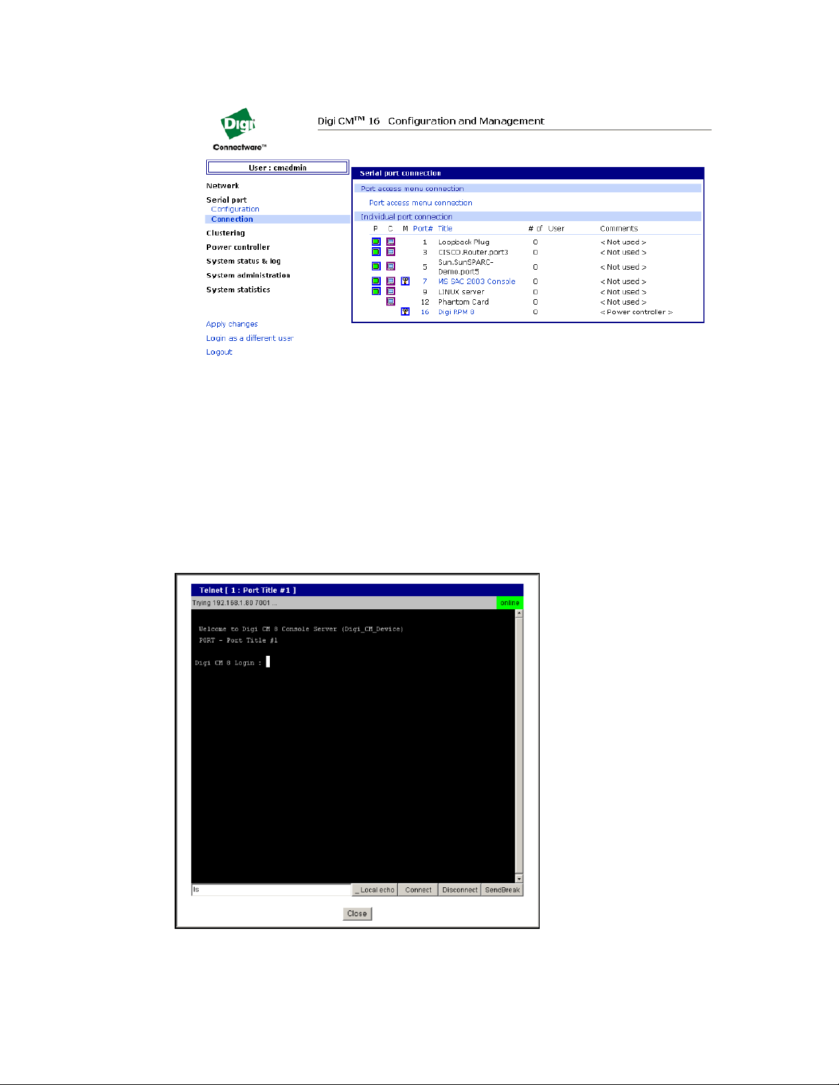
2 Click Serial port > Connection.
Digi CM User Guide 14
Page 15
Overview Web interface access menu
The P (Power) column allows you to control power of the attached devices, if a Remote Power
Management unit is attached and you have appropriate rights.
The M (Manage) column offers web based management for Windows Server 2003, Remote Power
Management units or Rackable Systems Management Card.
The “# of User” column shows how many users are actually connected to the port and the username
of the read/write user.
1 If you are conducting a special task through the console port, like BIOS upgrade and should not
be interrupted, you can notify other users by entering a comment upon connect. This comment
is shown here.Select a port by clicking the icon in the C (Console) column.
A Java applet or Telnet window opens with a login prompt.
Digi CM User Guide 15
Page 16

Overview Port Access Menu
Port Access Menu
The Port Access Menu provides access to ports. It is accessible to all users through the web interface,
Telnet and SSH sessions, and remote modem access.The information that follows shows you how to
access this menu.
Access type Permissions Procedure
Web interface Any user can use this method.
1 Access the web interface
2 Choose Serial port > Connection > Port access menu
connection
3 Log in
Telnet Any user can use this method.
1 Telnet to the Digi CM unit specifying its IP address and
port 7000. (7000 is the default socket port for both
Telnet and SSH) Example:
telnet 192.168.15.7 7000
2 Log in
Command line Root From the command line, issue the portaccessmenu
command. Example:
portaccessmenu
telnet http://digicm.digi.com
Here is a screenshot of the Port access menu.
Digi CM User Guide 16
Page 17

Overview Direct port access
Direct port access
Connect directly to a properly configured port through a Telnet or SSH session. Configuration
requirements include setting the Host Mode to Console Server Mode and the Protocol to either
Telnet or SSH. Ports, by default are set to Console Server Mode and Telnet. Use the following
information to make a Telnet or SSH connection to a port:
Type Command syntax Example: connection to port 3
Telnet telnet ip-address tcp-port
where ip-address is the Digi CM unit’s IP
address and tcp-port is the Listening TCP port
for a port
SSH ssh user-name@ ip-address tcp-port
where user-name is a user’s name,
ip-address is the Digi CM unit’s IP address and
tcp-port is the Listening TCP port for a port
Note The example assumes that the Listening TCP port is 7003, the default for port 3.
Custom menus
Custom menus are created by either root or the system administrator to limit your access to specific
ports. For more information, see Make custom menus.
telnet 192.168.15.7 7003
(7000 is the default socket port for both Telnet and
SSH)
ssh admin@ 192.168.15.7 -p 7003
(7000 is the default socket port for both Telnet and
SSH)
http://
digicm.digi.comconnect.asp?t=CISCO.Router.port3
Port escape menu
Port escape is the ability to escape from a port without disconnecting. Port escape is available in
main sessions as well as sniff sessions. Every connection method accommodates port escape. You
configure the escape sequence per port. Follow the procedure to configure the port escape
sequence.
1Serial Port > Configuration > Select the port number or All.
2 Host mode configuration > Port escape sequence - enter a letter for the Port escape sequence.
3 Click Save to flash and continue with other configurations or click Save & apply for the changes
to take effect.
Digi CM User Guide 17
Page 18

Overview Port escape menu
To open a sniff session:
1 Click Serial port > Connection.
2 Select the port you want to access.
3 Log in with your user name and password.
4 Enter the letter of the port escape sequence.
Digi CM User Guide 18
Page 19

Overview SNMP
Description of fields
The following table describes the fields and the operations for the port escape feature. You will only
see the fields allowed for your permissions.
Escape
Sequence
Ctrl+
m take over main session (read/write) only presented to users with read/ write access
s enter as a slave session (read only) only presented to users with read/ write access
b send break not functional for sniff users
l show last 100 lines of log buffer must enable logging for this option
d disconnect a sniff session only functional to admin
a send message to port user(s) not available to sniff users
r reboot device using power-switch only if power management is available on this
Description of action Occurrence
upon entering a session
upon entering a session
port
p power device on/off (show only on or off) only if power
x close current connection to port closes the
Note By entering the port escape sequence twice, it is directly transmitted (once) to the
connected device. If the escape sequence is entered twice within 1/2 second, the menu will
not open.
SNMP
An SNMP MIB to configure the Digi CM unit is available to be downloaded from digi.com/support.
Save and apply changes
In the web interface, you can save and apply configuration changes in two ways. With the one-step
method, you choose Save & apply and changes are saved and applied (take effect) immediately.
With the two-step method, you choose Save to flash, which immediately saves changes but the
changes do not take effect until you choose Apply changes. The following topics describe how to do
each of these operations.
One step: save and apply changes
management is available on this port
To save and apply changes immediately, choose the Save & apply button.
Digi CM User Guide 19
Page 20

Overview .Locater light
Two-step: save to flash and then apply changes
To save multiple changes but apply changes once, do the following:
Choose the Save to flash button.
When you finish changing the configuration, choose the Apply changes link, which is located on the
left navigation menu; or the Save & apply button at the bottom of the page.
For more details about Automatic Device Recognition, refer to
Port 3 shows a real world example of a detected device.
Automatic Device Recognition also monitors each of the configured serial ports. This allows you to
receive an e-mail or SNMP trap if there is a change in the expected response from the device
connected to the serial port. If the device goes down or is disconnected for any reason, you are
notified
.Locater light
The Digi CM 48-port unit has a locater light on the front panel labeled Find Me. All other Digi CM units
flash the serial port lights to indicate where the device is found.
If you access the web interface, log in to the Digi CM unit, and scroll down the page, you will find
additional links.
Click Start device locating and a popup box will appear to confirm. Click okay and the Digi CM unit
Find Me light will blink (other Digi CM models blink all LEDs).
To turn off the locater light, click Stop device locating.
Digi CM User Guide 20
Page 21

Getting started
Introduction . . . . . . . . . . . . . . . . . . . . . . . . . . . . . . . . . . . . . . . . . . . . . . . . . . . . . . . . . . . . . . . . . . . . . 22
Assigning IP settings from the console port . . . . . . . . . . . . . . . . . . . . . . . . . . . . . . . . . . . . . . . . . . . . 22
Configure for SSH . . . . . . . . . . . . . . . . . . . . . . . . . . . . . . . . . . . . . . . . . . . . . . . . . . . . . . . . . . . . . . . . . 23
Add, edit, and remove users . . . . . . . . . . . . . . . . . . . . . . . . . . . . . . . . . . . . . . . . . . . . . . . . . . . . . . . . . 25
Digi CM User Guide 21
Page 22

Getting started Introduction
Introduction
This section covers basic configuration topics. Included is information on assigning IP settings,
enabling secure access with the web interface, accessing the unit through SSH, and adding or
removing users.
Note Initial setup is described in the Quick Start Guide included with the product packaging. A
copy of this document is also available online here.
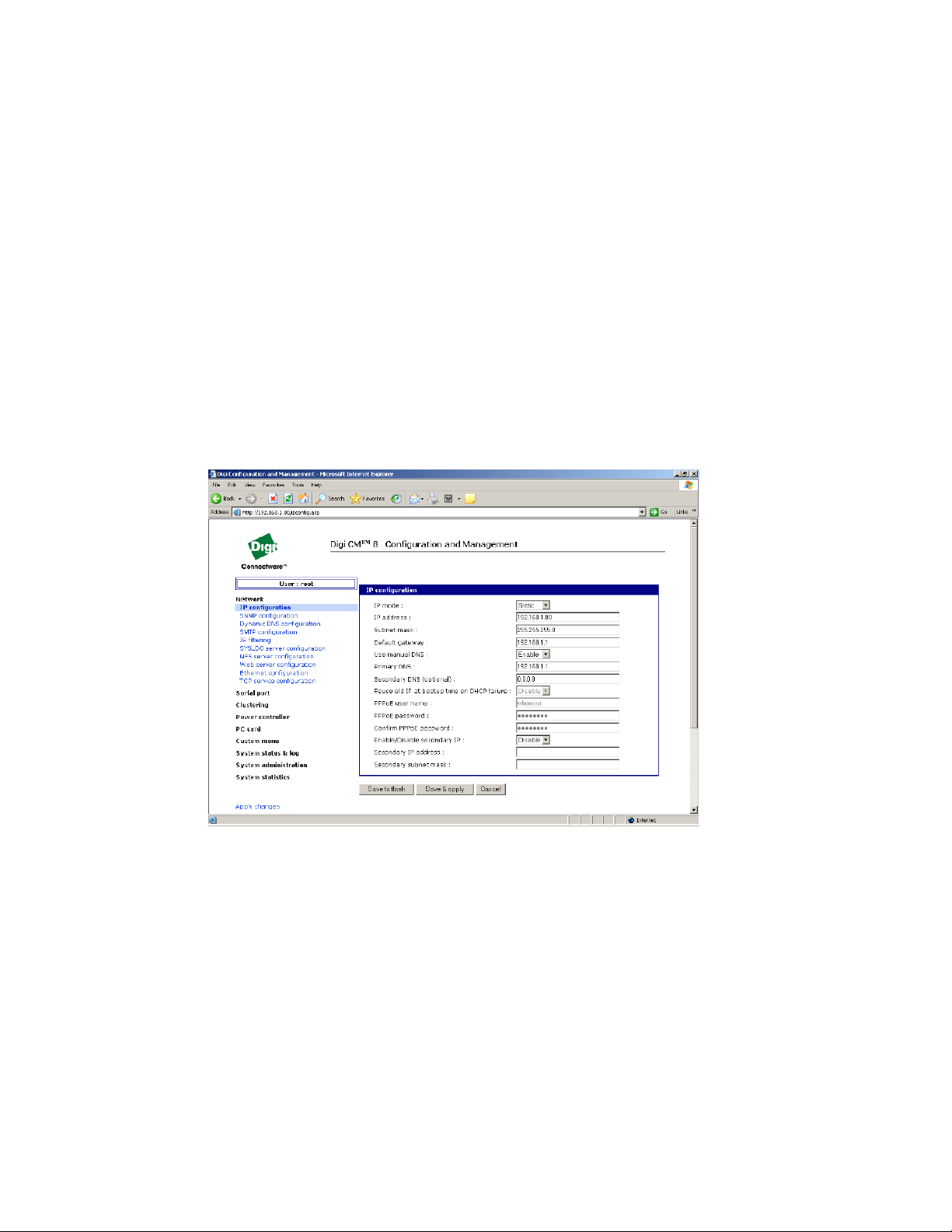
Assigning IP settings from the console port
The following steps use the console port to assign IP settings.
Note The default IP address is 192.168.161.5.
1 Connect the console port on the rear panel of the Digi CM unit to a serial port on a workstation
using the Ethernet console cable and the appropriate console adapter packaged with the the
Digi CM unit. The arrow in the following graphic points to the console port.
2 Configure a terminal emulation program, such as HyperTerminal, using the
following settings:
• bps = 9600
• data bits = 8
• parity = none
• stop bits = 1
• flow control = none
3 Establish a connection to the console port and press Enter to get a command prompt.
4 At the login prompt, log in as admin. The default password for admin is admin.
The Configuration menu appears.
5 Enter the number for Network Configuration.
6 Enter the number for IP configuration.
7 Enter the appropriate parameters for the IP settings.
8 Press ESC when done to return to the main configuration menu.
Digi CM User Guide 22
Page 23

Getting started Configure for SSH
Enter the number to exit and apply changes.Changes are saved and applied immediately. There
is no need to reboot.
Configure for SSH
Note The the Digi CM unit supports Blowfish and 3DES encryption methods for SSH.
Options
The Port Access Menu and individual ports can be configured for SSH.
Configure the Port Access Menu for SSH
1 Access the web interface.
2 Log in as root, admin, or a member of the port administration group. The default password for
root is dbps, and the default password for admin is admin.
3 Under Serial port > Configuration > Port access menu configuration.
The Port access configuration menu appears.
4 Select SSH as the Port access menu protocol.
Digi CM User Guide 23
Page 24

Getting started Configure for SSH
Note Log in on port access requires logging in twice (once for access to the port and once for port
access menu) when enabled. Disabled allows one log in directly to the port.
5 Click Save & apply.
Configure a Port for SSH
1 Access the web interface.
2 Log in as root, admin, or a member of the port administration group. The default password for
root is dbps, and the default password for admin is admin.
3 Under Serial port > Configuration.
4
5 Click Host mode configuration.
6 Specify SSH as the Protocol as shown in the following screenshot.
Digi CM User Guide 24
Page 25

Getting started Add, edit, and remove users
7 Click Save & apply.
Add, edit, and remove users
The root user and system administrator can add, remove, or edit users from the web interface.
Procedure
1 Access the web interface.
2 Log in as root or admin. The default password for root is dbps, and the default password for
admin is admin.
3 Under the System administration heading click Users administration.
Digi CM User Guide 25
Page 26

Getting started Add, edit, and remove users
4 Select Add, Edit, Remove.
• Add: Assign a user name, user group, password, and shell.
• Edit: Change user group, password, or their shell
• Remove: Remove a user from the system
5 Click Save & apply.
Note The root and admin users cannot be removed from the system.
For more information about configuring access rights for specific users see Configure user access
privileges.
About shell options
The shell program selection determines the interface you see when establishing a Telnet or SSH
session with the Digi CM unit.
User Group Shell Program Options
root command line
system admin command line, configuration menu, port access menu, custom menus
port admin configuration menu, port access menu, custom menus
user port access menu, custom menus
Digi CM User Guide 26
Page 27

Install and configure PC cards
Introduction . . . . . . . . . . . . . . . . . . . . . . . . . . . . . . . . . . . . . . . . . . . . . . . . . . . . . . . . . . . . . . . . . . . . . 28
Compatible PC cards . . . . . . . . . . . . . . . . . . . . . . . . . . . . . . . . . . . . . . . . . . . . . . . . . . . . . . . . . . . . . . 28
Add a compact-flash card . . . . . . . . . . . . . . . . . . . . . . . . . . . . . . . . . . . . . . . . . . . . . . . . . . . . . . . . . . . 28
Add a network card . . . . . . . . . . . . . . . . . . . . . . . . . . . . . . . . . . . . . . . . . . . . . . . . . . . . . . . . . . . . . . . . 29
Add a wireless LAN card . . . . . . . . . . . . . . . . . . . . . . . . . . . . . . . . . . . . . . . . . . . . . . . . . . . . . . . . . . . . 30
Add a serial modem . . . . . . . . . . . . . . . . . . . . . . . . . . . . . . . . . . . . . . . . . . . . . . . . . . . . . . . . . . . . . . . 31
Digi CM User Guide 27
Page 28

Install and configure PC cards Introduction
Introduction
This section includes information on adding and configuring PC cards for the Digi CM unit. PC card
devices that can be added to the the Digi CM unit include a serial modem, compact-flash card,
wireless LAN card, and a network LAN card.
Compatible PC cards
All compact-flash cards work with the Digi CM unit, but not all serial modem, wireless LAN, or regular
LAN cards do. To see a list of compatible cards that have been tested with the Digi CM unit, visit the
Digi support site at digi.com/products/consoleservers/digicm#productsupport.
Add a compact-flash card
A PC card slot is located on the front panel of the Digi CM unit. The arrow in the following graphic
indicates the PC card slot.
To install and configure the compact-flash card on the Digi CM unit, do the following.
1 Insert the card into the PC card slot.
2 Access the web interface.
3 Under the PC card heading click Configuration.
Note Always select the Stop card service button and Save & apply before removing the PC card.
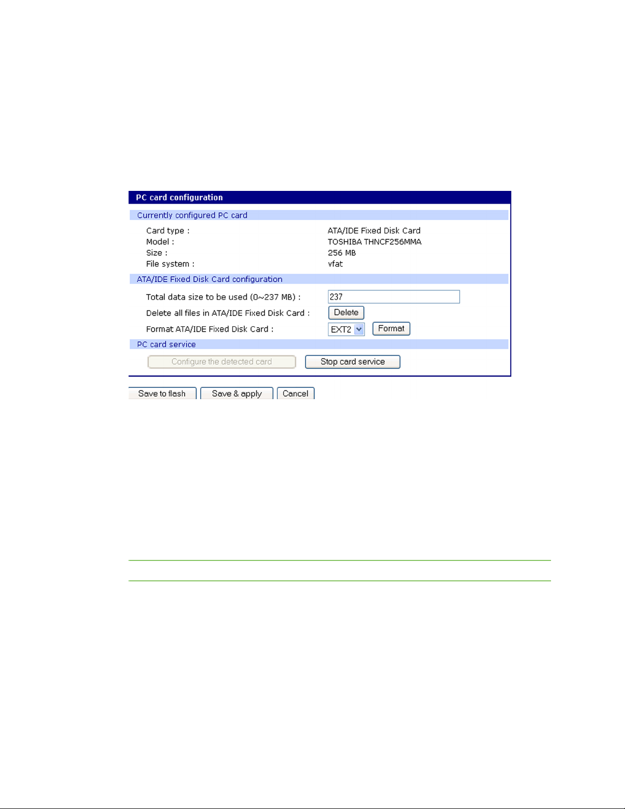
4 Click Configure the detected card.
The following fields appear on the configuration page:
Digi CM User Guide 28
Page 29
Install and configure PC cards Add a network card
ATA/IDE Fixed Disk Card configuration
Total data size to be used - Enter the amount of memory you want to assign to the compact-
flash card for configuration files.
Delete all files in ATA/IDE Fixed Disk Card - Select the Delete button to clear the compact-flash
card of all files.
Format ATA/IDE Fixed Disk Card - The options are EXT2 or FAT formats. Select the format
option and then select the Format button.
5 Enter the appropriate parameters on the configuration page.
6 Click Save to flash or Save & apply.
Add a network card
To install and configure a network card on the Digi CM unit, do the following.
1 Insert the card into the PC slot.
2 Access the web interface.
3 Under the PC card heading, click Configuration.
Note The card is automatically discovered and a configuration menu is displayed.
4 Enter the appropriate parameters in the configuration menu.
Digi CM User Guide 29
Page 30

Install and configure PC cards Add a wireless LAN card
5 Click Save & apply.
Note If DHCP is active the IP address will appear after the configuration is saved and applied.
Add a wireless LAN card
To install and configure a wireless LAN card on the Digi CM unit, do the following.
1 Insert the card into the PC slot.
2 Access the web interface.
3 Under the PC card heading, click Configuration.
Note The card is automatically discovered and a configuration menu is displayed.
4 Click Configure the detected card.
5 Enter the appropriate parameters in the configuration menu.
WEP is the acronym for Wired Equivalent Privacy and is a security protocol for wireless LANs
using encryption to protect data transfers. If you are unsure of the settings for the wireless card,
see your network administrator.
SSID - Set Service Identifier and is the name of the wireless LAN network
Use WEP key - Enable or disable the WEP key
Digi CM User Guide 30
Page 31

Install and configure PC cards Add a serial modem
WEP mode - Encrypted or unencrypted
WEP key length - The options are 40 or 128 bits if the WEP key is enabled
WEP key string - Refer to the wireless network administrator for the wireless encryption key
string
6 Click Save to flash.
Add a serial modem
The modem must first be inserted and installed on your system before it can be used. To configure
the modem do the following:
1 Access the web interface.
2 From the menu click Configuration under the PC card heading.
Note The card is automatically discovered and a configuration menu is displayed.
Digi CM User Guide 31
Page 32

Install and configure PC cards Add a serial modem
3 Click Configure the detected card.
4 Edit any appropriate parameters and Click Save & apply.
Digi CM User Guide 32
Page 33

System status and port logging
Introduction . . . . . . . . . . . . . . . . . . . . . . . . . . . . . . . . . . . . . . . . . . . . . . . . . . . . . . . . . . . . . . . . . . . . . 34
System status & log . . . . . . . . . . . . . . . . . . . . . . . . . . . . . . . . . . . . . . . . . . . . . . . . . . . . . . . . . . . . . . . . 34
Enable the log storage location . . . . . . . . . . . . . . . . . . . . . . . . . . . . . . . . . . . . . . . . . . . . . . . . . . . . . . 35
Configure system logging . . . . . . . . . . . . . . . . . . . . . . . . . . . . . . . . . . . . . . . . . . . . . . . . . . . . . . . . . . . 39
Configure port logging . . . . . . . . . . . . . . . . . . . . . . . . . . . . . . . . . . . . . . . . . . . . . . . . . . . . . . . . . . . . . 40
Digi CM User Guide 33
Page 34

System status and port logging Introduction
Introduction
The Digi CM unit provides four options for saving system and port logs:
▪ A syslog server
▪ An NFS server
▪ A compact-flash card
▪ The Digi CM unit ’s memory
When memory is selected as the storage location, log files are saved to volatile memory, meaning
files are lost when the power is turned off. To use a syslog server, an NFS server, or a compact-flash
card, you must first enable the devices and enter the required information. Compact-flash cards
must be installed before they can be enabled and configured for logging purposes.
System logs track events such as logins, authentication failures, system configuration changes, and
more. Port logs, on the other hand, document the data flow through the serial ports. This chapter
outlines locations for viewing the system and port logs.
System status & log
For basic system information click System status & log. The parameters for the system status are
described in the following list.
System Information
Model No. - Identification of Digi device
Serial No. - Serial number of product
F/W Rev. - Revision number of firmware
B/L Ver. - Bootloader version
MAC address - MAC address of Digi device
Uptime - Amount of time since last reboot
Current time - Time based on time set for Digi device
System logging - Status of system logging either Enabled or Disabled
Send system log by email - Condition for notification:
PC card type - Description of PC card if configured
PC card model - Model of PC card if configured
Power status - Dual power ( 1 - Normal , 2 - Normal )
IP Information
IP mode - Method for setting IP address either Static, DHCP, PPPoE, or Disable
IP expiration - When the IP address will expire
IP address - Actual IP address
Subnet mask - Address of the Subnet mask
Gateway - Address of the Gateway
Receive/Transmit errors - Number of errors from receiving or transmitting
Primary DNS - IP address of the primary DNS
Secondary DNS - IP address of the secondary DNS
Digi CM User Guide 34
Page 35

System status and port logging Enable the log storage location
Enable the log storage location
Enable an NFS server
You can save log data to an NFS server, but the NFS server must be configured with read and write
privileges. To use an NFS server, you must specify the NFS server’s IP address and its mounting path.
Encrypted NFS is using a SSH connection to tunnel all data. To enable the NFS server for port or
system logging, do the following:
1 Access the web interface.
2 Under the Network heading, Click NFS server configuration.
NFS service - Enabled or disabled.
Primary NFS server name - IP address of NFS server or
Mounting path on primary NFS server - Directory to primary NFS server
Primary NFS timeout - Interval in seconds before timeout (5-3600)
Primary NFS mount retrying interval - Interval in second between attempts to connect (5-
3600)
Enable/Disable encrypted primary NFS server - If server supports encrypted NFS server
Encrypted primary NFS server user - User name of server
Encryped primary NFS server password - Password
Secondary NFS service - Enabled or Disabled
Secondary NFS server name - Name of server
Mounting path on secondary NFS server - Directory to server
Secondary NFS timeout (sec, 5-3600) - Timeout in seconds
Secondary NFS mount retrying interval (sec, 5-3600) - Retry interval in seconds
Enable/Disable encrypted secondary NFS server - If secondary server supports encrypted NFS
server
Encrypted secondary NFS server user - User name
Encrypted secondary NFS server password - Password
Confirm secondary NFS server password - Repeat password
Digi CM User Guide 35
Page 36

System status and port logging Enable the log storage location
3 Choose Enabled.
4 Enter the IP address of the primary and secondary (if applicable) NFS server and the mounting
path of each.
5 Click Save & apply.
Alert for NFS server disconnect
You can also set up an email alert and/or an SNMP trap configuration for an NFS server disconnect.
To configure this feature, use this procedure.
1 Farther down the NFS Configuration screen, at the Email alert configuration, select Enable.
2 Enter the Title of email and the Recipient's email address.
3 For an SNMP trap configuration select Enable NFS disconnection trap.
4 Select Enable for Use global SNMP configuration, and enter the IP information for Trap receiver
settings.
5 Click Save & apply.
Digi CM User Guide 36
Page 37
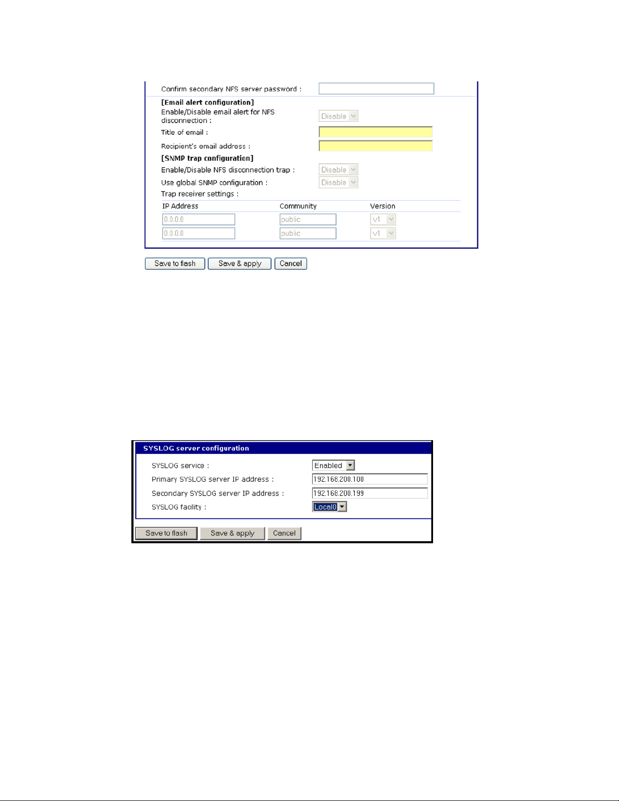
System status and port logging Enable the log storage location
Enable SYSLOG server
To enable the Digi CM unit for system or port logging on a syslog server:
1 Access the web interface.
2 Under the Network heading, click SYSLOG server configuration.
3 Choose Enable.
4 Enter the IP address of the primary and secondary (if applicable) syslog server, and select the
syslog facility from the drop down menu.
5 Click Save & apply.
Enable a compact-flash card
The compact-flash card must be installed and configured on the Digi CM unit before it can be used
for system logging or storing the Digi CM unit’s configuration information. When storing log files to
an external flash card, the size of the available storage is dependent on both the size of the card and
the port counts of the Digi CM unit used. The maximum settings for log file sizes are listed in the
following table. See also Add a compact-flash card.
Digi CM User Guide 37
Page 38

System status and port logging Enable the log storage location
Tot a l f l a s h card size Digi CM System log Port log (per port) Total memory used
32 8 4.6 3.1M 29M
16 4.6 1.53M
32 4.6 762K
48 4.6 500K
64 8 9.2 6.2M 58M
16 9.2 3.1M
32 9.2 1.53M
48 9.2 1.02M
128 8 18.4 12.3M 118M
16 18.4 6.2M
32 18.4 3.1M
48 18.4 2.0M
256 8 36.8 24.6M 236M
16 36.8 12.3M
32 36.8 6.2M
48 36.8 4.1M
Enable the Digi CM unit’s memory
The Digi CM unit ’s memory is already enabled for port logging and needs to be configured only for
system logs or port logs. When storing log files to the Digi CM unit’s local memory, a total of 3.5M is
available. The amount of memory per serial port is dependent on the port count of the Digi CM unit
used. The log file sizes shown in the following table are maximum settings. See also Configure
system logging.
Digi CM System log Port log (per port) Total memory used
8 300K 400K 3.5M
16 200K
32 100K
48 66K
Digi CM User Guide 38
Page 39

System status and port logging Configure system logging
Configure system logging
To configure the Digi CM unit for system logging, do the following:
1 Access the web interface.
2 Under System status & log, click System logging.
3 Choose Enabled for System logging and the log buffer size.
4 From the System log storage location, choose the location from the drop down menu. The
choices are dependent on what you have enabled and/or installed. The Digi CM unit ’s memory
choice is always available.
System logging - Enable or Disable
System log storage location - Memory or NFS server
System log to SYSLOG server - Enable to store system logs to a SYSLOG server
System log buffer size (KB, 300 max) - Log buffer size in KB
Automatic backup on mounting - This parameter defines the action taken if a NFS partition of a
CF card or NFS server is mounted or re-mounted.
• Enable: rename the existing log file by adding a -xx with xx being a incremented number.
• Disable: keep writing to the existing log file.
Send system log by Email
Number of log messages to send in an email (1-100) - Number of messages
System log recipient’s mail address - Email address for log recipient
Digi CM User Guide 39
Page 40

System status and port logging Configure port logging
5 Choose to enable or disable email alerts and the number of log messages to send. The default
value is 5 seconds for the delay in log email messages.
6 Enter the contact email address.
7 Click Save & apply.
View system logs
The system logs can be viewed from the web interface on the System logging page or from the
location where they have been saved. The following table lists the file locations of the system logs.
System Logfile
Log storage File location
Digi memory /tmp/logs
Compact-flash card /mnt/flash/logs
Syslog server must be viewed on the syslog server
NFS server /mnt/nfs/logs
Configure port logging
If a serial port is configured for console server mode, the port logging feature can be enabled. Port
logging allows you to save serial data to the memory of the Digi CM unit, a compact-flash card, a
syslog server, or to an NFS server. If the memory is used for port logging, all data is cleared when the
system’s power is turned off.
You can also define alarm keywords for each serial port and send email alerts or SNMP traps to
enable unattended serial data monitoring. The following steps configure a serial port for port
logging in console server mode.
1 Access the web interface.
2 Under the Serial port heading, click Configuration.
3 Choose All or the Individual port, and then Port logging.
4 Configure the settings:
Logging direction - Specify what to log:
• Server – only server output,
• User – only user output,
• Both with/without arrows – server and user output with/without directional arrows.
• Default: server output.
Security advice: When logging user output passwords will be saved into the log file!
Port log to SYSLOG server - Enable to store port logs to a SYSLOG server
Port logging filename - Options are to specify your own or use the port title for the port log
filename
Digi CM User Guide 40
Page 41

System status and port logging Configure port logging
Show last 10 lines of a log upon connect -Show previous last 10 lines of log when connecting to
this port
Strip the ^M from SYSLOG -For logging to a SYSLOG server, strip out all ^M
Automatic backup on mounting - This parameter defines the action taken if a NFS partition of a
CF card is mounted or re-mounted.
• Enable: rename the existing log file by adding a -xx with xx being an incremented number.
• Disable: keep writing to the existing log file.
Monitoring interval -The frequency in seconds to update the port log
5 Click Save & apply.
Note When port logging is enabled, a Port Event Handling page is available to create alarm
keywords and send alerts. See Alerts and notifications for more information.
Digi CM User Guide 41
Page 42

System status and port logging Configure port logging
View port logs
The port logs can be viewed from the web interface on the Port logging page or from the location
where they have been saved. The following table lists the file locations of the system logs.
Port logfile
Log storage File location
Digi memory /tmp/port#data
Compact-flash card /mnt/flash/port#data
Syslog server must be viewed from the syslog server
NFS server /mnt/nfs/port#data
To view the port logs on the NFS server for port number 5, enter the following command:
more /mnt/nfs/port5data
Partial logfiles can also be viewed on the web interface by going to Serial port > Configuration >
select a port # you want to view > Port logging.
Digi CM User Guide 42
Page 43

Configure ports
Introduction . . . . . . . . . . . . . . . . . . . . . . . . . . . . . . . . . . . . . . . . . . . . . . . . . . . . . . . . . . . . . . . . . . . . . 44
Enable and disable the ports . . . . . . . . . . . . . . . . . . . . . . . . . . . . . . . . . . . . . . . . . . . . . . . . . . . . . . . . 44
RealPort support . . . . . . . . . . . . . . . . . . . . . . . . . . . . . . . . . . . . . . . . . . . . . . . . . . . . . . . . . . . . . . . . . . 44
Resetting ports . . . . . . . . . . . . . . . . . . . . . . . . . . . . . . . . . . . . . . . . . . . . . . . . . . . . . . . . . . . . . . . . . . . 45
Port title . . . . . . . . . . . . . . . . . . . . . . . . . . . . . . . . . . . . . . . . . . . . . . . . . . . . . . . . . . . . . . . . . . . . . . . . . 45
Configure Automatic Device Recognition . . . . . . . . . . . . . . . . . . . . . . . . . . . . . . . . . . . . . . . . . . . . . . 46
Apply all ports settings . . . . . . . . . . . . . . . . . . . . . . . . . . . . . . . . . . . . . . . . . . . . . . . . . . . . . . . . . . . . . 47
Host mode configuration . . . . . . . . . . . . . . . . . . . . . . . . . . . . . . . . . . . . . . . . . . . . . . . . . . . . . . . . . . . 48
Configure host mode . . . . . . . . . . . . . . . . . . . . . . . . . . . . . . . . . . . . . . . . . . . . . . . . . . . . . . . . . . . . . . 51
Supported protocols . . . . . . . . . . . . . . . . . . . . . . . . . . . . . . . . . . . . . . . . . . . . . . . . . . . . . . . . . . . . . . . 52
Serial port parameters . . . . . . . . . . . . . . . . . . . . . . . . . . . . . . . . . . . . . . . . . . . . . . . . . . . . . . . . . . . . . 52
DTR behavior . . . . . . . . . . . . . . . . . . . . . . . . . . . . . . . . . . . . . . . . . . . . . . . . . . . . . . . . . . . . . . . . . . . . . 53
Specialty Use of Port -When Data is Processed in Chunks . . . . . . . . . . . . . . . . . . . . . . . . . . . . . . . . . 53
Remote ports . . . . . . . . . . . . . . . . . . . . . . . . . . . . . . . . . . . . . . . . . . . . . . . . . . . . . . . . . . . . . . . . . . . . . 54
Digi CM User Guide 43
Page 44

Configure ports Introduction
Introduction
This section provides information on configuring serial ports. Key port configuration attributes
include whether or not the port is enabled or disabled, the host mode, which defines a type of
communication between the port and a remote host, the protocol, authentication, user access
restrictions, and serial communication attributes. It also covers remote port support.
Enable and disable the ports
All serial ports may be enabled or disabled individually or as a group from the web interface.
1 Click Serial port > Configuration > Port number or all
2 Select Enable or Disable from the drop down menu.
3 Click Save to flash and continue with other configurations or click Save & apply.
RealPort support
RealPort software provides a virtual connection to serial devices, no matter where they reside on
the network. The software is installed directly on the host and allows applications to talk to devices
across a network as though the devices were directly attached to the host. In actuality, the devices
are connected to a Digi device server or terminal server somewhere on the network.
RealPort is unique among COM port re-directors because it is the only implementation that allows
multiple connections to multiple ports over a single TCP/IP connection. Other implementations
require a separate TCP/IP connection for each serial port. Unique features also include full hardware
and software flow control, as well as tunable latency and throughput.
When you use RealPort (configured on a per port basis) the Digi CM unit functionality is unavailable.
That is to say that the Digi CM unit can be used for console management or for RealPort COM redirection but not both. An example of RealPort use would be remote kernal debugging of Microsoft
Windows Servers. To enable RealPort use the following procedure.
Note RealPort does not support authentication and user rights are not validated.
1 To enable RealPort click Serial port > Configuration > Port number.
Digi CM User Guide 44
Page 45
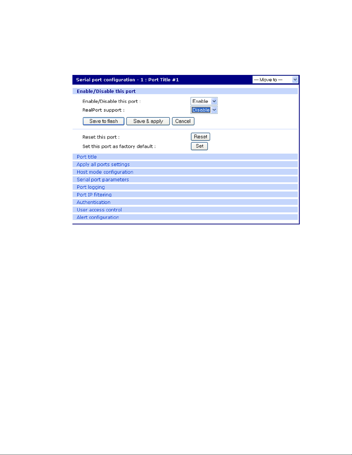
Configure ports Resetting ports
2 Select Enable this port from the drop down menu.
3 Select Enable RealPort support from the drop down menu.
4 Click Save to flash and continue with other configurations or click Save & apply.
Resetting ports
The Digi CM unit allows you to restart all processes associated with a port and to disconnect all
sessions.
To reset an individual port:
1 Click Serial port > Configuration > Port number.
2 Click Reset this port: Reset.
Reset individual port settings
Individual ports can be reverted to factory defaults.
1 Click Serial port > Configuration > Port number.
2 Click Set this port as factory default: Set.
Port title
The Digi CM unit offers multiple ways to configure the port title; both manually and automatically.
The default is set to “Port Title # xx” with xx being the port-number.
Automatic Device Recognition allows the Digi CM unit to evaluate the attached devices and
populate the port title. Additionally the Digi CM unit can generate a SNMP trap or send an email in
case the response of the device changes or it stops responding.
Digi CM User Guide 45
Page 46
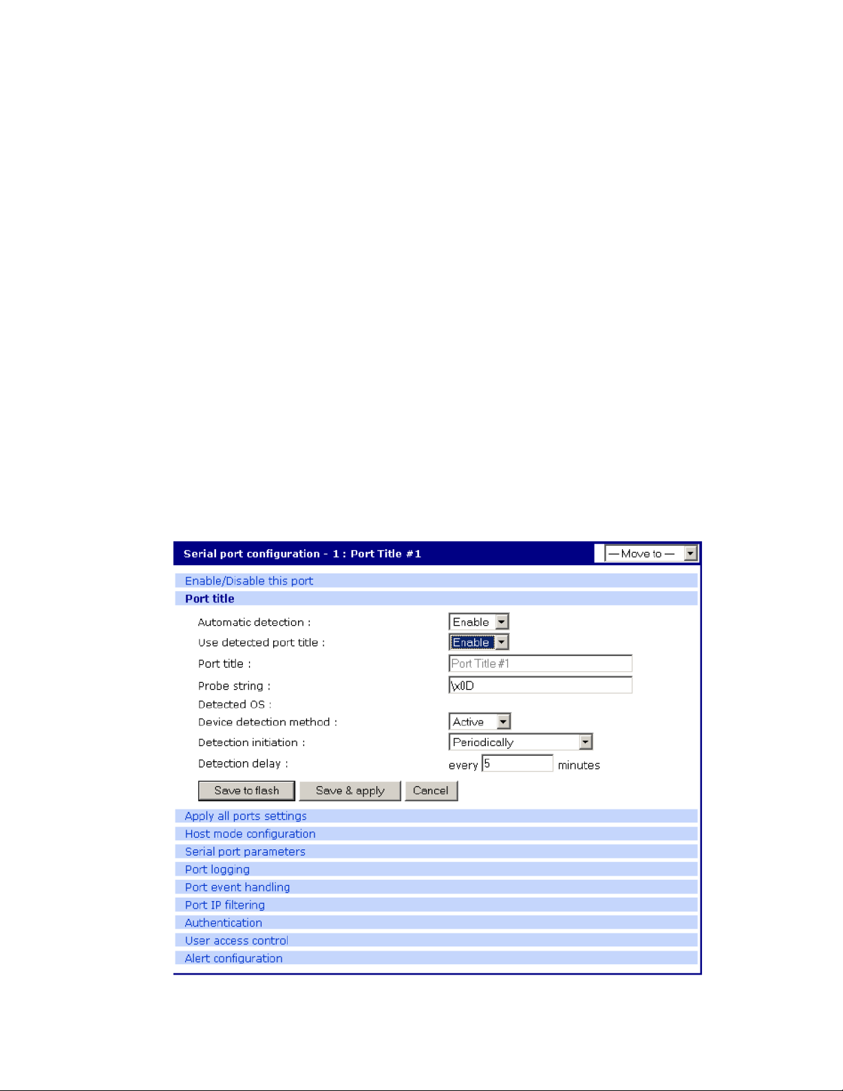
Configure ports Configure Automatic Device Recognition
If Active detect is selected, a configurable probe string (carriage return =0x0d by default) is sent to
the console port and the response is saved to a file at /var/run/systemrep_raw.portxx with xx being
the port number.
This file is parsed using a script /tmp/cnf/active_detect and the operating system and device name
are written to files: /var/run/HostnamePortxx and /var/run/OSPortxx.
The commands to parse the system response are user customizable, so if a device is not recognized
immediately by the Digi CM unit, add a rule to the file.
If Passive detect is selected, no probe string is sent to the attached device but the port buffer is
analyzed.
The script /tmp/cnf/passive_detect is executed and the results are saved to files: /var/run/
HostnamePortxx and /var/run/OSPortxx.
After editing the scripts as either active_detect or passive_detect, save them to flash using the
saveconf command so they are not lost after a reboot.
Configure Automatic Device Recognition
Configure a serial port for Automatic Device Recognition.
1 Access the web interface.
2 Under the Serial Port heading, Click Configuration.
3 Choose All or an Individual port > Serial port parameters.
4 Edit the fields as they apply to your configuration.
Digi CM User Guide 46
Page 47

Configure ports Apply all ports settings
Automatic detection - Enable or disable automatic detection of devices
Use detected port title - Enable if you want the Digi CM unit to automatically use the results of
the detection mechanism to populate the port title. Disable if you want the default port title. If
you choose Disable, you can still use the alarm feature.
Port title - Manually entered or automatically populated title of the port.
The Digi CM unit allows access to a port by using only the number of the port title, making it
unnecessary to know the serial port number.
The default is set to “Port Title xx” with xx being the port number.
Probe string - The probe string is an ASCII string that is sent to the device.
Special characters are coded in hexadecimal values like:
CR \x0d
LF \x0a
ESC \x1B
Examples are:
Parse string output
root\x0d\x0a root<CR><LF>
\x1Btest\x0d <ESC>test<CR>
\x1B test\x0d <ESC><Space>test<CR>
\x1b\x20test\x0D <ESC><Space>test<CR>
\x1B\x20\x74\x65\x73\x74\x0d <ESC><Space>test<CR>
Detected OS - Displays the result of the Active or Passive detection process.
Device detection method - If Active is selected a probe string is periodically sent to the device
and the response is analyzed. If Passive is selected, the port logging is parsed to determine the
device name and the OS.
Detection initiation - Active only if automatic detection is Enabled. Periodically or If new device
is detected are the choices in the drop down menu. If Periodically is selected, the probe string is
sent once every n minutes to the device while no connection is active to the serial port. When a
new device is detected is selected, the probe string is only sent if a change on the DSR signal on
the serial port is detected. Normally a device will activate the DSR signal if the serial port
becomes active.
Detection delay - The delay before the first active detect process is started and between active
detections.
5 Click Save & apply.
Apply all ports settings
The Digi CM unit supports managing all ports simultaneously. If changes are made to the page “all
ports”, they are automatically applied to all ports. You can choose to exclude ports from this
feature.
To enable/disable this feature for a port:
1 Access the web interface.
2 Under the Serial Port heading, click Configuration.
Digi CM User Guide 47
Page 48

Configure ports Host mode configuration
3 Choose an individual port > Apply Port Settings.
4 Select Enable or Disable from the drop down menu.
5 Click Save to flash and continue with other configurations or click Save & apply.
Note When changing a parameter for all ports, all settings of the complete page are applied to all
ports.
Host mode configuration
The Digi CM unit provides four modes of communication between serial devices and remote hosts.
Console server, terminal server, dial-in modem, and dial-in terminal server. These are described in
the following sections.
Console server mode
Configuring a serial port as a console server creates a TCP socket on the Digi CM unit that listens for
a Telnet or SSH client connection. When you connect to the TCP socket, you have access to the
device attached to the serial port as though the device were connected directly to the network.
RawTCP is also supported with the Console Server Mode.
Digi CM User Guide 48
Page 49

Configure ports Host mode configuration
serial
Connection request
terminals
serial
Connection request
Terminal se rve r mode
In terminal server mode, the Digi CM unit’s serial port is configured to wait for data from the device
connected to the port. If data is detected, the Digi CM unit starts a TCP session as a Telnet or SSH
client to a pre-defined server. The server must be defined by you before the port can be configured
for a Telnet or SSH client. This mode is used when you want to access servers on the network from a
serial terminal. RawTCP is also supported with the Terminal Server Mode.
Dial-In modem mode
In this mode, the Digi CM unit assumes an external modem is attached to the serial port and is
waiting for a dial-in connection from a remote site. When a user dials-in using a terminal
application, the Digi CM unit accepts the connection and displays the appropriate prompt or menu
for you that logged in. Example: User ’root’ would see the command line interface (CLI), whereas the
user ’admin’ would see the config menu or CLI depending on the shell for that user.
Digi CM User Guide 49
Page 50

Configure ports Host mode configuration
Dial-In terminal server
Dial-in terminal server mode is a combination of the terminal server mode and the dial-in modem
mode. In the dial-in terminal server mode, the Digi CM unit assumes the serial port is connected to
an external modem and is waiting for a dial-in connection from a remote site. When you dial-in using
terminal applications, the Digi CM unit accepts the connection as a Telnet or SSH client to a predefined server. This mode is most frequently used when you want to use modems to access servers
on a network.
Digi CM User Guide 50
Page 51

Configure ports Configure host mode
Configure host mode
To configure a serial port for host mode, enter the values in the applicable fields. To access the Host
mode configuration screen, do the following:
1 Access the web interface.
2 Under the Serial Port heading, click Configuration.
3 Choose All or an Individual port > Host mode configuration.
4 Fill in the highlighted fields as they apply to your configuration.
Host mode - The options are console server mode, terminal server mode, dial-in modem mode,
and dial-in terminal server mode.
Type of console server - The options are MS SAC - English and MS SAC - International which you
use to provide a graphic user interface to the Windows Server 2003 Special Administration
Console (see Microsoft SAC support) and Other, which you use in all other cases.
Rackable Systems Mgmt Card - Enable to use Rackable Management card.
Enable/Disable assigned IP - Determines whether an IP address will be assigned to the port.
The default is Disabled.
Assigned IP - Also known as alternate IP, this field assigns an IP address to the port, enabling you
to Telnet directly to the serial port using an IP address (without having to specify a TCP port).
Listening TCP port - This is the TCP port you will specify when connecting directly to the port
using Telnet or SSH.
Protocol - The options are SSH, RawTCP, and Telnet.
Digi CM User Guide 51
Page 52

Configure ports Supported protocols
Inactivity timeout - In seconds, the time set for inactivity to trigger an action. Setting the timeout
to 0 (zero) means no timeout.
Enable/Disable port escape sequence - Allows the port escape sequence to function.
Port escape sequence - The key combination to initiate port escape.
Port break sequence - The sequence of characters that sends a break character to a device.
Use comment - Determines whether a port user is prompted to add a comment each time the
port is accessed.
Quick connect via - Determines method for connecting to a port when in console server mode.
Available with Telnet.
Web applet encoding - Supported languages for Java terminal.
5 Click Save & apply.
Supported protocols
In configuring a serial port, you have three protocol options. The three protocols available are:
RawTCP, SSH, and Telnet. Choose SSH as the protocol when logging in from an SSH client program
to access a port. Choose RawTCP when connecting directly to a TCP socket. Choose Telnet when
logging in from a Telnet client program and accessing the ports. Use the Host mode configuration
page in the web interface to select the correct protocol.
Serial port parameters
In attaching a serial device to the Digi CM unit’s serial port, the port parameters must match. The
serial ports by default are enabled, meaning you have full access to the port. To configure the port
parameters for the Digi CM unit, do the following:
1 Access the web interface.
2 Under the Serial Port heading, Click Configuration.
3 Choose All or an Individual port > Serial port parameters.
4 Fill in the serial port parameters. The following are the defaults: bps=9600, data bits=8,
parity=none, stop bits=1, flow control=none, and DTR behavior=High when open.
5 Click Save & apply.
Digi CM User Guide 52
Page 53

Configure ports DTR behavior
DTR behavior
DTR can be set on the serial port to one of three settings: always high, always low, or High when
open. Setting the DTR to High when open keeps the DTR high if a TCP connection is established. The
DTR setting cannot be set by you when the host mode is configured for dial-in modem or dial-in
terminal server mode.
Inter-character timeout
This setting is only available when the host mode protocol is set for RawTCP. The parameter sets the
time value for the Digi CM unit to transfer data stored in the buffer. The Digi CM unit transfers data
when the buffer is full using the TCP/IP protocol. However, if it is not full, the Digi CM unit will also
transfer data dependent on the timeout value selected.
Specialty Use of Port -When Data is Processed in Chunks
Some applications are written to process only chunks of data rather than continuous streams of
data. The Digi CM unit supports “chunking” holding back data from the serial device to the
application on the network until it detects a delimiter - at which point it sends the data to the
application.
To configure a port for this mode:
1 Open a web connection to the Digi CM unit.
2 Click Serial Port > Configuration.
3 Select All ports to configure.
4 Click Host Mode configuration.
5 Select Serial port parameters
6 Configure the delimiter and supporting settings. Descriptions of the options follow.
Enable/Disable delimiter - Allows delimiter to function.
Digi CM User Guide 53
Page 54

Configure ports Remote ports
Delimiter - Define the sequence that should be received before forwarding the data to the
application
Delimiter option - with delimiters - sends the delimiter as part of the data to the application
without delimiters - remove the delimiter before sending the data to the application
Inter character time-out timeout - In msec (1-10000) If no delimiter is detected the data is
delivered after this timeout has elapsed.
Remote ports
The Digi CM unit supports remote ports. Remote ports are any type of port that can be accessed
using Telnet or SSH protocol. Types of ports include ports that are provided using PortServer
Terminals Servers or Sun ILOM ports. This feature establishes the Digi CM unit as the central access
system for any kind of text based out-of-band management. Using the Digi CM unit as a central
access system has multiple advantages:
▪ Central point of access
▪ Central user authentication
▪ Capturing of every user transaction on the remote system
▪ Keyword monitoring and alarm while connection is up
Configure remote ports
To configure a remote port use the following procedure.
1 Access the Digi CM unit’s web interface.
2 Under the Serial Port heading click Configuration.
3 Scroll down the page to the section called Remote port configuration.
4 Enter the port title and click Add.
5 A pop-up window will appear to confirm the action.
6 Click the port title to access the configuration menus.
7 Select Remote port parameters.
8 Enter the IP address, port number, and protocol to use.
9 Confirm you selections by clicking Save & apply. A pop-up window will appear to confirm the
successful execution.
Note If you want to use a Digi PortServer TS 2 as remote device you would configure: IP address as
assigned, IP port 2001 for port 1 or 2002 for port 2 and telnet or 2501/ 2502 when using SSH
as protocol.
All other settings of the remote port are equivalent to the settings of a local serial port.
Access a remote port
You can connect to a remote port using the web, Telnet or SSH client. You can also use the port
access menu or a custom menu to simplify navigation
Web Access
Digi CM User Guide 54
Page 55

Configure ports Remote ports
Click Serial ports > Connection > Port number.
Remote ports are sorted below the physical serial ports as V1...
Te ln et
Telnet to the IP and the port number (the specific port number is defined on the ’Host mode
configuration’ page.
telnet 143.191.3.9 7051
SSH to the port number
SSH to the IP and the port number (the specific port number is defined on the ’Host mode
configuration’ page).
SSH to the port name
SSH to the IP and the port number (the specific port number is defined on the ’Host mode
configuration’ page).
Ssh user-name:’t=port-title’@ip-Address
Ssh sunadmin:’t=Switch3level’:@MainDigi
You can access a remote port just like any local port:
- directly using the portnumber
The parameters of the remote port are equivalent to regular serial ports. Enter any additional
parameters for the remote and click Save & apply or Apply all changes.
Digi CM User Guide 55
Page 56

Alerts and notifications
Introduction . . . . . . . . . . . . . . . . . . . . . . . . . . . . . . . . . . . . . . . . . . . . . . . . . . . . . . . . . . . . . . . . . . . . . 57
Configuring SMTP alerts . . . . . . . . . . . . . . . . . . . . . . . . . . . . . . . . . . . . . . . . . . . . . . . . . . . . . . . . . . . . 57
SNMP information . . . . . . . . . . . . . . . . . . . . . . . . . . . . . . . . . . . . . . . . . . . . . . . . . . . . . . . . . . . . . . . . .58
Traps . . . . . . . . . . . . . . . . . . . . . . . . . . . . . . . . . . . . . . . . . . . . . . . . . . . . . . . . . . . . . . . . . . . . . . . . . . . 58
Configure SNMP . . . . . . . . . . . . . . . . . . . . . . . . . . . . . . . . . . . . . . . . . . . . . . . . . . . . . . . . . . . . . . . . . . 59
Manage the SNMP protocol . . . . . . . . . . . . . . . . . . . . . . . . . . . . . . . . . . . . . . . . . . . . . . . . . . . . . . . . . 60
Configure port event handling . . . . . . . . . . . . . . . . . . . . . . . . . . . . . . . . . . . . . . . . . . . . . . . . . . . . . . . 60
Configure alerts for Automatic Device Recognition (ADR) . . . . . . . . . . . . . . . . . . . . . . . . . . . . . . . . . 62
Digi CM User Guide 56
Page 57

Alerts and notifications Introduction
serial
PANIC
PANIC
Introduction
The Digi CM unit can be configured for system alerts and notifications. It sends email messages
when the number of system log messages reaches a certain value or when an alarm message is
detected in the serial port data. The Digi CM unit uses SMTP (Simple Mail Transfer Protocol) for
sending the notifications. To use SMTP, the system administrator must configure a valid SMTP
server for sending the emails. The Digi CM unit supports three types of SMTP servers: SMTP server
without authentication, SMTP server with authentication, and POP before SMTP.
The Digi CM unit also supports SNMP (Simple Network Management Protocol), a protocol used to
manage a network and monitor devices on a network. System and port alerts can also be sent using
SNMP traps. The Digi CM unit supports both versions 1 and 2 of the SNMP protocol. The main
function of SNMP on the Digi CM unit is to allow a system administrator to query remote devices for
information.
Configuring SMTP alerts
Most SMTP servers check the sender’s email address with the host domain name to verify the
address as authentic. Consequently, when assigning an email address for the device email address,
any arbitrary username with the registered hostname may be used. An example is
username@company.com.
To configure the Digi CM unit for SMTP alerts, the following parameters are required:
SMTP server - Use either the hostname or the IP address.
Device mail address - Specify the sender’s email address for the log and alarm delivery.
SMTP mode - Specify the type of SMTP server to use.
Username and password - These fields are required for POP before SMTP and SMTP with
authentication servers.
To configure SMTP alerts on the Digi CM unit, do the following:
1 Access the web interface.
2 Under the Network heading, choose SMTP configuration.
Digi CM User Guide 57
Page 58

Alerts and notifications SNMP information
3 Fill in the required fields. SMTP with authentication and POP before SMTP require usernames
and passwords.
4 Click Save & apply.
SNMP information
Applications such as NMS (Network Management System) or an SNMP browser can exchange
information with the Digi CM unit and control actions to the unit. The protocol functions defined for
SNMP includes GET, SET, GET-Next, GET-Bulk, and TRAP. Below are the definitions of the protocol
functions found in SNMP. Authentication, power on, and link up traps are supported.
.
Protocol Function
GET Queries a device for more information
SET Makes changes to a device’s state
GET-Next After an initial GET query, goes to the next value
GET-Bulk Retrieves tables of information and security functions
TRAP Notifies a system administrator of a significant event
Traps
There are additional traps that can be set at the port level. The following table shows where the trap
is under Serial port > Configuration on the web interface, trap name, configure options, and the
trap functions. The MIBs for login traps can be found at http://ftp.digi.com/support/utilities/digicm/
Trap Location Trap Name Function
Port access menu Port login trap Notify about any login action to the port access menu
(succeed and fail)
Alert configuration Port login trap Notify about login to this specific port (succeed and fail)
(only available if host mode is set to "Console server")
Digi CM User Guide 58
Page 59

Alerts and notifications Configure SNMP
Trap Location Trap Name Function
Alert configuration Device connection trap Notify about a change of the DTR signal line (only available
if host mode is set to "Console server")
Alert configuration Active detection trap Notify about changes in the device's response to the probe
string (see also Web interface, only available if host mode is
set to "Console server")
Alert configuration Dial-in modem test trap Notify about modem test (succeed and fail) (only available
if host mode is set to "Dial-in modem")
Port event handling Keyword notification trap Notify about the occurrence of a keyword in the port log
(only available if host mode is set to "Console server")
Configure SNMP
To configure the Digi CM unit for SNMP do the following:
1 Access the Digi CM unit’s web interface.
2 Under the Network heading, choose SNMP configuration.
3 Fill in information for the MIB-II system objects section and choose Yes under EnableAuthenTrap.
The fields are described in the following section:
sysContact - Identity of the contact person managing the MIB-II system.
sysName - The name identifying the system. By convention, this is the fully qualified domain
name of the Digi CM unit. An example is: DigiPassport@companyname.com.
sysLocation - The physical location of the unit such as Room 264 or Engineering Lab.
sysService (Read only) - A series of values, separated by commas, indicating the set of services
the system provides. By default, the Digi CM unit only supports Application (7) service level.
EnablePowerOnTrap - Determines whether the SNMP agent generates a trap each time the Digi
CM unit is started.
EnableAuthenTrap - Indicates whether the SNMP agent process is permitted to generate
authentication failure traps.
EnableLinkUpTrap - Determines whether the SNMP agent generates a trap each time the
network connection comes up.
EnableLoginTrap - Determines whether the SNMP agent generates a trap for each login.
Note Trap values override all other configuration information, meaning all other authentication
failure traps can be disabled with this setting.
4 Enter Access control settings based on the following field descriptions:
IP Address - Defines what applications can access the Digi CM unit’s SNMP agent to exchange
information and control actions. If no IP addresses are listed, any application can access the
SNMP agent.
Community - The options are public or private.
Permissions - The options are Read only or Read/Write.
5 Enter Trap receiver settings based on the following field descriptions:
Digi CM User Guide 59
Page 60
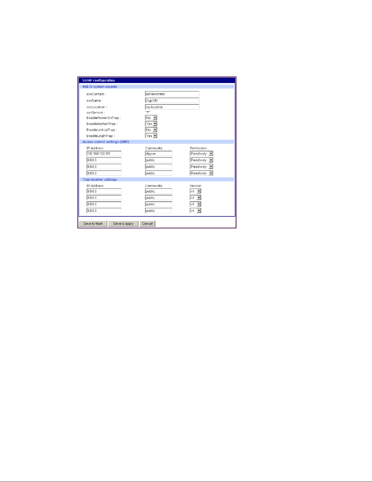
Alerts and notifications Manage the SNMP protocol
IP Address - Enter the IP address of the device receiving the trap alerts.
Community - The options are public or private.
Version - Choose the SNMP version, either version 1 or version 2c.
6 Click Save & apply.
Manage the SNMP protocol
The Digi CM unit ’s SNMP protocol can be managed using an NMS or SNMP browser. However, before
the NMS or SNMP browser can access the data, the Access control settings must list the IP address of
the host from which the browser is executed. See the preceding graphic for details.
Configure port event handling
Once an SMTP or SNMP server has been configured, it can be used to send port-related alerts and
notifications. The following describes how to configure a port for port event handling.
1 Access the web interface.
2 Choose Serial port > Configuration.
3 Choose a port to configure and then Port logging.
4 Select Enable.
Digi CM User Guide 60
Page 61

Alerts and notifications Configure port event handling
5 Choose Save & apply.
6 Choose Port event handling.
The following page appears.
Digi CM User Guide 61
Page 62

Alerts and notifications Configure alerts for Automatic Device Recognition (ADR)
7 Select an action and enter the keyword for the port event handling.
8 Enable Email notification.
Note It is assumed that SMTP is configured first. If not, see Configuring SMTP alerts.
9 Enter the title of the Email (subject line).
10 Enable or Disable Case sensitive.
11 Enter the Email recipient’s address.
12 Enable SNMP trap notification.
13 Enter the title of the trap.
14 Choose either to use the global SNMP settings by enabling "Use global SNMP configuration" or
specify special settings for this port.
15 Enter the IP address of the trap receiver.
16 Enter the SNMP community
17 Select the version.
18 Complete configuration and then choose Save & apply.
Note Key word is any text string that will trigger an alert when it traverses the serial port.
Configure alerts for Automatic Device Recognition (ADR)
Before configuring the alerts for Automatic Device Recognition, be sure you have configured the
port for ADR as described in Configure Automatic Device Recognition.
1 Access the web interface.
2 Under the Serial Port heading, Click Configuration.
3 Choose All or an Individual port > Alert Configuration.
4 Follow the Email Alert steps to configure the email alert or follow the SMTP Notification to
configure SMTP.
Email Alert SMTP Notification
Enable "Email Alert for active detection"
Enter the Title of email
Enter Name and email address where the
email should be sent.
Enable "Active detection trap"
Configure the trap receiver by one of the following
two ways:
Enter "Use global SNMP configuration" OR
Enter the IP address of the trap receiver, the SNMP
trap community and select the version
5 Complete configuration and choose Save & apply.
Digi CM User Guide 62
Page 63

User administration
Administer users . . . . . . . . . . . . . . . . . . . . . . . . . . . . . . . . . . . . . . . . . . . . . . . . . . . . . . . . . . . . . . . . . . 64
Digi CM User Guide 63
Page 64

User administration Administer users
Administer users
Required privileges
Only root and admin can administer users. The root user has unlimited administration privileges.
Admin can view and change all attributes except those that belong to the root user.
There are several ways to manage users. A user can be added, edited, or removed. Multiple users
can be managed in Groups or Access lists. The difference between Groups and Access lists are that
Groups are established in the operating system on the Digi CM unit and privileges are predefined
such as Root or Admin and are used most often for configuration. Access lists allow access to the
ports and are created by defining the privileges of the lists. Access Lists manage rights of multiple
users at the same time. Multiple users with the same rights are associated with an access list. This
allows the administrator to simplify the overall administrative process.
Procedure
1 Access the web interface.
2 Under System administration, choose Users administration. The following screen appears.
Note The username on the Digi CM unit is case sensitive.
3 Do one of the following:
To... Do the following...
Add a user 1. Click Add.
2. Fill in the attribute fields. See the table that follows for information on
attribute fields.
3. Click Add.
Edit a user 1. Click on the username.
2. Fill in the attribute fields. See the table that follows for information on
attribute fields.
3. Click Submit.
Digi CM User Guide 64
Page 65

User administration Administer users
To... Do the following...
Remove a user 1. Check the box that corresponds to the user you want to remove.
2. Click Remove.
3. Choose OK at the prompt.
Create an Access list 1. Under System administration, click Access List.
2. Enter the name of the Access List and click Add.
3. Click on the access list name to add users
4. Add the users to the access list
Note: The name field in the Access list allows you to add users that are
not locally configured on the Digi CM unit but use a centralized
authentication method like RADIUS, LDAP etc.
To change the privileges of an Access list, see Change the privileges of an
access list.
4 Click Apply Changes.
Add an Access List to the Digi CM Unit
1 Access the web interface of the Digi CM unit.
2 Under System Configuration choose Access Lists.
3 Enter the access list name into the edit-box and click [ADD].
4 A pop-up windows will appear confirming the successful addition of an access list. Now you can
add users to the access list by:
5 Click the name of the access list; a configuration windows will open.
6 Add one user at a time to the list by:
a. Entering the name into the edit-box and clicking [ADD].
CAUTION! Spelling is not verified against the local user database. This allows you to add
externally configured users that only exist in the RADISU, LDAP or other central
databases.
Digi CM User Guide 65
Page 66

User administration Administer users
After an access list has been added to the system, port rights can be associated with it. See
Configure security and authentication.
The following table describes the user fields.
Field Description
User name Name for the user, which must be between 3 and 29 characters and
cannot include colons (:), less than or greater than signs (< >),
ampersand (&), spaces, or quotation marks.
The at sign @ and period . are acceptable.
The username on the Digi CM unit is case sensitive.
Select group Group to which the user is assigned. Groups include Root, System
Admin, Port Admin and User. See User groups for more information
Password Password to assign to the user. This must conform to the rules
stipulated above for a user name.
Confirm password Confirms the password.
Shell program Interface presented to the user when he/she logs on to the system
from a Telnet or SSH connection.
SSH public key
authentication
SSH public key to use Current public file key or create a new public file key
Select new SSH public key
version
Select new SSH public key
file
Alternative method of identifying yourself to a login server.
More secure than just a password.
SSH1 only supports one type of key
SSH2 supports both RSA and DSA key types
Location for the SSH public key file
Digi CM User Guide 66
Page 67

Configure security and authentication
Introduction . . . . . . . . . . . . . . . . . . . . . . . . . . . . . . . . . . . . . . . . . . . . . . . . . . . . . . . . . . . . . . . . . . . . . 68
Configure network IP filtering . . . . . . . . . . . . . . . . . . . . . . . . . . . . . . . . . . . . . . . . . . . . . . . . . . . . . . . 68
Configure User Access Control . . . . . . . . . . . . . . . . . . . . . . . . . . . . . . . . . . . . . . . . . . . . . . . . . . . . . . . 72
Security Profile . . . . . . . . . . . . . . . . . . . . . . . . . . . . . . . . . . . . . . . . . . . . . . . . . . . . . . . . . . . . . . . . . . . 76
Authentication . . . . . . . . . . . . . . . . . . . . . . . . . . . . . . . . . . . . . . . . . . . . . . . . . . . . . . . . . . . . . . . . . . . 78
Configure authentication methods for port access . . . . . . . . . . . . . . . . . . . . . . . . . . . . . . . . . . . . . . 79
Configure authentication for the web server . . . . . . . . . . . . . . . . . . . . . . . . . . . . . . . . . . . . . . . . . . . . 80
Digi CM User Guide 67
Page 68

Configure security and authentication Introduction
Introduction
The Digi CM unit provides four methods for controlling access to the network and the devices on the
network:
▪ Restricting or permitting IP filtering
This method allows or prevents users with specific IP addresses from accessing devices or serial
ports on the network. IP filtering can be permitted or restricted for all ports globally or per port.
▪ Restricting or permitting specific users
You easily can add users to or remove them from a list of restricted or permitted users list.
▪ Enabling sniff session access
This method allows multiple users to access a single port.
▪ Using a central point (System administration > Security profile) where you establish security
parameters per network, port, or password.
The Digi CM unit supports several authentication methods, including:
▪ Local
▪ RADIUS
▪ TACACS +
▪ LDAP
▪ Kerberos (The Kerberos module is not part of the normal firmware because of memory
constraints. You can download the module from digi.com and place onto /usr2/ if required. To
copy files to /usr2/, use a scp tool such as WinSCP.)
▪ Custom PAM. You can configure authentication so that a secondary method is attempted if the
primary method fails.
Configure network IP filtering
The Digi CM unit offers built-in firewall functionality to limit TCP/IP traffic to and from certain
networks, TCP ports, and interfaces. The functionality implemented is based on the Linux tool IP
tables.
The next scenario shows that access to the device connected to the Digi CM is allowed only on the .1
subnet. The device at 192.168.1.108 can access the device connected to the Digi CM because it is in
the range allowed by the IP Filter rule.
Digi CM User Guide 68
Page 69

Configure security and authentication Configure network IP filtering
It is also possible to enable or disable specific services of the Digi CM unit by creating IP Filtering
rules:
Telnet co nsole (TCP/IP port 2 3)
SSH console (TCP/IP port 22)
Web configuration (TCP/IP port 80)
The fields are described next:
Interface - The name of the network interface through which a packet is received. The name can
be one of these values:
eth0: the default Ethernet interface of the Digi CM unit
eth1: the secondary interface added by using a PC card or wireless card
Digi CM User Guide 69
Page 70

Configure security and authentication Configure network IP filtering
all: both interfaces
Option - Determines that the rule will be applied to the IP address/Mask specified or its inverse;
that is, the rule will be applied to all except those specified.
Normal: applied to the hosts that are included
Invert: applied to the hosts that are excluded
IP address/Mask - Specifies the host range by entering base host IP address followed by “/” and
subnet mask. The host range can be one of the following scenarios by changing the value:
• Only one host of a specific IP address
• Hosts on a specific subnet
• Any host
Specified host range Input format
Any host 0.0.0.0/0.0.0.0
192.168.1.120 192.168.1.120/255.255.255.255
192.168.1.1 ~ 192.168.1.254 192.168.1.0/255.255.255.0
192.168.0.1 ~ 192.168.255.254 192.168.0.0/255.255.0.0
192.168.1.1 ~ 192.168.1.126 192.168.1.0/255.255.255.128
192.168.1.129 ~ 192.168.1.254 192.168.1.128/255.255.255.128
Protocol - The protocol that is being accepted on or dropped from the port:
• TCP
• UDP
• ICMP
Port - A TCP/IP port on the Digi CM unit that other hosts try to access. You can specify either one
port, using a single value, or a range of ports in this form
: port1:port2
where
port1 defines the lowest port and port2 the highest port.
Chain rule - Determines whether access from the hosts is allowed:
ACCEPT: Access allowed
DROP: Access not allowed
To add a new IP filtering rule, enter the values for the parameters and click the Add button on
the right side of the table.
To remove a rule, click the Remove button.
After you finish editing the table, save the settings to flash:
• To save your changes, use the Save to flash button.
• To save and apply your changes, use the Save & apply button.
Digi CM User Guide 70
Page 71

Configure security and authentication Configure network IP filtering
Be aware that you must apply the changes to make them active.
This screen shows five established IP rules.
This table describes the rules.
Rule Description
#1 Defines SSH access to the Digi CM unit (port 22).
▪ The Normal option specifies that the rule applies to all addresses listed.
▪ The rule says to Accept traffic from these addresses for Port 22.
#2 Defines Telnet access to the Digi CM unit (port23).
▪ The Invert option specifies that the rule applies to all addresses except those listed.
▪ The rule says to Drop traffic from all addresses not listed.
#3 Define access to the Digi CM unit using HTTP (port 80).
▪ Rule 3 blocks all traffic.
▪ Rule 4 allows access from IP address 192.168.1.0.
▪ Rule 5 allows access from IP address 192.168.2.0.
Allowable Hosts Input format
Base Host IP Address Subnet mask
Any host 0.0.0.0 0.0.0.0
192.168.1.120 192.168.1.120 255.255.255.255
192.168.1.1 - 192.168.1.254 192.168.1.0 255.255.255.0
192.168.0.1 - 192.168.255.254 192.168.0.0 255.255.0.0
192.168.1.1 - 192.168.1.126 192.168.1.0 255.255.255.128
192.168.1.129 - 192.168.1.254 192.168.1.128 255.255.255.128
Digi CM User Guide 71
Page 72

Configure security and authentication Configure User Access Control
Configure User Access Control
Another method for controlling access to the serial ports on the Digi CM unit is the User Access
Control configuration. You can set up this configuration either globally (using the All Ports option) or
per port.
It is not necessary to have users added to the system to assign rights. However, for the permissions
or restrictions to be enforced, the username must match exactly. The username is case sensitive,
and the application does not recognize misspellings.
To add users, click on "System administration > Users administration". For details about adding
users, see User administration.
Note Users do not need to be authenticated locally; they can be users on any configured
authentication server.
Using Access lists, you can add rights to a single user or to multiple users at the same time. In
addition, you can group multiple users and assign one, some, or all these rights:
▪ Port access rights
▪ Port monitor rights
▪ Power management rights to an access list.
For more information, see Create an Access list.
This scenario shows a configuration with a restricted user: Joe does not have access to the Sun
server, while Mike does.
Your strategy for assigning rights to a port can include:
▪ Allowing <<Everyone>> access to a port and then restricting access to certain users -or-
▪ Specifying each individual user and their specific rights to a port.
▪ Adding a user to an established group (Access list) with preconfigured rights to a port.
Digi CM User Guide 72
Page 73

Configure security and authentication Configure User Access Control
If you check <<Everyone>>, all users, whether they are configured locally or are using a remote
authentication (such as LDAP or Kerberos), have access to this port.
If you do not check <<Everyone>>, no users are allowed to access this port unless they are
individually listed.
When you enter usernames for access permissions or restrictions, you must enter the username
exactly as the username on the remote authentication server or configured locally. The username is
case-sensitive.
In the next example, three users are configured on the Digi CM unit: Jeff, Tim and Paul. To give Tim
and Paul read/write access and power access to this port, you could either:
▪ Grant rights to Paul and Tim
▪ Restrict Jeff’s rights
▪ Add users to an Access list (in this example. sun-users) found under System administration >
Access list. For more information, see Create an Access list.
Configure user access privileges
To configure user access privileges:
1 Select Serial Port Configuration > All Ports (or Port #)
2 Click User access mode
3 Enter the users and their privileges, and click Add user.
Digi CM User Guide 73
Page 74

Configure security and authentication Configure User Access Control
Restrict a user’s privileges
To restri ct user a cce ss:
1 Under Port configuration > User access control
2 Enter privileges for <<Everyone>>.
3 Enter restricted user’s name (Here it is Jeff).
4 Enter the privileges this user has. (Notice that <<Everyone>> has more access than Jeff does.)
Note The usernames and passwords on the Digi CM unit are case-sensitive. Notice <<Everyone>>
has access to Port, Monitor, and Power, while Jeff has access to only Monitor, with no Port or
Power access.
Change the privileges of an access list
1 On the same screen shown in the previous procedure, select an access list from the drop-down
box.
2 Click the Add access button, and then click and the Save & apply button. When you add the
access list, it will include Paul and Tim.
Digi CM User Guide 74
Page 75
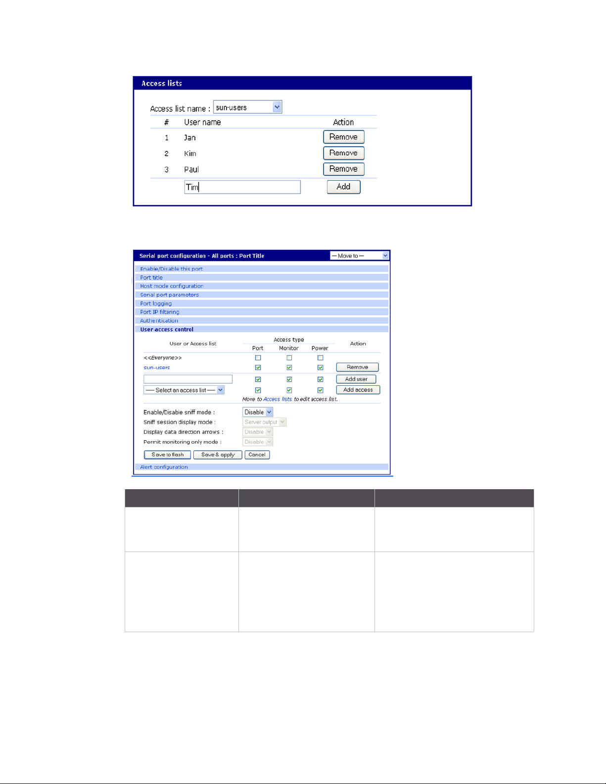
Configure security and authentication Configure User Access Control
In this screen, the "sun-users" Access group has access to Port, Monitor, and Power, while any other
users (<<Everyone>>) do not have access.
Type of users Access types How to permit or restrict
Only specific users have
access "Permitted Users"
All users have access
except for a few
"Restricted Users"
Access type is unchecked for
Everyone (meaning All other
users) does not have access
Everyone has access to
everything by checking the
access types. If an access type
is unchecked, all users are
restricted from that access
type.
By listing specific users and checking
the access types - (Permitting them
access)
By listing users and unchecking the
access type they are restricted from
using
Sniff session
A sniff session enables multiple users to access a single serial port for viewing the data stream.
Anyone who is registered for a sniff session can access a specific serial port — even if someone else is
using the port. The Digi CM unit supports multiple concurrent sniff sessions.
Digi CM User Guide 75
Page 76
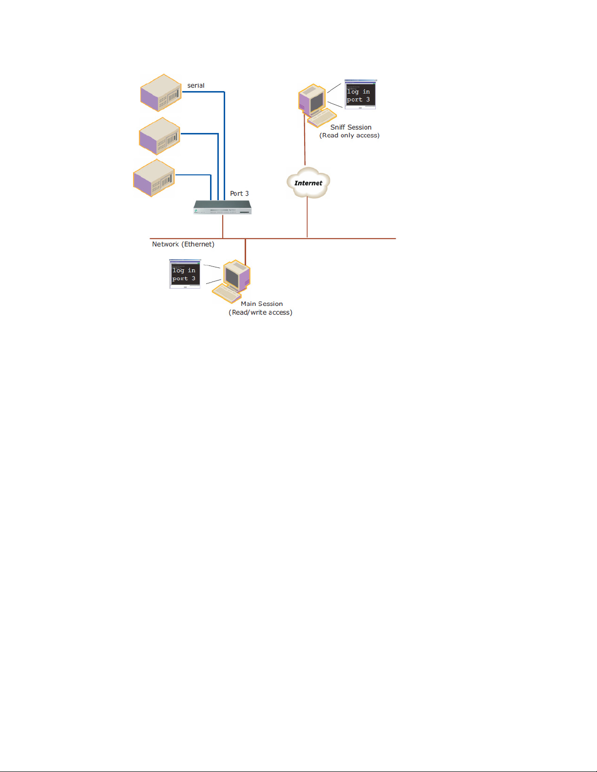
Configure security and authentication Security Profile
Sniff session mode has four options: disabled, input, output, and both. You configure the sniff
session modes per port from the serial port configuration page.
Enable/Disable sniff mode
▪ Disabled - No one can enter a sniff session after the first user logs on.
▪ Enabled - Allows all users with access the following options in sniff mode:
Sniff session display mode
▪ server output - View all data to a serial port from a remote connection
▪ user input - View all data from a serial port to a remote connection
▪ both - See all data transmitted or received through a serial port
Display data direction arrows
▪ Enable/Disable - Displays arrows to indicate the direction of data to or from the server. When the
second user accesses the port, the global "Port escape menu" is displayed. See Port escape
menu.
Permit monitor only mode
▪ Enable: A user with “Monitor" permissions can only connect to the port in read only mode any
time.
▪ Disable: A user with “Monitor" permissions can connect if a read/write user has a connection to
the port. A read-only session is automatically disconnected if the main user (read/write session)
disconnects from the port.
Security Profile
The Security Profile tab, available under System Administration > Security Profile, provides a
centralized access for enforcing site-appropriate, minimum security parameters on the CM. These
are the available control mechanisms:
▪ System Security
Digi CM User Guide 76
Page 77

Configure security and authentication Security Profile
▪ Password Security (Force heightened)
System security
▪ SNMP
The CM allows you to use Get and Set commands for easy remote configuration and monitoring. You
can configure Get and Set individually using the Network > SNMP Configuration interface.
This option gives you a simple method for globally disabling any SNMP queries. (Traps always can
be sent if they are configured). In the Default configuration, SNMP is disabled.
▪ Discovery (ADDP)
Enables/disables the discovery protocol. While this is convenient for initial discovery of units on the
network, this service is often disabled when the system is ready for production, unless the system is
deployed on a controlled LAN.
▪ Te ln et
Disabled by default, this feature can be enabled afterward if the customer does not plan to use
network security.
▪ SSH
Usually remains enabled; in some environments, however, access is allowed only by a totally out-ofband connection (hard-wired serial, dial-up modem, or both). In such situations, the Ethernet
connection is used only for reports and alerts.
▪ SSHv1
SSHv1 (Secure Shell Version 1). SSHv1 uses server and host keys to authenticate systems. This
service is disabled by default.
▪ HTTP
Enables/disables access to the Digi CM using the Web interface. By default, HTTP is redirected to
HTTPS.
▪ HTTPS
Enables/disables access to the Digi CM using the Web interface. This service is enabled by default. If,
however, the unit will be deployed outside a controlled LAN, HTTPS is often disabled to limit the
number of services available.
▪ All Ports
Enables/disables access to all ports using any protocol.
▪ Set all ports to
Specifies the protocol to be used on all ports. The default is Telnet.
▪ Stealth Mode
Makes the Digi CM “invisible” on the network and exposes only ports that are used to provide
access. In Stealth Mode, the CM does not reply to pings or traceroutes and does not respond to
communication attempts on unused TCP/UDP sockets.
Password security
To enhance password security, you can use these settings:
▪ Minimum password length - Allows passwords that are 3 to 255 characters long; also allows
spaces in passwords
Digi CM User Guide 77
Page 78

Configure security and authentication Authentication
▪ Maximum password age - Specified in days. To disable this setting, enter 0.
▪ Enforce password complexity - Cannot include all or part of a user’s account name. Passwords
must be at least eight characters long. If you enable Minimum Password Length, passwords can
be 8-255 characters long and must include three of these four categories of characters:
• English uppercase characters (A-Z)
• English lowercase characters (a-z)
• Base 10 digits (0-9)
• Non-alphabetic characters (!, $, #, %, and so on)
▪ Enforce password history - Cannot reuse the last nine passwords
Authentication
The Digi CM unit supports multiple methods of user authentication, including local, TACACS+,
RADIUS, RADIUS Down-Local, LDAP, Kerberos, and Custom PAM. The authentication protocol you
use depends on your environment.
Digi CM User Guide 78
Page 79

Configure security and authentication Configure authentication methods for port access
Configure authentication methods for port access
You can choose between having a single authentication method, such as RADIUS, or an
authentication method where a Local authentication service is used in addition to the RADIUS,
LDAP, TACACS+ server, or Kerberos. These options are listed when you configure the Digi CM unit for
authentication. To configure the Digi CM unit for authentication, do the following:
1 Access the web interface.
2 Under the Serial port heading, choose Configuration.
3 Choose All or an Individual port > Authentication.
4 From the drop-down menu, choose an authentication method. A configuration screen for the
authentication method you choose is displayed. This figure displays the options for setting up a
RADIUS server as the primary authentication server and Local authentication if the primary
authentication method fails.
Note Remote authentication to Port access menu can be obtained from Serial port >
Configuration > Port access Menu
5 Fill in the applicable fields.
Digi CM User Guide 79
Page 80
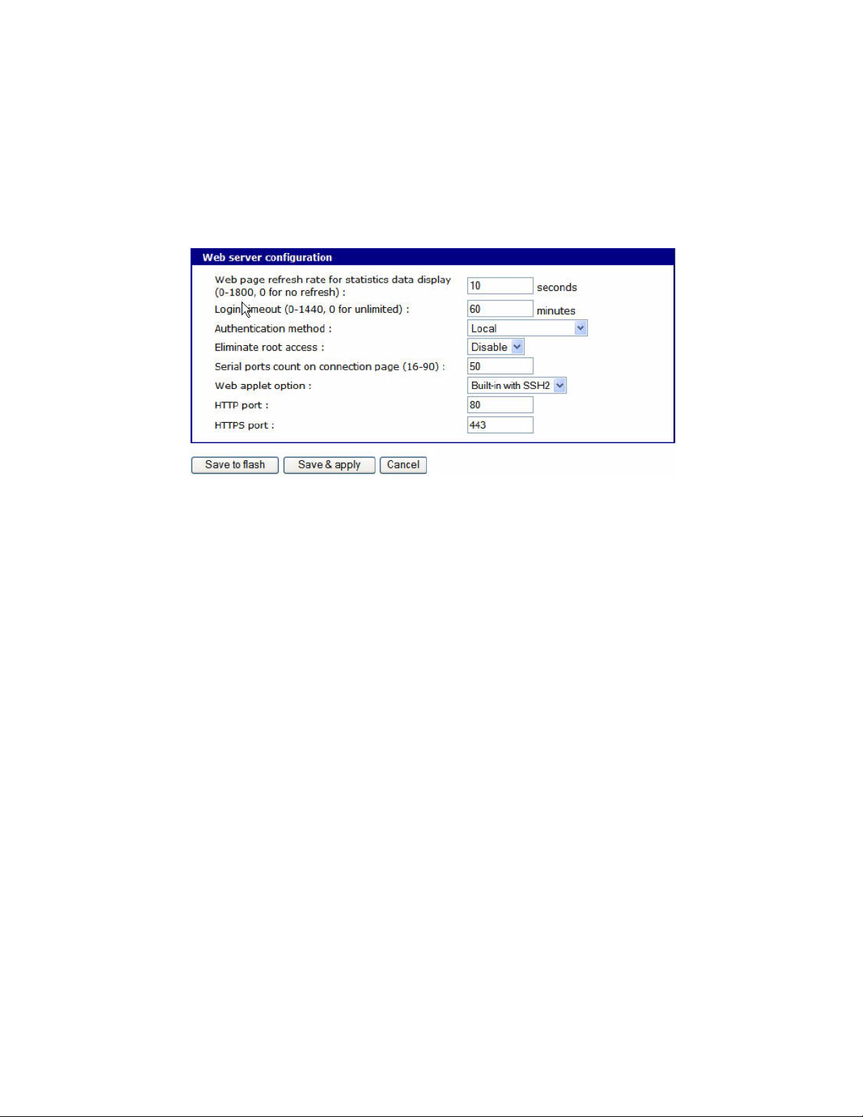
Configure security and authentication Configure authentication for the web server
6 Choose Save & apply changes.
Configure authentication for the web server
1 Access the web interface.
2 Choose Network > Web server configuration.This screen opens.
3 Choose an authentication method and then Save & apply.
When you are using remote authentication for the web server, such as RADIUS, RADIUS Down-local,
TACACS+, LDAP, Kerberos, or Custom PAM, you must also be added to the local database. The user
password must be different from local authentication; otherwise, the CM will authenticate against
the local database instead of the remote one. For details, see User administration.
When your password is approved by the authentication server, the Digi CM unit uses the local
permission rights to provide access privileges for you to ports and the configuration.
LDAP authentication
The Digi CM unit supports authenticating against an LDAP-based database, including LDAP systems
running on Linux servers as well as Microsoft Active Directory together with the LDAP gateway ADAM
(Active Directory Application Mode).
If the Digi CM unit authenticates against an LDAP directory, all users must be configured in one
container. The Digi CM unit will extend the username using the LDAP search base and authenticate
the user.
In the next example, the domain is called dilbert.com, the LDAP server is at 10.1.1.1, and all users
with access to the Digi CM unit are located in the container: USA Users
Configure the LDAP authentication as shown here:
Authentication method: LDAP server
First LDAP Server 10.1.1.1
Second LDAP Server
LDAP search base: ou=users,ou=usa,dc=dilbert,dc=com
Domain name for active directory:
If your LDAP database resides on a Microsoft system you also have to configure the Domain name for
the active directory (dilbert.com in the above example).
Digi CM User Guide 80
Page 81

Configure security and authentication Configure authentication for the web server
Do not use this setting if you are using a non-Microsoft system as it changes the LDAP to comply with
Microsoft syntax.
Custom PAM module
The Digi CM unit supports custom PAM modules for remote authentication. This allows you to create
your own authentication schema or use any other third party PAM module. The module must o be
compiled for the Digi CM unit’s environment.
Digi offers an SDK for the Digi CM family.
To download the SDK, contact technical support at support.wizards@digi.com.
1 Place the custom PAM modules onto: /usr/2 on the Digi CM unit.
2 Use an scp client (like WinSCP) to copy data to the /usr2 directory, or download the ftp client for
the Digi CM unit from support.digi.com.
3 Make sure the module is flagged to be executable (chmod 755 ...)
Note To activate the custom PAM module it has to be configured in the custom file located in /etc/
pam.d
4 Create a file called: /etc/pam.d/custom and add these lines:
auth required /usr2/my_pam _auth.so
session required /usr2/my_pam_ auth.so
(with the my_pam_auth.so being the "custom pam" module’s name)
To keep this file permanently copy it to /usr2 and add a line to /usr2/rc.user.
Cp /usr2/custom /etc/pam.d/
Example of an rc.user file:
#!/bin/bash
#
# rc.user : Sample script file for running user programs at boot
time
#
#PATH=/bin:/usr/bin:/sbin:/usr/sbin
# Add shell command to execute from here
cp /usr2/custom /etc/pamd/
exit 0
Digi CM User Guide 81
Page 82

Custom and default menus
Introduction . . . . . . . . . . . . . . . . . . . . . . . . . . . . . . . . . . . . . . . . . . . . . . . . . . . . . . . . . . . . . . . . . . . . . 83
Make custom menus . . . . . . . . . . . . . . . . . . . . . . . . . . . . . . . . . . . . . . . . . . . . . . . . . . . . . . . . . . . . . . . 83
Default menu . . . . . . . . . . . . . . . . . . . . . . . . . . . . . . . . . . . . . . . . . . . . . . . . . . . . . . . . . . . . . . . . . . . . . 86
Digi CM User Guide 82
Page 83

Custom and default menus Introduction
Introduction
The Digi CM unit has several default menus for easy configuration and access by different users.
Depending on access privileges, the menus available are the Web Interface, Configuration Menu,
and Port Access Menu. A Custom Menu feature for creating menus is also available through the web
interface.
The Custom Menu feature enables system administrators to create menus for specific users; in other
words, system administrators can create a customized interface to selected ports. Custom menus
can only be configured via the web however, they can only be accessed via the shell (command line).
Make custom menus
Before making custom menus, plan the kind of menus and menu items you want available to your
users. A good plan would include the following:
1 Add users to the system.
2 Create a menu name with sort and display features.
3 Add menu items and submenus to the new menu.
4 Assign users to the menus.
Add users
You cannot assign users to a menu until you have added users to the system. To add users, do the
following:
1 Access the web interface.
2 System administration > Users administration > Add
3 Enter the User name and User group from the drop down menu. Select Custom menu from the
drop down menu for the Shell program.
Digi CM User Guide 83
Page 84

Custom and default menus Make custom menus
4 Click Add to add the user.
5 Continue to add users as needed.
Note You do not need to Save to flash or Apply changes to add users.
Create menu names
To make a custom menu, do the following:
1 Access the web interface.
2Custom Menu > Configuration.
3 Enter the Menu Name to assign and click the Add Menu button.
The menu is added.
4 Click the hyperlink to the menu you just created.
5 From the drop down menu, select the way to Sort and Display items.
6 Click Save & apply.
7 Repeat as required to create additional menus.
Digi CM User Guide 84
Page 85
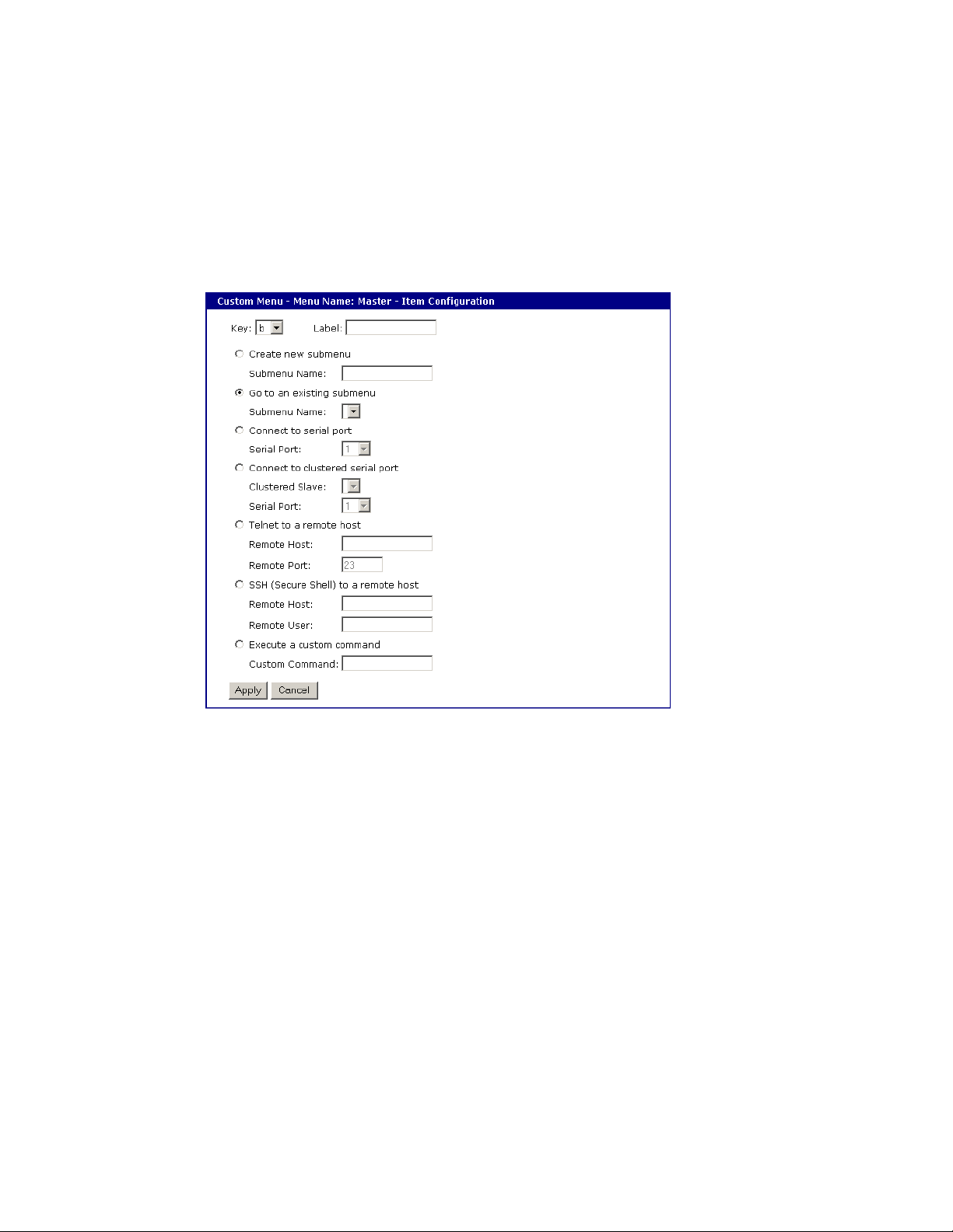
Custom and default menus Make custom menus
Add menu items
Once you have defined a menu name and added users, you can then add menu items. To add menu
items, do the following:
1Custom Menu > Configuration > Menu Name hyperlink for the menu you want to configure.
2 Choose Menu Items > Add Item.
The following screen appears.
3 Fill in the desired parameters. The parameters are:
Key - Assign any letter or number except a value already used by another menu item.
Label - Assign a label or name for the menu item.
Create new submenu - Assign a name for a new submenu that this menu item will be assigned
or linked to.
Go to existing submenu - Choose an existing submenu from the drop down menu that this
menu item will be assigned or linked to.
Connect to serial port - Connects you to a specified port.
Connect to clustered serial port - Connects you to a clustered port.
Telnet to a remote host - Enter a remote host’s IP address or hostname.
SSH (Secure Shell) to a remote host - Enter the hostname or IP address of a remote host and
the remote username.
Execute a custom command - Enter a customized command that is any valid command on the
command line with acceptable user privileges.
4 Choose Apply.
5 Repeat this procedure to add more menu items.
Digi CM User Guide 85
Page 86

Custom and default menus Default menu
Note To add or configure submenus, select the Submenus hyperlink on the Menu Configuration
page.
Assign users to a menu
Once a menu has been created, users can be assigned to the menu by doing the following:
1 Access the web interface.
2 Configuration > Custom Menu > Menu Users.
A list of available users is displayed.
3 Choose a menu for a user by selecting a menu from the drop down Assigned Menu list.
4 Choose Save & apply.
Default menu
Port Access menu
The Port Access menu is a flat (one level) menu showing all ports, port titles and the mode of each
port.
Using the Port Access menu you have a complete overview of all ports and can initiate a connection
to any of them.
When you choose to connect to a specific port, you are prompted again for the username and
password.
There are multiple ways to access the PortAccess menu:
▪ Assigned IP address (see Configure host mode)
▪ TCP/IP port 7000
Digi CM User Guide 86
Page 87

Custom and default menus Default menu
▪ TCP/IP port 22 or 23 if the “Shell program” is set to “port access menu” for this specific user (see
User administration)
▪ By calling “portaccessmenu” from the command line
The PortAccess menu allows simple access to each port.
By typing the number of the port to connect to, the Digi CM unit initiates a connection to this port
using the appropriate protocol (Telnet of SSH).
You can also change your own password by using the “P” Key.
If the Digi CM unit is configured to be the master in a master-slave scenario, the “S” key will bring up
a list of all slaves. Selecting a slave will then spawn a connection to the Port Access Menu of the
slave.
When using a Digi CM 48, not all ports can be displayed on one screen. Ports 33-48 can be viewed
after hitting the <Enter> key.
Digi CM User Guide 87
Page 88

Microsoft SAC support
About the Digi CM Unit’s support for Microsoft Windows Server 2003 . . . . . . . . . . . . . . . . . . . . . . . 89
Setup the Windows Server 2003 port . . . . . . . . . . . . . . . . . . . . . . . . . . . . . . . . . . . . . . . . . . . . . . . . . . 90
Setup the Digi CM Unit for SAC support . . . . . . . . . . . . . . . . . . . . . . . . . . . . . . . . . . . . . . . . . . . . . . . . 90
Access the Windows Server 2003 Console port from the Digi CM Unit’s GUI . . . . . . . . . . . . . . . . . . . 92
Digi CM User Guide 88
Page 89

Microsoft SAC support About the Digi CM Unit’s support for Microsoft Windows Server 2003
About the Digi CM Unit’s support for Microsoft Windows Server 2003
The Digi CM unit provides a browser-based user interface to Microsoft’s text-based Special
Administration Console (SAC), an integral part of Windows Server 2003 Emergency Management
Services (EMS). Both the English and Japanese versions of SAC are now supported. When a server
running Windows Server 2003 is connected to the Digi CM unit’s serial port, key SAC functions-normally accessed from the command line--are available from a graphical user interface (GUI). SAC
features accessible from this interface include:
▪ Reset and shutdown
▪ Show performance values like memory utilization
▪ Show and configure IP settings per interface
▪ Show the process list and kill processes
Note While the EMS port is available at all times using Telnet or SSH, the special GUI is available
only while SAC is active.
Setup overview
Setup for the Digi CM unit SAC support is a three-step process:
1 Set up the Windows Server 2003 for SAC support. To do this, ensure that the COM port used for
console traffic is properly set up. This includes designating a COM port for console
communication and setting the port speed (baud) appropriately. For further information see
Setup the Windows Server 2003 port below.
Digi CM User Guide 89
Page 90

Microsoft SAC support Setup the Windows Server 2003 port
2 Cable the console port on the Windows Server 2003 to the Digi CM unit’s port. See the
information in About serial port cabling.
3 Set up the Digi CM unit for SAC support. See Setup the Digi CM Unit for SAC support.
Setup the Windows Server 2003 port
1 Sign on to the Windows Server 2003 as the administrator.
2 Access the command line.
3 Use the bootcfg command to redirect console traffic to the correct COM port. The following is the
command syntax and an example. See the Microsoft documentation for additional information
on the SAC feature.
Command syntax
bootcfg /ems on /port com# /id # /baud 115200
where:
▪ com# is the COM port to which console traffic will be redirected.
▪ # is the is the number of the boot entry.
▪ The port speed is set to the recommended rate (although you can use any rate supported by
Windows Server 2003).
Command example
In this example, console output is redirected to COM 2, the boot entry is specified as 1, and the port
speed set to 115200.
bootcfg /ems on /port com2 /id 1 /baud 115200
Setup the Digi CM Unit for SAC support
To set up a serial port to provide access to the Windows Server 2003 console port, do the following:
1 Access the web interface.
2 Choose Serial port > Configuration.
3 Choose a port.
4 Choose Host mode configuration.
The Host mode configuration page appears.
5 Set the Host mode to Console server and the Type of console server to MS SAC -English (or
Japanese) console as shown in the following figure.
Digi CM User Guide 90
Page 91

Microsoft SAC support Setup the Digi CM Unit for SAC support
6 Set other fields as appropriate.
7 Click Save & apply.
8 Configure serial port communication settings, by doing the following:
a. Choose Serial port parameters from the menu.
b. Adjust settings as required. This includes ensuring that the Baud rate matches the setting on
the Windows Server 2003 serial port and Flow control is set to None. Ignore the DTR behavior
field.
c. Click Save & apply.
Digi CM User Guide 91
Page 92
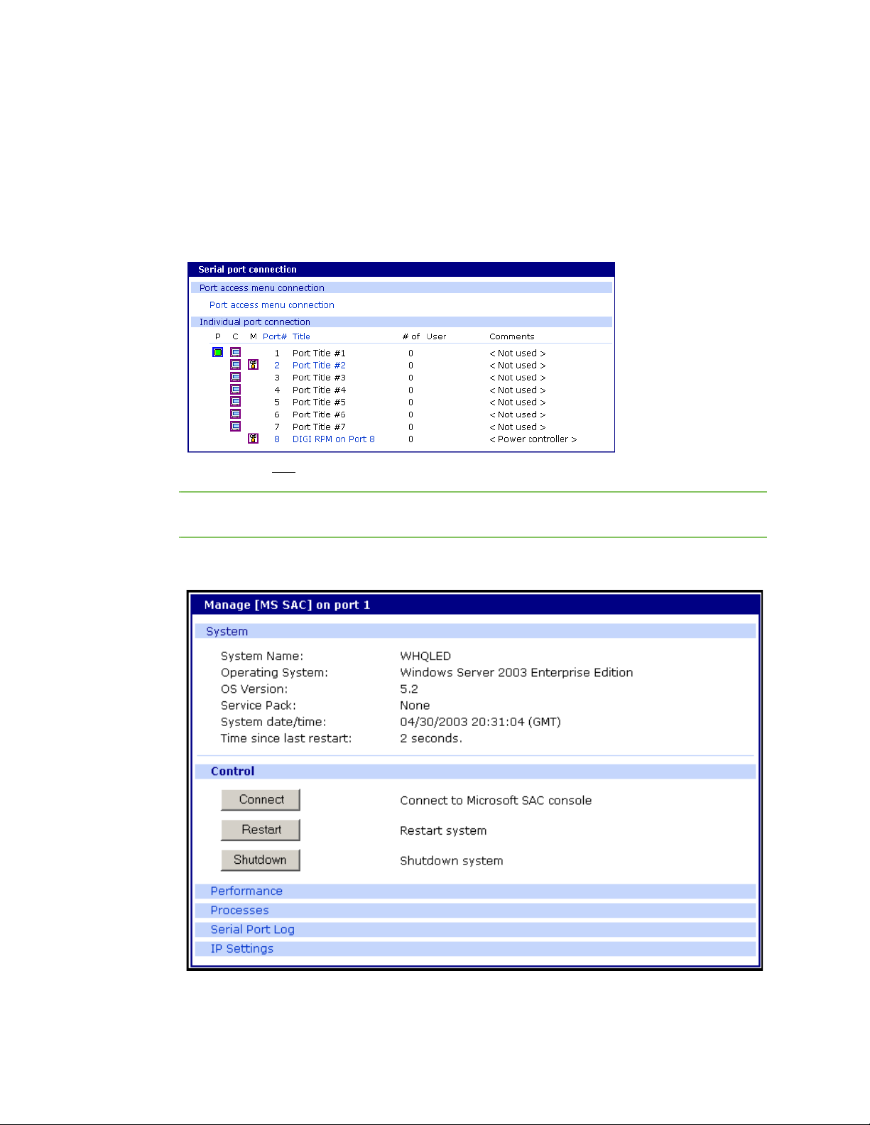
Microsoft SAC support Access the Windows Server 2003 Console port from the Digi CM Unit’s GUI
Access the Windows Server 2003 Console port from the Digi CM Unit’s GUI
To access the Windows Server 2003 console port, do the following:
1 Access the web interface.
2 Choose Serial port > Connection.
A screen similar to the following appears.
3 Click on the title
Note If support for "Windows Server 2003" and "Rackable Systems Management Card" is selected
a menu will appear and you must choose between the two functions.
A screen similar to the following appears.
of the port to which the Windows Server 2003 console port is connected.
4 Use the Digi CM unit’s GUI to perform SAC functions. The following table describes attributes of
the controls on the GUI.
Digi CM User Guide 92
Page 93

Microsoft SAC support Access the Windows Server 2003 Console port from the Digi CM Unit’s GUI
Field Description
Connect Connects to the SAC console port via the command line interface.
Restart Reboots the Microsoft Server 2003.
Shutdown Shuts down the Microsoft Server 2003.
Caution! This switches off the server and you can no longer access it remotely.
Performance Provides access to Microsoft Server 2003 status information.
Process Provides access to the process list, which allows you to view and kill active
processes.
Serial Port Log Provides access to port logging information.
IP Settings Provides access to IP settings, enabling you to verify and change settings.
Digi CM User Guide 93
Page 94

Configure virtual KVM
Introduction . . . . . . . . . . . . . . . . . . . . . . . . . . . . . . . . . . . . . . . . . . . . . . . . . . . . . . . . . . . . . . . . . . . . . 95
Use Virtual KVM with Remote Desktop protocol . . . . . . . . . . . . . . . . . . . . . . . . . . . . . . . . . . . . . . . . . 96
Use Virtual KVM with VNC protocol . . . . . . . . . . . . . . . . . . . . . . . . . . . . . . . . . . . . . . . . . . . . . . . . . . . 99
Use Virtual KVM with X Window System Protocol and XManager software . . . . . . . . . . . . . . . . . . . 102
Virtual KVM Assistant . . . . . . . . . . . . . . . . . . . . . . . . . . . . . . . . . . . . . . . . . . . . . . . . . . . . . . . . . . . . . 105
Install programs for Virtual KVM . . . . . . . . . . . . . . . . . . . . . . . . . . . . . . . . . . . . . . . . . . . . . . . . . . . . . 106
Digi CM User Guide 94
Page 95

Configure virtual KVM Introduction
Introduction
The Digi CM unit provides a method for gaining access to the graphical interface of a system using
the network. Using this method, Virtual KVM, you specify a connection method and IP address to use
to reach the system.
Supported methods include:
▪ Microsoft Remote Desktop Protocol
▪ VNC
▪ XManager for X Window System
▪ A user-defined option
An example configuration
This diagram shows the Digi CM managing a Linux SuSE 9.2 system, a Windows 2003 system, and an
HPUX system.
Virtual KVM protocols
This table lists the Virtual KVM protocols and the client software with which each protocol has been
tested.
Virtual KVM protocol Tested client softwar e
Remote Desktop Windows 2000, XP, 2003 Remote Desktop Client
Linux: rdesktop
VNC Windows: tightVNC, realVNC, UltraVNC
Linux: vncviewer
X Window System Windows: Xmanager
Linux/Unix: X Window System
The rest of this section describes how to set up Virtual KVM with each of the supported methods and
connect to a system through Virtual KVM.
Digi CM User Guide 95
Page 96

Configure virtual KVM Use Virtual KVM with Remote Desktop protocol
Use Virtual KVM with Remote Desktop protocol
This section describes how to:
▪ Configure Virtual KVM with Remote Desktop Protocol
▪ Connect to a system through Virtual KVM using Remote Desktop Protocol
Configure
To set up Virtual KVM with Remote Desktop protocol, follow this procedure:
1 Access the Digi Passport Web interface and log in.
2 Choose Serial Port > Configuration.
This window opens:
3 Choose the port you want to configure, and then select the Virtual KVM tab. (In this example, port
1 is selected.)
A window similar to this one opens, showing the serial port number and title:
Digi CM User Guide 96
Page 97
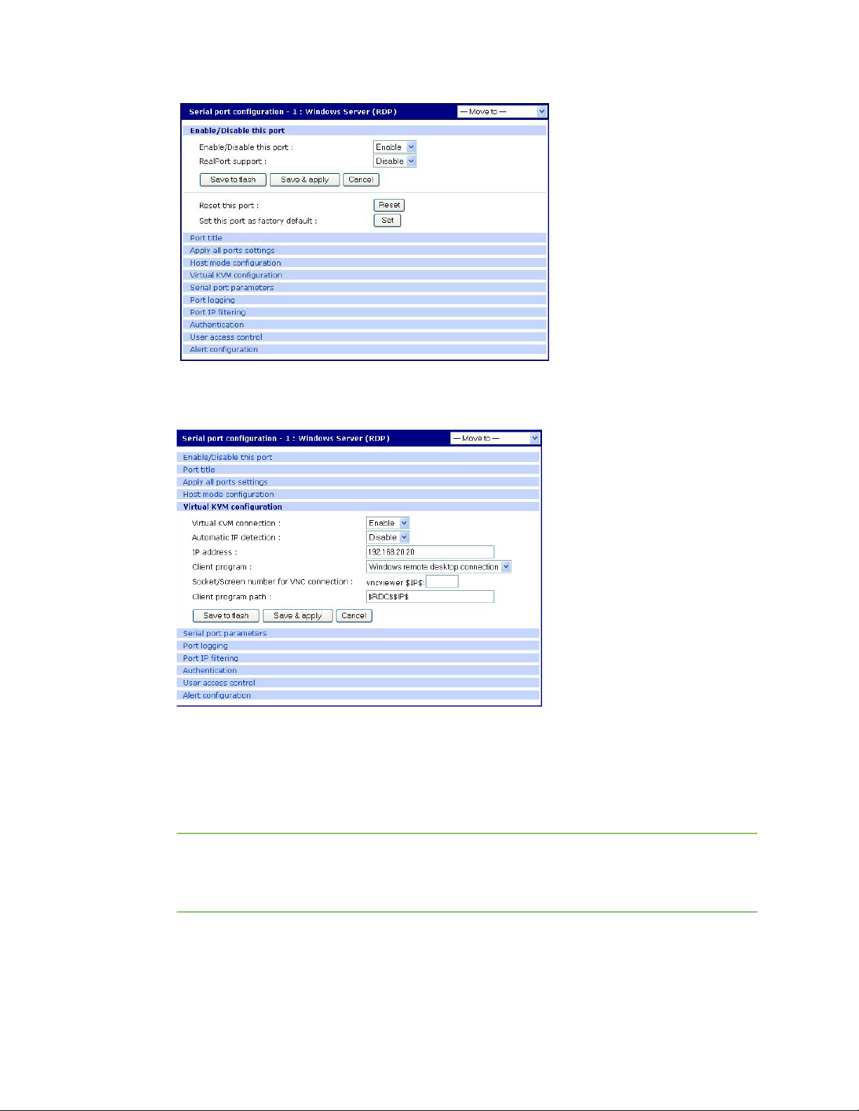
Configure virtual KVM Use Virtual KVM with Remote Desktop protocol
4 Click Virtual KVM configuration.
This window opens:
5 From the drop-down list next to Virtual KVM configuration, select Enable.
6 Then, from the Client program drop-down list, select Windows remote desktop connection.
7 If you are not using IP automatic detection, enter the IP address.
8 Click the Save & Apply button.
Note If you are using Remote Desktop configuration and you want to use automatic IP address
detection, configure the host mode for the port to MS SAC console before you configure the
Virtual KVM feature for the port. For more information, see Setup the Digi CM Unit for SAC
support.
Digi CM User Guide 97
Page 98

Configure virtual KVM Use Virtual KVM with Remote Desktop protocol
Connect to a system through Virtual KVM using Remote Desktop protocol
When you connect through the Connection window, and a Virtual KVM connection is configured, you
now see:
▪ The terminal monitor button, which connects to the raw ASCII SAC console
▪ A mouse button (next to the monitor icon), which connects to the Virtual KVM graphical interface
▪ The manage button, which connects to the SAC GUI screen
To connect through Virtual KVM using Remote Desktop, follow these steps:
1 Click on the mouse icon.
2 Click OK in each of the three Java confirmation request windows.
The applet first checks whether the optional Virtual KVM Assistant is installed on the system.
Then:
• If the applet is installed, it starts Virtual KVM Assistant to manage the connection.
• If the applet is not installed, the attempt to launch the Virtual KVM assistant fails, and the
applet tries to launch the connection directly.
• If the Virtual KVM Assistant is not installed, a message indicates that the first connection
attempt failed. A second message indicates that the second connection attempt succeeded.
This is normal behavior if the applet does not find the Virtual KVM Assistant. For more
information, see Virtual KVM Assistant.
The application starts and you see a message that the connection succeeded:
Digi CM User Guide 98
Page 99

Configure virtual KVM Use Virtual KVM with VNC protocol
This login screen opens:
3 Enter your user name and password, and then click OK.
If the application does not start, check to make sure that the application is in the search path on
your server. See Install programs for Virtual KVM.
Use Virtual KVM with VNC protocol
This section describes how to:
▪ Configure Virtual KVM with VNC Protocol
▪ Connect to a system through Virtual KVM using VNC Protocol
Configure
To configure Virtual KVM with VNC protocol, follow this procedure:
1 Access the Digi Passport Web interface and log in.
2 Choose Serial Port > Configuration.
This window opens:
Digi CM User Guide 99
Page 100

Configure virtual KVM Use Virtual KVM with VNC protocol
3 Double-click the port you want to configure.
A window similar to this one opens, showing the serial port number and title:
4 Select the Virtual KVM tab.
This window opens:
Digi CM User Guide 100
 Loading...