

Page 1

LxNETES™ User’s Guide
ConnectCore 9P 9360/9750
Page 2

Page 3

Digi International Inc. 2005. All Rights Reserved.
The Digi logo is a registered trademarks of Digi International, Inc.
All other trademarks mentioned in this document are the property of their respective owners.
Information in this document is subject to change without notice and does not represent a commitment on the part of Digi
International.
Digi provides this document “as is,” without warranty of any kind, either expressed or implied, including, but not limited to, the
implied warranties of fitness or merchantability for a particular purpose. Digi may make improvements and/or changes in this
manual or in the product(s) and/or the program(s) described in this manual at any time.
This product could include technical inaccuracies or typographical errors. Changes are periodically made to the information
herein; these changes may be incorporated in new editions of the publication.
Page 4

Page 5

••
Contents
••••••••••••••••••••••••••••••••••••••••••••••••••••••••••••••••••••
Chapter 1 Introduction........................................................................9
Overview..................................................................................................................9
Cross-development environment.......................................................................9
Linux kernel sources........................................................................................10
Template project ..............................................................................................10
Example applications.................................................................................10
Features..................................................................................................................11
What’s new in LxNETES 3.2? ........................................................................11
Linux Kernel..............................................................................................11
Bootloader..................................................................................................11
Tool chain ..................................................................................................11
General features...............................................................................................11
Conventions used in this manual.....................................................................13
Acronyms and abbreviations ...........................................................................14
Chapter 2 Requirements ...................................................................15
System Requirements/Prerequisites.......................................................................15
System requirements........................................................................................15
Disk space........................................................................................................16
Applications & Services ..................................................................................17
TFTP daemon ..................................................................................................17
NFS server .......................................................................................................18
JTAG-Booster..................................................................................................19
Chapter 3 Getting Started .................................................................21
Introduction............................................................................................................21
Connecting host PC with development board..................................................21
Step 1: Connect serial port.........................................................................21
Step 2: Connect Ethernet interface ............................................................21
Step 3: Configure terminal client...............................................................21
Minicom...........................................................................................................22
Seyon ...............................................................................................................22
Step 4: Connect power...............................................................................23
Step 5: Test Ethernet configuration ...........................................................24
Installing LxNETES ..............................................................................................25
Guided Installation.................................................................................................26
5
Page 6

Manual Installation................................................................................................27
Chapter 4 Building the First Project................................................. 29
Building the Default Project..................................................................................29
Step 1: Run configure................................................................................29
Example: .............................................................................................29
Step 2: Run make.......................................................................................30
Step 3: Run make install............................................................................30
Chapter 5 Application Development................................................ 31
Writing applications...............................................................................................31
Adding your own applications.........................................................................31
Example: .............................................................................................31
Using C++........................................................................................................32
Included example applications ..................................................................32
display........................................................................................................32
Debugging applications .........................................................................................34
Included pre-built applications ........................................................................36
Shell applications: busybox.............................................................................36
Telnet daemon: utelnetd ..................................................................................36
Web server: Boa ..............................................................................................36
Debug server: gdbserver..................................................................................36
Nano-X/microwindows....................................................................................37
Embedded Qt ...................................................................................................37
Useful applications ................................................................................................38
mem .................................................................................................................38
Chapter 6 Kernel Development........................................................ 39
Writing kernel modules .........................................................................................39
What is a kernel module? ................................................................................39
Writing your own kernel modules...................................................................39
Add your source files.......................................................................................39
Add the module to the build environment......................................................40
Building and loading of kernel modules..........................................................40
Included Kernel modules.................................................................................40
minimal............................................................................................................40
Chapter 7 Advanced Topics ............................................................. 41
Modifying the default project................................................................................41
Building a custom project......................................................................................43
Boot process...........................................................................................................44
6
LxNETES User’s Guide
Page 7

Introduction......................................................................................................44
U-Boot ...................................................................................................................44
ConnectCore 9P 9360/9750.............................................................................45
Linux boot methods...............................................................................................46
TFTP/NFS........................................................................................................46
NAND-Flash....................................................................................................46
NOR Flash .......................................................................................................47
USB..................................................................................................................47
Linux boot process.................................................................................................48
Passing arguments to the kernel.......................................................................50
Automating the image download.....................................................................50
Updating the Flash memory.............................................................................50
Updating a running system (the easy way)......................................................51
Updating a running system manually ..............................................................51
Step 1: Download the new image file to RAM..........................................52
Step 2: Erase the Flash partition................................................................52
Step 3: Write the image to Flash................................................................52
ConnectCore 9P 9360/9750.............................................................................53
U-Boot .......................................................................................................53
Kernel.........................................................................................................53
Root File System........................................................................................53
Updating a corrupted system using a debugger.....................................................54
ConnectCore 9P 9360/9750.............................................................................54
Chapter 8 Root File System Types...................................................55
NFSROOT .......................................................................................................55
Step 1: Set bootargs to be passed to the kernel..........................................56
Step 2: Download the kernel to RAM via TFTP .......................................56
Step 3: Launch the kernel from RAM .......................................................56
JFFS2 ...............................................................................................................57
Step 1: Set bootargs to be passed to the kernel..........................................58
Step 2: Copy the kernel to RAM ...............................................................58
Step 3: Launch the kernel from RAM .......................................................58
Chapter 9 Interfaces & Devices........................................................61
Serial interface.................................................................................................61
USB host interface...........................................................................................62
I2C interface ....................................................................................................62
SPI interface.....................................................................................................62
7
Page 8

LCD interface ..................................................................................................62
Touch screen interface.....................................................................................62
CC9P9360/9750.........................................................................................62
Compact flash interface...................................................................................63
CC9P6360/9750.........................................................................................63
SD card interface .............................................................................................63
Real time clock (RTC).....................................................................................63
How to set the initial system date and time.....................................................63
PCI interface....................................................................................................64
Appendix A ....................................................................................... 65
Related documentation ..........................................................................................65
CD contents .....................................................................................................65
Readme.txt.......................................................................................................66
RelNotes.txt.....................................................................................................66
install.sh...........................................................................................................66
docs..................................................................................................................66
images..............................................................................................................66
ConnectCore 9P 9360 (CC9P9360).................................................................67
ConnectCore 9P 9750 (CC9P9750).................................................................67
hardware ..........................................................................................................67
LxNETES ........................................................................................................67
setup...........................................................................................................67
upstream.....................................................................................................68
U-Boot .......................................................................................................68
Memory layouts.....................................................................................................68
Flash memory layout ......................................................................................68
ConnectCore 9P 9360 / ConnectCore 9P 9750................................................68
SDRAM memory layout..................................................................................68
ConnectCore 9P 9360 / ConnectCore 9P 9750................................................69
Appendix B ........................................................................................ 71
U-Boot command reference...................................................................................71
User keys ...............................................................................................................75
8
LxNETES User’s Guide
Page 9

Overview
Introduction
Introduction
CHAPTER 1
The LxNETES package enables you to easily develop software under Linux 2.6 for Digi
International and FS Forth-Systeme embedded modules supported in this release of
LxNETES.
This document assumes that you have basic knowledge of Linux. In addition, it is
recommended that you have experience with compiling a standard Linux kernel on your
host PC. If you are new to Linux, the following books are recommended for resources:
1.) Linux Device Drivers, 3rd Edition, by J. Corbet, A. Rubini, and G. Kroah-Hartman,
ISBN 0-596-00590-3
2.) Debian Reference
http://www.debian.org/doc/manuals/reference/reference.en.html
The following sections explain the several parts that compose the LxNETES package.
Cross-development environment
Whenever you need to generate code for an embedded target on a development system
with a different microprocessor architecture, you need a cross-development environment.
That is, you need a compiler that executes in y our development system (for exampl e a x86
PC) but generates code that executes in a different processor (for example your target is
NET+ARM).
LxNETES provides the GNU cross-development tool chain for NET+ARM, ARM, and
X-Scale, which contains the compiler, linker, assembler, and shared libraries needed to
generate software for the supported platforms.
9
Page 10

Overview
Linux kernel sources
The LxNETES package contains the complete source code of the Linux kernel. This
allows you to configure, modify, and create a custom kernel to your specific embedded
system’s needs. Although the kernel sources are the official distribution, some
modifications have been made to adapt the sources to the supported platforms.
Template project
The philosophy of work in LxNETES environment is linked to the idea of ‘projects’. A
project is actually a folder which contains the custom system for a specific target. This
folder will contain:
The specific kernel configuration
The root file system, directory structure, and files
The applications compiled
With one simple command, the compilation process takes care of compiling the kernel,
the applications, generating the target’s file system, and compressing into the final binary
images. The compilation process take place within the project folder with normal user
permissions.
10
Example applications
As part of the project template, several example applications are included with complete
source code. These examples can be used as templates for your future software
applications. They are distributed in an environment that allows you to compile them for
either of the following systems:
The target development system (default)
The target development system with debug information
LxNETES User’s Guide
Page 11
Features
What’s new in LxNETES 3.2?
Linux Kernel
Linux Kernel 2.6.12.5
Added touch screen driver for the ConnectCore 9P family
Added RTC driver for the ConnectCore 9P family
Build process based on autoconf
Bootloader
New U-Boot boot loader, based on version 1.1.3
Tool chain
gcc-3.4.4 cross compiler for NET+ARM, ARM, and XScale processors
Introduction
For existing LxNETES customers: LxNETES 3. 2 uses a different uClibc tha n
previous versions of LxNETES which is not backwards compatible.
Applications built with old uClibc cannot be used in the new environment;
they have to be rebuilt.
General features
With LxNETES you receive a Development Kit and BSP with the following features:
Support for Linux kernel 2.6
Support for the following NET+ARM, ARM, and Intel X-Scale processors:
– NetSilicon: NS9750, NS9360
– Samsung: S3C2440, S3C2410
– Intel: PXA270
– Atmel: AT91RM9200
11
Page 12

Features
Drivers for the following module components and interfaces:
– SDRAM memory
– Flash memory
–Ethernet
–USB Host
–Serial
–I2C
–RTC
–GPIO
– Watchdog
– LCD Framebuffer
– Compact Flash Cards
–SD Cards
–PCI
–SPI
– Touch Screen
12
– User Buttons if availab le
U-Boot universal bootloader, capable of booting Linux and other operating
systems from Ethernet, Flash memory and USB.
C and C++ support for application development
gcc-3.4.4 cross compiler for Net+ARM, ARM, and XScale processors
uClibc 0.9.27 for user applications
Pre-built Busybox and other applications
Telnet daemon utelnetd
Web server BOA
Nano-X and QT embedded sample projects
Shared library support
Project-oriented workflow – kernel configuration and rootfs setup are separated
from kernel sources, tool chain sources, thus making it possible to maintai n the
project in a revision control system.
LxNETES User’s Guide
Page 13
Autoconf driven build process
All building can be done without root access
This LxNETES version can coexist with older installations of LxNETES
Conventions used in this manual
The following is a list of the typographical conventions used in this manual:
Introduction
Style
Used for file and directory names, programs and command names,
command-line options, URL, and new terms.
Style
Used in examples to show the conte nts of files, the output from
commands or in the text the C code.
Style
Used in examples to show the text that should be typed litera lly by the
user.
#
This prompt indicates that the listed commands have to be executed as
a root.
$
This prompt indicates that listed commands have to be executed as a
normal user.
[1]
Used to indicate an item of the reference section.
This manual also uses these frames and symbols:
This is a warning. It helps you to solve or to avoid common mistakes or
problems.
This is a tip. It contains useful information about a topic.
$ This is a host computer session
$ And this is what you must input (in bold)
13
Page 14
Features
# This is a target session
# And this is what you must input (in bold)
Acronyms and abbreviations
CRAMFS Compressed ROM File system
CGI Common Gateway Interface
DHCP Dynamic Host Configuration Protocol (RFC 2131)
GDB GNU debugger
GPIO General Purpose Input/Output
INITRD Initial Ram Disk
IP Internet Protocol
14
JFFS(2) Journaling Flash File System (version 2)
JTAG Joint Test Action Group (IEEE 1149.1)
MMU Memory Management Unit
NFS Network File System
ROMFS ROM File Sy stem
ROOTFS Root File System
RTC Real Time Clock
TFTP Trivial File Transfer Protocol
USB Universal Serial Bus
LxNETES User’s Guide
Page 15

Requirements
CHAPTER 2
System Requirements/Prerequisites
System requirements
Your development system should be a reasonably fast x 86-ba sed host PC wi th an E thernet
interface, a serial port, and a parallel port.
Different Linux distributions such as SuSE, Debian, or RedHat can be used for the
development. This documentation is based on the Debian Linux distribution; however,
other distributions with minor changes in the settings can also be used. Please refer to the
manuals of your Linux distribution if settings are not working as described in this
document.
Requirements
The following software is required on your development system:
GNU C library glibc 2.3
GNU C compiler gcc >= 2.95.3 (3.3 or higher recommended)
GNU make version >= 3.80
awk
perl >= 5.6.0
autoconf >= 2.59
Terminal client software (such as Minicom or Seyon)
TFTP daemon
NFS daemon
rsync
15
Page 16
System Requirements/Prerequisites
DOS or DO S-emulat or (such as dosemu)
Optional but recommended components:
Qt3 development tools
For using LxNETES, a recent Linux d istributio n b ased on GNU C Library gl ibc versi on
2.3 (a free implementation of the Standard C Library) is needed. To find out which glibc
version is installed on your system use the following commands:
$ ldd --version
$ ls -l /lib/libc*so
Please make sure that you use GNU Make version 3.80 or later. Check yours with the
following command:
$ make –v
Check the versions of required applications with these commands:
Disk space
16
$ gcc --version
$ perl -v
$ autoconf --version
The LxNETES installation needs 400 MB of free disk space. Every project you create
needs another 100 MB free disk space. Th e L xNETES insta llat ion an d t he p roje cts can b e
located on different hard disks.
Check if there is enough space available on your drive by executing the following
command:
$ df -h
The “df” command displays the amount of disk space availabl e. The option h displays the
space. For detailed information read the man page of “df”.
LxNETES User’s Guide
Page 17
Applications & Services
To use this software, your system has to be configured to build a standard Linux 2.6. If
you can build a kernel for your development platform, you can be sure that all the
necessary software is installed.
Depending on the network services used dur ing the development , additional daemons may
have to be installed.
TFTP daemon
U-Boot is able to write files to the Flash memory of the mo dule. A TFTP server is
required to transport these files from your host computer to the target. Debian users can
execute the following command to install a TFTP server:
# apt-get install tftpd
After completing installation, create a directory using the path “/tftboot” where exported
files are located. Your images can be placed in the directory automatically by the
LxNETES build environment. You must be root to create this directory.
Requirements
# mkdir /tftpboot
# chmod 1777 /tftpboot
To make sure that your TFTP server is using the “/tftpboot” directory, check the Internet
daemons configuration file "/etc/inetd.conf". It should contain an entry similar to the
following:
tftp dgram udp wait nobody /usr/sbin/tcpd /usr/sbin/in.tftpd -s /tftpboot
If the entry is not there, use an editor and change the file accordingly.
17
Page 18
System Requirements/Prerequisites
NFS server
Use the network file syst em (NFS) to simplify application debugging on the target. NFS
allows your target to mount its root file system with read/write permissions from the host
computer over Ethernet. NFS also allows you to access the file system fro m the tar get and
from the host computer the same time.
The NFS server configuration details are beyond the scope of this User's Manual and are
very specific to the various distributions. This manual only describes the modifications
necessary on hosts running a Debian distribution. Please refer to your Linux distribution
manual to setup a NFS server if you are using a different distribution.
When the NFS server package (Debian package nfs-kernel-server) is installed on Debian,
there is a file "/etc/exports" that contains information on exported directories and its
access rights. Add the following line to this file to provide read/write access for your
target:
BOOTDIR IP_ADDRESS(rw,all_squash,async)
18
BOOTDIR needs to be replaced with the path to the NFS root directory which is exported
to the target. The IP_ADDRESS needs to be replaced with the IP address of your target.
Please refer to the Linux man pages for detailed in formation about the /etc/exports file.
The build process copies the NFS root to /export/nfsroot-<platformname>; e.g. to export
the rootfs for cc9p9750, write the following to /etc/exports:
/exports/nfsroot-cc9p9750dev 192.168.42.10(rw,all_squash,async)
For simplicity’s sake you can export the whole /exports dir for a complete subnet, e.g.:
/exports 192.168.42.0/24(rw,all_squash,async)
LxNETES User’s Guide
Page 19
# /etc/init.d/nfs-kernel-server restart
JTAG-Booster
$_ports = "fast range 0x378 0x37a fast range 0x3f8 0x3ff range 0x778 0x77a”
Requirements
After modifying the exports file, the NFS server has to be restarted with the following
command:
The JTAG-Booster software for hardware Flash updates is a DOS application. It must be
installed on a native DOS / Windows host or a virtual machine like "dosemu" under
Linux.
Execute "dosemu" as root to gain full hardware access. The configuration file of dosemu
needs the entry:
To install the JTAG-Booster software, copy the directory "hardware" from the CD to any
directory on the hard disk. This directory may also contain a file "Readme.txt" with the
latest instructions. Ensure th at t he para ll el port i s accessi bl e for the ap pli cat ion. I f you are
using Microsoft W indows NT, 2000, or XP , you have to install the "Kitha ra DOS Enabler"
which is shipped on the LxNETES CD. A detailed manual can be found on the CD in the
folder "hardware".
19
Page 20

System Requirements/Prerequisites
20
LxNETES User’s Guide
Page 21

Getting Started
CHAPTER 3
Introduction
This chapter describes how to configure and test your host PC and development board
(target) and how to start up the device for the very first time.
Connecting host PC with development board
Step 1: Connect serial port
Getting Started
Connect the host PC to the development board (target) using a serial null-modem cable.
The serial connection is used to interact with the target device.
Step 2: Connect Ethernet interface
The Ethernet connection can be establ ished by connect ing a crossover cable d irectly to the
development board’s Ethernet port and your host PC. Alternatively, if you already have a
running network configuration, you can connect the development board to your hub or
switch.
Step 3: Configure terminal client
Configure a terminal client to view the serial console output the target prints on the serial
interface. Minicom or Seyon are the most usual applications. Configure the serial
parameters for 38400 baud, no parity, 8 data bits, and 1 stop bit.
21
Page 22
Introduction
Unless otherwise stated, it is assumed your target is connected to the first serial
port (COM 1, ttyS0) of your host.
to the appropriate number .
Minicom
# minicom –s
To use a terminal client as non-root user, either you need read/write access to
/dev/ttyS<n> or the client has to be setuid root.
If you use anoth er po rt , ch ange t he “t tyS <n>”
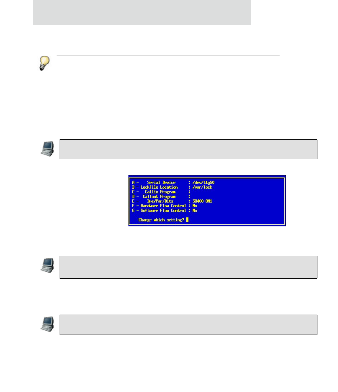
To configure minicom, start it as root by entering:
Go to “Serial port setup” and change the values to your environment.
Seyon
22
Figure 3-4: Minicom settings
Next time start minicom as a standard user with:
$ minicom
Start Seyon as a standard user by entering:
$ seyon -modems /dev/ttyS0
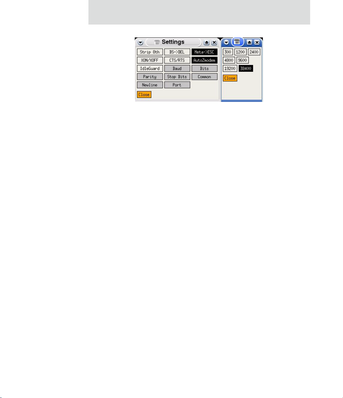
Go to “Seyon Command” window and press “Set”. In the “Settings” window you can
adjust the settings.
LxNETES User’s Guide
Page 23
Getting Started
Figure 3-2: Seyon Settings
Step 4: Connect power
Connect the included power supply to the development board. After power-on, the LEDs
on the board will light up and 2-4 seconds later the system will print boot messages on the
console. After 20-25 seconds, the boot load er has unpacked and launc hed the pre-i nstalled
Linux kernel from the built-in Flash memory.
You will see output on the terminal client similar to the output below.
23
Page 24

Introduction
U-Boot 1.1.3
U-Boot code: 20F00000 -> 20F1529C BSS: -> 20F19A80
RAM Configuration:
Bank #0: 20000000 32 MB
AM29LV128M (16MB)
Flash: 16 MB
In: serial
Out: serial
Err: serial
Hit any key to stop autoboot: 0
## Booting image at 20100000 ...
Image Name: Linux-2.6.12
Created: 2005-06-17 11:29:13 UTC
Image Type: ARM Linux Kernel Image (uncompressed)
Data Size: 2478816 Bytes = 2.4 MB
Load Address: 20008000
Entry Point: 20008000
Verifying Checksum ... OK
OK
Starting kernel ...
Linux version 2.6.12 (root@lxnetes) (gcc driver version 3.4.4 executing gcc version 3.4.4
CPU: ARM920Tid(wb) [41129200] revision 0 (ARMv4T)
CPU0: D VIVT write-back cache
CPU0: I cache: 16384 bytes, associativity 64, 32 byte lines, 8 sets
CPU0: D cache: 16384 bytes, associativity 64, 32 byte lines, 8 sets
Machine: ATMEL AT91RM9200
Memory policy: ECC disabled, Data cache writeback
...
...
...
BusyBox v1.00 Built-in shell (ash)
Enter 'help' for a list of built-in commands.
24
After Linux started successfully, you can enter commands such as "ls", "cd", or "cat"on
the shell.
Step 5: Test Ethernet configuration
The target uses a default IP address on the 192.168.42.x network. We recommend
configuring a network separate from your company network which is dedicated to the
LxNETES development. You can do this by adding and conf iguring a n additional network
card to use an IP address from the 192.168.42.0 subnet, e.g. 192.168.42.1.
LxNETES User’s Guide
Page 25

Getting Started
The target network parameters can be changed in U-Boot using the "setenv" command.
You can see the IP address of the target by issuing this command:
# ifconfig eth0
inet addr:192.168.42.10 Bcast:192.168.42.255 Mask:255.255.255.0
UP BROADCAST RUNNING MULTICAST MTU:1500 Metric:1
RX packets:3453 errors:0 dropped:0 overruns:0 frame:0
TX packets:62 errors:0 dropped:0 overruns:0 carrier:0
collisions:0 txqueuelen:1000
RX bytes:399740 (390.3 KiB) TX bytes:6726 (6.5 KiB)
Interrupt:24 Base address:0xc000
Link encap:Ethernet HWaddr 12:34:56:78:9A:BC
In this example, the target device has been given an IP addr ess o f 192.168.42.10. You can
test the proper functioning of the network by doi ng a ping to your host machine (Ctrl+ C to
stop).
# ping 192.168.42.1
PING 192.168.42.1 (192.168.42.1): 56 data bytes
64 bytes from 192.168.42.1: icmp_seq=0 ttl=64 time=10.6 ms
64 bytes from 192.168.42.1: icmp_seq=1 ttl=64 time=0.8 ms
64 bytes from 192.168.42.1: icmp_seq=2 ttl=64 time=0.8 ms
64 bytes from 192.168.42.1: icmp_seq=3 ttl=64 time=0.9 ms
--- 192.168.42.1 ping statistics --4 packets transmitted, 4 packets received, 0% packet loss
round-trip min/avg/max = 0.8/3.2/10.6 ms
Installing LxNETES
An installation script on the CD will do the installati on automatically. However, there are
some things the script cannot do such as setting up your DHCP or NFS server.
To install LxNETES, yo u must mount the CD. Enter the following:
$ mount /media/cdrom
25
Page 26

Guided Installation
The mount point of the CD drive depends on your distribution. SuSE e.g.
uses "/mnt/cdrom " as t h e de faul t moun t poi nt. Chec k yo ur "/ etc/ fs tab" or ask
your Administrator to do this for you.
Guided Installation
After mounting the CD you are ready to run the installer. Use the following commands to
start (depending on your distribution's mount point):
$ /media/cdrom/install.sh
If the script detects a Perl/ Tk installation, a graphical installer will start. If it does not
detect that Perl/Tk is installed, the installer will run on the console.
26
Select the directory where LxNETES should be installed. Click "Select" or type in the
path. If the directory doesn't exist, the installer will create it for you.
If you plan to be the only developer on your system it is a good idea to install LxNETES
to your home-directory. Otherwise you should use a global directory like "/usr/local".
Write to directories lik e "/usr /l ocal" by st art ing t he inst al le r as root ..
After selecting the installation, click "INSTALL". If an error accurs (e.g. no permissions
to write to the directory) the progress bar will turn red and an error message will appear.
If your system isn't able to run the graphical installer, a shell-installer will run.
The Installer will ask for the directory LxNETES should be installed.
LxNETES User’s Guide
Page 27

Manual Installation
Instead of using the installation script you can do the installation manually. Just copy the
directory "LxNETES" on the CDROM to a directory on your host PC.
Getting Started
27
Page 28

Manual Installation
28
LxNETES User’s Guide
Page 29

Building the First Project
CHAPTER 4
Building the Default Project
Until now you have worked with the pre-loaded, default kernel image on the target. The
next step is to rebuild it on your development host PC to familiarize yourself with the
build process.
Step 1: Run configure
Start a new shell and change in to your LxNETES inst allation directory.
Building the First Project
Create a new directory underneath and change to that directory.
Then execute configure for your platform to configure your project.
Example:
~$ cd $HOME/LxNETES-3.2
~/LxNETES-3.2$ mkdir build
~/LxNETES-3.2$ cd build
~/LxNETES-3.2/build$ ../configure
checking whether make sets $(MAKE)... yes
...
This configures your project for the default platform. If you want to configure another
platform, you have to specify it as a parameter to the configure script, for example
~/LxNETES-3.2/build$ ../configure --enable-platform=cc9p9750dev
checking whether make sets $(MAKE)... yes
...
The names for available platform:
ConnectCore 9P 9360: cc9p9360dev
29
Page 30

Building the Default Project
ConnectCore 9P 9750: cc9p9750dev
Please check if the script used the correct platform and detected the right directory to
install the kernel and the nfsroot directory. If you used the suggested paths in the setup of
the TFTPD and NFS server, the output of configure should contain:
checking which directory to install bootfiles to... /tftpboot
checking which directory to install nfsroot to... /exports
If configure returns an error, you can provide the correct paths to use:
--enable-exportdir=/path/to/exportdir
--enable-tftpbootdir=/path/to/tftpbootdir
Step 2: Run make
After configure finished successfully, run make:
~/LxNETES-3.2/build$ make
SHIPPED linux/.config
MAKE uImage
...
30
This will build your first kernel image.
Step 3: Run make install
If the configure scri pt was able to de tec t the di rector ies for exporti ng a r oot file system via
TFTP and NFS serving, add install to the make command to cop y the output files fr om the
build process to the appropriate locations.
~/LxNETES-3.2/build$ make install
...
You need write permissions in the corresponding directories.
LxNETES User’s Guide
Page 31

Application Development
CHAPTER 5
Writing applications
The user applications are stored in subdirectory apps/ of the project folder.
The template projec t includes several demo applications for use as te mplates to begin
developing your own programs. They will automatically build and copy to the folder
“/usr/bin/” of the target when building the system.
Adding your own applications
Application Development
To add a new application, run the script bin/add_app with the name of the new
application as first parameter.
Example:
~/LxNETES-3.2/build_custom$ bin/add_app customapp
This command creates a sample application named ‘customapp’ in the folder apps/
customapp in the source directory. Edit the file apps/customapp/customapp.c to insert
your application code.
To use more than one source file, just create the source files and modify Makefile.in to
include the files in the build process.
On the next call to make install, the application is added to your root file system.
31
Page 32

Writing applications
Using C++
A sample C++ applicatio n “hello_world” is included in “apps/misc/src/hello_world”.
You can use this sample application as a template to develop your own C++ applications.
Just use add_app as above and adapt the Makefile.in according to hello_world_cpp/
Makefile.in
Included example applications
There are several applications included in the project template with full source code:
display
This is a simple application that demonstrates the usage of the Common Gateway
Interface (CGI) to communicate data between the embedded web server (BOA) and a
target’s application.
Open a web browser in your development PC and type the IP address of the target in the
address box to access the embedded web page of the target.
32
You may enter any filename on the text box and click the Display button. The filename
will be given to the application which will send the contents of the file to your browser:
LxNETES User’s Guide
Page 33

Application Development
Table 6-3: /proc/cpuinfo contents
33
Page 34

Debugging applications
Debugging applications
The purpose of a debugg er i s to a llow you to see what i s going on hi s own pr ograms whi le
they execute. For that purpose the GDB debugger is used by means of the gdbserver
application that runs on the target side and communicates with the host computer. This
communication can happen on the serial port or through Ethernet (the latter is preferred
for being much faster).
The use of the GDB debugger is out of the scope of this manual. You can get more
information about it in the standard GDB man pages.
In order to debug an application it has to be rebuilt with debug information. To do that,
enter the target binary build directory (e.g. "apps/mem") and rebuild the application with
the following command:
~/LxNETES3.2$ rm apps/mem/*.o apps/mem/mem
~/LxNETES3.2$ make apps DEBUG=1 install
A binary mem will be created and copied to the rootfs. Restart the target with the new
rootfs.
34
Run the debug server on the target with the following commands:
# gdbserver localhost:2001 /usr/bin/mem
Process /mem created; pid = 39
Listening on port 2001
Remote debugging from host 192.168.42.1
->
Port number 2001 was selected randomly.
Now start the debug client on the host and connect to the target with
~/LxNETES3.2$ ../bin/arm-linux-gdb mem
GNU gdb 6.3
Copyright 2004 Free Software Foundation, Inc.
GDB is free software, covered by the GNU General Public License, and you are
welcome to change it and/or distribute copies of it under certain conditions.
Type "show copying" to see the conditions.
There is absolutely no warranty for GDB. Type "show warranty" for details.
This GDB was configured as "--host=i386-pc-linux-gnu --target=arm-linuxuclibc"
...
(gdb)
LxNETES User’s Guide
Page 35

Application Development
In the debug interface type
$ (gdb) set architecture ARCHITECTURE
$ (gdb) set solib-absolute-prefix <INSTALL_DIR>
$ (gdb) target remote TARGET.IP:2001
The supported architectures can be displayed with the following command:
$ (gdb) set architecture
Requires an argument. Valid arguments are arm, armv2, armv2a, armv3,
armv3m, armv4, armv4t, armv5, armv5t, armv5te, xscale, ep9312, iwmmxt,
auto.
Choose the right architecture for your target.
Valid
Argument
CC9C
CCXP270
UNC90
A9M2410
A9M2440
CC9P9360/9750
armv4 x x
armv5te x x
xscale x
Type "c" for continue.
You can now debug your application. Alternatively, you may try an external graphical
debugger like "ddd" or use "arm-linux-gdbtui" on the command line instead of
"arm-linux-gdb".
When debugging with the BDI2000:
On the A9M9750DEV development board, set dip-switch S4-1 and S4-3 to "on"
35
Page 36

Debugging applications
Included pre-built applications
The sources for the included applications can be found in the software folder on the
LxNETES CD.
Shell applications: busybox
The “busybox” includes all standard shell applications like “cat”, “chmod”, “echo”,
“mount”, “sh” and some more. They are linked into one static application to save flash
memory, at the cost of a larger RAM footprint for each application, so this is not
recommended for daemons. LxNETES has stripped off the less important applications in
order to obtain a small busybox binary.
Telnet daemon: utelnetd
Utelnetd is a small telnet daemon. It is launched by “init”. For login use the Telnet on our
host computer to connect to the target.
You don’t need to provide username or password.
Web server: Boa
Boa is a small single-tasking HTTP server. The configuration file “boa.conf” is l ocated i n
the “/etc/boa/” directory on the target. It can be modified on the host system. There it is
located in “base_rootfs/etc/boa/” in the source directory.
Debug server: gdbserver
With gdbserver it is possible to debug on a remote machine while the d ebug ger it sel f r uns
on the host system.
36
LxNETES User’s Guide
Page 37

Nano-X/microwindows
Nano-X makes it possible to write applications using the fr amebuffer with an API similar
to Xlib. There are two demo applications. To use either you must start with the nano-X
server.
# nano-X &
and then the application.
# nanox_bar &
On targets with small flash, nano-X is disabled by default. You may pass
“--enable nano-X” to configure, despite the flash size, but you risk overwriting the
rootfs on the target.
For further details see http://www.microwindows.org/
Application Development
Embedded Qt
# qthello -qws
On targets with small flash, Qt is disabled by default. You may pass “--enable qt” to
configure, despite the flash size, but you risk overwriting the rootfs on the target.
Embedded Qt is a small variant from the Troll Tech Cross Platform GUI toolkit. A demo
is included. To start the demo enter the following:
For further information see http://www.trolltech.com/products/qt3/embedded/
37
Page 38

Useful applications
Useful applications
mem
With this application you can read and write the contents of the SDRAM.
All the options of this tool are accessible throu gh a command line . Just type an 'h ' to list a ll
the available commands:
# mem
-> h
c <addr> [<len>]: Display char at
w <addr> [<len>]: Display word at
i <addr> [<len>]: Display int at
s <addr>: Display string at
B <addr> <val> [<len>]: Write byteval at addr
W <addr> <val> [<len>]: Write wordval at addr
I <addr> <val> [<len>]: Write intval at addr
/ <addr> <txt> [<len>]: Search string at
h :Display this help
q :Quit
-> b 0x31000000 32
0x31000000: 0xff 0xff 0xff 0xbf 0xfd 0x7d 0xbf 0xcd 0xf9 0xfb 0xfe 0xfb 0xff
0xfb 0xff 0xfb
0x31000010: 0xbf 0xd7 0xf5 0xff 0xff 0xff 0xf7 0xff 0xff 0xff 0xee 0xff 0x7f
0x7f 0xff 0xe7
->
38
LxNETES User’s Guide
Page 39

Kernel Development
CHAPTER 6
Writing kernel modules
What is a kernel module?
Modules are pieces of code that can be loaded and unloaded into the kernel upon demand. They are useful
because they extend the functionality of the kernel without the need to reboot the system.
A typical kernel module is the device driver, which allows the kernel to access hardware connected to the
system. Witho ut modules, yo u would ha ve to build subs tantial kernels and add n ew functio nality direc tly
into the kernel image. Besides having exte nsiv e kernels, yo u wou ld be requ ire d to reb uild and re bo ot the
kernel for every new functionality.
Kernel Development
Writing your own kernel modul es
Some kernel modules are inclu ded as examples. They can be found in the modules/ subdirector y of the
project folder. Each kernel module must be stored in a differen t folder.
The easiest way to create your own kernel module is to clone one of the existing modules:
~/LxNETES3.2$ cd modules
~/LxNETES3.2/modules$ cp -r minimal my_kmodule
~/LxNETES3.2/modules$ cd my_kmodule
Add your source files
Add the sources for your kernel module directly to the new folder you’ve just created, and remove the
original source files of the folder th at you cloned.
39
Page 40

Writing kernel modules
Add the module to the build environment
You have to edit "my_kmodule/Makefile.in" so that the build environment knows what files to build.
T o inc lu de the m for the target build, append them to obj-m like "obj-m += my_module.o". The modules
must be named like their C-source files. Usable object modules will have the extension ".ko".
# Add your kernel modules here
obj-m += my_module.o
Then you have to add the module t o the list of available modu les. Edit the configure.ac and modify the
line adding the module minimal to add your module to the list.
LXNETES_KMODULES([minimal my_kmodule])
Building and loading of kernel modules
For building the new kernel module, j ust rebuild your project by issuing make i n the build director y.
If you reboot your target with the newly created rootfs (or if you mount your rootfs via
modules can be loaded in the target with "modprobe my_kmodule"
There is an example "minimal.c" for the most minimalist kernel module. Try it with
"modprobe/minimal"
nfs), The
# modprobe /minimal
Minimal driver $Revision: 1.1 $ loaded
# cat /proc/modules
minimal 1536 0 - Live 0xbf000000
# rmmod minimal
Minimal driver unloaded
# cat /proc/modules
Included Kernel modules
minimal
This is a minimalist kernel module which actually does nothing. It is only a module to test the
functionality of the load and unlo ad functio n s of the ke rne l.
40
LxNETES User’s Guide
Page 41

Advanced Topics
CHAPTER 7
Modifying the default project
The following information is the default kernel configuration for LxNETES:
serial baudrate 38400 bps
Ethernet enabled
uses devfs per default
The default configuration is made up of 2 layers:
Advanced Topics
Kernel command line para meters: set by U-Boot
Kernel configuration: lowest priority
The kernel command line parameters can overwrite some configurations. However, if
there is no boot loader , th e only way the k ernel command line paramet ers can be ent ered is
by compiling them into the kernel.
To change the kernel configuration to the needs of your target system, enter the following
commands from the project build directory:
$ make xconfig
The menu-driven kernel configuration tool “xconfig” is started. Here you can do your
changes.
Figure 8-1: Kernel configuration
41
Page 42

Modifying the default project
42
Once you have configured the kernel to your system needs, save the configuration and
exit. To rebuild the kernel use one of the build commands seen before.
$ make (to build the entire project)
$ make uImage(to build only the linux kernel)
LxNETES User’s Guide
Page 43

Building a custom project
To create a custom project, that is a project for your custom hardware, first configure the
default project. Foll ow the step s described in "Buildi ng the Defaul t Proj ect" up t o running
configure. Then run:
$ ~/LxNETES-3.2/build$ bin/add_platform –b cc9p9360dev custom
$ checking whether make sets $(MAKE)... yes
$ ...
Advanced Topics
In this example, ConnectCor e 9P 9360 de v module (
cc9p9360dev)was used as the template
project. Substitute the platform that is most similar to the platform you intend to create.
Then create a new build directory and configure for your custom platform:
~/LxNETES-3.2/build$ cd ..
~/LxNETES-3.2$ mkdir build_custom
~/LxNETES-3.2$ cd build_custom
~/LxNETES-3.2/build_custom$ ../configure –-enable-platform=custom
...
Check the detected settings are correct in the new run of configure.
Now you can reconfigure your custom kernel by running:
~/LxNETES-3.2/build_custom$ make xconfig
You need QT installed to run make xconfig (Debian package libqt3-mt-dev). If you don't
have it, use menuconfig (requiring ncurses, Debian package libncurses5-dev).
You have to run make xconfig in the build directory. Running in other directories (e.g.
~/LxNETES-3.2/build_custom, ~/LxNETES-3.2/build_custom/linux, or ~/LxNETES-3.2/
linux) will fail.
You can build and install the project for the default platform after the previous steps are
complete.
43
Page 44

Boot process
Boot process
Introduction
This chapter describes the boot process of U-Boot and Linux.
A boot loader is a small piece of software that executes soon after powering up a
computer. On a desktop PC it resides on the master boot record (MBR) of the hard drive
and is executed after the PC BIOS performs various system init ializations. The boot
loader then passes system information to the kernel and then executes the kernel. For
instance, the boot loader te lls the kernel which hard d rive partition to moun t as root.
In an embedded system the role of the boot loader is more complicated since these
systems do not have a BIOS to perform the initial system configuration. The low level
initialization of the micr oprocessor , memory control lers and other board speci fic hardware
varies from board to board and CPU to CPU. These initializations must be performed
before a Linux kernel image can execute.
At a minimum, a boot loader for an embedded system performs the following functions:
Initialize the hardware, especially the memory controller.
U-Boot
44
Provides boot parameters for the operating system image.
Starts the operating system image.
Additionally, most boot loaders also provide convenient features that simplify
development and update of the firmware:
Reading and writing arbitrary me mory locations.
Uploading new binary images to the board's RAM via a serial line or Ethernet
Copying binary images from RAM to Flash memory.
After power-up or reset the processor loads the U-Boot boot loader. This is performed in
different steps and depends on the target.
LxNETES User’s Guide
Page 45

ConnectCore 9P 9360/9750
On the ConnectCore 9P 9360 and ConnectCore 9P 9750 modules, the SPI boot loader is
loaded from the SPI EEPROM which initializes the RAM. Then additional code (~1kB) is
loaded into RAM (address 0x0). This code loads U-Boot from NAND flash and executes
it.
In the next step, U-Boot configures the serial console, the Ethernet interface and t he Flash
memory and loads the setti ngs stored as environment va riab le s in the nonvolatile memory.
Then, it waits some seconds (programmable) before it loads and starts the operating
system image. You can stop the auto-boot process by sending a character to the serial port
(pressing a key on the serial console connected to the target). If stopped, U-Boot displays
a command line console similar to this:
U-Boot 1.1.3 (Sep 15 2005 - 17:02:40) FS.1
CC9P9360 module on A9M9750DEV_1 development board
CPLD Version: 2.1
FPGA Version: 2.1
U-Boot code: 00080000 -> 000A6020 BSS: -> 000B8A00
RAM Configuration:
Bank # 0: 00000000 32 MB
NAND: 32 MB
In: serial
Out: serial
Err: serial
Hit any key to stop autoboot: 0
CC9P9360 #
Advanced Topics
45
Page 46

Linux boot methods
Linux boot methods
Linux is booted by U-Boot in one of the following ways:
TFTP/NFS
Flash memory
USB storage device (e.g. an USB memory stick)
The following information describes each boot method.
TFTP/NFS
With this method, the Linux kernel is downloaded through Ethernet via TFTP protocol
from the server's TFTP folder.
Use the "tftp" command from the U-Boot command line to copy a kernel imag e from your
TFTP server to the target's RAM. Then use "bootm" to execute it.
# setenv bootargs console=...
ip=$(ipaddr):$(serverip)::$(netmask):2440:eth0:off root=nfs
nfsroot=$(serverip):$(npath)
# tftp <load_addr> <kernel_image>
# bootm <load_addr>
A faster way to do this is to use the "boot_net" macro, which loads a kernel image from your
TFTP server to the target's RAM and then connect to a root file system via NFS.
NAND-Flash
# setenv bootargs console=...
# nand read.jffs2s <load_addr> <start flash> <kernel_image_size>
# bootm <load_addr>
46
This method will load the Linux kernel and the root file system from NAND Flash.
Use the "nand read.jffs2" command to load the kernel from the NAND flash.
After copying the kernel image from NAND to flash you can run it with "bootm".
ip=$(ipaddr):$(serverip)::$(netmask):2440:eth0:off root=/dev/mtdblock2
rootfstype=jffs2
LxNETES User’s Guide
Page 47

A faster way to do this is to use the "boot_flash" macro.
NOR Flash
# setenv bootargs console=...
# cp.b <start flash> <load_addr> <kernel_image_size>
# bootm <load_addr>
A faster way to do this is to use the "boot_flash" macro.
USB
Advanced Topics
Use the following commands if you have NOR Flash (similar to booting from NAND).
ip=$(ipaddr):$(serverip)::$(netmask):2440:eth0:off root=/dev/mtdblock2
rootfstype=jffs2
It is possible to load a kernel image from a USB storage device. Copy the kernal to the
FAT partition of the USB device.
Copy the kernal to the USB stick.
The commands update_kernel_usb and guu are provided.
Enter the following to copy the kernel from th e USB stick to the memory.
# run guu
The image can now be executed with the bootm command.
There is also a macro for boot_usb which does both steps. It is run boot_usb.
# run boot_usb
47
Page 48

Linux boot process
Update the kenel from the USB stick to the memory and write it to flash memory.
# run update_kernel_usb
Linux boot process
The command “bootm” uncompress the kernel and runs the function start_kernel(). Once
the kernel is started, several options are given to the kernel: machine type, command line
and ATAG list. The kernel itself does some basic initialization;
MMU
Machine Type
Interrupt Handler
Timer
Loading drivers
48
LxNETES User’s Guide
Page 49

Advanced Topics
Uncompressing
Linux.......................................................................
done, booting the kernel.
Linux version 2.6.12.5-fs.1 (jdietsch@onyx.fsforth.de) (gcc version 3.4.4) #1
Mon Sep 19 17:30:44 CEST 2005
CPU: ARM926EJ-Sid(wb) [41069264] revision 4 (ARMv5TEJ)
CPU0: D VIVT write-back cache
CPU0: I cache: 8192 bytes, associativity 4, 32 byte lines, 64 sets
CPU0: D cache: 4096 bytes, associativity 4, 32 byte lines, 32 sets
Machine: A9M9360
Memory policy: ECC disabled, Data cache writeback
NS9360 Rev. 0, running at 176 MHz
Built 1 zonelists
Kernel command line: console=ttyS0,38400
ip=192.168.42.10:192.168.42.1:192.168.42.1:255.255.255.0:a9m9360:eth0:off
nfsroot=192.168.42.1:/exports/nfsroot-cc9p9360dev root=nfs
PID hash table entries: 256 (order: 8, 4096 bytes)
Console: colour dummy device 80x30
Dentry cache hash table entries: 8192 (order: 3, 32768 bytes)
Inode-cache hash table entries: 4096 (order: 2, 16384 bytes)
Memory: 32MB = 32MB total
Memory: 29756KB available (2097K code, 387K data, 104K init)
Mount-cache hash table entries: 512
CPU: Testing write buffer coherency: ok
NET: Registered protocol family 16
SCSI subsystem initialized
usbcore: registered new driver usbfs
Freeing init memory: 104K
Mounting kernel filesystems: proc sysfs /dev/pts.
Starting syslog daemon: syslogd.
Starting boa webserver: boa.
Starting telnet server: utelnetd.
BusyBox v1.00 (2005.09.05-08:11+0000) Built-in shell (ash)
Enter 'help' for a list of built-in commands.
/ #
49
Page 50

Linux boot process
If a wrong command line parameter for "console=" i s used, nothing wi ll be displaye d after
"done, booting the kernel". The system may continue to boot. You may connect to the
target by Telnet after telnetd is conf igured .
After finishing the initialization, the filesyst ems are mounted and the process "/sbin/init"
is started with process ID 0. Init runs all applications stated in "/etc/inittab", e.g. "/etc/
init.d/rcS", the various daemons like telnetd and shells on the serial consoles.
Passing arguments to the kernel
Depending on the kernel settings, add itional command li ne argument s may be given to the
kernel. This can be modified by editing the std_bootarg environment variable. For
example, to enable a console on a different serial port than the standard one when Linux
boots, add 'console=ttyS1':
# setenv std_bootarg console=ttyS1
# saveenv
Automating the image download
It is also possible to automate the bo ot process t o al ways boot by n etwo rk when t he t ar get
is reset. Adjust the environm e nt variable "bootcmd" to contain the " run boottftp” script
seen before:
# setenv bootcmd run boot_net
# saveenv
Don't forget "saveenv" to store your settings.
If you want to store a script with several commands into a variable, separate each
command with a semicolon prefixed with a "\" to prevent ending the setenv
command itself. (i.e. setenv MyCommand cmd1\;cmd2\;cmd3)
Updating the Flash memory
This chapter describes how you can update the U-Boot boot loader, the Linux kernel, and
the root file system in the Flash memory of the module.
It is strongly recommended that you test your images before updating the Flash memory
by downloading them over Ethernet using TFTP.
50
LxNETES User’s Guide
Page 51

Updating a running system (the easy way)
On a running system, that is a system able to start the boot loader, U-Boot contains predefined macros that can update the on-module flash memory.
If the boot loader is corrupted, you have to first use a debugger to restore
the boot loader which then can be used to restore the remaining images.
Power up (or reset) the target. After 2-4 seconds, the boot loader messages appear on the
serial port. Hit any key to interrupt the auto-boot process. You can break into the U-Boot
command line interface by pressing any key.
There are 3 main flash partitions: U-Boot, ker nel ima ge, and a root fil e system. To update
a partition using a TFTP se rver, run one or more of t he followin g macros fr om the U-Boot
prompt:
# run update_uboot_tftp
# run update_kernel_tftp
# run update_rootfs_tftp
Advanced Topics
You can also copy the images onto a vfat formatted usb-stick, connect it to the target, and
run one or more of these macros from the U-Boot prompt:
# run update_uboot_usb
# run update_kernel_usb
# run update_rootfs_usb
Updating a running system manually
Advanced users may want to have more control over the flash update process. In this case,
use the steps below to update an image on a running system. It is presumed you are using
the memory layout as described in Appendix A of this document.
.
For more information about the use of U-Boot commands, refer Appendix A or
the related documentation in Appendix B.
51
Page 52

Linux boot process
Step 1: Download the new image file to RAM
The first step is to download the image into RAM. Specify the start address, the end
address, and the size of the image in RAM, for example:
# mw.l <start address in RAM> <end address in RAM> <image size>
# tftp <start address> <image name>
# Filename <image name>.
# Load address: <memory address>
Loading:
#####################################################
#####################################################
########################################
# done
Step 2: Erase the Flash partition
The second step is to erase the Flash partit ion sectors. Specify the start address and the end
address of the range to be deleted.
For modules with NAND flash, use this command:
52
# nand erase <start address in Flash> <size>
For modules with NOR flash, use this command:
# erase <start address in Flash> <end address in Flash>
Step 3: Write the image to Flash
After the image is downloaded into RAM and the flash erased, the new image can be
copied into Flash.
For modules with NAND flash, use this command:
# nand write.jffs2 <start address in RAM> <start address in Flash> <image
size>
LxNETES User’s Guide
Page 53

For modules with NOR flash, use this command:
# cp.b <start address in RAM> <start address in Flash> <image size>
ConnectCore 9P 9360/9750
The following commands are to update the U-Boot loader, Kernel image, and Root file
system.
U-Boot
To update the U-Boot boot loader, type:
mw.l 100000 ffffffff 10000
tftp 100000 <u-boot_image>
nand erase 0 40000
nand write.jffs2 100000 0 u-boot_image_size
reset
Advanced Topics
Kernel
To update the Linux kernel image, type:
tftp 100000 <kernel_image>
nand erase 40000 2C0000
nand write.jffs2 100000 40000 kernel_image_size
Root File System
To update the root file system, type:
tftp 100000 <rootfs_image>
nand erase 300000 (Size of flash – 3MB)
nand write.jffs2 100000 300000 rootfs_image_size
53
Page 54

Updating a corrupted system using a debugger
Updating a corrupted system using a debugger
ConnectCore 9P 9360/9750
If the Flash memory has become corrupted and the system cannot boot anymore, then the
Flash memory must be re-programmed using the JTAG interface and the JTAG-Booster.
Connect the JTAG-Boosters 8-pin connector to the development board (JTAG X12). The
two black cables point to pin 1.
Set DIP-switch S4-1 to "on" and S4-2 to S4-8 to "off".
Copy the JTAG tools from the LxNETES-3.2 CD to the host system. A detailed manual
how to setup the JTAG-Booster can be found on the LxNETES-3.2 CD, hardware/jtag.
On a Linux system use a tool like dosemu to get the JTAG tools running.
Once you have installed the JTAG tools on your host computer, copy the U-Boot image
that you want to program into the Flash memory, to the same directory and execute the
batch file to flash U-Boot.
After a successful programming of U-Boot, the kernel and the Root File System can be
updated (if they were corrupted, too).
54
LxNETES User’s Guide
Page 55

NFSROOT
Root File System Types
Root File System Types
CHAPTER 8
The following describes the different possibilities which can be used as root file system.
The type of rootfs must be passed as an argument to kernel by means of the bootargs
environment variable of U-Boot.
The rootfs may be in a different computer on the network and not within the target. This
can be useful if, for example, a RAM disk is too small to include all the necessary files, or
allow rapid turnaround during testing and development.
An NFS root allows quick kernel downloads, helps ensure file system integrity (since the
server is basically impervious to crashes by the client), and provides virtually infinite
storage.
During development it feel free to use an NFS directory as root file system. This avoids
unnecessary flash erases, which on a power failure will result in the need to re-program
the kernel into flash. It also increases the lifetime of the module because the flash has a
limited number of erase cycles. Initialization scripts may be quickly modified since a
failure will not result in an unusable system. Initialization scripts can be fixed on the host
then reset the target.
The root file system can be installed to "/exports/BOOTDIR" issuing this command in the
project directory
$ make install-nfsroot
To test the new image run the following command at the U-Boot prompt in your target:
55
Page 56

# run boot_net
This script does three steps (that you can also do manually):
Step 1: Set bootargs to be passed to the kernel
The environmental variabl e boo targs must be updated to tel l Li nux t hat t he r oo tfs i s taken
via NFS. To manually do this enter the following commands (it is supposed that the
network variables serverip and nfspath have been already set). The values for ip and
console have to be filled depending on the platform.
# setenv bootargs nfsroot=$(serverip):$(nfspath) root=nfs ip=... console=...
# saveenv
Step 2: Download the kernel to RAM via TFTP
The following commands download the “/tftpboot/uImage-unc90” image to RAM
memory
# tftp 20100000 uImage-unc90dev
# bootm 20100000
Remember that you must have the U-Boot network environment variables properly
configured (ipaddr, serverip,...).
56
Step 3: Launch the kernel from RAM
Now that the kernel image has been downloaded to RAM, we can execute Linux with th e
following command
LxNETES User’s Guide
Page 57

JFFS2
Root File System Types
JFFS is a log-structured journaling flash file system which was designed to be used on
Flash devices in embedded systems. It was ori ginall y develope d for the 2.0 k ernel b y Axis
Communications. JFFS2 is an improved ve rsion of JFFS which incl udes compressio n and
improved read/write access.
Find more about JFFS2 at http://sourceware.org/jffs2
NAND chips are not guaranteed to be error free and most chips have bad blocks.
Therefore, U-Boot as well as Lin ux has to know h ow to handl e these bad blocks. Both use
JFFS2 for this purpose.
U-boot provides the commands "nand read.jffs2.s" and "nand write.jffs2". Both
commands are skipping bad blocks. Therefore, there must be some space left for reserve
blocks. In U-Boot you can run the "nand bad" command for a summary of known bad
blocks on the flash device.
In Linux a JFFS2 driver for NOR and NAND chips can be used.
If a jffs2 image should be copied to a partition it must be ensured that the image was
created with the correct erase size of the used chip. Otherwise Linux will print error
messages on the screen.
To reduce memory allocation Linux uses a virtual erase size if the physical erase size of
the chip is to small. A message li ke the one below may be printed on the console
jffs2: Erase block size too small (XXKiB. Using virtual blocks size(XXKiB)
instead
Another message which could be printed on the console is
Empty flash at 0xXXXXXXXX ends at 0xXXXXXXXX
This message doesn't indic ate a proble m. Inst ead, it i s pri nted if a bloc k of da ta is partial ly
written. These messages will disappear when the garbage collection restructures the
remaining space
57
Page 58

jffs2_get_inode_nodes(): Data CRC failed on node at 0xXX XXXXXX: Read
0xXXXXXXXX, calculated 0xXXXXXXXX
The message above is printed if the file system was not cleanly unmounted. The system
should not be powered off before all partitions are unmounted. After a clean unmount, the
message should disappear.
Step 1: Set bootargs to be passed to the kernel
The environmental variabl e boo targs must be updated to tel l Li nux t hat t he r oo tfs i s taken
from Flash and it is stored in JFFS2 file system. Enter the fo llowing commands to
manually initate these commands:
# setenv bootargs root=/dev/mtdblock3 rw rootfstype=jffs2 ip=... console=...
# saveenv
Step 2: Copy the kernel to RAM
Depending on the flash type of your platform, use for NOR flash the following command
to copy the kernel from Flash to RAM memory:
# cp.b <startaddr> <loadaddr> <image_size>
# nand read.jffs2s <loadaddr> <startaddr> <image_size>
# bootm <loadaddr>
58
For NAND flash use the following command:
Step 3: Launch the kernel from RAM
Now that the kernel image has been copied to RAM, we can execute Linux with the
following command:
LxNETES User’s Guide
Page 59

Root File System Types
You should use a separate data partition for your data which is frequently updated so
your rootfs does not get corrupted.
59
Page 60

60
LxNETES User’s Guide
Page 61

Compact Flash
Interfaces & Devices
Interfaces & Devices
CHAPTER 9
The following interfaces and devices are supported in the current LxNETES version:
a9m2410 a9m2440 cc9c cc9p9360 cc9p9750 ccxp270 unc90
only available
X X X X X
on the
UNCBASCF
base board
Ethernet
I2C Interface
LCD
PCI
RTC
SD card
Serial
SPI
Touch screen
USB Host
Serial interface
X X X X X X X
X X X X X X X
X X X X X
n/a n/a n/a n/a X n/a n/a
X X X X X X
X X n/a
X X X X X X X
X X X X
X X X X
X X X X X X X
Refer to the docume ntation that came with the development b oard for the location of the
interfaces on the board as well as any board configuration required to enable these
interfaces.
A driver for the serial interfaces is included and enabled in the default kernel
configuration. Devices can be accessed via /dev/ttyS<n>.
61
Page 62

USB host interface
A USB host driver is included and enabled in the default ker nel conf i gurat i on. To operate
multiple USB devices simultaneously, connect a USB hub to the USB host port.
A memory stick can be mounted as followed
# lxmount usb
# ls -l /media/usbdisk
I2C interface
A driver for the I2C interface is included and enabled in the default kernel configuration.
Devices attached to the I2C interface can be accessed via /sys/bus/i2c/device/<your
device>.
SPI interface
A driver for the SPI interface is included and enabled in the default kernel configuration.
It can be accessed via /sys/bus/spi/device/<your device>.
LCD interface
A LCD frame buffer driver is included and enabled in the default Linux kernel
configuration.
Touch screen interface
CC9P9360/9750
A driver for the touch controller on the LCDMODARM development board, which is
connected via SPI, is included and enabled in the default Linux kernel configuration.
62
LxNETES User’s Guide
Page 63

Compact flash interface
CC9P6360/9750
A driver for the internal Compact Flash (CF) card interface is included and enabled in the
default kernel configuration.
A CF card can be mounted as follows
# lxmount cf
# ls -l /media/cf
SD card interface
A SD card can be mounted as follows:
# lxmount sd
# ls -l /media/sd
Interfaces & Devices
Real time clock (RTC)
A driver for the RTC, which is connected to the I2C interface, is included and enabled in
the default kernel configuration.
The system time and date is automatically set to the values of the RTC when the kernel
boots. This is done by calling /sbin/hwclock -s.
How to set the initial system date and time
Initially, the R TC doesn’ t have a correct time/date val ue, so establish t he correct time/date
on the Linux system using the date command. The parameters are given in the format
MMDDhhmmYYYY (month,day ,hour,minutes,year). For example, if the date is June, 3
2005, at 13:22 enter:
# date 060313222005
Fri Jun 3 13:22:00 UTC 2005
rd
63
Page 64

# hwclock
Fri Jun 3 13:22:44 UTC 2005 0.000000 seconds
PCI interface
The next step is to store this information into the RTC. Use the application hwclock:
Now you can reset or power off your target. The small battery on the development board
will keep the correct time/date values and are saved when you power up you r target again.
A driver for the PCI interface can be enabled in the kernel configuration. You can use
Mini-PCI cards with the Mini-PCI slot on the development board.
64
LxNETES User’s Guide
Page 65

•
Appendix A
•••••••••••••••••••••••••••••••••••••••••••••••••••••••
Related documentation
http://www.modarm9.com ModARM9 home page for forum, download area and FAQs
http://www.fsforth.de Manufacturer of UNC20, ModNET50, ModARM9
http://www.kernel.org Homepage of the Linux Kernel
http://u-boot.sourceforge.net Homepage of the U-Boot Loader
http://www.uclibc.org
http://www.abatron.ch Manufacturer of the BDI2000 for debugging via JTAG
http://www.samsung.com Manufacturer of S3C2410 processor
http://www.netsilicon.com Manufacturer of NS9750/ NS9360 processor
http://www.atmel.com Manufacturer of AT91RM9200 processor
Linux Device Drivers ISBN 0-596-00590-3
http://sourceware.org/jffs2 JFFS2 overview
http://sources.redhat . com/jffs2 Detailed Informat ion about JFFS2
http://www.gnu.org/software/gdb/
documentation
Homepage of the user library and user applications. Toolchain
is also created by uclibc's build flow
GDB debugger documentation
CD contents
The CD contains all the necessary software and documentation needed for LxNETES.
Note: The folders 'images', 'LxNETES' and 'hardware' contain their own readme.txt file
including additional information about the directory content.
65
Page 66

Related documentation
There following folders are on the CD:
Readme.txt
Briefly describes LxNETES and lists the CD contents.
RelNotes.txt
Contains the last release information.
install.sh
A script to install LxNETES on your host computer. For more information see chapter 4
(installation).
docs
The doc folder contains this User's Manual and additional documentation.
images
66
This folder contains pre-built images for your target platform. These images are already
programmed into the Flash memory on all modules shipped with a development kit.
The files in the imags folder are named according to the following scheme:
File Description
u-boot-<platform >.bin U-Boot boot loader image for <platform>
uImage-<platform> Linux kernel image fo r <platfor m>
rootfs-<platform> Root file system for <platform>
LxNETES User’s Guide
Page 67

ConnectCore 9P 9360 (CC9P9360)
File Description
u-boot-cc9p9360dev.bin U-Boot boot loader image for the ConnectCore 9P 9360 module on the
ConnectCore 9P development board.
uImage-cc9p9360dev.bin Linux kernel image for the ConnectCore 9P 9360 module on the ConnectCore
9P development board.
rootfs-cc9p9360dev.jffs2 Root file system for the ConnectCore 9P 9360 module.
ConnectCore 9P 9750 (CC9P9750)
File Description
u-boot-cc9p9750dev.bin
uImage-cc9p9750dev
rootfs-cc9p9750dev.jffs2 Root file system for the ConnectCore 9P 9750 module.
hardware
LxNETES
U-Boot boot loader image for ConnectCore 9P 9750 module on the
ConnectCore 9P development board (A9M9750DEV, P/N 376).
The Linux kernel image for the ConnectCore 9P 9750 module on the
ConnectCore 9P development board (A9M9750DEV).
This folder contains hardware specific content. The JTAG Booster software (if
supported by the target pla tform) is located here, hardware reference manuals
and (depending on your target platform) files for CPLD logic.
Please refer to the documentation in this directory for more information.
These files will be installed on the development host computer during the
installation process. This in cludes source code and the environment to build the
complete LxNETES distribution
setup
This folder contains file s needed to install LxNETES
67
Page 68

Memory layouts
upstream
U-Boot
Memory layouts
Flash memory layout
LxNETES is based on various open source projects. The original source code
from these projects is stored in this folder. The following source code is
included:
Linux
Buildroot
This folder contains the source code of U-Boot including all patches which are
necessary for the specific target.
The partitioning of the nonvolatile memory is described in this following table.
ConnectCore 9P 9360 / ConnectCore 9P 9750
Flash Start Address Size Partition Name mtdblock/
0x00000000 0x00040000 U-Boot 0
0x00040000 0x002C0000 Kernel 1
0x00300000 (Size of flash – 3MB) rootfs 2
SDRAM memory layout
The following tables describe some typical addresses in memory used by U-Boot and
Linux.
68
LxNETES User’s Guide
Page 69

ConnectCore 9P 9360 / ConnectCore 9P 9750
RAM Start
Address
RAM End
Address
Description Used by
0x00000000 0x00080000 U-Boot stack
0x00080000 0x000C0000 U-Boot
0x00100000
0x00108000
default load address in UBoot for Linux kernel
entry point of the
decompressed kernel
U-Boot0x00080000 TEXT_BASE
Linux
69
Page 70

Memory layouts
70
LxNETES User’s Guide
Page 71

•
Appendix B
•••••••••••••••••••••••••••••••••••••••••••••••••••••••
U-Boot command reference
This chapter gives an overview of commo n used U-Boot command s. Detailed inf ormation
can be found at:
http://www.denx.de/wiki/view/DULG/Manual?stickboard=tqm8xxl
T o get to t he U-Boot prompt press any key immedia tely aft er you have powe red the tar get
on or pressed reset. At the prompt type “help” or “?” to get an overview of the supported
commands.
71
Page 72

U-Boot command reference
# help
# ? - alias for 'help'
# autoscr - run script from memory
# base - print or set address offset
# bdinfo - print Board Info structure
# boot - boot default, i.e., run 'bootcmd'
# bootd - boot default, i.e., run 'bootcmd'
# bootelf - Boot from an ELF image in memory
# bootm - boot application image from memory
# bootp - boot image via network using BootP/TFTP protocol
# bootvx - Boot vxWorks from an ELF image
# cmp - memory compare
# coninfo - print console devices and information
# cp - memory copy
# crc32 - checksum calculation
# date - get/set/reset date & time
# echo - echo args to console
# eeprom - EEPROM sub-system
# fatinfo - print information about filesystem
# fatload - load binary file from a dos filesystem
# fatls - list files in a directory (default /)
# fsinfo - print information about filesystems
# fsload - load binary file from a filesystem image
# go - start application at address 'addr'
# help - print online help
# icrc32 - checksum calculation
# iloop - infinite loop on address range
# imd - i2c memory display
# iminfo - print header information for application image
# imls - list all images found in flash
# imm - i2c memory modify (auto-incrementing)
# imw - memory write (fill)
# inm - memory modify (constant address)
# iprobe - probe to discover valid I2C chip addresses
# itest - return true/false on integer compare
# loadb - load binary file over serial line (kermit mode)
# loads - load S-Record file over serial line
# loop - infinite loop on address range
# ls - list files in a directory (default /)
# md - memory display
# mm - memory modify (auto-incrementing)
# mtest - simple RAM test
# mw - memory write (fill)
# nand - NAND sub-system
# nboot - boot from NAND device
# nfs - boot image via network using NFS protocol
# nm - memory modify (constant address)
# ping - send ICMP ECHO_REQUEST to network host
# printenv- print environment variables
# rarpboot- boot image via network using RARP/TFTP protocol
# reset - Perform RESET of the CPU
# run - run commands in an environment variable
# saveenv - save environment variables to persistent storage
# setenv - set environment variables
# sleep - delay execution for some time
# tftpboot- boot image via network using TFTP protocol
# usb - USB sub-system
# usbboot - boot from USB device
# version - print monitor version
72
LxNETES User’s Guide
Page 73

Each of these commands has additional help available, which can be viewed by entering
help <command>.
All numeric values, which are needed for different commands, are interpreted as
HEX values. Entering 30100000 means 0x30100000.To speed up programming,
the real size of the image files can be used. In the commands above we have
used the maximum size of the partition instead of the actual size of the image
files (0x180000 words = 3 Mb)
The following table explains some of the more often used commands:
bootm ADDR ARG
boot, bootd boots image via running default bootcmd
nand bad prints a list of bad blocks on the current device
nand erase OFF SIZE erase SIZE bytes from OFF
nand erase clean
nand read ADDR OFF SIZE
nand read.jffs2s ADDR OFF SIZE
nand write ADDR OFF SIZE
nand write.jffs2 ADDR OFF SIZE
printenv prints the environment variables
saveenv stores the changed environment variables persistently
setenv VARIABLE VALUE
boots image from ADDR passing arguments ARG. ARG is the
address of the initrd image
erase entire NAND Flash
WARNING: after this command, U-Boot has to be reprogrammed
read SIZE bytes from OFF in NAND flash to ADDR. If there are
bad blocks the command stops with an error.
read SIZE bytes from OFF in NAND flash to ADDR. Bad blocks are
skipped.
write SIZE bytes from ADDR to OFF in NAND flash. If ther e are
bad blocks or writing fails the command stops with an error.
write SIZE bytes from ADDR to OFF in NAND flash. Bad blocks
are skipped.
sets the environment variable VARIABLE to the given value
VALUE. If a semicolon is used, to set different variables, it has to
be masked with “\”
run VARIABLE executes the commands of VARIABLE like a script
tftp ADDR image
usb reset enables and resets the USB interface
usb scan scans the bus for attached USB storage devices
usb tree shows the connected devices
loads image to ADDR via network using TFTP and the environment
variables “ipaddr” and “serverip”
73
Page 74

U-Boot command reference
fatload usb DEV:PART ADDR
image
loads image to ADDR from USB storage device DEV with the
partiton number PART to ADDR
help shows all of the available commands
help ITEM
shows all of the available commands belonging to a particular item.
e.g. help nand
Note that not all U-Boot commands are supported by every pl at for m. The foll owi ng ta ble
shows which are available:
? XXXXXX
autoscr XXXXXX
base XXXXXX
bdinfo X X X X X
boot XXXXXX
bootd XXXXXX
bootelf X X X X
bootm X X X X X
bootp X X X X X
bootvx
c m p X X X X X
coninfo X X X X X
c p X X X X X
crc32 X X X X X
date X X X X
echo X X X X X
eeprom X X X
fatinfo X X X X X
fatload X X X X X
fatls X X X X X
fs in fo X X X X
fsload X X X X
go X X X X X
help X X X X X
icrc32 X X X X X
iloop
im d X
im in fo X X X X
im ls X
imm X
im w X
in m X
iprobe X X X X X
ites t X X X X X
loadb X X X X X
loads
loop X
ls x X X X
m d x X X X X
m m x X X X X
m te st x X X X X
m w X X X X
nand XXX
nboot XXX
nfs X X X X X
n m X
ping X X X X X
printenv X X X X X
ra rp bo o t X
re s e t X X X X X
run X X X X X
saveenv X X X X X
setenv X X X X X
sleep X X X X
tftpboot X X X X X
usb X X X X X
CC9C
CCXP270
UNC90
A9M2410
A9M2440
CC9P
74
LxNETES User’s Guide
Page 75

The command “run” allows to execute variables as sequence od commands.
Here values of other variables could be used to simplify the scripts. (e.g. $(filesize) )
Example (A9M24x0):
The following variables are available:
ipaddr = 192.168.42.10
serverip = 192.168.42.1
loadaddress = 0x30100000
bootfile = uImage-a9m2410dev
setenv bootcmd tftp\;bootm
This command is identical with:
setenv bootcmd tftp 30100000 uImage-a9m2410dev\;bootm 30100000
and:
setenv bootcmd tftp 30100000 $(bootfile)\;bootm 30100000
User keys
# setenv key1 run boot_usb
# setenv key2 run boot_net
# saveenv
Note: CC9P9360/9750 and A9M2410/2440 only
There are two User Keys on the development board, which can be used with functions
from U-Boot. It is common to use them for booting different kernel versions or using
different rootfs. For example:
When User Key 1 is pressed in the start phase of U-Boot, the contents of the variable
“key1” is executed, i.e. the target will boot from a USB medium.
When User Key 2 is pressed the target boots via TFTP/NFS.
75
 Loading...