

Page 1
910H
Ethernet Hub
Quick Installation Guide
For the Ethernet 10BASE-T 9-Port Mini Hub
This guide includes the following information:
“
Introduction” on page 2
“Package Contents” on page 2
“Features Overview” on page 2
“Making Network Connections” on page 4
“Cascading Hubs” on page 5
“Wall Mounting” on page 5
“Legal” on page 6
Doc #: 75411 Rev. A
Page 2

Install Guide
Introduction
This user’s guide describes all features, covers installation and operating
instructions of the 910H in an easy-to-read yet thorough manner.
Package Contents
The 910H package contains the following items:
• One 910H Hub
• One AC Power Adapter
• One BNC T-Connector
• This User’s Manual
• Four pieces Rubber Foot
• Two pieces Tapping Screw
• Two pieces Nylon Screw Anchor
Features Overview
Your 910H Hub includes the following features:
• Interconnects one 10BASE2 segment and eight 10BASE-T link segments
• IEEE 802.3 10BASE2 and 10BASE-T compliant
• Can use either the BNC or the RJ-45 port as the cascading port
• Port auto-partitioning and reconnection to facilitate faulty segment isolation
• Polarity auto-detection and auto-correction for UTP ports
• Data collision and jabber handling functions
• Two LEDs per port to indicate Link, Transmit, Receive, Polarity and Partition
The 910H Hub
The illustrations that follow depict the various external components of the hub.
LINK
TRANSMIT
POLARITY
ETHERNET HUB 910H
Model: MIL-910H 2
POWER COLLISION
RECEIVE
Figure 1
12345
6789
Page 3
Install Guide
1. Power (GREEN) Indicator
2. Collision (RED) Indicator
3. Link/Transmit (GREEN) Indicators
4. Polarity/Receive (YELLOW) Indicators
5. Partition Indicators
When the power LED is lit, it indicates that the hub’s power is on.
This LED indicator blinks when the hub detects a collision on the network.
These LEDs Indicator light green when the respective connection is okay. A
blinking LED indicates that transmission is occurring on the segment.
These LEDs Indicator light red when data wires have been reversed (the
polarity has been reversed) A blinking LED to indicates data is being received
on the segment.
Partition is indicated by the alternate flashing of the green and yellow LEDs
Normal Cascade
DC 7.5V
9
Figure 2
567
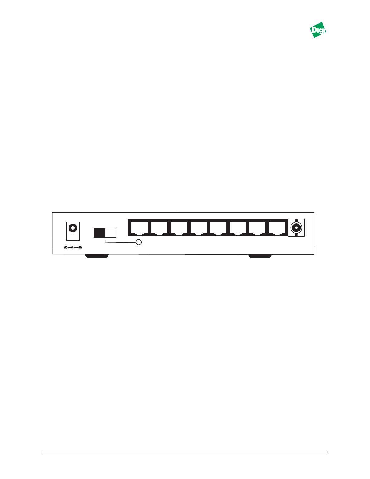
1. RJ-45 UTP Ports
The Hub is equipped with 8 RJ-45 UTP ports for making 10BASE-T hub-to-
workstation connections.
2. Cascade Enable Slide-Switch
Slide this switch to the right to enable cascading with straight UTP cables.
3. AC Adapter Port
Plug the AC adapter jack into this port
12348
4. BNC Port
The Hub is equipped with one BNC port for making 10BASE2 hub-to-
workstation connections
Model: MIL-910H 3
Page 4

Install Guide
Making Network Connections
The 910H hub has eight RJ-45 connectors for attaching up to eight 10BASE-T
based workstations. To establish such connections:
1. Ensure that both the Hub and the soon-to-be-connected workstation are in the
power off mode.
2. Plug one end of the UTP cable into an available 10BASE-T hub port.
3. Plug the other end into the workstation’s network interface card. The
following figure 3 illustrates a simple network topology using a 10BASE-T
hub-to-workstation connections.
The 910H hub has one BNC port for making 10BASE2 hub-to-workstation
connections. To establish such connections:
1. Ensure that both the Hub and the soon-to-be-connected workstation are in the
power off mode.
2. Plug one end of the coaxial cable into the Hub’s BNC port. Please refer to
figure 3 if you are having trouble locating this port.
3. Connect the other end of the coaxial cable to the workstation’s BNC connector
located on the network interface card. Please refer to figure 3 for an illustration
of such a connection.
Note:
If port 1 (BNC PORT) doesn’t connect to the hub port1 (BNC PORT) is indicated by the
alternate flashing of the green and yellow LEDs. The port 1 LEDs don’t flash after
connecting cable to port 1 and using hub.
The following diagram illustrates 10BASET and 10BASE-2 network connections
using the hubs BNC connector.
Normal Cascade
DC 7.5V
9
567
12348
185m max.
Figure 3
Model: MIL-910H 4
Page 5

Install Guide
Cascading Hubs
When you 10BASE-T network needs to grow past the eight available UTP
connections provided by the hub you should consider purchasing an additional
hub and cascading it with the original hub.
The 910H features a cascade enable switch. The switch allows you to use straight
UTP cables instead of the traditional cables when cascading hubs on port 9.
The following diagram illustrates 10BASE-T cascading:
Hub 1
DC 7.5V
Hub 2
DC 7.5V
Hub 3
DC 7.5V
Hub 4
Normal Cascade
Normal Cascade
Normal Cascade
Normal Cascade
Up to 7 PCs
9
9
9
567
Up to 6 PCs
567
Up to 6 PCs
567
Up to 7 PCs
12348
12348
12348
DC 7.5V
9
567
12348
Figure 4
Wall Mounting
After you have decided on a suitable location for mounting the hub, mark the
location for mounting two screws 165mm apart. At the marked locations, drill
two holes and insert a tapping screw in each hole. Align the hub’s wall-mount
slots with the screws and slide the hub down until the screws are securely last to
the hub. You can now complete the installation procedure by marking the
necessary cable connections.
Model: MIL-910H 5
Page 6

Legal
Regulatory Approvals
• FCC Class A
• UL 1950
• CSA 22 No. 950
• EN60950
• CE
– EN55022 Class B
– EN50082-1
Canadian EMI Notice
This Class A digital apparatus meets all the requirements of the Canadian Interference-Causing
Equipment Regulations.
Cet appareil numérique de la classe A respecte toutes les exigences du Règlement sur le matériel
brouilleur du Canada.
European Notice
Products with the CE Marking comply with both the EMC Directive (89/336/EEC) and the Low Voltage
Directive (73/23/EEC) issued by the commission of the European Community. Compliance with these
directives implies conformity to the following European Norms:
• EN55022 (CISPR 22) - Radio Frequency Interference
• EN50082-1 (IEC801-2, IEC801-3, IEC801-4) - Electromagnetic Immunity
• EN60950 (IEC950) - Product Safety
Digi International warrants to the original consumer or purchaser that each of its
products, and all components thereof, will be free from defects in material and/or
workmanship for a period of five years from the original factory shipment date. Any
warranty hereunder is extended to the original consumer or purchaser and is not
assignable.
Digi makes no express or implied warranties including, but not limited to, any implied
warranty of merchantability or fitness for a particular purpose, except as expressly set
forth in this warranty. In no event shall Digi be liable for incidental or consequential
damages, costs, or expenses arising out of or in connection with the performance of the
product delivered hereunder. Digi will in no case cover damages arising out of the
product being used in a negligent fashion or manner.
To Contact Digi
For prompt response when calling for service information, have the following information ready:
• Product serial number and rev.
• Date of purchase
• Vendor or place of purchase
Reach Digi Technical Support at 408/744-2751
Or E-mail at “sun-tech@dgii.com”
Address:1299 Orleans Drive
Sunnyvale, CA 94089
Voice: 408/744-2775
Fax: 408/744-2793
E-mail: info@dgii.com
Five-Year Limited Warranty
Doc #: 75411 Rev. A
 Loading...