

Page 1

Digi International Inc.
AccelePort
T1 Modem Bank
Installation and Configuration Guide
Part No: 90031300 Rev C
Page 2

The Digi logo is a registered trademark of Digi International Inc.
™
AccelePort
, T1 Modem Bank™ and EPC/X™ are trademarks of Digi International Inc. All other brand and product
names are the trademarks of their respective holders.
© Digi International Inc. 1997
All Rights Reserved
Information in this document is subject to change without notice and does not represent a commitment on the part of
Digi International.
Digi provides this document “as is”, without warranty of any kind, either expressed or implied, including, but not
limited to, the implied warranties of fitness or merchantability for a particular purpose. Digi may make improvements and/or changes in this manual or in the product(s) and/or the program(s) described in this manual at any time.
This product could include technical inaccuracies or typographical errors. Changes are periodically made to the
information herein; these changes may be incorporated in new editions of the publication.
Page 3

Table of Contents
Regulatory Statements................................................................................................................................................. viii
Federal Communications Commission (FCC) Statement .................................................................................... viii
FCC Part 68............................................................................................................................................................ ix
Industry Canada Compliance Statement ..................................................................................................................x
AccelePort T1 Modem Bank Overview..........................................................................................................................1
Unpacking ................................................................................................................................................................2
Planning the T1 WAN Interface......................................................................................................................................3
Connections to the WAN .........................................................................................................................................3
Carrier Approval...............................................................................................................................................3
CSU Mode.........................................................................................................................................................3
Line Build Out ..................................................................................................................................................4
CSU Specification.............................................................................................................................................4
T1 Cable Specification......................................................................................................................................4
Parameters Specified to the Carrier ..................................................................................................................5
Planning Worksheets................................................................................................................................................6
General Information..........................................................................................................................................6
Hardware Installation ......................................................................................................................................................8
T1 Modem Bank Power Supply Installation/Replacement......................................................................................8
T1 Modem Bank Standalone or Rack Installation.................................................................................................10
Standalone Installation Procedure...................................................................................................................11
Requirements for Rack Installations...............................................................................................................12
Mounting Bracket Installation for a 24-inch Rack ..................................................................................12
General Rack Installation Directions.......................................................................................................14
Daisy Chaining T1 Modem Bank Units.................................................................................................................16
Daisy Chain Example......................................................................................................................................17
Connecting a Modem......................................................................................................................................18
Daisy Chaining T1 Modem Bank Units and EPC/CON-16 Concentrators ....................................................19
Fault Tolerance ...............................................................................................................................................19
EPC/X Host Adapter Installation...........................................................................................................................20
PCI Host Adapters ..........................................................................................................................................20
Configuring the Host Adapter..................................................................................................................20
Installing the PCI Host Adapter in your Computer .................................................................................20
ISA Host Adapters..........................................................................................................................................21
Setting the I/O Port Address....................................................................................................................21
Factory-Set Jumper J1 .............................................................................................................................22
Installing the ISA Host Adapter in your Computer.................................................................................22
EISA Host Adapters........................................................................................................................................23
Factory-Set Jumpers ................................................................................................................................23
Installing the EISA Host Adapter in your Computer...............................................................................23
System Configuration..............................................................................................................................23
Connecting the EPC/X Host Adapter to the T1 Modem Banks.............................................................................25
Software Installation and Configuration .......................................................................................................................27
Setting the Node Number.......................................................................................................................................27
Installing Download...............................................................................................................................................29
POST Failure..........................................................................................................................................................30
Possible Problem.............................................................................................................................................31
Restarting POST .............................................................................................................................................31
Display Panel Status Indicators.......................................................................................................................31
Contents iii
Page 4

Software Installation for Novell Systems...............................................................................................................34
Introduction.....................................................................................................................................................34
Installing the EPC/X AIO Device Driver .......................................................................................................35
Installing the AIO Application........................................................................................................................35
Installing SNMP..............................................................................................................................................35
Installing QuickManager.................................................................................................................................35
Configuring the T1 Modem Banks .................................................................................................................36
Software Installation for Windows NT Systems....................................................................................................38
Installing the EPC/X Windows NT Device Driver.........................................................................................38
Installing the Windows NT SNMP Service....................................................................................................38
Windows NT 3.51....................................................................................................................................38
Windows NT 4.0......................................................................................................................................39
Installing RAS.................................................................................................................................................39
Installing the Management Software ..............................................................................................................39
Host System Installation..........................................................................................................................39
Remote System Installation .....................................................................................................................40
T1 Modem Bank Configuration.............................................................................................................................41
Configuring via QuickManager......................................................................................................................41
Configuring via the Terminal Port..................................................................................................................44
Configuring via the Display Panel..................................................................................................................45
Configuring via the Serial Port Interface........................................................................................................47
Configuration modification......................................................................................................................49
Equipment List.........................................................................................................................................51
System Information..................................................................................................................................52
Modem Switchhook Status......................................................................................................................53
Alarm Status ...........................................................................................................................................54
T1 Modem Bank Diagnostics........................................................................................................................................56
Running Diagnostics with QuickManager.............................................................................................................57
Running Diagnostics from the Display Panel........................................................................................................58
Running Diagnostics from the Terminal Port........................................................................................................59
Diagnostic Test Descriptions .................................................................................................................................62
Test 1: Front Panel Test.................................................................................................................................62
Test 2: RAM Test...........................................................................................................................................62
Test 3: Timer Test..........................................................................................................................................62
Test 4: Line Card Test.....................................................................................................................................63
Test 5: Modem Test .......................................................................................................................................63
Test 6: Sync Internal Loopback Test .............................................................................................................63
Test 7: Sync External Loopback Test............................................................................................................64
Test 8: EEPROM Test ...................................................................................................................................64
Test 9: Watchdog Test ...................................................................................................................................64
Component Removal and Installation ...........................................................................................................................65
Line Card Removal and Replacement....................................................................................................................66
Modem Card Removal and Installation/Replacement............................................................................................68
Modem Card Removal....................................................................................................................................68
Modem Card Installation/Replacement...........................................................................................................71
Power Supply Removal..........................................................................................................................................73
Fan Assembly Removal and Replacement.............................................................................................................75
Fuse Replacement ..................................................................................................................................................76
Connections to the Telephone Network........................................................................................................................77
Alarms on a T1 Span.......................................................................................................................................78
T1 Modem Bank Interaction...........................................................................................................................78
iv T1 Modem Bank
Page 5

Physical Specifications..................................................................................................................................................79
T1 Modem Bank Power Cord Specifications.........................................................................................................79
T1 Modem Bank Environmental Requirements.....................................................................................................80
T1 Modem Bank Rack Specifications....................................................................................................................80
Standalone Unit Specifications.......................................................................................................................80
Rack Specifications.........................................................................................................................................80
4U 19 Inch Rack System .........................................................................................................................80
4U 24 Inch Rack System .........................................................................................................................80
Daisy Chain Cables................................................................................................................................................81
Terminator Plug .....................................................................................................................................................81
T1 Loop Back Plug ................................................................................................................................................81
T1 Modem Bank Certification ...............................................................................................................................82
Glossary.........................................................................................................................................................................83
Appendix A — Memory Conflicts................................................................................................................................85
Contention for Memory Addresses........................................................................................................................85
ISA Host Adapters..........................................................................................................................................87
Conflicts Between 8-Bit and 16-bit Memory Devices....................................................................................87
EISA Host Adapters........................................................................................................................................88
Appendix B — Transmission Modes............................................................................................................................89
Appendix C — Terminal Port Cable.............................................................................................................................91
Appendix D — Specifications and Wiring Pin Diagrams............................................................................................92
Line Card Connector..............................................................................................................................................92
Connector for Sync Channels.................................................................................................................................93
Terminal Port .........................................................................................................................................................93
Appendix E — Generic T1 Modem Bank Wiring Modes.............................................................................................94
Eight-Wire Direct Wiring ......................................................................................................................................94
Four-Wire Direct Wiring........................................................................................................................................95
Restrictions on Daisy Chain Cable Lengths...........................................................................................................96
Eight-Wire Synchronous Modem Wiring..............................................................................................................97
Appendix F — Modem AT Command Set....................................................................................................................99
Basic AT Commands .............................................................................................................................................99
AT& (Ampersand) Commands .............................................................................................................................105
AT% (Percent) Commands ..................................................................................................................................111
AT\ (Backslash) Commands ................................................................................................................................112
AT- (Dash) Commands........................................................................................................................................116
AT" (Quote) Commands ......................................................................................................................................117
Class 1 FAX Commands......................................................................................................................................118
Class 2 FAX Commands......................................................................................................................................120
Class 2 FAX Responses................................................................................................................................127
S Registers............................................................................................................................................................128
S Register Definitions...................................................................................................................................129
Result Codes.........................................................................................................................................................143
Display Format Options................................................................................................................................143
Extended Message Options...........................................................................................................................144
Negotiation Progress Messages ....................................................................................................................146
Index............................................................................................................................................................................149
Contents v
Page 6

List of Figures
Figure 1 T1 Modem Bank Chassis, Front View.......................................................................................................1
Figure 2 Power Supply.............................................................................................................................................9
Figure 3 Line Card and Synchronous Cable Connections for Standalone T1 Modem Bank.................................11
Figure 4 Bracket Position For 19-inch Rack..........................................................................................................12
Figure 5 Bracket Position For 24-inch Rack..........................................................................................................13
Figure 6 T1 Modem Bank Unit Spacer..................................................................................................................14
Figure 7 Line Card .................................................................................................................................................15
Figure 8 Synchronous Ports and Terminal Port.....................................................................................................16
Figure 9 Two Daisy Chains of T1 Modem Banks to be Connected Locally .........................................................17
Figure 10 Remote T1 Modem Bank Units...............................................................................................................18
Figure 11 Mixing EPC Concentrators with T1 Modem Bank Units........................................................................19
Figure 12 DIP Switch Settings for I/O Port Address...............................................................................................21
Figure 13 EPC/X Host Adapter Connected Locally to T1 Modem Banks ..............................................................25
Figure 14 Local and Remote T1 Modem Bank Units..............................................................................................26
Figure 15 EPC/X Host Adapter Connected to Concentrators and T1 Modem Bank Units .....................................26
Figure 16 T1 Modem Bank Display Panel...............................................................................................................28
Figure 17 Main Screen.............................................................................................................................................36
Figure 18 T1 Modem Bank Configuration Screen...................................................................................................37
Figure 19 Line Card Status Display.........................................................................................................................42
Figure 20 Line Card Options Display......................................................................................................................43
Figure 21 Modem Test Results ................................................................................................................................57
Figure 22 Line Card .................................................................................................................................................66
Figure 23 Modem Card............................................................................................................................................69
Figure 24 Quick Manager Modem Revision Screen................................................................................................71
Figure 25 Power Supply...........................................................................................................................................74
Figure 26 Fan Assembly ..........................................................................................................................................75
Figure 27 AC Power Inlet ........................................................................................................................................76
Figure 28 T1 Modem Bank and Public Switched Telephone Network ...................................................................77
Figure 29 Functional Block Diagram of the T1 Modem Bank ................................................................................78
Figure 30 Typical PC Memory Usage - 1st Megabyte.............................................................................................86
Figure 31 Simple Terminal Cable............................................................................................................................91
Figure 32 RJ-45 Plug ...............................................................................................................................................92
Figure 33 Eight-Wire Direct Daisy Chain Cable Wiring.........................................................................................94
Figure 34 Four-Wire Direct Daisy Chain Cable Wiring..........................................................................................95
Figure 35 RS-232 Synchronous Modem Cables......................................................................................................97
Figure 36 RS-422 Synchronous Modem Cables......................................................................................................98
vi T1 Modem Bank
Page 7

List of Tables
Table 1 T1 Modem Bank Shipping Carton Contents..............................................................................................2
Table 2 CSU Technical Description.......................................................................................................................4
Table 3 Requirements for T1 Modem Bank Setup.................................................................................................6
Table 4 Error Message Codes...............................................................................................................................30
Table 5 Display Panel Status Codes .....................................................................................................................32
Table 6 Component Level Troubleshooting.........................................................................................................65
Table 7 Types of Modem Cards............................................................................................................................70
Table 8 Daisy Chain Cable Length vs. Baud Rate................................................................................................96
Table 9 Supported FAX Transmit/Receive Modulations ...................................................................................119
Contents vii
Page 8

Regulatory Statements
Federal Communications Commission (FCC) Statement
Radio Frequency Interference (RFI)
This equipment generates and uses radio frequency energy, and if not installed and used in strict accordance with
manufacturer’s instructions, may cause interference to radio and television reception. This equipment has been typetested to verify that it complies with the limits for a Class A computing device in accordance with specifications in
Subpart J of Part 15 of FCC Rules (Appendix B of OST Bulletin No. 62), which are designed to provide reasonable
protection against such interference in a residential installation. However, this does not assure that such interference
will not occur in a particular installation. If this equipment does cause interference to radio or television reception,
which can be determined by turning your computer OFF and ON, the user is encouraged to attempt correction of the
interference by one or more of the following measures:
1. Reorient the receiving antenna.
2. Relocate your computer with respect to the receiver.
3. Move your computer away from the receiver.
4. Plug your computer into a different outlet so the computer and receiver are not on the same circuit.
If these measures fail to eliminate the interference, the user should contact either the distributor or an experienced
radio/television technician for further suggestions. The user may also find the following booklet (prepared by the
FCC) helpful:
“How to Identify and Resolve Radio/TV Interference Problems”
This booklet is available from the U.S. Government Printing Office, Washington, DC. Request should be made for
Stock No. 004000003454.
viii T1 Modem Bank
Page 9

FCC Part 68
FCC Registration: 5TLUSA-23932-DD-N
Ringer Equivalence Number: 0.0B
This T1 Modem Bank complies with Part 68 of FCC Rules. On the back of the T1 Modem Bank is a label that
includes the FCC Registration Number and Ringer Equivalence Number (REN) for this T1 Modem Bank. If
requested, this information must be provided to the telephone company.
The REN is used to determine the number of devices you may connect to your telephone line and still have all of
those devices ring when your number is called. In most, but not all, areas, the sum of the RENs of all devices
connected to one line should not exceed five (5.0). To be certain of the number of devices you may connect to your
line, as determined by the REN, you should contact your local telephone company to determine the maximum REN
for your calling area.
If your T1 Modem Bank interferes with the network, the Telephone Company may discontinue your service
temporarily. If possible, they will notify you in advance. If advance notice isn’t practical, you will be notified as
soon as possible. You will be informed of your right to file a complaint with the FCC.
Your telephone company may make changes in its facilities, equipment, operations or procedures that could affect
the proper function of your T1 Modem Bank. If it does, you will be notified in advance to give you an opportunity to
maintain uninterrupted telephone service.
Problems with your T1 Modem Bank
If you experience trouble with your T1 Modem Bank, please contact Digi Technical Support for information on
obtaining service or repairs. The telephone company may ask you to disconnect the T1 Modem Bank from the
network until the problem has been corrected or you are sure that the equipment is not malfunctioning.
This equipment may not be used with coin-operated telephones. Connection to Party Line Service is subject to state
tariffs.
Regulatory Statements ix
Page 10

Industry Canada Compliance Statement
This Class A digital apparatus meets the requirements of the Canadian Interference-Causing Equipment Regulations.
It complies with CSA 22.2 No. 950 for safety, ICES 003 for EMC, and ICCS 003 for Telecom.
Cet appareil numérique de la classe A respecte toutes les exigences du
Canada. Cet appareil est conformément aux exigences de CSA 22.2 No. 950 pour la sécurité, ICES 003 pour EMC et
ICCS pour les télécommunications.
Règlement
sur le matériel brouilleur du
x T1 Modem Bank
Page 11
AccelePort T1 Modem Bank Overview
The Digi AccelePort T1 Modem Bank is a high speed Wide Area Network (WAN) interface for Windows NT and
Novell environments. The T1 Modem Bank system is composed of two major parts: a host-installed Enhanced
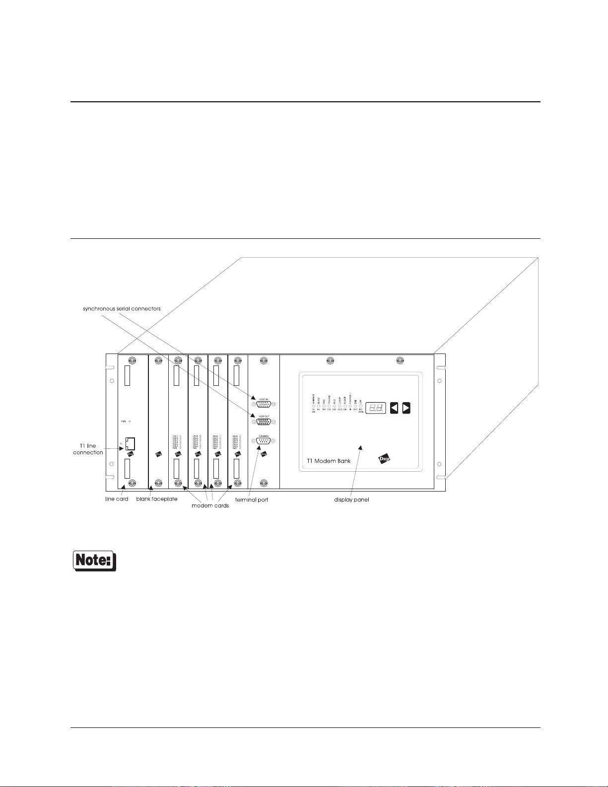
Performance Concentrator (EPC/X) adapter and a rack mountable or table top system cabinet. Figure 1 shows a front
view of the T1 Modem Bank system cabinet.
Figure 1 T1 Modem Bank Chassis, Front View
Some versions of the T1 Modem Bank have a second connector on the line card labeled “PBX.”
This connector is non-functional.
The T1 Modem Bank multiplexes up to 24 asynchronous V.34 modems onto one DS-1 (four-wire T1) WAN circuit.
For a discussion of the terms and concepts related to T1 lines and the devices that connect to them, see “Connections
to the Telephone Network” on page 77. The Glossary on page 83 defines the terms and acronyms used in this
manual.
Overview 1
Page 12

Unpacking
Table 1 documents typical shipment packaging contents of the T1 Modem Bank. The components should be checked
in upon arrival; notify your salesperson if the order is incomplete.
The T1 Modem Bank is shipped with proper shock insulation material. If the unit needs to be shipped, use the
original shipping carton. If the original packaging is unavailable, contact Digi for replacement packaging.
Table 1 T1 Modem Bank Shipping Carton Contents
Description Part Number
The complete system includes:
Carton 1
System unit 50000471-xx
Accessory box 76000205
Power supply 50000468-01
Carton 2
EPC/X Host Adapter ISA EISA PCI
77000146 77000234 77000427
Available additional components:
Power Supply card 76000206
T1 line card 76000207
Modem card 76000208
Fan card 76000209
T1 Modem Bank Installation Guide 90031300
Terminator plug 60000388
2
T1 Modem Bank
Page 13

Planning the T1 WAN Interface
This section describes planning the T1 Modem Bank interface to the carrier facility. The configuration of the T1
Modem Bank must match the requirements of the T1 line specified by the carrier.
Connections to the WAN
Connection to the telephone carrier facility is handled from the line card, via a T1 line.
Carrier Approval
Contact your carrier for approval before beginning the actual installation. By doing this, you will help to ensure
proper configuration of the line and the T1 Modem Bank. This protects the T1 Modem Bank and telephone network
from damage due to an improper configuration.
After the T1 Modem Bank has been installed on the network, it is good practice to contact the carrier before
removing or disconnecting the T1 Modem Bank. If you disconnect the T1 Modem Bank from the WAN, the carrier
may suspend your T1 service. RJ-45 connectors are available which ensure loopback upon disconnection of user
equipment to ensure that the line from the central office is properly terminated. Most T1 carriers provide a “smart
jack” which will loop the T1 carrier when the T1 Modem Bank is disabled.
CSU Mode
• When the line card is in the CSU mode of operation (also known as “Long Haul”), it supports 6,000 feet of 24
AWG twisted-pair cable.
• In the non-CSU mode of operation (also known as “Short Haul”), the DSX-1 function supports a maximum
cable distance of 655 feet. This mode allows the T1 Line card to interface to PBX devices.
Planning the T1 Interface 3
Page 14

Line Build Out
After the T1 Modem Bank is installed, the carrier will determine the correct setting for Line Build Out (LBO).
However, certain determinations based on the following information will need to be entered into your computer.
• CSU mode Line compensation: Line attenuation can be set to one of the following: -0.0dB, -7.5dB, -15.0dB,
and -22.5dB. Your T1 installer will inform you of the correct setting.
• DSX-1 Mode Transmit line buildout: For line compensation, your T1 installer will select a cable length
between 0 and 655 feet based upon line length.
CSU Specification
Table 2 CSU Technical Description
Line Frequency 1.544 Mb/s +/- 200 b/s
Line Code AMI or B8ZS
Critical Circuitry Power Source Dry Span, CSU powered form local AC power source
Line Framing D4 or ESF
Line Loopback (LLB) Set Inband Code (00001) repeating binary pattern (per AT&T Pub 54016 and
ANSI T1.403)
Line Loopback (LLB) Reset Inband Code (001) repeating binary pattern (per AT&T Pub 54016 and ANSI
T1.403)
Line Build Out 0.0, -7.5, -15.0, or -22.5 dB of attenuation
Pulse Density and Consecutive Zeros
Enforcement
In accordance with requirements of AT&T Pub 62411
T1 Cable Specification
Transmitting T1 signals requires two 24 AWG stranded unshielded twisted pair Category 5 cables. A 15’ cable
meeting these specifications is shipped with the T1 Modem Bank.
4
T1 Modem Bank
Page 15

Parameters Specified to the Carrier
Certain parameters are specified to the carrier when provisioning the T1 line.
You will need to provide the following information to a T1 facility provider.
• Individual Access Line Select the Phone service or Line Pooling Arrangement, which is sometimes termed
Multi-Hunt Grouping. With Line Pooling, one phone number is assigned to a group of end terminals, and the
first available terminal will receive the call.
• B8ZS or AMI line code B8ZS is preferred.
• ESF or D4 framing format ESF is preferred because of its enhanced diagnostic and maintenance capabilities.
• Supervisory Signaling Method Robbed bit signaling; ground start, loop start, immediate start, or wink start
• Dual-tone Multi Frequency (DTMF) or pulse-dial addressing DTMF preferred
• Be sure you ask for a “trunk-side” T1. Most carriers will provision “line-side” T1s by default, which will cause
lower speed modem connections.
Planning the T1 Interface 5
Page 16

Planning Worksheets
The T1 Modem Bank must be configured to match the provisioning of the T1 line from the carrier.
General Information
Required information includes the following:
• The identity of the WAN manager for your local and remote sites
• The identification of the TELCO providing the WAN
Table 3 Requirements for T1 Modem Bank Setup
Requirements Description
Location of the T1 Modem
Bank
Active T1 line One or more active and installed T1 lines from the WAN service with at least two
Ground Start or Loop Start CSU supervision mode
Circuit ID Identifier used by the T1 provider to refer to the line. It refers only to the T1 line and
You can make as many copies as you need of the worksheet on the following page. A copy of this worksheet should
also be filled out for both the local and remote sites.
The T1 Modem Bank must be positioned where it can be connected to the WAN
within the specified cable limits.
channels assigned.
is not associated with individual phone numbers. You must keep track of the circuit
ID number for each line, since if you experience trouble on the T1 line, the service
provider will need to know this number.
6
T1 Modem Bank
Page 17

T1 Modem Bank Worksheet
Type Number or Checkmark
(√)
Circuit ID # __________________ This is a code assigned by your
service provider, one per T1 line
Lead phone
number
Span Type ________
Frame Format ______
Line
Encoding
Signaling ______
__________________ Master phone number or first phone in
the sequence to receive a call.
________
______
______
______
______
Description
Long Haul
Short Haul
ESF
D4
B8ZS
AMI
Ground Start
Loop Start
Attenuation
EQ Gain
(applicable
only for Long
Haul)
______
______
______
______
______
______
______
Wink Start
Immediate Start
Line Build-out:
0.0 dB
-7.5 dB
-15.0 dB
-22.5 dB
Short haul distance:
0 - 655 ft.
Low
High
Planning the T1 Interface 7
Page 18

Hardware Installation
This section describes the following procedures:
1. T1 Modem Bank power supply installation/replacement
2. T1 Modem Bank standalone or rack installation
3. T1 Modem Bank daisy chaining
4. EPC/X host adapter installation
5. EPC/X host adapter connection to the T1 Modem Bank units.
T1 Modem Bank Power Supply Installation/Replacement
The T1 Modem Bank operates with either a single power supply installed or with two power supplies installed. Dual
power supplies allow a T1 Modem Bank to share load balancing so that one power supply can take over if the other
power supply becomes inoperable. To install a power supply (or supplies) into a new T1 Modem Bank unit, or to
replace or add a power supply in an existing T1 Modem Bank unit, follow the directions in this section. See “Power
Supply Removal” on page 73 if you need instructions for removing a power supply from a T1 Modem Bank.
8
T1 Modem Bank
Page 19

Figure 2 Power Supply
You can install a second power supply into a T1 Modem Bank that already has an existing
•
power supply installed without having to power-down the T1 Modem Bank.
Wear a grounding strap while performing this procedure to prevent electrical discharge.
•
Avoid touching the fan during this procedure since the fan blade could cause harm.
•
When handling the power supply printed circuit board, do not touch the edge connector that
•
connects to the distribution board because damage to the board may result.
1. If the display panel faceplate on the T1 Modem Bank is closed, loosen the two captive screws on the display
panel faceplate; carefully pull down the hinged display panel faceplate.
2. Slide the power supply into an available slot. It may be necessary to apply some force to properly seat the power
supply.
3. Use the ON/OFF switch at the back of the T1 Modem Bank to power it up if it is not already powered-up. If you
installed a second power supply into a unit while the unit was powered-up, no reset is needed because hot swap
capabilities are integrated on power supplies.
4. It may take a few seconds for the LED on the power supply board to light to indicate that the power supply is
operational.
Hardware Installation 9
Page 20

T1 Modem Bank Standalone or Rack Installation
You have the option of using the T1 Modem Bank in a standalone, table-top configuration or in a rack-mounted
configuration. Directions for both configurations are provided in this section.
• Make sure the T1 Modem Bank is powered-down before you install it.
• Do not block the sides of the T1 Modem Bank since this will impede airflow.
• The T1 Modem Bank is shipped from the factory with four “feet” installed on the bottom of
the unit. If you remove the feet, you must ensure that the T1 Modem Bank will have at least
1U (1.75 inches) of clearance beneath it in order to prevent airflow from being impeded.
10
T1 Modem Bank
Page 21
Standalone Installation Procedure
Tools needed: Phillips screwdriver; flat blade screwdriver
1. Place the T1 Modem Bank on a flat surface within 6’ 7” (2m) of a power outlet.
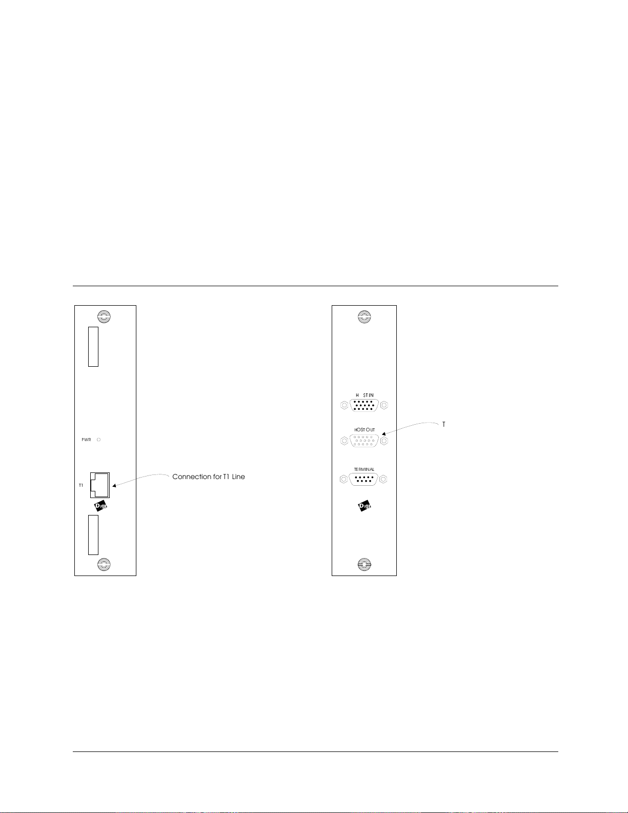
2. Attach the terminator plug to the connector labeled HOST OUT on the HOST IN/OUT and Terminal faceplate.
See Figure 3.
3. Plug the power cord into an outlet.
5. Insert the RJ-45 plug on the T1 line cable into the jack marked T1 on the Line card faceplate. See Figure 3.
6. Refer now to the instructions in “EPC/X Host Adapter Installation” on page 19.
Figure 3 Line Card and Synchronous Cable Connections for Standalone T1 Modem Bank
3:5
7
&RQQHFWLRQ IRU 7 /LQH
+267 287
7(50,1$/
7HUPLQDWRU 3OXJ WR E H LQVWDOOHG KHUH
Hardware Installation 11
Page 22

Requirements for Rack Installations
The T1 Modem Bank chassis is made to be inserted into a standard 19-inch or a 24-inch equipment rack. The T1
Modem Bank is shipped from the factory with two rack-mounting brackets (“ears”) installed for a 19-inch rack. If
you wish to install a T1 Modem Bank into a 19-inch rack, go now to the instructions in “General Rack Installation
Directions” on page 14. Before you can install a T1 Modem Bank into a 24-inch rack, you must first remove the
rack-mounting brackets and then re-install them in the correct position for a 24-inch rack.
Mounting Bracket Installation for a 24-inch Rack
Tools needed: Phillips screwdriver; flat blade screwdriver
1. The rack-mounting brackets must be removed from their 19-inch rack position. Remove the three screws that
fasten each of the brackets to the chassis. (See Figure 4).
Figure 4 Bracket Position For 19-inch Rack
2. Re-install the brackets so that the long sides of the brackets extend outward from the chassis; the shorter sides of
the brackets must be flat against the sides of the chassis as shown in Figure 5.
12
T1 Modem Bank
Page 23

3. Line up the circular holes in a bracket with the circular holes on a side of the T1 Modem Bank, and use two of
the screws to fasten the bracket to the chassis.
Do not use the oval slots on a bracket to connect the bracket to the T1 Modem Bank.
Figure 5 Bracket Position For 24-inch Rack
4. Follow “General Rack Installation Directions” on page 14 when you have installed two brackets to each T1
Modem Bank unit.
Hardware Installation 13
Page 24

General Rack Installation Directions
• When multiple units will be mounted in the rack, install a T1 Modem Bank unit in
the first chassis slot at the bottom of the rack, then work upward. This prevents
cables from becoming tangled, and it maintains the lowest possible center of gravity
to prevent the rack from falling over.
• Multiple T1 Modem Bank units within the confined space of a rack may cause
higher operating temperatures. The recommended maximum external ambient
operating temperature of a T1 Modem Bank unit is 40° C. Since the T1 Modem
Bank takes in air from the vent on the bottom of the unit and exhausts the air out
the vent on the side, make sure that neither vent is blocked. The T1 Modem Bank is
shipped from the factory with four “feet” installed on the bottom of the unit. If you
remove the feet, you must ensure that each T1 Modem Bank will have at least 1U
(1.75 inches) of clearance beneath it in order to prevent airflow from being
impeded. You may connect a Digi-supplied spacer (See Figure 6) to the rack
between each T1 Modem Bank unit in order to ensure the required clearance. In
general, eight T1 Modem Bank units can be stacked in a six-foot rack; five units
can be stacked in a 4-foot rack.
• The power cord is limited to 6’ 7” (or 2 m) in length. This is sufficient since most
racks provide internal power outlets.
• The T1 Modem Bank is rated at 1.2 Amps when the current is drawn from a 125 V
AC supply. Due to the nature of the internal switching power supply, the power
rating of the AC supply circuit should be derated to 75% of its rated capacity when
calculating how many units can be connected to the AC supply. For example, a 15
Amp circuit should be derated to 11.25 Amps.
• The T1 Modem Bank should be used only with earth grounded outlets. The earth
ground connection of the three prong cord should be maintained even when the unit
is not connected directly to the AC supply line through a power strip.
Figure 6 T1 Modem Bank Unit Spacer
14
T1 Modem Bank
Page 25
1. Installing the T1 Modem Bank into the rack requires two people since the T1 Modem Bank is heavy. Note that
handles are provided on the T1 Modem Bank to aid in rack installation. They are part of the chassis and are
located on the front of the T1 Modem Bank near the outer edges of the chassis. As one person holds the chassis
in the appropriate location in the rack, the other person must ensure that
all
the oval slots on the rack-mounting
brackets line up with the correct holes in the rack before fastening the chassis to the rack with the screws
provided. Tighten all the screws with a screwdriver.
2. Repeat step 1 to install other T1 Modem Bank units in the rack.
3. Plug the power cord of each T1 Modem Bank into an outlet.
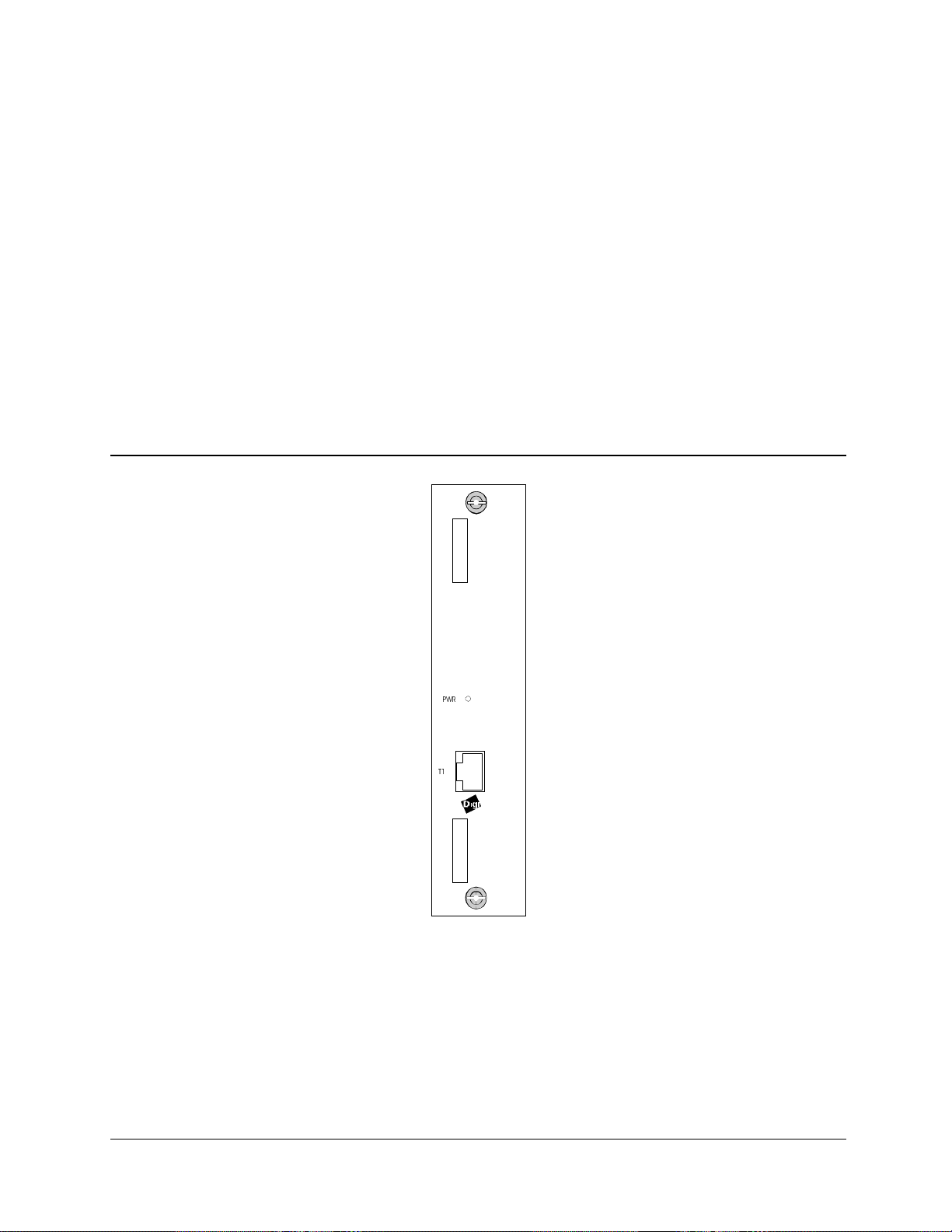
4. Insert the RJ-45 plug from the T1 line cable into the T1 jack on the Line card faceplate for each T1 Modem
Bank and label the cable. (See Figure 7). A suggested method of labeling is to label each T1 line alphabetically,
starting from the top.
5. Refer to the next section, “Daisy Chaining T1 Modem Bank Units.”
Figure 7 Line Card
3:5
7
Hardware Installation 15
Page 26
Daisy Chaining T1 Modem Bank Units
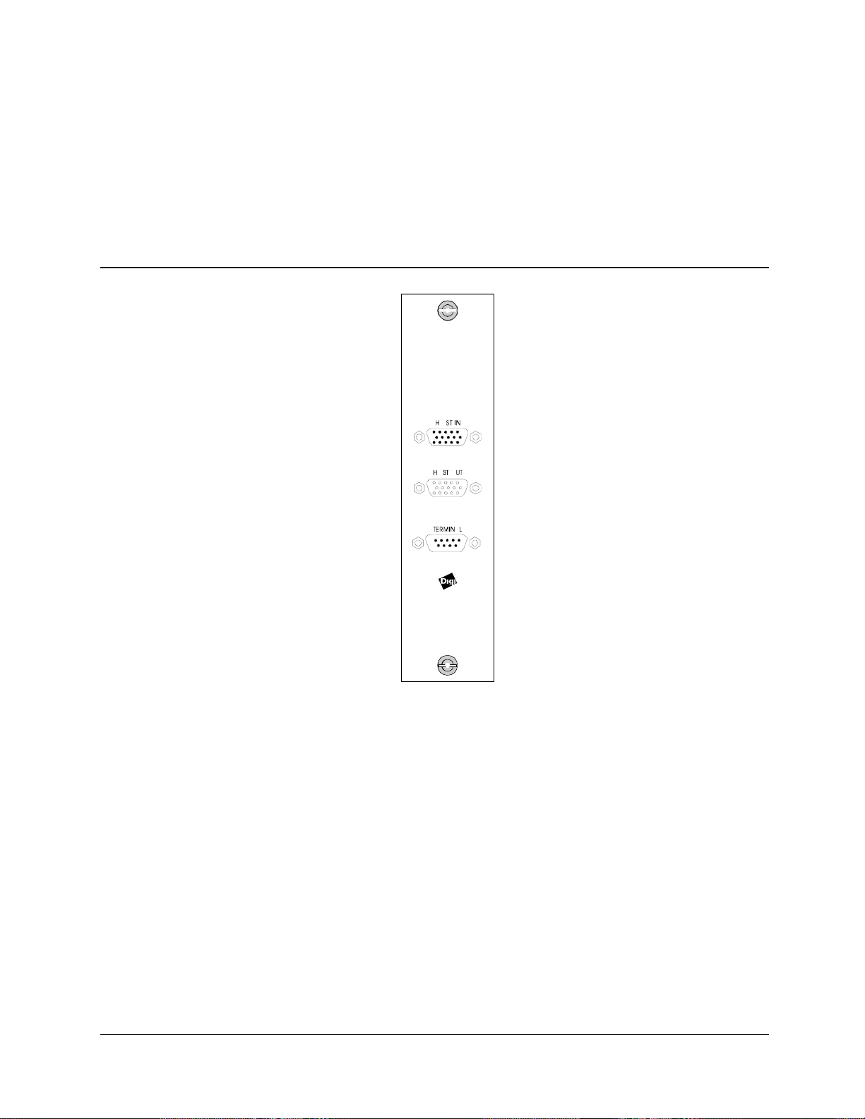
The HOST OUT connector of each unit must be connected to the HOST IN connector of the next unit in the daisy
chain. A terminator plug is then installed on the HOST OUT connector of the last unit in the daisy chain. See Figure
8.
Figure 8 Synchronous Ports and Terminal Port
16
T1 Modem Bank
Page 27
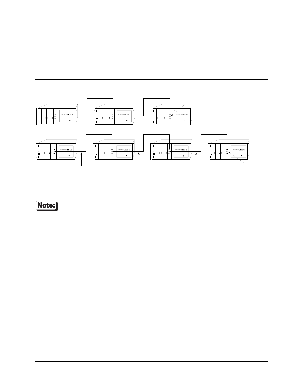
Daisy Chain Example
While setting up daisy chains, refer to the example shown in Figure 9 and the directions that follow.
Figure 9 Two Daisy Chains of T1 Modem Banks to be Connected Locally
7HUPLQDWRU SOXJ
LQVWDOOHG RQ +RVW 2XW
SRUW
TM
TM TM TM TM
6WDQGDUG G DL V\ FKDLQ FDEOH ZLUH GLU HFW RU ZLUH GLUHFW
TMTM
7HUPLQDWRU SOXJ
LQVWDOOHG RQ +RVW 2XW
SRUW
You can connect whatever number of T1 Modem Bank units you want in each of 2 daisy chains,
as long as the total number of units in both daisy chains does not exceed 7 for each EPC/X host
adapter that will be installed in your computer. For example, all 7 of the units in Figure 9 could
be connected in one daisy chain, and there would be no units in the second daisy chain.
1. Use daisy chain cables to connect the HOST OUT port of each T1 Modem Bank to the HOST IN port of the T1
Modem Bank which is next in the chain.
2. Connect the terminator plug to HOST OUT on the last T1 Modem Bank in the rack to allow loopback to the
motherboard.
3. Label and secure all cables.
Hardware Installation 17
Page 28
• Do not connect wires to pins 12 or 13 in a standard daisy chain cable—serious damage
could result.
• Never use VGA extension cable or any other cable that has all 15 pins wired.
• Do not use a standard DB15 video cable
• To build a custom daisy chain cable, follow the wiring mode shown in Figure 33 on page
94 or Figure 34 on page 95. Alternatively, contact your Digi sales representative.
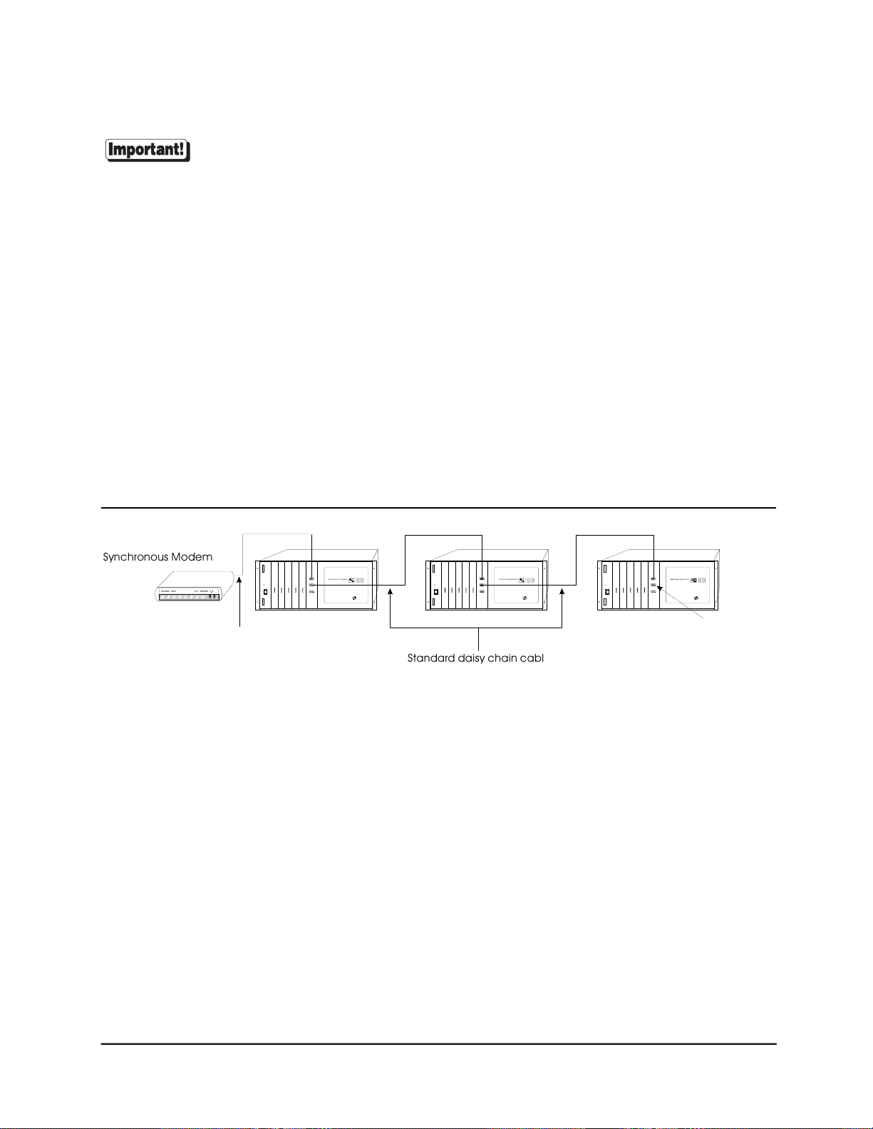
Connecting a Modem
To connect a modem to T1 Modem Banks, use the cabling shown in Figure 35 (page 97) or Figure 36 (page 98),
depending upon your modem type (RS-232 or RS-422). Connect additional T1 Modem Bank units with Eight-Wire
Direct cables (or the standard daisy chain cables shipped with the unit) as shown in Figure 10. Be sure to install the
terminator plug on the HOST OUT port of the last T1 Modem Bank.
Figure 10 Remote T1 Modem Bank Units
6\QFKURQRXV 0RGHP
0RGHP 7HFK )$67 0RGHP 9
6' 5' &' 2+ 75
6\QFKURQRXV PRGHP FDEOH
PRGHP WR 70RGHP %DQN
TM TM TM
7HUPLQDWRU SOXJ
LQVWDOOHG RQ +RVW 2XW
6WDQGDUG GDLV\ FKD LQ FDEOH
PXVW E H ZLUH GLUH FW
SRUW
18
T1 Modem Bank
Page 29
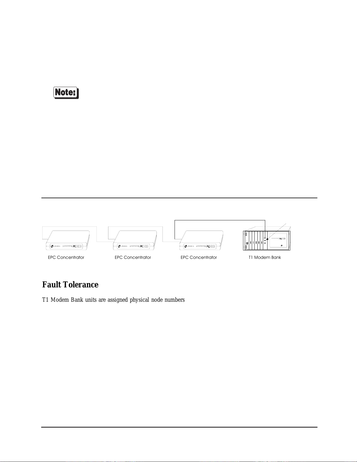
Daisy Chaining T1 Modem Bank Units and EPC/CON-16 Concentrators
A T1 Modem Bank can be installed in an existing system comprised of EPC/CON-16 concentrators. See Figure 11.
• Because existing EPC concentrators are assigned node numbers by the host each time the
Figure 11 Mixing EPC Concentrators with T1 Modem Bank Units
software is booted, any added T1 Modem Bank units must follow the EPC concentrators in
the daisy chain.
• The last T1 Modem Bank in a daisy chain must have a terminator plug installed on its
HOST OUT port. Individual T1 Modem Bank units are not shipped with terminator plugs.
Terminator plugs are shipped with EPC/X host adapters only.
• All EPC concentrators which will be connected to the EPC/X host adapter via synchronous
modems must be of the newer type (plastic) if a T1 Modem Bank is to be added to the
system.
7HUPLQ DW RU S OX J
LQVWDOOHG RQ +RVW 2XW
SRUW
(3&&21
7' 5' 576 &76' 65 '&''75 5, 2)& ,)&
(3&&21
7' 5' 576 &76 '65 '&' '75 5, 2)& ,)&
7' 5' 576 &76 '65 '&' '75 5, 2)& ,)&
(3&&21
(3& &RQFHQWUDWRU(3& &RQFHQWUDWRU(3& &RQFHQWUDWRU
7 0RGHP %DQN
TM
Fault Tolerance
T1 Modem Bank units are assigned physical node numbers (set by the operator during installation—see page 27).
The node number is used to route data to and from a specific T1 Modem Bank unit. If a particular T1 Modem Bank
is turned off or removed from the daisy chain, the 24 channels on that T1 Modem Bank become unavailable to the
system, but the rest of the system remains unaffected. Since the T1 Modem Bank unit’s HOST IN and HOST OUT
ports are of the opposite gender, a T1 Modem Bank can be removed from the middle of a daisy chain, and the cables
can be connected so that the chain remains unbroken. To remove the last T1 Modem Bank unit, simply plug a
terminator plug into the end of the daisy chain cable.
When the hook-up is complete, go to “EPC/X Host Adapter Installation” on page 19 for further instructions.
Hardware Installation 19
Page 30

EPC/X Host Adapter Installation
The Digi EPC/X host adapter is an intelligent dual-channel synchronous communication board which plugs into a
slot in your computer’s bus. The adapter provides an interface between the computer and a single T1 Modem Bank
or a series of daisy-chained T1 Modem Banks and/or EPC concentrators.
Before installing your Digi EPC/X host adapter, be sure to write down its serial number.
PCI Host Adapters
Configuring the Host Adapter
No hardware configuration is required for PCI host adapters.
Installing the PCI Host Adapter in your Computer
1. Turn off your computer’s power and remove the cover. Refer to your computer’s manual for instructions on
cover removal and option board installation and cautions.
2. Locate an available PCI slot in your computer and remove the slot plate.
3. Plug the host adapter into the PCI slot and screw the endplate to the computer chassis.
4. Replace your computer’s cover.
PCI EPC/X host adapters are shipped with a diagnostic diskette. The MS-DOS based diagnostic
program, UD-PCI.EXE, will help verify correct installation of the host adapter, and help
identify possible hardware problems. See the text file, USERPCI.TXT, for complete
instructions, and RELNOT-P.TXT for release information.
5. When you have verified that the host adapter has been correctly installed, follow the instructions in “Connecting
the EPC/X Host Adapter to the T1 Modem Banks” on page 25.
20
T1 Modem Bank
Page 31

ISA Host Adapters
Setting the I/O Port Address
The ISA EPC/X host adapter uses four bytes of address space on the host computer’s I/O bus. Before installing the
host adapter, the board’s I/O port starting address must be set on DIP switch SW1 (located on the top of the board).
To insure flexibility, seven I/O port address ranges are available: 108h-10Bh, 118h-11Bh, 128h-12Bh, 208h-20Bh,
228h-22Bh, 308h-30Bh and 328h-32Bh. Choose one of the starting addresses and set SW1-1, 2 and 3 as shown in
Figure 12 below.
Figure 12 DIP Switch Settings for I/O Port Address
OFF
1234
108h
OFF
1234
208h
OFF
1234
OFF
1234
118h
OFF
1234
228h
OFF
1234
128h
OFF
1234
308h
328h
Record the I/O port address that you set. You will need to know the address when you install
the device driver.
Hardware Installation 21
Page 32

Factory-Set Jumper J1
There is one jumper, J1, on the host adapter. This jumper is set in the factory and must not be changed.
Installing the ISA Host Adapter in your Computer
1. Turn off your computer’s power and remove the cover. Refer to your computer’s manual for instructions on
cover removal and option board installation and cautions.
2. Locate an available 16-bit AT slot in your computer and remove the slot plate.
3. Plug the host adapter into the ISA slot and screw the endplate to the computer chassis.
4. Replace your computer’s cover.
5. Go to “Connecting the EPC/X Host Adapter to the T1 Modem Banks” on page 25.
22
T1 Modem Bank
Page 33

EISA Host Adapters
Factory-Set Jumpers
There are three jumpers, J1-J3 on the EISA EPC/X host adapter. These are set in the factory, and must not be
changed.
Installing the EISA Host Adapter in your Computer
1. Turn off your computer and disconnect any attached peripheral devices.
2. Remove the cover from the computer. Refer to your system’s documentation for cover removal instructions and
for other add-in board installation instructions and precautions.
3. Unscrew and remove the external slot cover plate from the slot into which you wish to install the EPC/X host
adapter.
4. Carefully insert the EPC/X host adapter into the slot in the computer. Press the board firmly into the EISA bus
connector, and replace the screw in the host adapter’s endplate.
5. Replace the computer’s cover.
System Configuration
1. Boot up your EISA system with the EISA Configuration Diskette. During the boot-up process, the system
should display a message to the effect that an unknown board has been found. This is the EPC/X host adapter installed in the previous procedure.
2. When the boot-up has been completed, copy the file !DBI0301.CFG from the Digi distribution diskette to
your EISA system’s Configuration Diskette.
3. Run the configuration program to add the EISA host adapter.
4. From the Edit pull-down menu, select Add. The program will display a list of the .CFG configuration files for
boards; select EPC/X Host Adapter. (If this is not displayed as an option, you may not have copied the .CFG
file to the correct directory in Step 2.
5. Use a mouse, or the arrow keys and Tab key to pull down the View menu, and choose Detailed by Slot. Next,
use the up and down arrow keys to move to “EPC/X Host Adapter” and press <Enter>. You should see a
screen similar to the following:
Hardware Installation 23
Page 34

6. Place the cursor on “Dual-Ported Mem Address” and press <Enter>. A screen similar to the following will
appear:
The following address choices are available:
Below 1 Megabyte:
*
80000h 88000h 90000h 98000h
A0000h A8000h B0000h B8000h
C0000h C8000h D0000h D8000h
E0000h E8000h F0000h F8000h
Above 1 Megabyte:
F0000000h F1000000h F2000000h F3000000h
F4000000h F5000000h F6000000h F7000000h
F8000000h F9000000h FA000000hFB000000h
FC000000h FD000000hFE000000h FF000000h
* Although there are 16 choices offered for memory start addresses below 1 megabyte, a limited number of these
choices is likely to be available. Of the 16, the best choices are probably D0000 and D8000. See Appendix A
on page 85 for more information.
Multiple EISA EPC/X host adapters may share the same addresses.
7. Use the cursor keys to select one of the listed addresses, or press <Enter> to accept what the configuration program has chosen. Write this address down—you will need to know it when installing the device driver software.
8. Leave the Dual-Port Mem Enbl/Dsbl at “Disabled”.
9. Leave the Interrupt Configuration at “Disabled”.
10. Pull down the SYSTEM menu, and choose “Exit”. Make sure that you SAVE the new configuration as the
program suggests.
11. Go to “Connecting the EPC/X Host Adapter to the T1 Modem Banks” on page 25.
24
T1 Modem Bank
Page 35

Connecting the EPC/X Host Adapter to the T1 Modem
Banks
To locally connect the EPC/X Host Adapter to the T1 Modem Bank(s), connect the daisy chain cable from the
EPC/X host adapter line connector to the HOST IN connector on the first T1 Modem Bank in the daisy chain. (See
Figure 13.) At the T1 Modem Bank end, label the cable “to Host EPC.”
Figure 13 EPC/X Host Adapter Connected Locally to T1 Modem Banks
/LQH
'%,$15(9 61
(3&; +RVW $GDSWHU
6WDQGDUG GDLV\ FKDLQ FDEOH ZLUH GLUH FW RU ZLUH GLUHFW
/LQH
If only one EPC/X host adapter synchronous line is to be used, it must be line 1the bottom
connector.
TM
TM TM TM TM
TMTM
Hardware Installation 25
Page 36

To connect the EPC/X host adapter to the T1 Modem Bank(s) via modems, follow the example in Figure 14.
Figure 14 Local and Remote T1 Modem Bank Units
TM
TM
TMTM
/LQH
'%,$15(9 61
(3&; +RVW $GDSWHU
6\QFKURQRXV PRGHP FDEOH
KRVW DGDSW HU WR PRGHP
/LQH
0RGHP 7HFK )$67 0RGHP 9
6' 5' &' 2+ 75
6\QFKURQRXV 0RGHPV
0RGHP 7HFK )$67 0RGHP 9
6' 5' &' 2+ 75
TM TM TM
To connect the EPC/X host adapter to a system comprised of EPC/CON-16 Concentrators and T1 Modem Banks,
follow the example in Figure 15.
Figure 15 EPC/X Host Adapter Connected to Concentrators and T1 Modem Bank Units
'%,$15(9 61
(3&; +RVW $GDSWHU
6WDQGDUG GDLV\ FKDLQ FDEOH ZLUH GLUHFW RU ZLUH GLUHFW
(3&&21
7' 5' 576 &76 '65'&' '75 5, 2)& ,)&
7' 5' 576 &76 '65 '&''75 5, 2)& ,)&
(3&&21
7' 5' 576&76 '65 '&' '75 5, 2)&,)&
(3&&21
(3& &RQFHQWUDWRU(3& &RQFHQWUDWRU(3& &RQFHQWUDWRU
7 0RGHP %DQN
TM
Because existing EPC concentrators are assigned node numbers by the host each time the
software is booted, the EPC concentrators must be electrically closest to the EPC/X host
adapter, and any added T1 Modem Bank units must follow the EPC concentrators in the daisy
chain.
When you complete connecting the EPC/X host adapter to the T1 Modem Banks, follow the instructions in
“Software Installation and Configuration” on page 27.
26
T1 Modem Bank
Page 37

Software Installation and Configuration
Setting the Node Number
The EPC/X host adapter identifies T1 Modem Bank units and/or EPC concentrators by their node numbers, which
are stored in non-volatile RAM (NVRAM). Each T1 Modem Bank and concentrator in a daisy chain must have a
unique node number which must be set during installation. The node numbers must be assigned in ascending order
with the lowest number assigned to the T1 Modem Bank or concentrator closest to the EPC/X host adapter. It is
permissible to skip node numbers to facilitate insertion of additional T1 Modem Bank units at a later date as long as
the ascending sequence is maintained. If node numbers are not skipped, the node numbers of added T1 Modem Bank
units must begin with a number that is greater than the total number of existing T1 Modem Bank units and/or EPC
concentrators in a daisy chain.
When setting up remote T1 Modem Bank units, the node number of the last T1 Modem Bank on
a sync line must be the same as the total number of T1 Modem Bank units that will be
configured in the device driver software for that line. This is because the clocking mode for the
last T1 Modem Bank is set by the device driver software for synchronous modem clocking. If
the device driver has been configured for six T1 Modem Bank units on a sync line, the node
number of the last T1 Modem Bank must be set to 6, regardless of the actual number of T1
Modem Bank units that are physically present on that line.
Similarly, fault tolerance is not effective if the last T1 Modem Bank of a remote string fails,
because the software only programs that T1 Modem Bank, by its node number, for synchronous
modem clocking. The other T1 Modem Banks are all set for regular (8-wire direct) clocking. If
the last T1 Modem Bank in a remote string fails or is removed for any reason, you must either
reconfigure the device driver software for one less T1 Modem Bank, or change the node number
of the next-to-last T1 Modem Bank to the number of the T1 Modem Bank that was removed. If
you change a T1 Modem Bank's node number, be sure to reboot the T1 Modem Bank (power
off and then on) so that the host system can reinitialize it properly.
Node numbers must be correctly assigned in order for the T1 Modem Bank to properly function. If there is a
problem, the COM port assignment may be incorrect, or two nodes may have been assigned the same number. This
situation may arise if T1 Modem Bank units are swapped or moved, but the node numbers are not changed.
To set the node number on a T1 Modem Bank, activate the T1 Modem Bank by setting the power switch on the rear
of the chassis to the ON (|) position. Soon after the lights on the display panel flash, press the right push button on
the display panel (see Figure 16 on page 28) until the current setting is displayed (1n if directly from the factory).
To avoid an error condition during the power-on self test (POST) of a T1 Modem Bank that
you’ve added to existing T1 Modem Bank units and/or EPC Concentrators in a daisy chain, you
must change the T1 Modem Bank’s 1n (Node 1) factory configuration. Make sure you press the
right push button on the display panel before POST is completed.
Software Installation 27
Page 38

Figure 16 T1 Modem Bank Display Panel
Pressing the right push button will interrupt the power-on self test (POST) of a T1 Modem Bank and let you enter
the configuration/diagnostic mode so that you can change the T1 Modem Bank’s node number. Press the left push
button until your desired node number is displayed, then press the right push button to set the node number.
28
T1 Modem Bank
Page 39

Installing Download
Cycle the T1 Modem Bank’s power off, then on again to restart POST. After a brief pause, the lights on the display
panel will flash, and the T1 Modem Bank will begin the POST sequence, which takes about 2 minutes to complete.
Once the POST is completed, P1 will be shown on the display panel to indicate that the T1 Modem Bank is ready
for download. (If P1 is not shown, go to the section “POST Failure” on page 30 for instructions.)
P2
indicates that the PING signal has been received; P3 will flash briefly on the screen, indicating that the download
has started. P4 indicates that a download is underway. At the same time, the LEDs will blink as packets are counted.
The following sequence appears on the display panel: PE, D0, C1, C2, C3, C4. When the download is received and
if the checksum has been validated, AC is then shown in the display, indicating that the T1 Modem Bank has been
programmed, FEP is running, and the T1 Modem Bank is on-line. At this point, go to either “Software Installation
for Novell Systems” on page 34 or “Software Installation for Windows NT Systems” on page 38.
Software Installation 29
Page 40

POST Failure
If the T1 Modem Bank does not pass POST, it will display an error message code on the seven-segment LED display
and enter an infinite loop, waiting for the device to be reset. (Table 4 shows a list of the possible error message
codes).
Table 4 Error Message Codes
Code Problem Description
E0 Bad CPU Writing all 1s/all 0s test to all registers failed to read back OK.
E1 Bad
Watchdog
E2 Bad ROM Defective ROM checksum, or defective EEPROM (bad checksum or bad data).
E3 Bad RAM RAM test failed.
E4 Bad timer Timer test failed; timer cannot count, or will not interrupt, or will not stop interrupting.
E5 Bad Sync The SCA sync failed. The loopback test failed, or it will not interrupt, or it will not
E6 Bad line card The line card failed to initialize or respond.
E7 Bad modem No modems cards were found.
E8 Bad Misc. Miscellaneous error. Currently goes on only if nothing has been downloaded for 15
E9 Bad
Download
EA Bad NVRAM
configuration
The watchdog does not reset the board, even when it has not been hit for 1.2 seconds,
or it resets it even if it has been hit. This error also shows up if you power-cycle during
the tests, since it cannot tell the difference between you cycling power vs. the
watchdog triggering it when it should not.
stop interrupting.
minutes and the board resets itself.
Download error - out of error packets, or bad checksum of packet, or more T1 Modem
Bank units were found than were configured.
EA indicates that the default configuration will be used because it did not pass the
checksum when reading the NVRAM.
Default configuration in E
default configuration of the default configuration of ground start (central office type
trunk), AMI, and D4 framing.
2
memory T1 Modem Bank. No valid config E2 , use a
EN Bad node
number
If any of these error message codes is displayed, run the diagnostics program by following the instructions in “T1
Modem Bank Diagnostics” on page 56.
30
Error found on the node number. If the node number is out of range, or if a ping string
references a number that is out of range, an error will occur. For example, if a ping
string is configured to four nodes, and node five is referenced, an error would occur. In
the case of duplicate node numbers, the T1 Modem Bank farthest from the EPC/X host
adapter will display En instead of AC when the system is booted up.
T1 Modem Bank
Page 41

Possible Problem
If at least one modem card is not inserted in the T1 Modem Bank unit, the line card will busy out the lines
associated with that line card.
Restarting POST
Cycle the T1 Modem Bank’s power off, then on again to restart POST.
Display Panel Status Indicators
Once the POST is completed, P1 will be shown on the display panel to indicate that the T1 Modem Bank is ready
for download. P2
that the download has started. P4 indicates that a download is underway. At the same time, the LEDs will blink as
packets are counted.
The following sequence appears on the display panel: PE, D0, C1, C2, C3, C4. When the download is received and
if the checksum has been validated, AC is then shown in the display, indicating that the T1 Modem Bank has been
programmed, FEP is running, and the T1 Modem Bank is on-line. At the same time, the LEDs on the display panel
will appear to march one by one through the display panel LEDs. This process takes about 30 seconds. The user can
then push the right or left arrow push buttons to cycle sequentially through the displays which are described in Table
5. The left push-button is used to program the T1 Modem Bank; the right is used to scroll through and locate the
desired mode.
indicates that the PING signal has been received; P3 will flash briefly on the screen, indicating
There are several classes of LED displays that appear on the display panel. Each class has a different meaning, as
described below:
• CSU (Channel Service Unit) display the text for CSU display is vertically positioned and appears as follows:
AMI/B8ZS SF/ESF RED YELLOW BLUE L LOOP R LOOP CSU/DSX-1 D&I LOS
description in Table 5.
• Channel variablethe seven-segment channel number indicates the node number of each modem found,
ranging from 1 - 24. The text for the data and handshake signals is marked as TD RD RTS CTS DSR
DCD DTR RI OFC IFC just above the LEDs on the display panel faceplate. See the CHAN # description
in Table 5.
• Countersencompass all other displays shown (See Table 5.) These counters use a percentage ranging from 0
to 100%, (shown below the LEDs in Figure 16 on page 28) and indicate line utilization, packet count, errors per
second, processor utilization, and so on. Counters may be reset to 0 by pressing both buttons simultaneously.
Counters provide a rough magnitude number. If more information is needed, QuickManager must be used.
.
See the L1
Software Installation 31
Page 42

Table 5 Display Panel Status Codes
7 Segment
Meaning Description
Display
AC Activity
LU Line Utilization
PU Processor Utilization
PC Packet Count
EC Error Count
L1* T1 Line Card Status
AC appears on the 7-segment display. The ten activity LEDs turn on sequentially from left to right.
The speed of this “chase light” display increases with the overall activity level of the T1 Modem
Bank.
LU appears on the 7-segment display, and the ten LEDs become a bar graph indicating the
percentage (0-100%) of the time the synchronous communications line is being used.
PU appears on the 7-segment display, and the ten LEDs become a bar graph indicating the percentage
(0-100%) of the time the T1 Modem Bank’s microprocessor is being used.
PC appears on the 7-segment display, and the ten LEDs show a binary representation of the total
number of packets transmitted or received on the sync line between the EPC/X host adapter and the
T1 Modem Bank. Pressing both push-buttons simultaneously resets the count to 0.
EC appears on the 7-segment display, and the ten LEDs show a binary representation of the total
number of errors counted on the sync line between the EPC/X host adapter and the T1 Modem Bank.
This indicates the quality of the line. Pressing both push-buttons simultaneously resets the count to 0
L1 appears on the 7-segment display and corresponds to the vertically positioned text. LED
functions are as follows:
• for AMI/B8ZS, AMI is indicated when the LED is lit, B8ZS is indicated when the LED is unlit.
• for SF/ESF, SF is indicated when the LED is lit, ESF is indicated when the LED is unlit.
• for CSU/DSX-1, CSU is indicated when the LED is lit, DSX-1 is indicated when the LED is
unlit.
• The RED, BLUE and YELLOW LEDs will be lit if there is a red, blue, or yellow alarm
currently active on the T1 line.
• The LLOOP LED will be lit if the remote switch has placed the line card in local loopback
mode.
• The RLOOP LED will be lit if the remote switch has placed the line card in remote loopback
mode.
• D&I represents drop and insert.
• LOS indicates loss of signal from the T1 line.
ES* Errored Seconds
Cr* CRC Errors
bS* Bursty Errored
Seconds
EE* Error Events
32
An Errored Second is a second with one or more Error Events
A CRC error occurs when the CRC calculated by the T1 Modem Bank does not agree with the CRC
received from the network.
A Bursty Errored Second is a second with more than one, but less than 320 CRC errors.
A CRC error or a Loss Of Frame event
T1 Modem Bank
Page 43

Table 5 (continued)
7 Segment
Meaning Description
Display
SE* Severely Errored
Seconds
FS* Framing Bit Errors
LF* Line Format
Violations
CHAN Display channels
1n, 2n, 3n ...8nNode Number
* These status codes are related to the T1 (CSU) interface.
A Severely Errored Second is a second with 320 or more CRC errors
An error in the Framing Bits received from the network
In AMI mode, any bipolar violation; in B8ZS mode, any invalid bipolar violation. A bipolar violation
is an error in the encoding of binary 1’s and 0’s received from the network.
This display designates channel variables. The channel number appears on the 7-segment display.
The ten LEDs correspond to the first row of labels on the front panel (TD, RD, RTS, CTS, and so
on). The user may scroll through the 24 channels using the right push-button. The 7-segment display
indicates which channel has been accessed.
The seven-segment display shows the node number of the T1 Modem Bank. Select the desired mode
(1n through 8n) using the left push-button. Refer to “Setting the Node Number” on page 27. The ten
LEDs behave as in the AC display mode.
Go to either “Software Installation for Novell Systems” on page 34 or “Software Installation for Windows NT
Systems” on page 38.
Software Installation 33
Page 44

Software Installation for Novell Systems
Introduction
Before software installation can proceed:
• The EPC/X adapters must be installed in the computer.
• The T1 Modem Banks must be connected to the EPC/X host adapters.
• The T1 Modem Banks must be powered on.
• The T1 Modem Bank node numbers must be set.
• A T1 line must be connected to the T1 connector on the line card of each T1 Modem Bank.
The driver will support up to four Digi EPC/X host adapters on ISA, EISA and PCI bus servers.
T1 Modem Banks and concentrators may be connected locally (direct wiring), or remotely (via high-speed
synchronous modems). This driver supports one modem pair per synchronous line, and the modems must be installed
between the host adapter and the first device (concentrator or T1 Modem Bank) in the daisy chain. Local and remote
concentrators/T1 Modem Banks may not be combined on a single synchronous line.
Software installation for a Novell system which is directly connected to the T1 Modem Banks involves the following
steps:
1. The EPC/X Novell NetWare AIO (Asynchronous Input/Output) device driver must be installed and configured.
2. An AIO application like NetWare Connect, FaxServe, or Wanderlink should be installed on the system to which
the T1 Modem Banks are directly connected.
3. SNMP (Simple Network Management Protocol) must be configured if you wish to manage the T1 Modem
Banks remotely with the management software (“QuickManager”).
4. If you wish to remotely manage the T1 Modem Banks, install QuickManager on an NT system on your network.
QuickManager does not currently support SNMP under Windows 95. Therefore, you can not
manage a Novell system from a Windows 95 system.
5. Each T1 Modem Bank must be configured using DGT1CFG.NLM, QuickManager or the serial port.
34
T1 Modem Bank
Page 45

Installing the EPC/X AIO Device Driver
See the AccelePort EPC/X device driver installation instructions in the Digi AccelePort Intelligent Serial
Communications Products Novell AIO Device Driver Package Software Manual (manual part no. 92000243). This
manual is included with the T1 Modem Bank package.
Installing the AIO Application
Follow the instructions in the Novell manuals to install NetWare Connect on the system to which the T1 Modem
Banks are directly connected. Alternatively, you can use another AIO application like Cheyenne FaxServe or Funk
Software’s Wanderlink.
Installing SNMP
SNMP is pre-installed on NetWare.
If you wish to manage the T1 Modem Banks remotely with QuickManager, you must follow these additional steps:
1. Configure the SNMP on the Novell system. This is done via the SNMP.NLM load line parameters or within
INETCFG.NLM. Please see the Novell documentation for instructions.
2. Install SNMP on a Windows NT system on the network. Use the following procedure to install SNMP on the
NT system:
a) Double click Control Panel.
b) Double click the Network icon.
c) When the “Network” window appears, select “Services”, then click the “Add” button.
d) Select “SNMP Service.”
Installing QuickManager
If you wish to manage the T1 Modem Banks remotely with QuickManager, you will need to install QuickManager
on a Windows NT system on your network. Use the following procedure to install QuickManager:
1. Insert the T1 Modem Bank NT Setup Disk into drive A of the remote system operating under Windows NT.
2. Run A:\SETUP.EXE.
Software Installation 35
Page 46

Configuring the T1 Modem Banks
• The instructions for configuring and managing T1 Modem Banks with QuickManager are in “Configuring via
QuickManager” on page 41.
• Configuring the T1 Modem Banks with the DGT1CFG.NLM utility is described in this section.
Although the DGT1CFG.NLM utility will configure the T1 Modem Banks, it can not perform
management functions like advanced configuration, monitoring, and testing. For complete
management capability of your T1 Modem Banks, you must install and use QuickManager.
1. Make sure all T1 Modem Banks are powered on and display AC on their display panels.
2. Enter the following command:
load dgt1cfg.nlm
When the main menu appears, use the arrow keys to select the EPC/X host adapter that is connected to the T1
Modem Banks you wish to configure. (See Figure 17 for an example screen). Note that the field “#T1 Banks”
indicates how many modem banks are connected to that EPC/X host adapter.
Figure 17 Main Screen
36
All T1 Modem Banks should be ON and in the AC state before you select a board. If the T1
Modem Banks are not in the AC state, default parameters will initially be displayed, and any
changes you make can not be saved. Instead, the default parameters will be saved. If the T1
Modem Banks are not in the AC state, see the section titled “POST Failure” on page 30 for
instructions.
T1 Modem Bank
Page 47

3. Press the ENTER key to configure that host adapter’s T1 Modem Banks. The “#” field in the example screen
shown in Figure 18 indicates the number (beginning with 0) of the T1 Modem Bank you will be configuring.
Figure 18 T1 Modem Bank Configuration Screen
4. Use the arrow keys to select the field you wish to change, and press the ENTER key to view a list of the options
that are available for that field. Use the arrow keys to select the option you wish, and then press the ENTER key
again to set the option for that field.
If you select SHORT for the “Span”, the “Length” field is in feet (0 to 655), and the “EQ” field
is not applicable. If the span is LONG, then the “Length” field is in dB, and the “EQ” field is
applicable.
5. Once the desired settings have been selected, they must be applied to the T1 Modem Bank. Select the “Apply
Config” field. A pop up box will indicate the success or the failure of implementing the setting assigned for each
parameter.
6. When you exit the program, you will be asked if you wish to save the current configuration. (If you applied all
the settings, this question is unnecessary). Responding “Yes” will save all parameters to all T1 Modem Banks.
Software Installation 37
Page 48

Software Installation for Windows NT Systems
Software installation and configuration for a Windows NT system involves the following steps:
1. Install and configure the EPC/X Windows NT device driver on the host system (the system to which the T1
Modem Banks are directly connected).
2. Optionally install the Windows NT SNMP (Simple Network Management Protocol) service on the host system.
If you plan to remotely manage the T1 Modem Bank via SNMP, install the SNMP service on the host prior to
installing the management software.
3. Optionally install Windows NT RAS (Remote Access Service) on the host system. If you will be using RAS, it
should be installed on the host system prior to installing the management software.
4. Install the management software on the host system.
5. Optionally install the management software (QuickManager portion) on remote systems located on your
network. Remote systems must be running Windows NT or Windows 95. Windows 95 remote systems can
manage only Windows NT Server based host systems.
Installing the EPC/X Windows NT Device Driver
See the AccelePort EPC/X device driver installation instructions in the Digi Intelligent Serial Communications
Boards-Device Drivers for Microsoft Windows 95, Windows NT, Windows for Workgroups 3.11, Windows 3.1Software Manual (manual part no. 92000220).
Installing the Windows NT SNMP Service
Windows NT 3.51
The SNMP Service is part of the TCP/IP package for Windows NT 3.51.
1. Double click Control Panel.
2. Double click the Network icon.
3. When the “Network” window appears, click the button “Add Software.”
4. From the drop down list, select “TCP/IP Protocol and Related Components.”
5. Click the “Continue” button.
6. Click the check box for “SNMP Service.”
7. Click the “Continue” button to complete the installation.
If TCP/IP was not installed prior to this, you must complete the installation by answering the TCP/IP specific
questions.
38
T1 Modem Bank
Page 49

Windows NT 4.0
1. Double click Control Panel.
2. Double click the Network icon.
3. When the “Network” window appears, select “Services”, then click the “Add” button.
4. Select “SNMP Service.”
Installing RAS
Windows NT Remote Access Service (RAS) includes the following applications:
• Dial-Up Networking is the client version of RAS and is used to connect to dial-up servers. The Dial-Up
Networking icon is located in the My Computer dialog box and in the Accessories folder on the Start menu.
• Dial-Up Networking Monitor, used to monitor connections and devices, is located in Control Panel.
• Remote Access Admin, used to monitor remote users connecting to a RAS server, is located in the
Administrative Tools folder on the Start menu.
For more information about RAS, see the Microsoft Windows NT Server Installation Guide (Windows NT 3.5) or the
Microsoft Windows NT Server Networking Supplement (Windows NT 4.0). More information is available in the file
NETWORK.WRI located in the directory where NT is installed.
Installing the Management Software
The management software setup program (software package part no. 75000219) installs support for local and remote
management of the T1 Modem Banks connected to a host system. This software must be installed on the host system
and can optionally be installed on remote systems. Setup requires Windows NT or Windows 95.
Host System Installation
Host systems are Windows NT systems which have T1 Modem Banks and drivers installed. Remote management of
the host system’s T1 Modem Banks is available via SNMP. SNMP management applications (including
QuickManager) may be used. For host systems running Windows NT Server, remote management from a Windows
95 system is also possible via QuickManager.
Before running the setup program on the host system, check the following:
• The EPC/X driver is installed and running (reboot after driver installation).
• Each T1 Modem Bank is connected and powered on.
• Each T1 Modem Bank has completed its download (AC is displayed on the front panel). If
the T1 Modem Banks are not in the AC state, see the section titled “POST Failure” on page
30 for instructions.
• The T1 line is ready to be connected to the T1 Modem Bank.
• The list of operating parameters for the T1 line is available.
• If SNMP or RAS will be used, be sure to install and configure these first.
Software Installation 39
Page 50

To run the setup program, insert the setup disk (part no. 40001468) into the drive and run SETUP.EXE.
Setup will perform the following steps:
1. Install local and remote management support files.
2. Install and run the ConfigWizard configuration utility.
3. Install and run the QuickManager management application.
4. Copy the SNMP MIBS (RFC1406, RFC1659 and DIGIT1E1. MIB).
5. Optionally install the Digi SNMP Proxy Agent.
When setup is complete, see the section “Configuring via QuickManager” on page 41.
Remote System Installation
Remote systems are systems running Windows NT or Windows 95 which will be used to remotely manage a host
system’s T1 Modem Banks. Using QuickManager, Windows 95 remote systems can manage only host systems that
are running Windows NT Server.
To run the setup program, insert the setup disk (part no. 40001468) into the driver and run SETUP.EXE.
Setup will perform the following steps:
1. Install the QuickManager management application.
2. Copy the SNMP MIBS (RFC1406, RFC1659 and DIGIT1E1.MIB).
When setup is complete, see the section “Configuring via QuickManager” on page 41.
40
T1 Modem Bank
Page 51

T1 Modem Bank Configuration
The T1 Modem Bank can be configured in the field for specific network needs by one of four methods:
QuickManager mode
•
DGT1CFG.NLM mode
•
for instructions on using the DGT1CFG.NLM utility.
terminal port mode
•
display panel mode
•
It is easier and less time-consuming to configure a T1 Modem Bank using QuickManager or DGT1CFG.NLM than
to use the terminal port or the display panel. In addition, QuickManager can perform management functions like
advanced configuration, monitoring, and testing.
Configuring via QuickManager
QuickManager is started by clicking the “Digi” program group, and then clicking the QuickManager icon. (Clicking
the ConfigWizard icon in the “Digi” program group allows you to initially configure the T1 Modem Banks, but
ConfigWizard does not perform the management functions that QuickManager does). Clicking “Window” in the
main menu will allow you to view the current configuration settings, change the configuration settings, or run a test
on the selected component. (You can alternatively click the applicable button below the main menu). Figure 19
shows an example screen for the status of a line card.
(used on Novell systems only). See “Configuring the T1 Modem Banks” on page 36
Software Installation 41
Page 52

Figure 19 Line Card Status Display
42
T1 Modem Bank
Page 53

Figure 20 shows an example screen when “Line Card” and “Options” are selected.
Figure 20 Line Card Options Display
Once the desired settings have been selected for a component, they must be applied to the T1 Modem Bank. Select
“Apply” from the “Window” menu or click the “Apply” button.
Software Installation 43
Page 54

Configuring via the Terminal Port
To configure the T1 Modem Bank through the terminal port, follow these steps before starting
up the T1 Modem Bank:
1. Make sure the T1 Modem Bank is shut off; then connect a terminal to the terminal port.
Some terminals will not transmit data if their CTS (Clear To Send) line is LOW. These
terminals must have their CTS line HIGH or floating to ensure that they will have no
problems communicating with the T1 Modem Bank. Appendix C on page 91 shows a cable
that can be used for these terminals.
2. Power up the terminal and set its communications parameters to 9600 baud, 8 data bits, no
parity and 1 stop bit.
3. Power up the T1 Modem Bank and press ? on the terminal keyboard to bring up the
configuration/diagnostic menu.
• Press N to set the node number
• Press L to set the line configuration
Press T for T1 line or D for Drop and Insert
If D, select a, b, c, d, or e (default a) a) .6 dB b) 1.2 dB c) 1.8 dB d) 2.4 dB e) 3.0 dB
If T, select a or b (default a) a) CSU Long Haul b) DSX-1 Short Haul
If CSU, select a or b (default a) a) AMI/D4 b) B8ZS/ESF
Select Jitter, EGL, or LBO
If Jitter, select a or b (default b) a) Tx b)Rx
If EGL, select a or b (default a) a) 26 dB b) 36 dB
If LBO, select a, b, c, or d (default d) a) 0 b) -7.5 c) -15.5 d) -22
If DSX-1, select a, b, c, d, or e (default a) a) .6 dB b) 1.2 dB c) 1.8 dB d) 2.4 dB e) 3.0 dB
By pressing <Enter> at any time, you may exit the configuration/diagnostic mode without saving any of your
changes. The POST will then resume if it had not been completed at the time you entered configuration/diagnostic
mode. If POST had been completed when you entered configuration/diagnostic mode, the download will begin when
you exit configuration/diagnostic mode.
To exit the configuration/diagnostic mode and save your changes, cycle the T1 Modem Bank’s power off, then on
again to return to the initialized state.
44
T1 Modem Bank
Page 55

Configuring via the Display Panel
Power up the T1 Modem Bank and press the right push button on the display panel soon after the adjacent lights
flash. Repeated pressing of the right push button will cycle through the following sequence:
(1) Node number selection
(2) T1 line configuration
(3) Diagnostic tests
Pressing the left push button will allow you to change the parameter whose current value or setting is shown in the
display panel.
The first thing shown on the display panel should be the T1 Modem Bank’s node number. This will be displayed in
the form xn, where x is the node number (1n, 2n, and so forth). (If the T1 Modem Bank has just been unpacked,
1n, for Node 1, will be displayed). If you wish to change the node number, press the left push-button repeatedly
until the desired node number appears on the display panel, then press the right pushdown to save it in EEPROM. If
the new node number is successfully written to EEPROM, Pn will be displayed to indicate a pass condition. If the
write operation failed, Fn will be displayed. See “Setting the Node Number” on page 27 for more information about
node numbers. If you do not wish to change the node number at this time, press the right push-button again to
proceed to the Line Card configuration test.
Software Installation 45
Page 56

The following describes the display panel configuration/diagnostic process:
1. Press Right Displays current node number Press Left changes node number
2. Press Right Line Card T1 Line Select Press Left selects Line Interface or Drop & Insert
3. Press Right goes to Diagnostic Test 1 (if no left press at Line Card T1 Line Select)
4. Press Right if Drop & Insert Press Left changes EQ 0.6 1.2 1.8 2.4 3.0
5. Press Right goes to Diagnostic Test 1
6. Press Right if Line Interface Press Left selects CSU Long Haul or DSX-1 Short Haul
7. Press Right if CSU Long Haul Press Left selects AMI/D4 or B8ZS/ESF
8. Press Right either AMI/D4 or B8ZS/ESF Press Left selects Jitter, EGL, LBO
9. Press Right goes to Diagnostic Test 1 (if no left press to select Jitter, EGL, LBO)
10. Press Right if Jitter Press Left selects Rx or Tx
11. Press Right go to step 8 above
12. Press Right if EGL Press Left selects 26 or 36
13. Press Right go to step 8 above
14. Press Right if LBO Press Left selects 00 75 15 22
15. Press Right go to step 8 above
By pressing <Enter> at any time, you may exit the configuration/diagnostic mode without saving any of your
changes. The POST will then resume if it had not been completed at the time you entered configuration/diagnostic
mode. If POST had been completed when you entered configuration/diagnostic mode, the download will begin when
you exit configuration/diagnostic mode.
To exit the configuration/diagnostic mode and save your changes, cycle the T1 Modem Bank’s power off, then on
again to return to the initialized state.
46
T1 Modem Bank
Page 57

Configuring via the Serial Port Interface
The serial port on the T1 Modem bank can be used to display and modify the T1 configuration. It can also be used to
display the installed equipment list, the modem on/off-hook status, and the alarm status. Thus there are 5 basic
functions provided by the interface:
1. T1 interface configuration display and modification.
2. Alarm status display.
3. Modem signaling status display.
4. BIOS/NVRAM information
5. Installed equipment information
The T1 modem bank can be configured by a user via a terminal attached to serial port on the modem bank’s front
panel. This configuration is limited to the following T1 interface parameters:
1. Frame format (D4/SF or ESF)
2. Line Coding (AMI or B8ZS)
3. Jitter attenuation path
4. T1 Robbed-bit signaling protocol
5. Span type (Short- or Long-haul)
There are also some context-dependent parameters that depend on the value chosen for the “Span type” parameter.
These context parameters are “Line Build Out”, “Receiver Gain Limit” and “Line Length”.
To use the interface the user must provide a terminal and connect it to the serial port marked “terminal” on the
modem bank’s front panel. The cable pinout should follow the standard PC DB-9 serial port pinout.
The interface also implements the XON/XOFF software flow control protocol. <Ctrl-S> may be typed at the
attached terminal to interrupt any output from the modem bank to the terminal, and <Ctrl-Q> will cause any paused
transmission to resume. The user can use the backspace/erase key to perform limited command line editing when
entering commands.
After the Modem bank is powered up and the system firmware downloaded, typically by a host-system OS driver,
the modem bank’s current T1 configuration will be displayed along with a description of commands that the user
may enter.
Software Installation 47
Page 58

The initial screen is shown below.
---------------------------------------------------------------------------- Modem Bank Configuration
---------------------------------------------------------------------------- Parameter | Possible values <>=selected []=active
-----------------------------------------------------------------------------
1) T1 Frame Fmt. | D4 | [ESF ] | | |
2) Line Coding | AMI | [B8ZS ] | | |
3) Jitter Attn. | [Transmit ] | Receive | Auto | None |
4) T1 Sig. Prot. | GS | LS | [Immediate] | Wink |
5) Span Type | [Long ] | Short | | |
6) Line Build-Out | [0dB ] | -7.5dB | -15dB | -22.5dB |
7) Rcv Gain Limit | Low/26dB | [High/36dB] | | |
---------------------------------------------------------------------------- Please enter one of the following
-------------------------------------- C : display T1 configuration S : store displayed configuration
A : display alarm status D : display modem switchhook status
B : display system BIOS/NVRAM information,
E : display equipment/revisionlist,
? or H to display this help message,
a number in the range 1 to 7 to change its associated parameter
:
48
T1 Modem Bank
Page 59

Configuration modification
For each parameter, the currently active value will be shown in square brackets.
Each modifiable parameter has a “selector” number associated with it and displayed on the left margin. For example,
the parameter “Span Type” has the selector value 5. From this T1 configuration display, the user can modify any of
the displayed parameters by typing in its associated number at the prompt. The user will then be prompted to input a
new value for the parameter.
If the parameter is one for which there is a specific enumerated set of values, each possible value will be shown
along with a selector number unique to it. The user then selects the value by typing in the selector number and
pressing the <Enter> key. Continuing on with the “Span type” parameter as an example, there will be two possible
values: long-haul or short-haul. The selector number for long-haul is 1 and the selector number for short-haul is 2.
On the other hand, if the parameter is one with a broad range of possible values, such as line length, then the user is
simply asked to enter the new value and finish the selection by pressing the <Enter> key.
When a user modifies a parameter, the change doesn’t take effect until the user enters the command letter “S” to
store the new configuration. When any parameter has a value that has been changed from the currently active value,
the new but not yet active value will be shown in angle brackets < >. After the new configuration has been stored
and made active, this new value will be displayed surrounded by square brackets [ ] and the old and no longer active
value will not have any brackets displayed around it.
The user can cancel a change to a parameter by simply pressing the <Enter> key without making a selection and the
parameter’s value will remain unchanged.
Here is an example which shows how to change the above configuration from long-haul to short haul:
( user chooses to change the span-type by entering “5” )
: 5
The current value for Span Type is Long
The possible values are:
1) Long
2) Short
Hit return to keep the selection unchanged,
or select a number to choose the new value
( user selects short-haul for the span-type by entering “2” )
: 2
The current value for Span Type has been changed to Short
As a consequence of this change, The Line Build-out and
Receiver Gain Limit parameters have become disabled.
The Line Length Parameter has become enabled. You need
to verify its value.
---------------------------------------------------------------------------- Modem Bank Configuration
---------------------------------------------------------------------------- Parameter | Possible values <>=selected []=active
-----------------------------------------------------------------------------
1) T1 Frame Fmt. | D4 | [ESF ] | | |
2) Line Coding | AMI | [B8ZS ] | | |
3) Jitter Attn. | [Transmit ] | Receive | Auto | None |
4) T1 Sig. Prot. | GS | LS | [Immediate] | Wink |
5) Span Type | [Long ] | <Short > | | |
6) Line Length | 133 |
-----------------------------------------------------------------------------
Software Installation 49
Page 60

( The user stores the new configuration and makes it “active” by entering “s” )
: s
---------------------------------------------------------------------------- Modem Bank Configuration
---------------------------------------------------------------------------- Parameter | Possible values <>=selected []=active
-----------------------------------------------------------------------------
1) T1 Frame Fmt. | D4 | [ESF ] | | |
2) Line Coding | AMI | [B8ZS ] | | |
3) Jitter Attn. | [Transmit ] | Receive | Auto | None |
4) T1 Sig. Prot. | GS | LS | [Immediate] | Wink |
5) Span Type | Long | [Short ] | | |
6) Line Length | 133 |
---------------------------------------------------------------------------- :
50
T1 Modem Bank
Page 61

Equipment List
To see a display of installed components with their software and hardware revisions and status, the user types the
command letter “e” at the command prompt. There are four component types that can be displayed: motherboard,
line card, power supply and modem cards.
The motherboard and linecard components each have an ID byte, a hardware revision and a software revision. There
should only be one of each of these two components in a given modem bank.
The power supply component will display whether or not the primary and secondary power supply cards are working
and whether or not the secondary card is installed.
Finally, there will be from 1 to 4 modem card components listed. Each of these will have an ID byte and a hardware
revision.
An example of the equipment list screen is given below.
---------------------------------------------------------------------------- Modem Bank Equipment List
---------------------------------------------------------------------------- 8 components found
slot type ID HW Rev SW Rev
-----------------------------------------------------
1 Modem Card 0x4D 0
2 Modem Card 0x4D 0
3 Modem Card 0x4D 0
4 Modem Card 0x4D 0
Motherboard 0x0 15 2.2
Line Card 0x54 0 1.53
Power Supply
Power Supply 2 is installed
Power Supply 1 is not working
Power Supply 2 is working
-----------------------------------------------------
Software Installation 51
Page 62

System Information
The user can choose to see a display of modem bank system information.
An example of the system BIOS/NVRAM information screen is given below.
-----------------------------------------------------------------------------
Modem Bank System Info
---------------------------------------------------------------------------- Info from NVRAM
-------------------------------------------- EEPROM revision : 0x1400 B
Node ID : 1
NVRAM Retrieved Checksum : 0xFFFFF5FF
NVRAM Computed Checksum : 0xFFFFF5FF
Info from BIOS data area
-------------------------------------------- Memory size : 2097152
Data cache size : 2048
Instruction cache size : 4096
EEPROM ID : 0x1400
EEPROM checksum : 0xFFFFFFFF
Download rev : 0x1400
Processor Board ID : 0
Module ID : 0
52
T1 Modem Bank
Page 63

Modem Switchhook Status
The user can choose to see a dynamically updated display of the modem switchhook status for each com port. The
screen is updated once per second. A “spinner” will be visible on the left margin to provide a visible heartbeat
indicating that updating is in progress. Once started, the display can be canceled by pressing any key.
The display shows the status of all 24 channels, partitioned into four segments of six channels each. These segments
correspond to the modem cards.
An example of the Modem switchhook status display is given below.
------------------------------------------- Modem Bank Signaling Status
------------------------------------------- Hit any Key to Cancel Display
^=Offhook -=Onhook R=Ringing
------------------------------------------- Card 1 Card 2 Card 3 Card 4
000000 000111 111111 122222
123456 789012 345678 901234
- ------ ------ ------ ------
^ This is the “spinner” or “heartbeat” indicator.
Software Installation 53
Page 64

Alarm Status
The user can choose to see a continuously updating display of the modem bank’s alarm and loopback status. As with
the modem switchhook status display, the screen is updated once per second. Also, as with the Modem switchhook
status display, “spinner” will be visible on the left margin to provide a visible heartbeat that indicates updating is in
progress. Once started, the display can be canceled by pressing any key.
The Received Alarm indication (RcvAlarm) can show one of four values:
1. None
2. Yellow
3. Blue
4. Red
The Transmitted Alarm indication (TxAlarm) can show one of three values:
1. None
2. Yellow
3. Blue
The Signal indication will show one of two values:
1. Present
2. LOS
The Loopback indication will show one of three values:
1. None
2. Line
3. Payload
An example of the alarm and loopback status display is given below. In this case no alarms are in effect and no
loopbacks are active.
--------------------------------------------------
Modem Bank Alarm Status
------------------------------------------------- Hit any Key to Cancel Display
RcvAlarm TxAlarm Signal Loopbacks
--------------------------------------------------
- None None Present None
54
T1 Modem Bank
Page 65

An example of the alarm and loopback status display when there are alarms is shown below. In this case no
loopbacks are active.
------------------------------------------------- Modem Bank Alarm Status
------------------------------------------------- Hit any Key to Cancel Display
RcvAlarm TxAlarm Signal Loopbacks
------------------------------------------------- / Red Yellow LOS None
An example of the alarm and loopback status display when a payload loopback is in effect is shown below.
------------------------------------------------- Modem Bank Alarm Status
------------------------------------------------- Hit any Key to Cancel Display
RcvAlarm TxAlarm Signal Loopbacks
------------------------------------------------- | None None Present Payload
Software Installation 55
Page 66

T1 Modem Bank Diagnostics
The T1 Modem Bank features three methods of running its on-board diagnostic programs:
QuickManager mode
•
display panel mode
•
reading the results on the LED indicators
terminal port mode
•
debug terminal.
It is easier and less time-consuming to diagnose the T1 Modem Bank using QuickManager than to use the display
panel or the terminal port.
The tests are selected and executed by pushing the buttons on the display panel and
This mode permits running the diagnostics from a serial terminal using the V key from the
56
T1 Modem Bank
Page 67

Running Diagnostics with QuickManager
QuickManager is started by clicking the “Digi” program group, and then clicking the QuickManager icon. Clicking
“Window” in the main menu will allow you to view the current configuration settings, change the configuration
settings, or run a test on the selected component. (You can alternatively click the applicable button below the main
menu).
Figure 21 shows an example screen at the completion of testing Modem 1 of Modem Card 1.
Figure 21 Modem Test Results
Diagnostics 57
Page 68

Running Diagnostics from the Display Panel
To run the internal diagnostic programs from the T1 Modem Bank’s front panel, turn the T1 Modem Bank on and
wait for the POST (Power On Self Test) to complete. While P1 is displayed on the front panel, press either button
on the display panel.
The first thing you should see is the T1 Modem Bank’s node number. This will be displayed in the form xn, where
x is the node number (1n,
repeatedly until the desired node number appears on the display, then press the right push-button to save it in
EEPROM. If the new node number is successfully written to EEPROM, Pn will be displayed to indicate a pass
condition. If the write operation failed, Fn will be displayed. See “Setting the Node Number” on page 27 for more
information about node numbers.
If you do not wish to change the node number at this time, press the right push-button again to proceed to the Line
Card test without rewriting the node number.
If you do not wish to change the line card configuration at this time, press the right push-button again to proceed to
diagnostic Test 1 without changing the line card configuration.
Pressing the right push-button repeatedly will cycle through all of the test numbers without executing the tests. To
execute a test, press the left push-button while the desired test number is displayed. The left decimal point of the 7segment display will be turned on to indicate that a test is in progress. Table 4 on page 30 shows the possible codes
that could appear in the display panel window when a diagnostic test is performed. Note that codes E0 and E2
through E6 indicate a hard failure. This is a system failure; the test will not continue.
Errors are counted on the ten LED indicators. The error count is a binary number, with the LSB (Least Significant
Bit) on the left and the MSB (Most Significant Bit) on the right. Note that in tests 2, 4, 5, 6 and 7, when the test is
stopped (by pressing the left push-button), the error count is replaced by diagnostic information. Write down the
status of the LED indicators so the information is available in case you need to contact Digi Technical Support.
2n, and so forth). If you wish to change the node number, press the left push-button
To stop running a test in progress, push the left push-button again. The test will terminate, and the 7-segment display
will show the test number preceded by P (pass) or F (fail).
To exit diagnostic test mode and return to the initialized state, cycle the T1 Modem Bank’s power off, then on again.
58
T1 Modem Bank
Page 69

Running Diagnostics from the Terminal Port
1. To run the internal diagnostic programs from the terminal port, turn off the T1 Modem Bank and connect a
terminal to the terminal port. Some terminals will not transmit data if their CTS (Clear To Send) line is LOW.
These terminals must have their CTS line HIGH or floating to ensure that they will have no problems
communicating with the T1 Modem Bank. Appendix C on page 91 shows a cable that can be used for these
terminals.
2. Power up the terminal and set its communications parameters to 9600 baud, 8 data bits, no parity and 1 stop bit.
3. Turn the T1 Modem Bank back on and wait for the POST to complete. While P1 is displayed on the front panel,
press the letter V (either upper or lower case) on your terminal.
You will see the following screen:
Digi International T1 Modem Bank
ROM revision: 0x1400 Rev X [C] Digi International, 1996. All rights reserved
ROM startup (cold boot)
Instruction cache size: 0x00001000
Data cache size: 0x00000800
RAM size: 0x00400000
CPU test............passed
Watchdog test.......passed
ROM checksum test...passed
Simple
RAM test............0xA0001000-0xA03F0010 passed
Complex
RAM test............0xA0001000-0xA0002000 passed
Timer test..........passed
Sync test...........passed
Line Card test…………….passed
Modem test……………………..passed
T1 line=AMI/D4 Signaling=AT&T Long Haul Jitter=IN EGL=26 LBO=-22.5
D&I Line=AMI/D4 Signaling=AT&T EQ=0.6
Node number.........1
Press '?' for diagnostics menu
or carriage return to download
Diagnostics 59
Page 70

The results of the POST sequence are displayed, and the T1 Modem Bank begins listening for a ping packet from the
EPC/X host adapter. While listening for a ping packet, the T1 Modem Bank cycles through various baud rates and
clocking modes as it tries to link up with the EPC/X host adapter. The following messages will scroll continuously
until you press ? to get the configuration/diagnostic menu:
Listening mode gpp=0x038 mode 15 2400b NRZ ext
...no packet
Listening mode gpp=0x038 mode 60 115kb NRZI clk/16
...no packet
Listening mode gpp=0x038 mode 61 115kb FM0 clk/16
...no packet
Listening mode gpp=0x038 mode 15 2400b NRZ ext
...no packet
Listening mode gpp=0x038 mode 62 230kb NRZI clk/16
...no packet
Listening mode gpp=0x038 mode 63 230kb FM0 clk/16
...no packet
Listening mode gpp=0x038 mode 15 2400b NRZ ext
...no packet
Listening mode gpp=0x038 mode 64 460kb NRZI clk/16
...no packet
Listening mode gpp=0x038 mode 65 460kb FM0 clk/16
...no packet
Listening mode gpp=0x038 mode 15 2400b NRZ ext
...no packet
Listening mode gpp=0x038 mode 66 921kb NRZI clk/16
...no packet
Listening mode gpp=0x038 mode 67 921kb FM0 clk/16
...no packet
Listening mode gpp=0x038 mode 15 2400b NRZ ext
...no packet
Listening mode gpp=0x038 mode 68 1843kb NRZI clk/8
...no packet
Listening mode gpp=0x038 mode 69 1843kb FM0 clk/8
...no packet
Press ? to see the configuration/diagnostic menu:
---DIAGNOSTIC MENU---
A = All tests (except 9)
1 = Front Panel light test
2 = RAM test
3 = Timer test
4 = Line Card test
5 = Modems test
6 = Sync internal loopback test
7 = Sync external loopback test
8 = EEPROM test
9 = Watchdog test
N = Set concentrator number (currently 1)
L = Line Card configuration
B = Reboot concentrator
d^DD)ump, r^RR)ead, w^WW)rite, f^FF)ill RAM
60
T1 Modem Bank
Page 71

To run individual tests, enter the test number (1-9). To run all tests (except number 9), enter A.
Tests run continuously. To stop a test, press any key during execution of the test. The current pass of the test will be
completed, and control will be returned to the terminal.
Pressing N allows you to change the T1 Modem Bank’s node number.
Pressing L allows you to change the line card configuration.
Pressing B reboots the T1 Modem Bank (similar to a power-on reset, but the diagnostic port remains active).
Diagnostics 61
Page 72

Diagnostic Test Descriptions
Test 1: Front Panel Test
This test activates the ten LED indicators and the two 7-segment displays in four different patterns at 1-second
intervals: the first pattern lights the RD, CTS, DCD, RI and IFC LEDs plus the horizontal elements of both 7segment displays and the decimal point of the second 7-segment display; the second pattern lights all LEDs and
display segments; the third pattern lights the TD, RTS, DSR, DTR and OFC LEDs plus the vertical elements of both
7-segment displays and the decimal point of the first 7-segment display; the fourth pattern turns all LEDs and 7segment displays off. The cycle then repeats. Since the indicators are write only, the operator must visually verify
success (or failure) of this test.
To begin the test in front panel mode, press the left push-button while the number 1 is displayed in the 7-segment
LED display. While the test is running, the 7-segment display shows the pass count. The test will be repeated until
the left push-button is pressed. At this point, P1 will be displayed. Press the left push-button again to restart the test
or the right push-button to advance to Test 2.
When run from a terminal, the test repeats until a key is pressed.
est 2: RAM Test
T
The RAM test performs various walking bit and high bit tests.
RAM tests intermix cached & uncached RAM accesses.
To begin the test in front panel mode, press the left push-button while the number 2 is displayed in the 7-segment
LED display. While the test is running, the 7-segment display shows the pass count. Errors are counted on the ten
LEDs, and the test is repeated until the left push-button is pressed. At this point, either P2 (pass) or F2 (fail) will be
displayed. Press the left push-button again to restart the test or the right push-button to advance to Test 3.
When run from a terminal, the test repeats until a key is pressed.
One complete cycle of this test takes about 9 minutes.
Test 3: Timer Test
The timer test runs the internal timer and verifies that the timer can interrupt the CPU.
To begin the test in front panel mode, press the left push-button while the number 3 is displayed in the 7-segment
LED display.
When run from the front panel, the pass number is shown on the 7-segment display. Errors are counted on the ten
LEDs, and the test is repeated until the left push-button is pressed. The 7-segment display will then show P3 or F3 to
indicate pass or fail status.
When run from a terminal, the test repeats until a key is pressed.
62
T1 Modem Bank
Page 73

Test 4: Line Card Test
The line card test checks to make sure a line card is installed and working.
To begin the test in front panel mode, press the left push-button while the number 4 is displayed in the 7-segment
LED display.
When run from the front panel, the pass number is shown on the 7-segment display. Errors are counted on the ten
LEDs, and the test is repeated until the left push-button is pressed. The 7-segment display will then show P4 or F4 to
indicate pass or fail status.
When run from a terminal, the test repeats until a key is pressed.
Test 5: Modem Test
The modem test checks to make sure a modem card is installed, and all installed cards are working.
To begin the test in front panel mode, press the left push-button while the number 5 is displayed in the 7-segment
LED display.
When run from the front panel, the pass number is shown on the 7-segment display. Errors are counted on the ten
LEDs, and the test is repeated until the left push-button is pressed. The 7-segment display will then show P5 or F5 to
indicate pass or fail status.
When run from a terminal, the test repeats until a key is pressed.
Test 6: Sync Internal Loopback Test
This test places the high-speed synchronous channel in internal loopback mode. No loopback plug is required to run
the test. The internal loopback test checks the 4-wire transmission modes 1, 2 and 60-69. (See Appendix B,
beginning on page 89, for a list of the modes).
Using Display Panel
While 6 is shown on the 7-segment LED display, press the left push-button to begin the test. This test runs in internal
mode and checks the port in all 12 self-clocking modes (modes 1, 2 and 60-69) of synchronous transmission. All 256
8-bit character values (00h-FFh) are sent in each mode. Errors are counted on the ten LEDs, and the test is repeated
until the left push-button is pressed again. At this point, either P6 (pass) or F6 (fail) will be displayed. Pressing the
left push-button again restarts the test; pressing the right push-button advances to Test 7.
Using Terminal
When running this test from a terminal, you are first asked for the transmission mode (0-74). Enter the mode number
you wish to test, or press <Enter> to test all modes. (Note that only modes 1, 2 and 60-69 are checked by this test.
See Appendix B, beginning on page 89, for a list of the modes). Next, you are asked for the data to send (00h-FFh).
Enter the hexadecimal value to send, or press <Enter> to use all 8-bit values.
Diagnostics 63
Page 74

Test 7: Sync External Loopback Test
This test places the high-speed synchronous channel in external loopback mode. In video mode, this test can be run
with or without an external loopback cable. The external loopback test checks the internally clocked and self clocked
transmission modes (0-2, 6-14, 27-29 and 60-74). (See Appendix B, beginning on page 89, for a list of the modes).
Using Display Panel
While 7 is shown on the 7-segment LED display, press the left push-button to begin the test. This test runs in
external mode and checks the port in all 12 self-clocking and internally clocked modes (0-2, 6-14, 27-29 and 60-74)
of synchronous transmission. All 256 8-bit character values (00h-FFh) are sent in each mode. Errors are counted on
the ten LEDs, and the test is repeated until the left push-button is pressed again. At this point, either P7 (pass) or F7
(fail) will be displayed. Pressing the left push-button again restarts the test; pressing the right push-button advances
to Test 8.
Test 8: EEPROM Test
This test generates a checksum of the EPROM contents and compares it with the checksum stored in the EEPROM.
If the checksums match, the test passes. This test does not write to the EEPROM. (EEPROM write operations occur
only when a new node number is set). To begin this test in display panel mode, press the left push-button while 8 is
displayed. Errors are counted on the ten LEDs, and the test is repeated until the left push-button is pressed again. At
this point, either P8 (pass) or F8 (fail) will be displayed. Pressing the left push-button again restarts the test; pressing
the right push-button advances to Test 9.
Test 9: Watchdog Test
This test checks out the watchdog timer. This is a hardware feature that is used to ensure system reliability. When the
watchdog timer is loaded and enabled, the timer begins counting down. It is up to the system to keep reloading the
timer to prevent it from expiring. Normal test execution allows the timer to expire, then the test is repeated. The test
fails if the timer has not expired after 1 second. To begin this test in display panel mode, press the left push-button
while 9 is displayed. Errors are counted on the ten LEDs, and the test is repeated until the left push-button is pressed
again. At this point, either P9 (pass) or F9 (fail) will be displayed. Pressing the left push-button again restarts the
test; pressing the right push-button advances (wraps around) to the node number.
64
T1 Modem Bank
Page 75

Component Removal and Installation
This section provides replacement instructions for various components. The line card, modem card, power supply,
fan assembly, and fuse may be replaced by any on-site personnel of average skill. However, the ribbon cable, sync
and terminal cable, and power inlet filter
Table 6 lists the various components that may need to be replaced, the required skill level, and where more detail is
provided.
Table 6 Component Level Troubleshooting
must
be replaced at the factory.
Component Skill Level
Required for
Field Installation
Line Card Operator Line Card Removal and Replacement on page 66
Modem Card Operator Modem Card Removal and Installation/Replacement on page 68
Power Supply Operator Power Supply Removal on page 73
Fan Assembly Operator Fan Assembly Removal and Replacement on page 75
Fuse Operator Fuse Replacement on page 76
Reference
Power Supply Installation/Replacement on page 8
Component Removal and Installation 65
Page 76

Line Card Removal and Replacement
These instructions are provided in the event that the line card needs to be replaced in the field due to equipment
malfunction. If the line card is malfunctioning, a message number E6 will flash in the display panel window or the
boot will not proceed past the D0 state.
The T1 Modem Bank must be powered down before the line card is removed and replaced since
the card does
The PWR light will be unlit when the unit is turned off.
Figure 22 Line Card
not
have hot swap capabilities. Use the OFF/ON switch in the rear of the chassis.
3:5
7
Wear a grounding strap during this procedure to prevent electrical discharge.
66
T1 Modem Bank
Page 77

The line card is located on the left as you face the front of the chassis. It is accessed from the front of the chassis. A
power indicator LED and a T1 jack are part of the line card faceplate. Follow this procedure to replace the line card:
1. Label, then remove the T1 line.
2. There are two captive fasteners that secure the line card to the chassis. To remove the malfunctioning line card,
use a flathead screwdriver to loosen the captive fasteners on the malfunctioning line card. Pull the ejector levers,
then slide the malfunctioning line card out of the chassis.
3. To install the replacement line card in the slot, turn the card so the card edge faces the back plane, and the LED
and RJ48 connectors face outward, toward the front of the chassis. The slot in the chassis contains a card guide;
the card should be inserted so the RFI fingers are on the left of the card guide. Slide the new card into the slot
and push in firmly until the card seats with the back plane receptacle.
4. Finger-tighten the two captive fasteners on the line card. Each fastener must be properly aligned; it could be
stripped if not correctly threaded into the receptacle. To better secure the line card, tighten the two captive
fasteners using the screwdriver.
Component Removal and Installation 67
Page 78

Modem Card Removal and Installation/Replacement
Modem Card Removal
Modem cards can be “hot swapped”, meaning that no system reset is needed after a modem card is pulled out and
replaced with another modem card. This does not mean that modem boards should be moved from slot to slot
without cause, since the motherboard senses and stores information regarding a modem board’s correct location.
• Do not remove a modem card for any reason when the activity LEDs labeled
ONL1-ONL6 are lit. These LEDs indicate the card is in use or “off-hook”.
• Wear a grounding strap during this procedure to prevent electrical discharge.
• The T1 Modem Bank will “busy out” unavailable lines if fewer than four modem
cards are installed in the card cage.
• The maximum number of modem cards that can be installed is four. The faceplate
next to the line card is blank because a modem card can not be installed in this
location. Blank faceplates can also be installed over any of the four possible
modem card locations which do not contain modem cards.
68
T1 Modem Bank
Page 79

Figure 23 Modem Card
Component Removal and Installation 69
Page 80

Modem cards are located on the front of the chassis between the line card (labeled T1 and PWR) and the sync and
terminal connections (labeled HOST IN, HOST OUT and TERMINAL). Six on-line indicators and one power
indicator are found on the modem card faceplate. Refer to Figure 1 on page 1 for an overall view of theT1 Modem
Bank.
Follow this procedure to replace a modem card:
1. Determine which modem card needs to be replaced. This will be indicated by running POST, using
QuickManager, or observing the display panel window after the FEP/OS is loaded. There are two types of
modem cards, and they can be interchanged in any way you want in your system. Table 7 illustrates the revision
numbers and the differences between the types of modem cards.
Table 7 Types of Modem Cards
Modem Revision Description
0 V.34 compliant modem. Connection rates as high as 28.8kbps.
No new modem flash upgrades.
1 V.34 compliant modem. Connection rates as high as 33.6kbps.
Modem flash upgrades are allowable when they are available.
QuickManager will allow you to identify the revision of each modem card in your system. Figure 24 is an example
screen showing that modem card 1 in this particular system has a revision of 0.
70
T1 Modem Bank
Page 81

Figure 24 Quick Manager Modem Revision Screen
2. There are two captive fasteners that secure the modem card to the chassis. To remove the modem card, use a
flathead screwdriver to loosen the captive fasteners on the malfunctioning modem card. Pull the ejector levers,
then slide the malfunctioning modem card out of the chassis.
Modem Card Installation/Replacement
This section describes how to install an additional modem card or to replace a modem card that has been removed.
Modem cards can be “hot swapped”, meaning that no system reset is needed after a modem card is pulled out and/or
installed. This does not mean that modem boards should be moved from slot to slot without cause, since the
motherboard senses and stores information regarding a modem board’s correct location.
Wear a grounding strap during this procedure to prevent electrical discharge.
Component Removal and Installation 71
Page 82

Perform the following steps to install a modem card:
1. Before installing an additional modem card into an empty slot, you must remove the faceplate covering the slot.
Loosen the captive screws from the faceplate using a flathead screwdriver and lift off the faceplate.
2. To install the modem card in an empty modem slot, turn the modem card so the card edge faces the back plane
and the LEDs face outward, toward the front of the chassis. The slot in the chassis contains a card guide; RFI
fingers on the card should be on the left side of the card guide. Slide the modem card into the slot and push
firmly until the card seats with the back plane receptacle.
3. Finger tighten the two captive fasteners on the modem card. Note that each fastener must be properly aligned;
the fasteners could be stripped if they are not correctly threaded into the receptacle. To better secure the modem
card, tighten the two captive fasteners using the flathead screwdriver.
4. After installation, the power LED (marked PWR) on the modem card will be lit.
72
T1 Modem Bank
Page 83

Power Supply Removal
There are two ways to check a power supply failure:
• Use QuickManager
• Check the LED on the power supply’s printed circuit board. An unlit LED indicates that the power supply has
failed.
• Wear a grounding strap while performing the following procedure to prevent electrical
discharge.
• Avoid touching the fan during the following procedure since the fan blade could cause
harm.
1. If dual power supplies are installed in the unit, determine which power supply is malfunctioning. Because dual
power supplies feature a load redundant hot swap scheme, the malfunctioning power supply can be removed
without powering down the unit.
If the T1 Modem Bank has only one power supply installed, use the ON/OFF switch at the back
of the T1 Modem Bank to power-down before removing the power supply.
2. Loosen the two captive screws on the display panel faceplate; carefully pull down the hinged display panel
faceplate to access the power supply (or supplies).
When handling the power supply printed circuit board, do not touch the edge connector that
connects to the distribution board because damage to the board may result.
3. Pull out the malfunctioning power supply from the chassis.
4. See “T1 Modem Bank Power Supply Installation/Replacement” on page 8 for instructions on
installing/replacing a power supply.
Component Removal and Installation 73
Page 84

Figure 25 Power Supply
74
T1 Modem Bank
Page 85

Fan Assembly Removal and Replacement
If the T1 Modem Bank overheats or exceeds its operating range, the fan is probably malfunctioning. If this is the
case, follow the procedure below.
Wear a grounding strap while performing these procedures to prevent electrical discharge.
1. Loosen the two captive screws on the display panel faceplate; carefully pull down the hinged display panel
faceplate to access the fan assembly.
2. The fan assembly consists of a fan mounted on a card guide. Look into the chassis and observe the fan assembly
while the power is on. An unlit LED on the fan assembly indicates the fan is malfunctioning or the fuse is
blown.
3. Turn off the T1 Modem Bank using the power switch on the rear of the unit.
4. Slide the malfunctioning fan assembly out of the chassis.
5. Slide the replacement fan assembly into the chassis.
• Make sure the fan assembly is installed so that the airflow will exit the chassis.
• Make sure the fan assembly is seated with the connector on the AC distribution board.
See Figure 26.
6. Push up the hinged display panel faceplate and tighten the two captive screws.
Figure 26 Fan Assembly
Component Removal and Installation 75
Page 86

Fuse Replacement
A defective fuse is indicated by a total loss of power to the system. The fuse is located at the rear of the unit behind
the AC power inlet filter. A diagram of the AC power inlet filter is shown below.
Figure 27 AC Power Inlet
Wear a grounding strap during this procedure to prevent electrical discharge.
Follow this procedure to replace a fuse:
1. Turn the T1 Modem Bank’s power switch at the rear of the unit to the OFF (O) position.
2. With a small screwdriver or knife, pry open the lid covering the fuse. The receptacle has two slots into which an
AGC6 250V, 3A fuse used for domestic installations can be inserted.
3. Replace the fuse.
4. Slide the fuse receptacle back into the unit, and replace the lid.
76
T1 Modem Bank
Page 87

Connections to the Telephone Network
Figure 28 illustrates connections to the PSTN (Public Switched Telephone Network) using the T1 Modem Bank.
With PSTN, a modem modulates serial data into voice-like signals for transmission. At the receiving end of a circuit,
or connection, another modem demodulates the information, converting it back to serial data. Note that various
applicationssuch as 800 services, bulletin board services, the World Wide Web, and FAX servicescan be
accessed via the PSTN and long distance service.
The T1 Modem Bank provides an excellent resource for Remote Access Services (RAS). RAS enables users to
remotely dial-in to a local office and upload/download files for applications. The remote PC connects to the server
via V.34, V.32bis, and V.32 asynchronous modems. TELNET, FTP, and PPP connections between remote offices
and a local office can also be made.
Figure 28 T1 Modem Bank and Public Switched Telephone Network
0LFURVRIW 5HPRWH 1RGH
$V\QF )$; 6HUYLFHV
17 5$6
1HW:DUH &RQQHFW
6&2
+RPH 2 IIL FH
6HUYLFH
%XOOHWLQ %RDUG 6HUYLFHV
9 NE PRGHP
$V\QF
9NE PRGHP
6HUYHU
$V\QF
9 NE PRGHP
'DWD %DVH $SSOLFDWLRQ
7 0RGHP %DQN
7 /LQH
3XEOLF 6ZLWFKHG 7HOHSKRQH 1HWZRU N 3671
$V\QF
9NE PRGHP
:LQGRZV 17 :RUNVWDWLRQ
([FHO
0LFURVRIW 2 IILFH
$V\QF
99ELV 9 PRGHP
$V\QF
9NE PRGHP
0LFURVRIW 5HPRWH $FFHVV
7HOQH W )73
Connections to the Telephone Network 77
Page 88

Alarms on a T1 Span
Alarm Reason for Alarm Result of Alarm
Red
Alarm
Yellow
Alarm
Blue
Alarm
The T1 Modem Bank is not receiving a valid signal
from the T1 Line.
The Central Office was in a Red Alarm state (i.e., it
can’t hear you). The alarm goes away
approximately 15 seconds after the Red Alarm
clears itself.
Keep-alive signal from the T1 Line. Remote CSU is
generating it, or an improper supervision mode
(signaling) was chosen.
The T1 Modem Bank sends a “Yellow
Alarm” down the T1 line, and it will not
accept calls or dial out.
The T1 Modem Bank can not accept
calls or dial out on the T1 line.
The T1 Modem Bank can not accept
calls or dial out on the T1 line.
T1 Modem Bank Interaction
Interaction takes place between the PSTN, the T1 Modem Bank, and the PC containing the EPC/X host adapter.
Figure 29 shows the major components of the T1 Modem Bank and the connections between them. An EPC sync
link interconnects an EPC/X host adapter and an EPC concentrator. (The EPC/X host adapter plugs into a slot in a
computer’s interface bus.) Data is then transmitted via V.34 modems to a T1 Line interface, which in turn sends the
data to the T1 line. This occurs using a T1 line in either CSU mode or non-CSU DSX-1 mode.
• CSU mode can transmit data on a T1 line over distances from 0 to 6,000 feet, without a repeater, using 22
AWG twisted-pair cable.
• Non-CSU DSX-1 mode transmits to a PBX only over short distances, up to 655 feet, with receive jitter
attenuation.
Figure 29 Functional Block Diagram of the T1 Modem Bank
78
T1 Modem Bank
Page 89

Physical Specifications
T1 Modem Bank Power Cord Specifications
The chassis has a 3-wire power cord. The free end of the 3-wire power cord connects to the 110 VAC (domestic)
power source and protective ground. NEMA plug type 5/15P is used for US installations.
The North American cordset is rated 15A/125V, and is UL/CSA approved.
A T1 Modem Bank sold in North America is shipped with a standard power cord. Units sold
outside of North America are shipped without a power cord. If the power cord needs to be
replaced, or if you need to purchase an original power cord, use only a cord that meets the
following specifications:
Type: SJT or SVT flexible power cord, compatible with an IEC320 appliance inlet.
Safety Approvals:
The cord must bear the mark of the agency in your country (such as UL, CSA, VDE,
SEMKO, and so on).
Temperature Rating:
75°C minimum
Voltage Rating:
125 Volts minimum (North America)
Current Rating:
15 Amps maximum
Conductor Size:
3 x 18 AWG or 3 x 0.75 mm, or larger
For power cord selection in Germany, use only a H05VV-F, <HAR>, VDE, PVC, 3 x 0.75mm
power cord.
Für gebrauch in Deutschland muß ein Netzkabel des typs H05VV-F, <HAR>, größe, 3 x
0.75mm verwendet werden.
Physical Specifications 79
Page 90

T1 Modem Bank Environmental Requirements
The T1 Modem Bank meets all functional requirements in this manual when operating in the environment listed
below:
Ambient Temperature 0° C to 40° C
Relative Humidity 5% to 90%, non-condensing
Altitude 0 to 12,000 feet
T1 Modem Bank Rack Specifications
The specifications listed below apply to both standalone units and rack-mounted units.
Depth 13.0132inches
Height 6.930 inches
Weight 32 lb. fully loaded
Width 17.048 inches
Standalone Unit Specifications
Width 17.048 inches
Rack Specifications
The T1 Modem Bank rack systems are enclosed in either a 19” or 24” rack.
4U 19 Inch Rack System
Width 19.000 inches (with mounting brackets for rack installations)
4U 24 Inch Rack System
Width 24.000 inches (with mounting brackets for rack installations)
80
T1 Modem Bank
Page 91

Daisy Chain Cables
Daisy Chain cables have the following attributes:
• Twisted pair, overall shield, 28 AWG
• Capacitance 15.5 ±3 pF/ft.
• Impedance 100 Ω/ft.
• Belden 8-wire (4 twisted pair) #9806, or Belden 4-wire (2 twisted pair) #9804 HD-15 subminiature
connectors, 1 male (AMP #748364-1 or equivalent; contacts: size 22 male AMP #748333-5 (or
equivalent), and 1 female (AMP #748565-1 or equivalent; contacts: size 22 female AMP #748610-2 (or
equivalent)
• Digi part number 62110018 (18”)
Terminator Plug
Terminal plugs have the following attributes:
• HD-15 subminiature male plug (AMP #748364-1) or equivalent
• Contacts: size 22 male (AMP #748333-5 or equivalent) with the following pairs of pins wired together:
1-6, 2-7, 3-15, 4-9, 5-10, 8-14
• Digi part number 60000388
T1 Loop Back Plug
• RJ45 8P/8C hone plug
• Pins wired together: 1-4, 2-5
• Digi part number 63000001-01
Physical Specifications 81
Page 92

T1 Modem Bank Certification
The T1 Modem Bank is certified to meet the following electromagnetic emissions and safety standards:
Emissions:
USA: FCC Part 15, Subpart J, Class A
Canada: CSA C108.8-M83, Class A
Cispr 22, Class A EN55022
Safety:
USA: UL 1950
Canada: C22.2 No. 950
Telecom:
USA: FCC part 68
Canada: ICCS 003
82
T1 Modem Bank
Page 93

Glossary
AMI
(Alternate Mark Inversion) a line coding method for T1 spans.
bandwidth
carrying capacity of a circuit. (Greater bandwidth indicates higher speed data-transfer.)
B8ZS
channel
channel bank
CSU
Drop-and-insert
telephone equipment, usually a PBX. The remaining DS0s terminate at the T1 Modem Bank.
DS-0
channels.
DS-1
is provided on T1 transport facilities.
DSX-1
DTMF
E&M
EPC/X
ESF
flow control
in the network or the receiving device.
the difference between the highest and lowest frequencies in a given range; the maximum data-
(Binary 8-Zero Suppression) a line coding method for T1 spans
an increment of bandwidth provided by the WAN.
a voice time division multiplexer.
(Channel Service Unit) the interface to the T1 line that terminates the local loop.
a service feature where some number of DS0s are passed through the T1 Modem Bank to other
(Digital Signal Level 0) a 64K bps channel, the world-wide standard speed for PCM digitized voice
(Digital Signal Level 1) in North America, a 1.544M bps data stream composed of 24 DS0 channels. A DS1
(Digital Signal Cross Connect, Level 1) part of the DS-1 specification.
(Dual Tone Multi Frequency)touch-tone dialing
Signaling leads on a voice tie line; known as “Ear and Mouth.” Types I and II are most common in the US.
(Enhanced Performance Concentrator)
(Extended Super Frame) ESF is based on ANSI T1.403 or AT&T Pub 54016.
a mechanism for limiting the amount or rate of data sent by a transmitting entity to avoid congestion
ground start
ISO
(International Standards Organization) a voluntary, independent organization chartered to define international
standards for communications of all types.
ISO model (
communications that has seven layers. The ISO model describes the ISO OSI communications architecture. ISO
communications standards fit into several places in this model.
jitter
attenuator” which is present in the T1 Modem Bank.
LAN
over relatively short distances at high speeds
line
LBO
Loop-Start
modem
demodulating or extracting a data signal from a received signal.
Glossary 83
short term variations in the rate at which data arrives on the T1 span. Jitter is removed by means of a “jitter
(
Local Area Network) a communications architecture that passes information between multiple systems
the physical interface to the WAN.
(Line Build Out) Insertion of loss in a short transmission line to make it act like a longer line
(
T1 supervision and signaling method
More completely, the ISO model for Open Systems Interconnection) This is the model of computer
T1 supervision and signaling method
Modulator-demodulator) a device for modulating a carrier with a data stream ready for transmission and
Page 94

network a collection of links, nodes, and computers that provide connections between two or more defined points
to facilitate telecommunication between them.
off-hook the modem is in use, and the activity light is on.
PCM (Pulse Code Modulation) the standard digital voice format, at 64K bps;
POP (Point-of-Presence) the point within a local TELCO where the subscribers’ circuits for leased-line or long
distance dialup circuits are terminated.
PPP (Point-to-point protocol) a communication link in which two stations are directly connected. PPP allows for
TCP/IP connections over serial lines and serial devices such as modems.
Private or leased lines refer to a permanent circuit between endpoints over which data is transmitted. Private or
leased circuits are available from providers of WAN digital communications. T1 lines can be supplied by the
provider to include private or leased circuits and others such as switched lines.
Protocol a set of rules or standards designed to enable computers to connect with one another and exchange
information with as few errors as possible.
PSTN (Public Switched Telephone Network)
Robbed bit signaling a bit in the data stream used for signaling
switched line a single-circuit line connection between two points on a switched network. This is usually a
connection made as a result of dialing via the phone system, as opposed to a permanent leased line.
TCP/IP (Transmission Control Protocol/Internet Protocol) a set of network services that provides interoperability
between heterogeneous systems. The TCP portion is responsible for providing reliable and recoverable
communications between two end points. The IP portion sets up the routing used by TCP to transmit.
TELCOS TELephone COmpanies
T1 a digital transmission method for multiplexing multiple voice and/or data channels over a system of copper
wire cables with amplifiers or regenerators that reinforce the digital signal at intervals of about one mile. T1 offers a
two-way connection at 1,544,000 bits per second. One T1 line carries a DS1 circuit, the equivalent of 24 port
connections running at 64K bps. Depending upon the provisioning by the carrier, both leased channels and switched
channels may be combined. Point-to-point dedicated T1 lines provide only permanent circuits. Switched T1 lines
commonly use in-band signaling for call management, resulting in switched 56K bps channels.
(
UART
functions by converting parallel digital output from a DTE device into serial bit transmission and vice versa.
virtual circuit a communications link that appears to be a direct connection between sender and receiver,
although the link can physically involve routing between a more circuitous path.
Wide-Area Network (WAN) a network composed of systems that are relatively far apart, meaning that the area
is usually gauged in hundreds of miles. A WAN may also encompass a series of LANs connected over a wide area.
wink start in placing a call, the T1 Modem Bank goes off-hook, then waits for a wink acknowledgment before
dialing.
Universal Asynchronous Receiver/Transmitter) a device that performs asynchronous communication
In this manual, WAN refers to a network consisting of lines provided by telephone companies.
84
T1 Modem Bank
Page 95

Appendix A — Memory Conflicts
Contention for Memory Addresses
Many intelligent peripheral devices require a block of vacant memory addresses on the host computer’s bus for their
own use. These memory addresses may be used to access a dual-ported RAM on the peripheral device to facilitate
the transfer of large volumes of data between the host and the peripheral (memory-to-memory transfers are much
faster than I/O bus transfers), or they may point to a ROM BIOS (a firmware program used by the host computer to
control the peripheral device). In either case, the host computer sees this memory as its own, and can use the same
high-speed memory-referencing commands that it uses with its internal memory.
Figure 30 on the following page shows a map of the first megabyte of a host system’s memory bus. The shaded areas
represent the computer’s internal RAM (nearly always 640K, but can often be reduced to 512K—there is also
usually more RAM above the 1 Meg boundary). The area between the RAM and the 1 Meg boundary is used for the
host system’s BIOS, option ROMs and peripheral memory. The memory map shows the locations typically used by
some of the most common peripheral devices.
The memory map on the following page shows typical memory usage. To be certain of what areas are available in your system, you will need to consult the documentation for your computer
and peripheral devices.
Appendix A 85
Page 96

Figure 30 Typical PC Memory Usage - 1st Megabyte
1024K
FFFFFh
(1 Meg)
System BIOS
F0000h
EFFFFh
BIOS Extensions (EBIOS)
ESDI Hard Disk Drive
EGA/VGA ROM BIOS
Monochrome Video Memory
EGA/VGA Text Memory
EMM, LIM 4.0
SCSI Interface
Ethernet
LAN Adapters
SCSI Interface
Color Video Memory
E0000h
DFFFFh
D8000h
D7FFFh
D0000h
CFFFFh
C8000h
C7FFFh
C0000h
BFFFFh
B0000h
AFFFFh
A0000h
9FFFFh
128K
64K
32K
640K
System Memory (RAM)
in 640K systems
Can be used for peripherals
in 512K systems
System Memory (RAM)
90000h
8FFFFh
80000h
7FFFFh
00000h
512K
0
86
T1 Modem Bank
Page 97

ISA Host Adapters
The Digi ISA EPC/X host adapter has 1 megabyte of on-board dual-ported RAM which is accessed through a 32K
“window”, which can be mapped into any 32K region in the computer’s memory address space (32K byte
boundaries end with either 0000h or 8000h). The dual-ported RAM can also be mapped in its entirety into the host
computer’s memory address space on any 1 megabyte boundary below 16MB—this option will be supported in
some future device driver software releases.
Current Digi device drivers support sixteen preconfigured 32K address ranges for ISA host adapters, beginning at
80000h, 88000h, 90000h, 98000h, A0000h, A8000h, B0000h, C8000h, C0000h, C8000h, D0000h, D8000h,
E0000h, E8000h, F0000h or F8000h. These addresses are all below the 1 megabyte boundary. In practice, only four
of these address ranges are likely to be available. The addresses E0000h-FFFFFh are typically used for the system
BIOS and BIOS extensions; the addresses A0000h-BFFFFh are used for video buffers, and the addresses 80000h9FFFFh are between 512K and 640K, and so can only be used with host computers having no more than 512K of
base memory (memory below 1 megabyte). Since most computers have 640K of base memory, only the addresses
from C0000h-DFFFFh are generally usable. To complicate matters, most intelligent peripheral devices require some
memory address space in this region for their ROM or shared memory. It is therefore necessary to insure that the
memory address range chosen for the ISA host adapter does not conflict with the range used by any other device in
your system.
Some typical sources of contention are:
• Plug-in VGA and EGA cards, which have a ROM BIOS beginning at C0000h.
• ESDI hard disk controllers, which typically have a ROM BIOS beginning at C8000h or CC000h.
• SCSI interfaces, which have a ROM BIOS that may be located anywhere in the C0000h-DFFFFh range.
Consult the documentation for your peripheral devices to determine what (if any) memory addresses they may be
occupying on the host memory bus.
Conflicts Between 8-Bit and 16-bit Memory Devices
The ISA (Industry-Standard Architecture) bus, used in 80286 (AT compatible) and 80386 based computers, supports
16-bit memory and peripherals with 16-bit dual-ported memory or ROM. By default, however, memory devices are
considered to be 8-bit devices. 16-bit devices must declare themselves by raising a flag, so that the host knows
whether it is referencing a byte (8 bits) or a word (16 bits) of memory.
Memory addressing on the ISA bus consists of 2 phases: First the unlatched address bits (bits A17 to A23) are placed
on the bus. Then the latched bits (A00 to A16) are placed on the bus. A 16-bit device must declare itself after the
unlatched bits go on the bus, but before the latched bits go out. Since the unlatched bits can only resolve 128K
blocks of memory (e.g. 080000h-09FFFFh, 0A0000h-0BFFFFh, 0C0000h-0DFFFFh), the presence of any 16-bit
device in a 128K segment causes the entire segment to be treated as 16-bit memory. Thus if an 8-bit device resides in
the same 128K block as a 16-bit device, only even-numbered bytes will be accessible, and the device will fail.
The ISA EPC/X host adapter is a 16-bit board.
Appendix A 87
Page 98

EISA Host Adapters
The Digi EISA EPC/X host adapter has 1 megabyte of on-board dual-ported RAM which is accessed through a 32K
“window”, which can be mapped into any 32K region in the computer’s memory address space up to the 4 gigabyte
limit. The EISA EPC/X configuration file provides sixteen address ranges below 1 megabyte, and sixteen address
ranges in the fourth gigabyte:
Below 1 Megabyte:*
80000h 88000h 90000h 98000h
A0000h A8000h B0000h B8000h
C0000h C8000h D0000h D8000h
E0000h E8000h F0000h F8000h
Above 1 Megabyte:
F0000000h F1000000h F2000000h F3000000h
F4000000h F5000000h F6000000h F7000000h
F8000000h F9000000h FA000000h FB000000h
FC000000h FD000000h FE000000h FF000000h
* When addressed below 1 megabyte, the same constraints apply as for the ISA host adapter (see page 87).
88
T1 Modem Bank
Page 99

Appendix B — Transmission Modes
The EPC/X host adapter and the T1 Modem Bank transmit synchronous data in one of 75 modes. These modes are
numbered 0 - 74, and each corresponds to a specific combination of wiring mode (4-Wire or 8-Wire), clocking
method (internal, external or self-clocking) and baud rate. The 75 modes and their definitions are listed below:
8-Wire, Internally Clocked
Mode# Mode Baud Rate Mode# Mode Baud Rate
0 NRZ 115K 13 NRZ 921K
3 NRZ 2400 14 NRZ 1229K
4 NRZ 4800 27 NRZ 1843K
5 NRZ 9600 28 NRZ 2458K
6 NRZ 19200 29 NRZ 3686K
7 NRZ 38400 70 NRZ 1843K
8 NRZ 57600 71 NRZ 2458K
9 NRZ 76800 72 NRZ 3686K
10 NRZ 115K 73 NRZ 7373K
11 NRZ 230K 74 NRZ 10M
12 NRZ 460K
8-Wire Synchronous Modem (External Clock)
Mode# Mode Baud Rate Mode# Mode Baud Rate
15 NRZ 2400 35* NRZ 2400
16 NRZ 4800 36* NRZ 4800
17 NRZ 9600 37* NRZ 9600
18 NRZ 19200 38* NRZ 14400
19 NRZ 38400 39* NRZ 19200
20 NRZ 57600 40* NRZ 38400
21 NRZ 76800 41* NRZ 57600
22 NRZ 115K 42* NRZ 64111
23 NRZ 230K 43* NRZ 76800
24 NRZ 460K
25 NRZ 921K
26 NRZ 1229K
30 NRZ 1843K
31 NRZ 2458K
32 NRZ 3686K
33 NRZ 14400
34 NRZ 115K
* Modes 35-43 are for RS-232 synchronous modems; modes 15-34 are for RS-422 synchronous modems.
Appendix B 89
Page 100

4-Wire, Self Clocked
Mode# Mode Baud Rate Mode# Mode Baud Rate
1 NRZI 230K 64 NRZI 460K
2 FM 460K 65 FM 460K
60 NRZI 115K 66 NRZI 921K
61 FM 115K 67 FM 921K
62 NRZI 230K 68 NRZI 1843K
63 FM 230K 69 FM 1843K
90
T1 Modem Bank
 Loading...