

Page 1
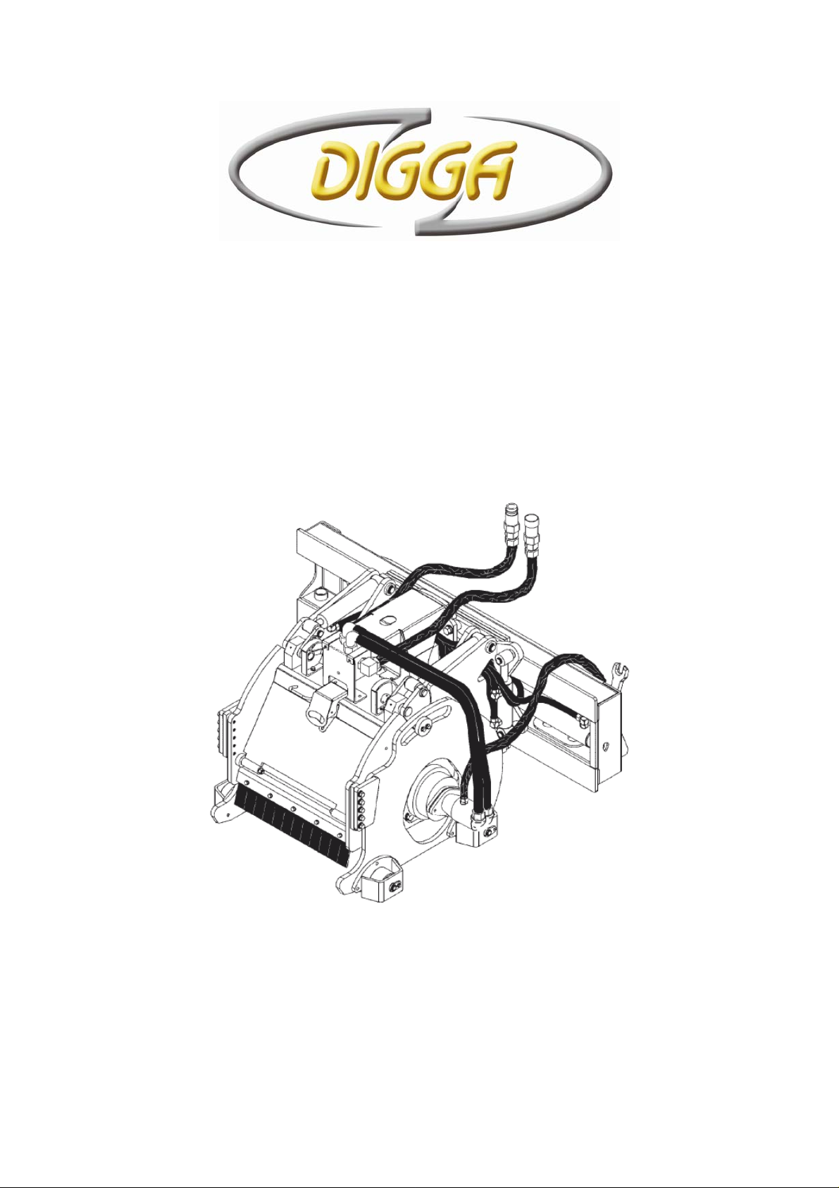
Profila
450 x 150 Road Profiler
Operator’s Manual
Page 2

This manual is the copyright property of:
DIGGA AUSTRALIA Pty Ltd
4 Octal Street, Yatala, Queensland, Australia
Phone: (07) 3807 3330 Fax: (07) 3807 1499
Int’l Phone: +61 7 3807 3330 Fax: +61 7 3807 1499
Web Site: www.digga.com
Manufacturers of Planetary Drives, Augers, Trenchers, Wear
Parts, Pallet Forks, Brooms, Aluminium Ramps, Cement Mixers,
Spreader Bars, etc.
E-mail: [email protected]
Page 3

1 Table of Contents
1 TABLE OF CONTENTS 1
2 TO THE PURCHASER 2
3 TECHNICAL SPECIFICATIONS 3
4 PREPARATION FOR USE 3
5 SAFETY 4
6 PRE-OPERATION 9
7 INSTALLATION INSTRUCTIONS 11
8 MAINTENANCE AND SERVICE 17
9 TROUBLESHOOTING 23
10 BOLT TORQUE SPECIFICATIONS 25
11 PARTS LIST 26
12 WARRANTY 29
Profila Operator’s Manual Table of Contents 1
Page 4

2 To the Purchaser
GENERAL COMMENTS
Congratulations on the purchase of your new DIGGA product! This product was
carefully designed and manufactured to give you years of dependable service. Only
minor maintenance (such as cleaning and lubricating) is required to keep it in top
working condition. Be sure to observe all safety precautions and maintenance
procedures as described in this manual.
ABOUT THIS MANUAL
This manual has been designed to help you do a better, safer job.
Read this manual carefully and become familiar with it's contents. Remember, never
let anyone operate this unit without reading the "Safety Precautions" and "Operating
Instructions" sections of this manual. (See Sections B and G respectively.)
Unless noted otherwise, right and left sides are determined from the position of the
operator when behind the product facing forward.
SAFETY ALERT SYMBOL
This is the "Safety Alert Symbol" used by this industry. This symbol
is used to warn of possible injury. Be sure to read all warnings
carefully. They are included for your safety and for the safety of
others working with your.
SERVICE
When servicing your product remember to use only manufacturer replacement parts.
Substitute parts may not meet the standards required for safe, dependable operation.
To facilitate parts ordering, record the model and serial number of your unit in the
space provided on this page. This information may be obtained from the identification
plate located on the product.
MODEL____________________________________
SERIAL NUMBER___________________________
DATE PURCHASED_________________________
The parts department needs this information to insure that you receive the correct
parts for your specific model.
Profila Operator’s Manual To the Purchaser 2
Page 5

3 Technical Specifications
DESCRIPTION
A. Overall Width…………………………………………….……………1000MM
B. Overall Height ……………………………………………….………..1050MM
C. Overall Length…………………………………………….…………..1050MM
D. Planing Width…………………………………………………………...400MM
E. Planing Depth……..………………………………………………….…150MM
Drum Diameter……………………………………………………………..700MM
Number of Picks ………………………………………...…………………60 approx
Weight ………………………………………………………………………950kgs
High Flow Requirement ..........................................85-150 LPM (22-40 GPM)
Operating Pressure.................................................17MPa (2500-3500 PSI)
4 Preparation for Use
The DIGGA Profila 150 receives its power from the Parent Machine through the
Auxiliary Valve circuit with Quick Release Couplers normally located on the machine
arms near the front.
Attaching points on the Profila 150 are the same as the bucket attaching points on
your machine.
Assemble Profila 150 if required. Refer Pg.4 Preparation for use.
Install DIGGA Profila 150 on the Skid Steer as you would a bucket. (See Skid Steer
Manual).
Hook up hoses to Auxiliary Hydraulics. Engine must be shut off.
To assure optimum motor life, run Hydraulic motor for one hour on approx. 1/3 RPM
before application of full load.
Ensure your machines flow and pressures do not exceed the maximum rated flow
and pressures of the Profila 150.(Refer Pg 3 To the Purchaser / Serial Tag)
If you are in any doubt contact your nearest DIGGA Dealer for
assistance
Profila Operator’s Manual Technical Specifications 3
Page 6

5 Safety
TAKE NOTE! THIS SAFETY ALERT SYMBOL FOUND THROUGHOUT THIS
MANUAL IS USED TO CALL YOUR ATTENTION TO INSTRUCTIONS INVOLVING
YOUR PERSONAL SAFETY OR OTHERS. FAILURE TO FOLLOW
THESE INSTRUCTIONS CAN RESULT IN INJURY OR DEATH.
THIS SYMBOL MEANS:
ATTENTION!
BECOME ALERT!
YOUR SAFETY IS INVOLVED!
SIGNAL WORDS
CAUTION with the safety messages. The appropriate signal word for each has been
selected using the following guidelines:
DANGER: Indicates an imminently hazardous situation, which if not avoided, will
result in death or serious injury. This signal word is to be limited to the most extreme
situations, typically for machine components which, for functional purposes,
cannot be guarded.
WARNING: Indicates a potentially hazardous situation, which if not avoided, could
result in death or serious injury, and includes hazards that are exposed when guards
are removed. It may also be used to alert against unsafe practices.
CAUTION: Indicates a potentially hazardous situation, which if not avoided, may
result in minor or moderate injury. It may also be used to alert against unsafe
practices.
SAFETY PRECAUTIONS
GENERAL INFORMATION
This section is composed of various warnings and safety tips. Read and learn all the
information in this section before you attempt to use your attachment. Also
: Note the use of signal words DANGER, WARNING, and
Profila Operator’s Manual Safety 4
Page 7

read your vehicle owner's manual before using your equipment. This knowledge will
help you operate your unit safely. Do not take this information lightly, it is
presented for your benefit and for the benefit of others working around you.
The "Safety Alert Symbol" (as described in Section A and at the beginning of Section
B) will be used throughout this manual. It will appear with the word DANGER
WARNING
covered. Take the time to read these messages as you come across them.
, or CAUTION, and a safety message pertaining to the specific topic being
,
TO THE OPERATOR
The primary responsibility for safety with the equipment falls to the operator. Make
sure that the equipment is operated only by responsible individuals with the proper
instruction. It is the skill, care, common sense, and good judgement of the operator
that will determine how efficiently and safely the job is performed. Know your
equipment before you start. Know its capabilities and how to operate all the controls.
Visually inspect your equipment before you start and never operate equipment that is
not in proper working order.
BEFORE YOU START
1. Read the entire loader and attachment operator's manuals
attempting to use the loader. This knowledge is necessary for safe operation.
before ever
2. Follow all safety decals
worn, damaged or illegible.
2. Do not paint over
equipment.
4. Know your equipment inside and out
know emergency shut down procedures.
5. Keep all stepping surfaces, pedals, and controls free from dirt, grease and
oil. Keep equipment clean to help avoid injury from a fall when getting on or off
equipment.
6. Use handholds and step plates when getting on/off . Failure to do so could cause a
fall.
7. Be alert to others in the work area.
will be working. Make sure no one is behind equipment.
8. Never take passengers on your equipment.
passenger.
9. Never try to board equipment while it is moving.
10. Turn off engine before performing maintenance.
performed with the machine lowered. If lift arms must be left raised for any reason,
use a positive lift arm lock to secure the arms in place. Serious damage or personal
injury could result from lift arms accidentally lowering.
, remove or deface any safety signs or warning decals on your
. Keep them clean and replace them if they become
. Know how to operate all controls and
Be sure others know when and where you
There is no safe place for a
All maintenance can be
11. Reduce speed when driving over rough terrain
overturning the loader.
12. Test all controls before you begin.
Profila Operator’s Manual Safety 5
, on a slope, or turning to avoid
Page 8

13. Do not smoke when refueling. Allow room in the gas tank for expansion.
Wipe up any spilt fuel. Secure cap tightly when done.
WORKING WITH THE ATTACHMENT
1. Never operate the unit without first reading and understanding the operator's
manual.
2. Operate the attachment only in daylight or sufficient artificial light.
3. Do not carry load with arms in the raised position.
the ground. Do not step off platform with load raised.
4. Check your work area and know where all utility lines are
underground electrical wires, cables, pipes, fence posts, gas lines, etc.
5. Never operate equipment while under the influence
drugs which could inhibit physical and/or mental capacity.
6. Do not exceed rated operating capacity, as machine may become unstable which
may result in loss of control.
7. Slow down before turning.
8. Always lower the loader arms to the ground
the key before getting off the unit.
Sharp turns on any terrain may cause loss of control.
, shut off the engine and remove
Always carry loads close to
. Avoid hitting
of alcohol, or prescription
TRANSPORTING THE ATTACHMENT
1. Follow all federal, state and local regulations when transporting the unit on public
roads.
2. Use extra care when loading or unloading the machine onto a trailer or truck.
MAINTENANCE
1. Never work on equipment while it is running.
2. Never make hydraulic repairs while the system is under pressure.
Injury or death could result.
3. Observe proper maintenance schedules
working order.
4 Always wear safety goggles or glasses when working on equipment.
5. Use a drift and hammer when pressing out pins to prevent the pin from shattering.
6. Use only manufacturer recommended replacement parts.
substandard in fit and quality.
and repairs to keep the unit in safe
Other parts may be
WARNING! Escaping fluid under pressure can have sufficient force to
penetrate the skin causing serious personal injury. Fluid escaping
from a very small hole can be almost invisible. Use a piece of
cardboard or wood, rather than hands to search for suspected
leaks.
Profila Operator’s Manual Safety 6
Page 9
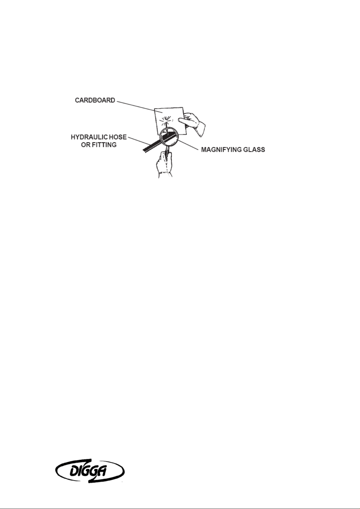
Keep unprotected body parts, such as face, eyes, and arms as far away as possible
from a suspected leak. Flesh injected with hydraulic fluid may develop gangrene or
other permanent disabilities.
If injured by injected fluid, see a doctor at once. If your doctor is not familiar with this
type of injury, ask him to research it immediately to determine proper treatment.
For additional safety information please see Risk Management booklet.
Profila Operator’s Manual Safety 7
Page 10

INTERNATIONAL SYMBOLS
Profila Operator’s Manual Safety 8
Page 11

6 Pre-Operation
GENERAL INFORMATION
The purpose of this manual is to assist in setting up, operating and maintaining your
DIGGA planer. Read it carefully. It furnishes information and instructions that will help
you achieve years of dependable performance.
Unless otherwise noted right and left are determined from the position of the
skidsteer operator sitting in the operator's seat facing forward.
Remember to read the "Safety Precautions" and "Operating Instructions" sections of
the manual BEFORE you attempt to install or use the planer.
NOTE: The illustrations and data used in this manual were current (according to the
information available to us) at the time of printing, however, we reserve the right to
redesign and change the Profilas as may be necessary without notification.
PREPARING THE VEHICLE
WARNING! Never let anyone operate this attachment without understanding all of
the "Safety Precautions" and "Operating Instructions" sections of this manual. (See
Section B and G respectively.)
Always choose hard, level ground to park the attachment on and set the brake so the
vehicle cannot roll.
SKID-STEER
The DIGGA 150 planers are designed for use on high flow skidsteers.
Profila and skid-steer compatibility is determined by the recommended lifting capacity
and hydraulic output of your skid-steer.
WARNING! Do NOT attach or operate any attachment that exceeds the
recommended lifting capacity of your skid-steer.
Skid-steers MUST be equipped with optional high flow, auxiliary boom hydraulics,
case drain and a multi-function electric control kit to run the Profila.
BEFORE OPERATION
The primary responsibility for safety with this equipment falls to the operator. Make
sure that the equipment is operated only by trained individuals that have read and
understand this manual. Don't hurry the learning process or take the unit for granted.
Practice the operation of your new equipment and become familiar with the controls
and the way it handles on your machine.
If there is any portion of this manual or function you do not understand, contact your
local authorized dealer or the manufacturer.
Profila Operator’s Manual Pre-Operation 9
Page 12
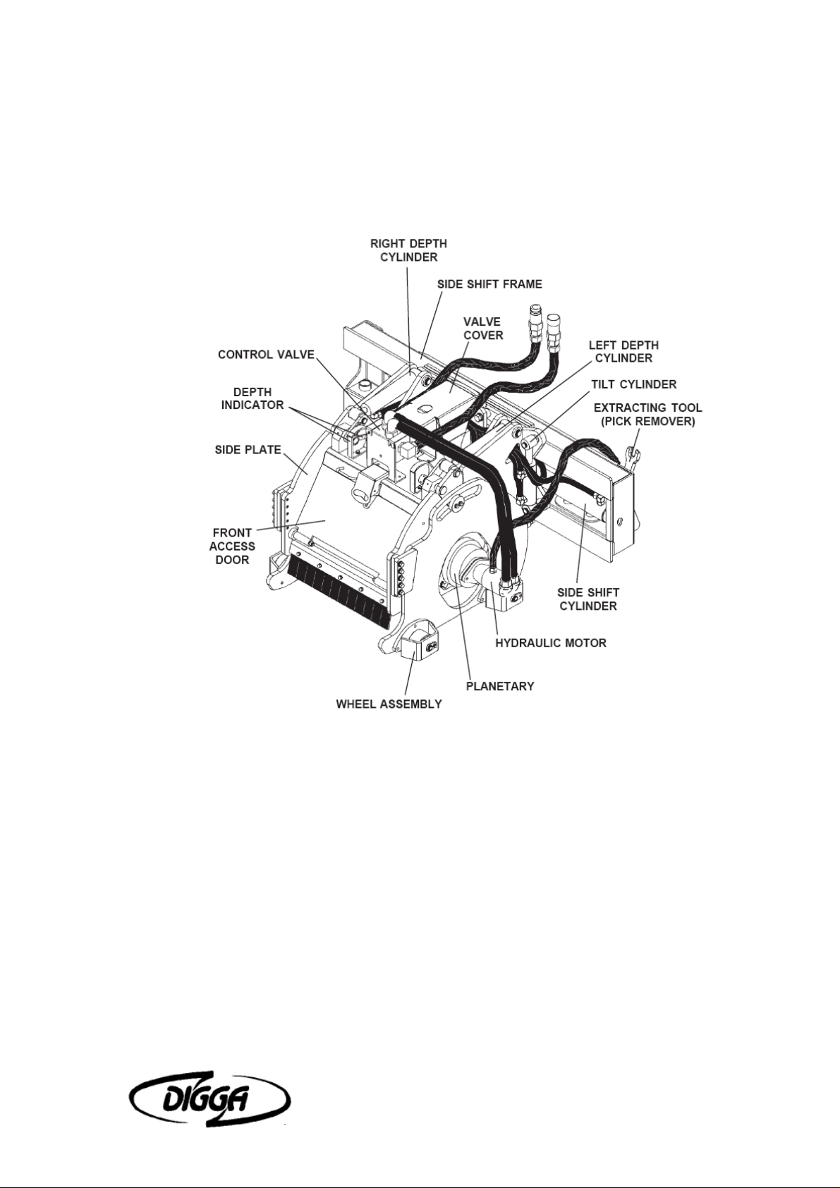
MAJOR NOMENCLATURE
Throughout this manual, reference is made to various attachment components.
The purpose of this section is to acquaint you with the various names of these
components. This knowledge will be helpful when reading through the manual or
when ordering service parts.
Profila Operator’s Manual Pre-Operation 10
Page 13

7 Installation Instructions
GENERAL INFORMATION
The following instructions will help you to mount your planer onto your
skidsteer loader. The planer uses the quick-attach system for ease of
installation. Therefore, if you know how to attach your loader bucket, attaching
the Profila should prove no problem.
Remember to read all safety warnings, decals and operating instructions
before operating the attachment. If there is any portion of this manual that you
do not understand, contact your dealer.
THE 150 PLANERS ARE DESIGNED FOR USE ON HIGH
FLOW HYDRAULIC SYSTEMS.
DO NOT ATTACH OR OPERATE ANY ATTACHMENT
THAT EXCEEDS THE RECOMMENDED LIFTING
CAPACITY OF YOUR SKIDSTEER.
INSTALLATION INSTRUCTIONS
1. Remove the shipping banding from around the planer and skid.
2. Remove any attachments from the front of the loader.
3. Following all standard safety practices and the instructions for installing
an attachment in your skid-steer operator's manual, install the planer
onto your skid-steer.
NOTE: It is important to make sure the locking mechanism on your
quick attach is engaged, therefore locking the attachment onto the
skid-steer.
4. Lower the unit to the ground and remove the key.
5. Relieve any pressure from the auxiliary hydraulic system and after
making sure that there is not any foreign matter on the hydraulic
couplers, connect the power and return couplers to the high flow
auxiliary hydraulic system of your skid-steer loader.
6. Connect the case drain coupler to the case drain on your skid-steer
loader.
7. Route the hoses in such a fashion as to avoid pinching or chafing.
BE SURE CASE DRAIN COUPLER IS COMPLETELY
ENGAGED.
IMMEDIATE HYDRAULIC MOTOR SEAL FAILURE AND
PLANETARY DAMAGE WILL OCCUR IF CASE DRAIN IS
Profila Operator’s Manual Installation Instructions 11
Page 14

NOT SUCCESSFULLY CONNECTED.
8. Connect the electrical wire harness from the Profila to the auxiliary
electrical connector on the front of the skid-steer (if so equipped). If
your skidsteer is not equipped with an electrical connector and you are
using the
9. DIGGA control handle, connect the wiring harness to the control handle
and place the control handle inside of the skid-steer operator's station.
Do not operate the Profila from outside of the skid-steer
operator's station.
10. Following all standard safety practices, start the skid-steer and run all
cylinders through their full cycle to purge any air from the system.
Check that all controls function in accordance with the operating control
decal.
11. If your planer is equipped with an optional water kit, install the female
coupler supplied to your water line coming from the water tank on the
skid-steer.
Connect the female coupler to the male coupler on the planer water kit.
Your planer is now installed and ready for operation.
DISCONNECT INSTRUCTIONS
1. Center the planer on the sideshift frame.
2. Adjust depth and tilt setting to "0".
3. Set Profila on a firm level surface.
4. Following Safety Shut Down Procedures; stop the engine and set the
parking brake. Relieve any pressure in the hydraulic lines.
5. Disconnect the power and return hoses from the auxiliary hydraulics.
6. Disconnect the electrical wire harness from the auxiliary electrical
connector or the DIGGA control handle and after turning the ball valve
to the shut off position disconnect the water line at the couplers.
7. Following all standard safety practices and the instructions for
disconnecting an attachment in your skid-steer operator's manual,
disconnect the planer from your skid-steer allowing the mounting
bracket to lower toward the ground as the skid-steer is disengaged.
8. Connect the hydraulic couplers on the attachment together to prevent
contaminants from entering the hydraulic system.
GENERAL INFORMATION
The DIGGA planer attaches to the toolbar/quick-attach mechanism of your
skid-steer loader. Due to this arrangement, thorough knowledge of the skid-
Profila Operator’s Manual Installation Instructions 12
Page 15
steer controls is necessary for machine operation. Read and understand your
skid-steer operator's manual for information regarding skid-steer operation
before attempting to use the planer.
Check the surface to be planed. The standard all purpose picks can be used
to mill both asphalt and concrete. There are optional concrete picks that are
recommended if the planer is to be used extensively for concrete. These picks
do not perform as well when milling asphalt, especially in warmer weather.
Review the job at hand and determine the required depth and tilt of the cut
and also the side shift position of the planer. Best performance is obtained
when the Profila is in the center position. Side shift should be used when
visibility is a determining factor such as milling around manholes or when
milling next to an obstacle such as a building.
NOTE: The optional wheel assemblies may be removed when distance is
a factor such as milling next to an obstacle or building.
OPERATING INSTRUCTIONS
1. Clear area of all bystanders.
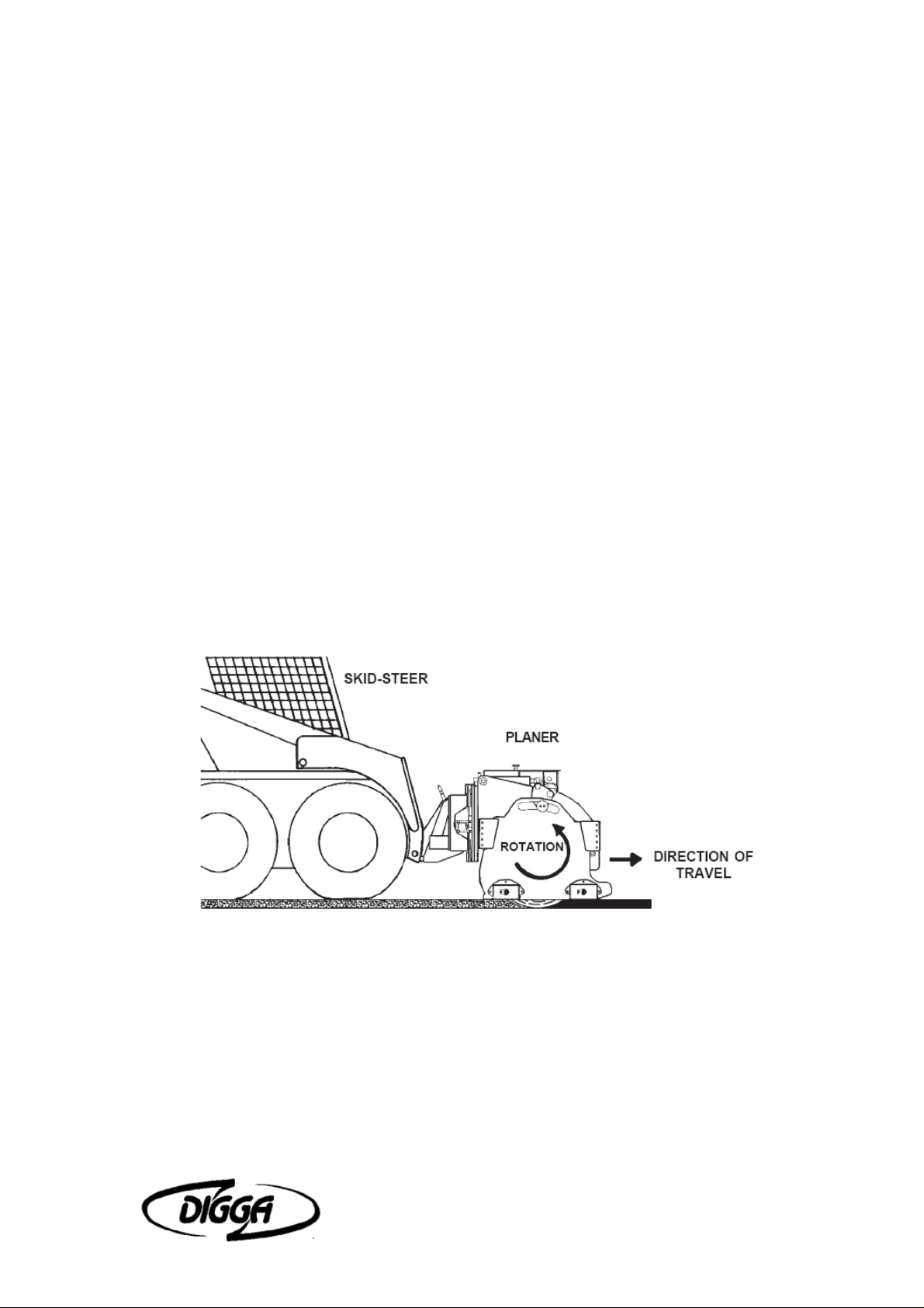
2. Lift the planer until the drum is off the ground and start planer rotation.
(Teeth at the bottom of the drum must be moving in the same forward
direction that the planer travels.)
NOTE: Mill only when the skid-steer is traveling forward. Do not operate
when traveling in reverse.
NOTE: Hydraulic cylinders tilt the planer, adjust the depth of both the
left and right side of the planer individually, and also shift the planer to
the left or right.
3. Increase engine RPM and with the drum turning you can make any
necessary adjustments to the side shift. Do not side shift the Profila during
milling operation. Once the desired side shift position has been achieved you
are ready to begin. The drum will not cut in a side to side motion. Tilt and
Depth control can both be activated during milling.
IMPORTANT: The drum MUST be turning to make any hydraulic
adjustment to the planer.
Profila Operator’s Manual Installation Instructions 13
Page 16

4. Position the planer at the desired starting point. Set the left and right depth
gauge to the desired depth mark on the planer. Maximum depth of each cut is
determined by the type of material, the horsepower of the skid-steer being
used and the size of the planer. It is recommended for maximum performance
that you start at approximately .75" to 50mm in concrete and 1.50" to 100mm
in asphalt.
5. With the engine at full RPM and the planer rolled back, lower the loader
arms completely down and slowly roll out the planer until the weight of the
planer is resting on the rear wheel assemblies. Continue to exert down
pressure by rolling the loader forward until the front wheels of the planer are
on the ground and the front wheels of the skid-steer are raised approximately
2-3 inches off the planing surface to assure sufficient pressure for stable
operation.
NOTE: It is recommended to try a sample cut until the desired depth is
achieved.
6. Slowly advance forward.
NOTE: If drum stalls you have been traveling too fast or cutting too
deep. Back out of the cut until the drum restarts (make necessary
adjustments) and then continue operation.
NOTE: If the drum tends to ride up out of the cut, decrease travel speed,
be sure the planer is level (front to back) and exert down pressure until
the planer is riding on the skids/wheel assemblies. For optimal cutting
and reduced vibration, maintain down pressure on the planer with all
four planer wheels on the ground when cutting.
NOTE: Avoid side to side movement while planing as this may cause
excessive drum wear or planetary failure.
7. When you have reached the end of the pass, stop the skid-steer and raise
the planer out of the cut. Reposition skid-steer for the next cut and repeat
steps 4, 5 & 6. If you are not starting a new cut, raise the planer and retract
the drum into the planer housing using the depth control cylinders. Do not
transport the planer with drum turning.
Periodic observation must be made of the
transmission oil temperature indicator when planing
with high flow hydraulic systems.
Depending on the ambient temperature and the duty
cycle of the machine, hydraulic oil may overheat.
If indicator comes on, shut off the Profila and allow
the skid-steer to idle until the temperature falls below
160° Fahrenheit.
If the system continues running hot it may be
necessary to clean any debris from the oil cooler and
radiator. Check engine air filter and also the hydraulic
oil level.
Profila Operator’s Manual Installation Instructions 14
Page 17
Continuous or excessive overheating may cause machine damage.
SPECIAL APPLICATIONS
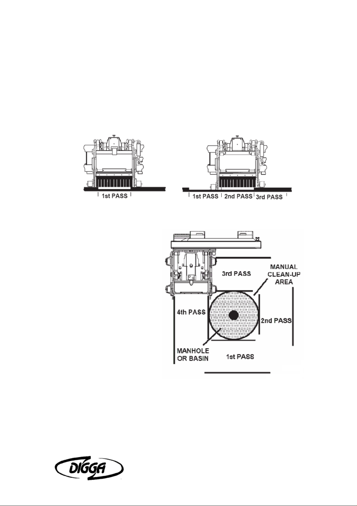
LARGE AREA
DIGGA'S independent depth control design allows for continuous milling.
Instead of planing pass 1, 3, 5 and then going back and resetting the planer
for passes 2 and 4, the DIGGA planer allows for individual depth control from
the operator's seat to enhance performance and continually mill large areas.
MILLING AROUND
MANHOLES
For best visibility when milling
around manholes it is
recommended that the planer
be shifted to the right. The
planer is not designed to mill
around tight corners, therefore
it is recommended that four to
six passes be made on each
side of the manhole. NOTE:
The more passes the less
amount of manual clean-up
required.
DEEP CUTS
To achieve a deep cut the width of the drum, make the first cut at the
recommended depth for the material being milled and then reposition the
planer at the beginning of the pass and reset for double the recommended
depth. Example: Make the first cut with the depth controls set at 100mm and
then set the depth control at 100mm for the second pass and so on and so
forth until the desired depth is obtained.
Profila Operator’s Manual Installation Instructions 15
Page 18
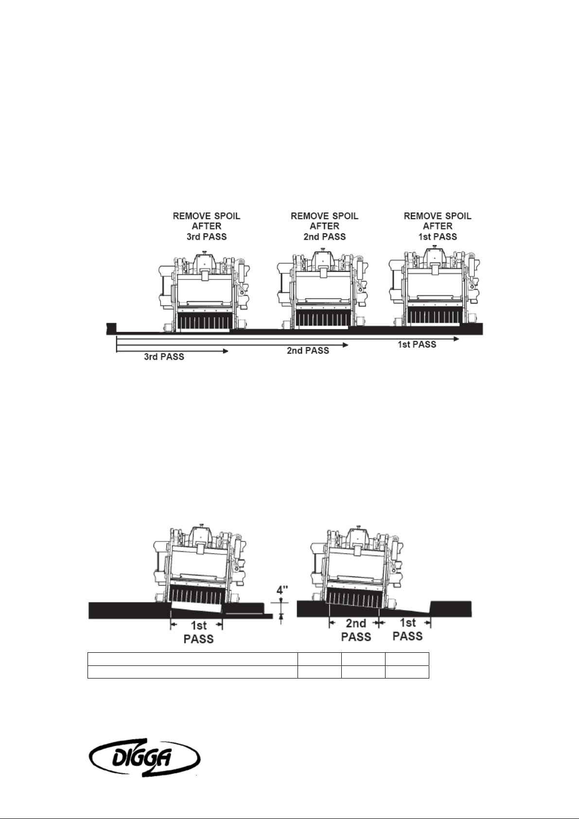
To achieve a 150mm cut of a large area it is recommended to cut the entire
area at the recommended depth and then clear the spoil from the area before
making the second cut.
Removing the spoil between cuts will enhance the productivity of the planer
and maintain an even cut.
If trying to achieve a critical cutting depth it is recommended that the spoil
from one cut be cleared away before making another pass. This will eliminate
the possibility of the planer riding on and off the spoil and creating an uneven
surface.
MILLING TAPER CUTS
When adding to or joining new paved surfaces to existing paving, a taper cut
may be required at the interacting joints so the new paving would appear
seamless. See the chart below for the angle of cut per size of Profila.
Example: To achieve a taper cut from 0 to 100mm over a 1200mm distance with
a 600mm wide Profila it is recommended that you set one side of the planer at
100mm and the other at 100mm and the tilt set at 4° for the first pass. Then
make a second pass with both sides of the planer set at 0mm and the tilt still at
4°.
OFFSET 25mm 50mm 75mm
ANGLE OF CUT (degrees) 2 4 6
Profila Operator’s Manual Installation Instructions 16
Page 19

8 Maintenance and Service
GENERAL INFORMATION
Economical and efficient operation of any machine is dependent upon regular
and proper lubrication of all moving parts with a quality lubricant. Neglect
leads to reduced efficiency, wear, breakdown and needless replacement of
parts.
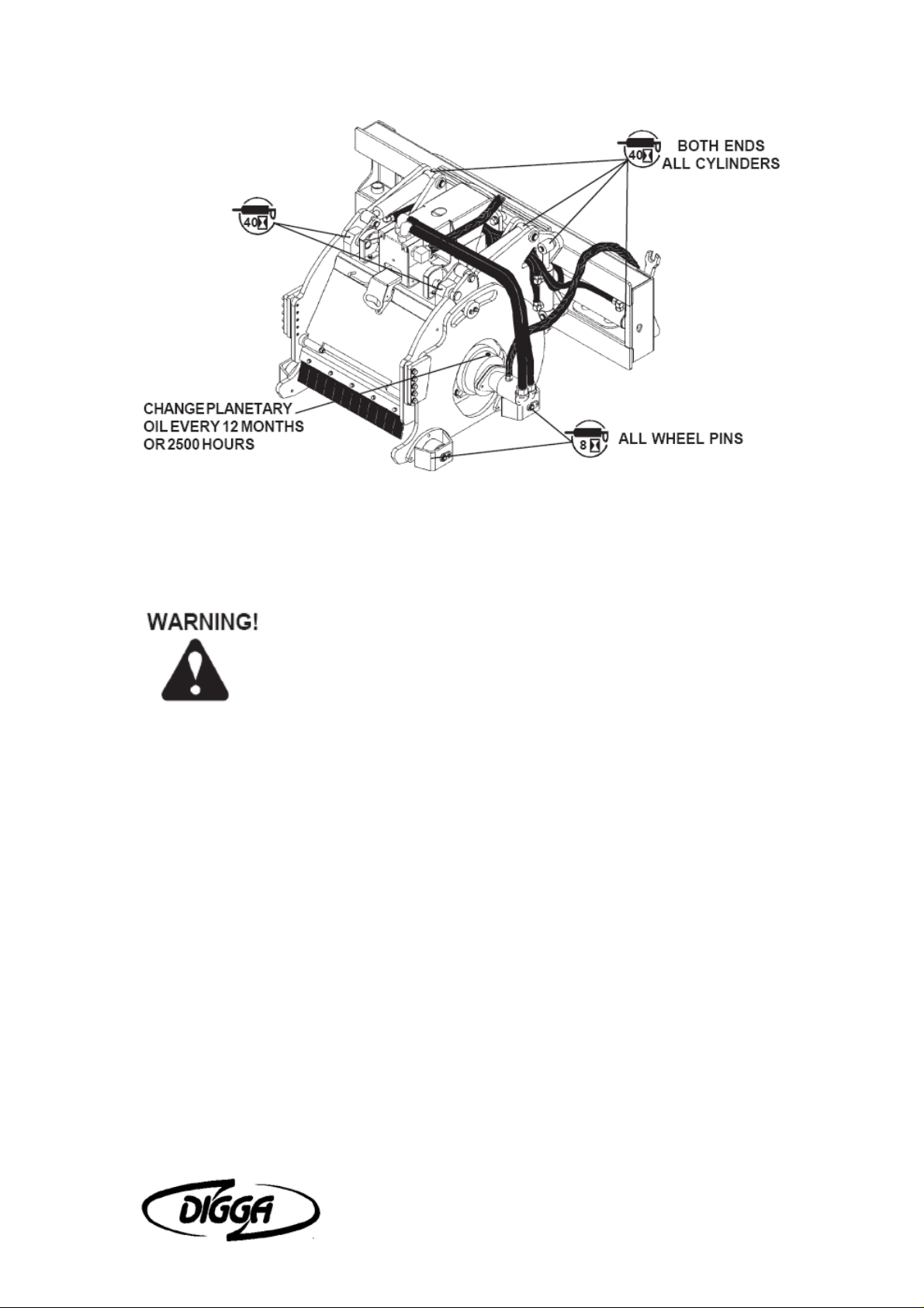
All parts provided with grease fittings should be lubricated as indicated. If any
grease fittings are missing, replace them immediately. Clean all fittings
thoroughly before using the grease gun.
IMPORTANT: Avoid excessive greasing. Dirt collects on exposed grease
and greatly increases wear. After greasing, wipe off excessive grease
from fittings.
LUBRICATION SYMBOLS
The following symbols are used on the lubrication diagram below. It is
reproduced here with its meaning for your convenience.
Lubricate daily or every 8 hours of operation, whichever comes last,
with SAE Multi-Purpose Lubricant or equivalent SAE Multi-Purpose
type grease.
Lubricate weekly or every 40 house of operation, whichever comes
last, with SAE Multi-Purpose Lubricant or equivalent SAE MultiPurpose type grease.
CAUTION! SHUT OFF ENGINE BEFORE LUBRICATING
EQUIPMENT.
The planer planetary is a sealed unit. If there is any sign of oil leaks
please contact your nearest DIGGA dealer before carrying out any repairs, as
there can be other causes for seal leaks. The planetary uses the Gear Oil
(Castrol SP 320) for lubrication of gears and bearings. The unit holds
approximately 2 quarts of gear oil.
The planetary gear oil should be drained and replaced after the first 8 months
of use. Thereafter every 12 months or 2500 hours - whichever comes first.
Profila Operator’s Manual Maintenance and Service 17
Page 20
GENERAL INFORMATION
Regular maintenance is the key to long equipment life and safe operation.
Maintenance requirements have been reduced to an absolute minimum. However it
is very important that these maintenance functions be performed as described below.
Never do any maintenance to the planer while it is running.
Exercise the MANDATORY SAFETY SHUTDOWN PROCEDURE
BEFORE working on or around the planer.
DAILY
• Check to be sure case drain coupler is completely engaged.
• Check skid-steer hydraulic system to ensure an adequate level of hydraulic oil.
• Check all hardware and tighten if necessary. See Section "O" for Bolt Torque
Specifications.
• Check hydraulic system for hydraulic leaks.
• Check for missing or illegible Safety / Warning Decals.
• Check picks for freedom of rotation, flat spots and wear. Replace worn or missing
picks or any picks that are not rotating freely or have flat spots.
• Visually inspect the machine for worn parts or cracked welds and repair as
necessary.
• Lubricate grease fittings on Wheel pivot pins.
EVERY 40 HOURS
• Lubricate grease fittings on cylinder ends and front of planer.
Profila Operator’s Manual Maintenance and Service 18
Page 21
EVERY 2500 HOURS OR 12 MONTHS
• Change gear oil in planetary.
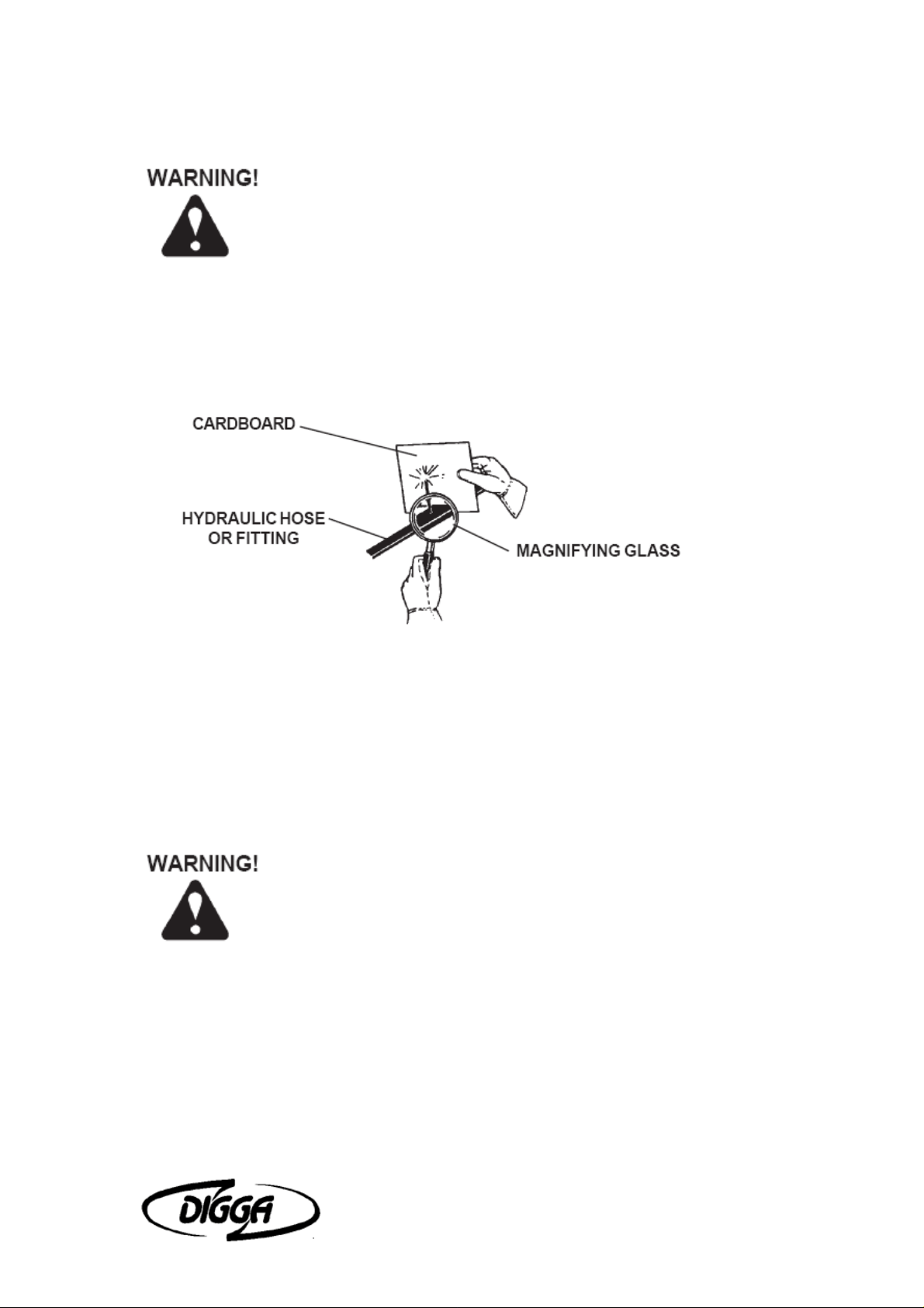
Escaping fluid under pressure can have sufficient force to
penetrate the skin causing serious personal injury. Fluid escaping
from a very small hole can be almost invisible. Use a piece of
cardboard or wood, rather than hands to search for suspected
leaks.
Keep unprotected body parts, such as face, eyes, and arms as far away as possible
from a suspected leak. Flesh injected with hydraulic fluid may develop gangrene or
other permanent disabilities.
If injured by injected fluid, see a doctor at once. If your doctor is not familiar with this
type of injury, ask him to research it immediately to determine proper treatment.
IMPORTANT: When replacing parts use only factory approved replacement parts.
Manufacturer will not claim responsibility for use of unapproved parts or accessories
and/or other damages as a result of their use.
PICK REPLACEMENT
Picks should be replaced if you are changing to a different application pick, they are
broken, worn, flat spot or are seized in the pick holder and do not rotate freely.
Always wear safety glasses with side shields when striking metal.
Failure to heed could result in serious injury to the eyes or other
parts of the body.
Do all pick maintenance through access door.
DO NOT attempt to check the picks with the planer in a raised
position without first blocking the planer. Before exercising the MANDATORY
SAFETY SHUTDOWN PROCEDURE find an elevated surface to set the
planer on or have a second person block the planer in place before shutting
down the machine.
1. Open front access door.
2. Rotate the drum until the pick to be removed is conveniently accessible.
3. Hold the extracting tool (pick puller) in one hand and place the jaws in the groove
of the pick, with the offset handle pointing away from the pick holder.
Profila Operator’s Manual Maintenance and Service 19
Page 22
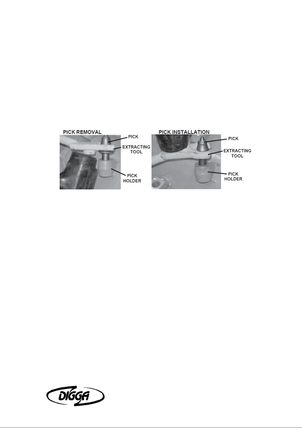
4. Using a lead hammer or rubber-headed mallet, hit the raised pad on the tool until
the pick starts to move. Continue tapping until the pick is removed.
5. Insert the new pick into the jaws of the extracting tool (pick puller) so that the
raised pad of the tool is pointing in the same direction as the pick point.
6. Position the new pick in the pick holder on the drum and with a lead hammer or
rubber-headed mallet, hit the raised pad of the tool to start the pick into the pick
holder. (Clean out any foreign material from the pick holder before installing the new
pick.)
7. Once the pick is started into the pick holder strike the tool pad one strong blow to
pop the pick into the holder.
The pick is properly seated when its shoulder is against the face of the pick holder.
Check to be sure the pick rotates freely.
Profila Operator’s Manual Maintenance and Service 20
Page 23
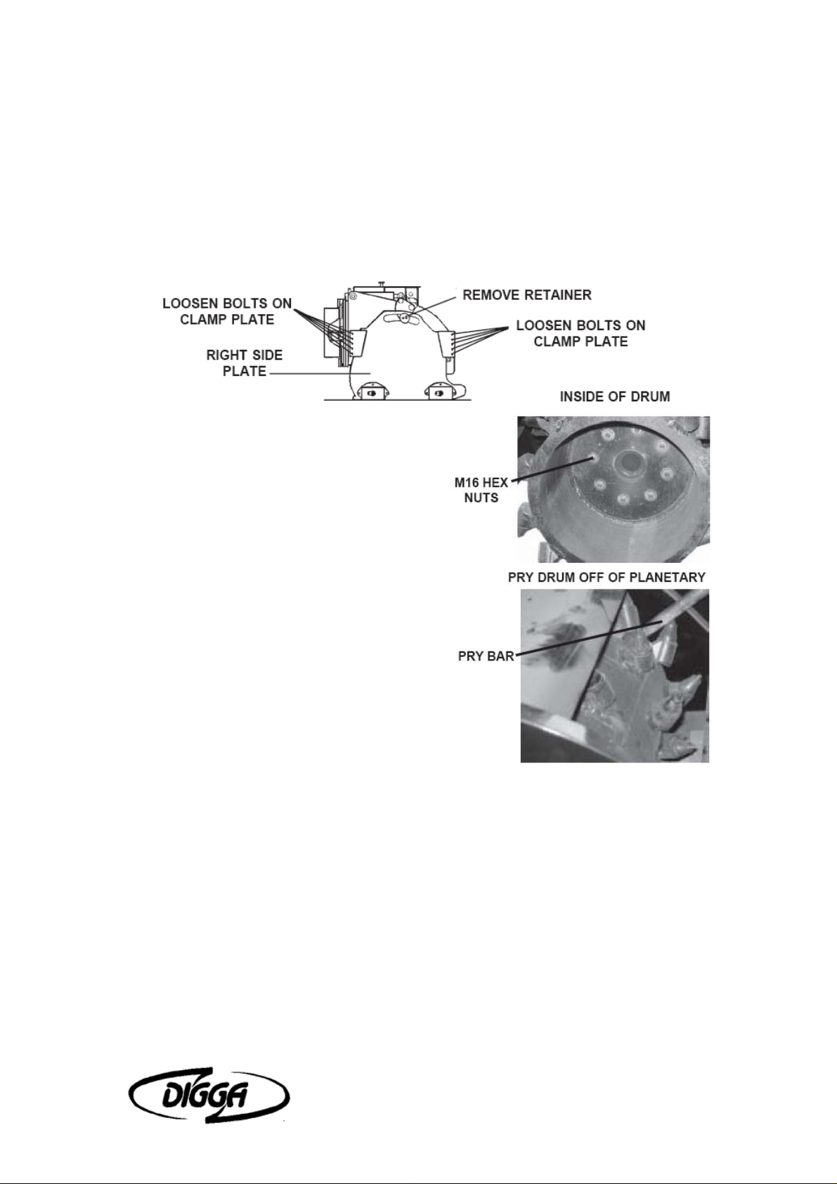
CHANGING THE DRUM
Due to the weight of the unit, place the planer in a convenient location with a hoist
available for lifting the planer off the drum.
1. Remove the right side plate by first removing the two bolts in the retainer and then
loosen the ten .50" bolts on the clamp plates. Slide the right side plate off.
2. Remove the eight M16 hex nuts securing
the drum to the planetary.
3. Using a pry bar, pry the drum off of the
planetary and slide out until the drum clears
the planetary.
lift the planer off of the drum.
4. Install the new drum by positioning it over
the studs on the planetary and installing the
existing M16 hex nuts using Locktite 271
(Red) and torquing to 155 ft. lbs.
5. Reinstall the right side plate.
Profila Operator’s Manual Maintenance and Service 21
Page 24
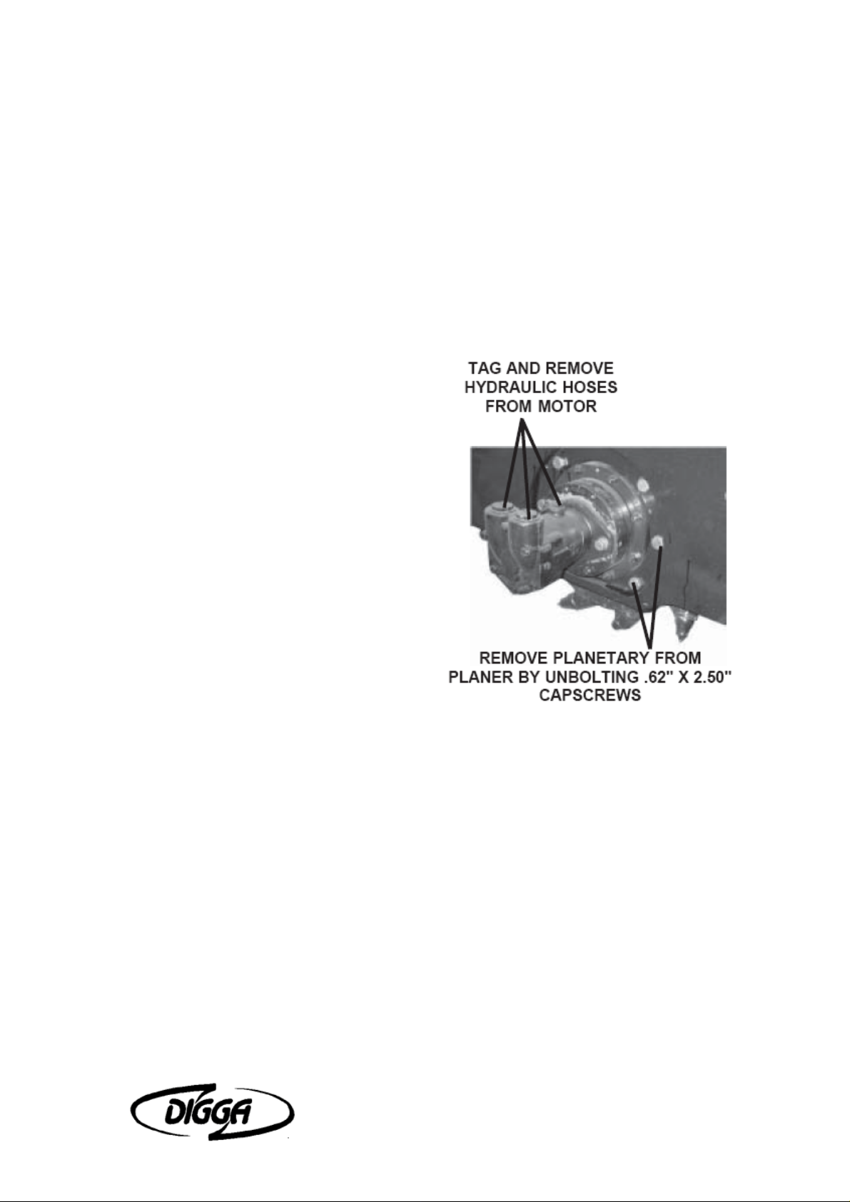
CHANGING THE PLANETARY
To gain access to the planetary the drum must first be removed. Follow the above
procedure for removing the drum.
1. Tag and disconnect the power and return hoses along with the case drain hose
from the hydraulic motor and plug the motor ports to prevent contaminates from
entering the hydraulic system.
2. Remove the .6100mm bolts securing the planetary to the planer and remove the
planetary.
3. Check to be sure the new planetary is
filled with oil. If not, fill with approximately 2
quarts of Castrol SP 320 gear oil.
4. Remove the hydraulic motor from the
planetary. Scrape any silicone from the
hydraulic motor and apply new RV 10
silicone to the motor to seal the connection
between the motor and the planetary.
Bolt the hydraulic motor onto the new
planetary using the existing hardware.
5. Position the new planetary into the
planer housing and reinstall the .6100mm
capscrews, flat washers and lock nuts.
Check to ensure that the hydraulic motor is
in the correct position with the ports turned
up. Torque to specification
6. Reinstall the drum as described in
"CHANGING THE DRUM".
7. Re-connect the hydraulic hoses and fittings to the motor.
CHANGING HYDRAULIC MOTOR
1. Position the planer on its side or in such a fashion that the planetary oil will not
leak out when replacing the motor.
2. Tag and disconnect the power and return hoses along with the case drain hose
from the hydraulic motor.
3. Remove the capscrews securing the motor to the planetary.
4. Scrape the mating surface of the planetary, removing all existing silicone, to
prepare it for the new motor.
5. Apply new RV 10 silicone to the motor to seal the connection between the motor
and the planetary. Bolt the new hydraulic motor onto the planetary using the existing
hardware. (Check to ensure that the hydraulic motor is in the correct position with the
ports turned up.) Torque to specification
6. Re-connect the hydraulic hoses and fittings to the motor.
Profila Operator’s Manual Maintenance and Service 22
Page 25
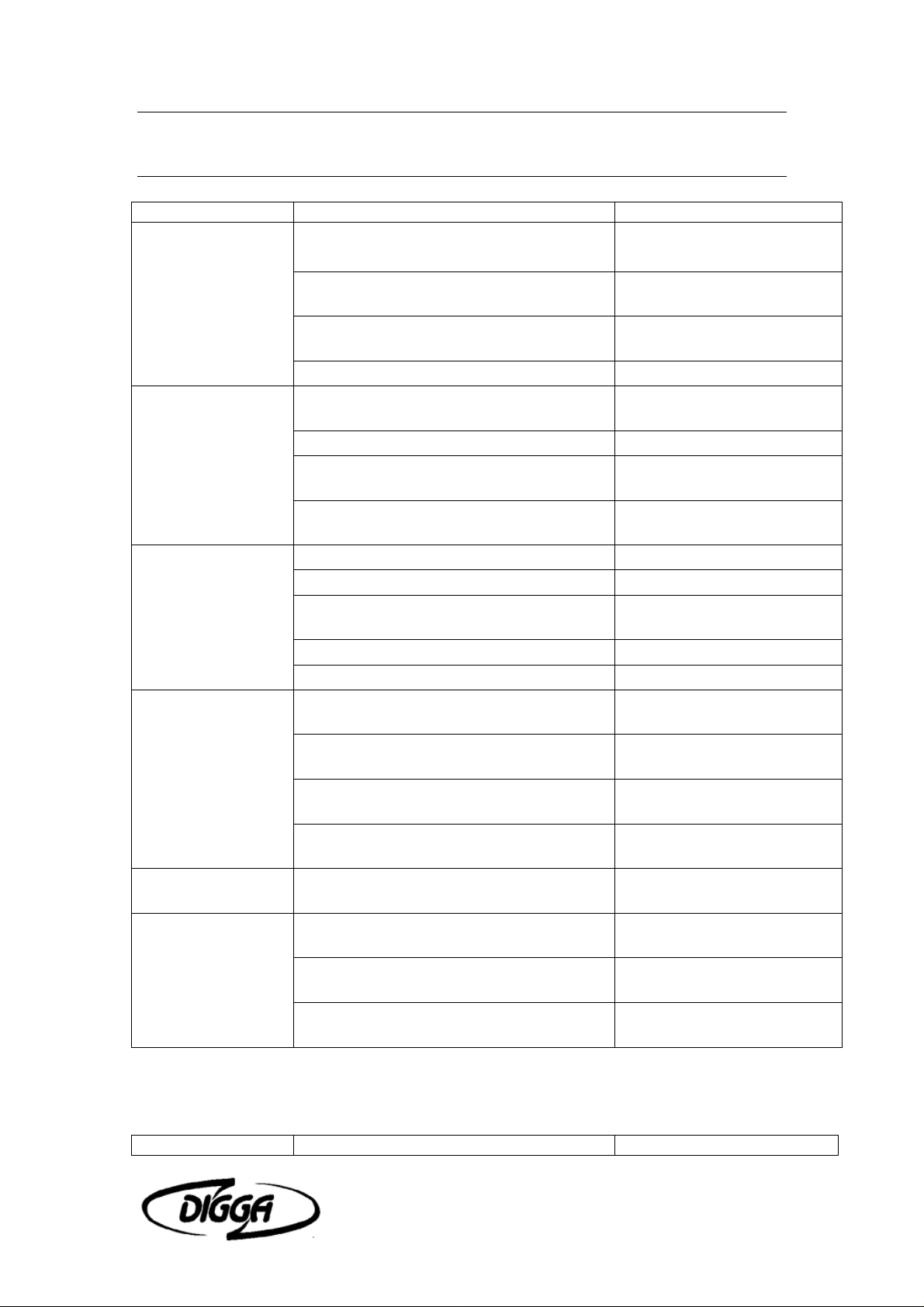
9 Troubleshooting
PROBLEM POSSIBLE CAUSE POSSIBLE REMEDY
Motor on the
planer will not
operate
Drum rotates
sluggishly
Leaking Oil
Insufficient power Insufficient hydraulic flow from the skid-
Drum rotates in the
wrong direction
Excessive
vibration during
planing operation
Auxiliary hoses not hooked up to the
skid-steer
Obstruction in hydraulic lines Remove obstruction and
Hydraulic motor damaged or seals
blown
Skid-steer auxiliary valve not engaged Engage auxiliary valve
Insufficient hydraulic flow from the skid-
steer
Damaged quick coupler Replace if necessary
Hydraulic motor damaged or seals
blown
Oil filter on skid-steer is dirty. Refer to skid-steer's owners
Loose or damaged hydraulic line Tighten or replace.
O-Rings on fittings damaged or blown Replace if necessary
Hydraulic motor damaged or seals Call Digga service
Fittings loose or damaged Tighten or replace
Cylinder seals damaged Replace cylinder seals
steer
Relief valve setting adjusted too low Refer to skid-steer's owners
Hydraulic motor damaged or seals
blown
Oil filter on skid-steer is dirty Refer to skid-steer's owners
Hoses from the valve to the motor
incorrectly connected
Picks are worn or broken Visually inspect the picks
Picks contain flat spots or are not
rotating freely
Insufficient down force due to incorrect
operating procedure
Engage Couplers
replace if necessary
Call Digga service
department for instructions
Refer to skid-steer's owners
manual
Call Digga service
department for instructions
manual.
department for instructions
Refer to skid-steer's owners
manual
manual
Call Digga service
department for instructions
manual
Switch hoses at the motor
end
and replace as necessary
Visually inspect the picks
and replace as necessary
Refer to the Operating
section of this manual
PROBLEM POSSIBLE CAUSE POSSIBLE REMEDY
Profila Operator’s Manual Troubleshooting 23
Page 26

Excessive oil
temperature
Hydraulic oil level too low. Refer to skid-steer's
owners manual
Obstruction in hydraulic lines Remove obstruction and
replace if necessary
A Hydraulic
cylinder not
operating
Hydraulic cylinders
only operating in
one direction
Hydraulic oil or oil filter in skid-steer is
dirty
Relief valve setting adjusted too low Refer to skid-steer's
Couplers not engaged Engage couplers
Insufficient hydraulic flow from the skid-
steer
Cylinder rod bent Visually inspect the
Cylinder seals damaged Replace cylinder seals
Obstruction in hydraulic lines Remove obstruction and
Contaminants in the hydraulic system
and solenoid valve
Damaged electrical wiring.
Refer to skid-steer's
owners manual
owners manual
Refer to skid-steer's
owners manual
cylinder for damage
replace if necessary
Remove spool from
solenoid valve and check
for foreign material. Clean
or replace. Also check
seals for damage. Replace
if necessary
Test and replace if
necessary.
All hydraulic
cylinders not
functioning
Solenoid valve spool bent Replace spool
Nut on Solenoid valve too tight Loosen nut
Blown fuse on skid-steer Refer to skid-steer's
owners manual
Damaged electrical wiring Test and replace if
necessary
Solenoid valve spool bent Replace spool
Nut on Solenoid valve too tight Loosen nut
Profila Operator’s Manual Troubleshooting 24
Page 27
10 Bolt Torque Specifications
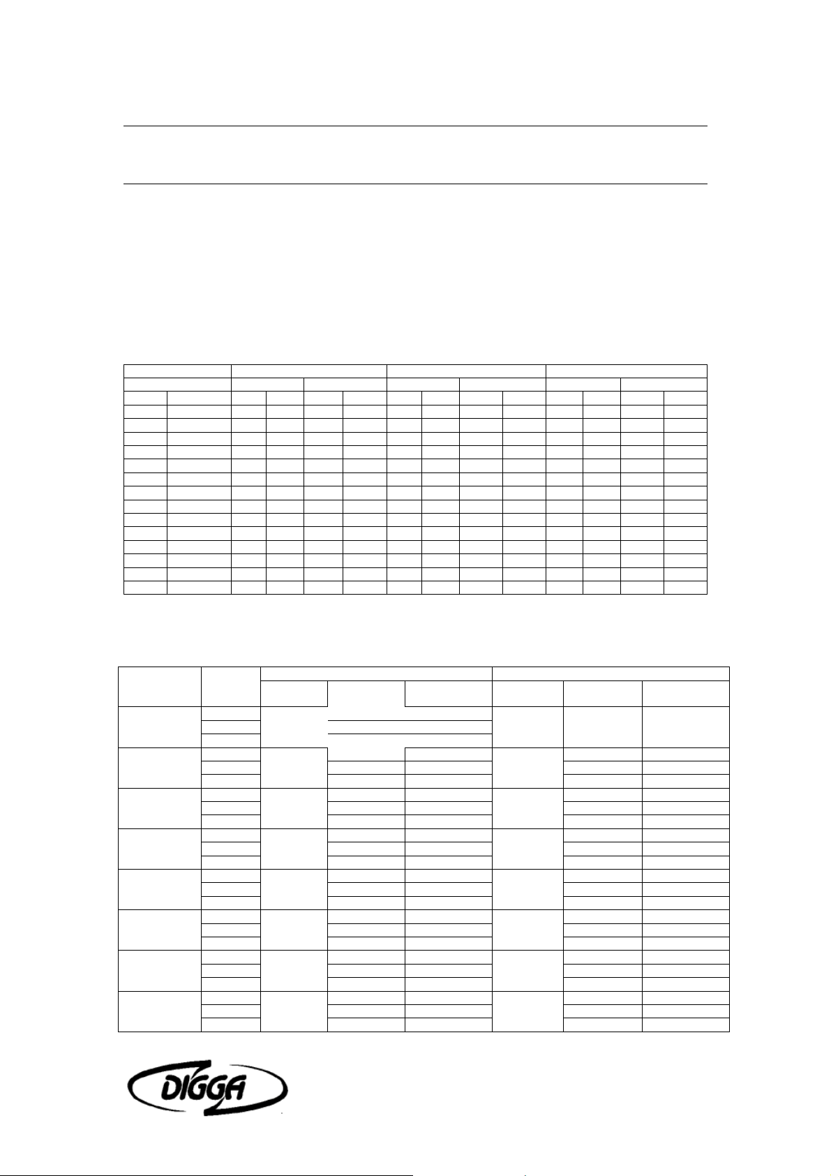
GENERAL TORQUE SPECIFICATION TABLE
Use the following torques when special torques are not given. These values apply to
fasteners as received from suppliers, dry, or when lubricated with normal engine oil.
They do not apply if special graphited or moly disulphide greases or other extreme
pressure lubricants are used. This applies to all METRIC, UNF and UNC threads.
Remember to always use grade five or better when replacing bolts.
TORQUE TORQUE TORQUE
Bolt Size Pounds Feet Newton-Meters Pounds Feet Newton-Meters Pounds Feet Newton-Meters
Inches Millimeters Min. Max. Min. Max. Min. Max. Min. Max. Min. Max. Min. Max.
1/4 6.35 5 6 6.8 8.13 9 11 12.2 14.9 12 15 16.3 30.3
5/16 7.94 10 12 13.6 16.3 17 20.5 23.1 27.8 24 29 32.5 39.3
3/8 9.53 20 23 27.1 31.2 35 42 47.5 57.0 45 54 61.0 73.2
7/16 11.11 30 25 40.7 47.4 54 64 73.2 86.8 70 84 94.9 113.9
1/2 12.70 45 52 61.0 70.5 80 96 108.5 130.2 110 132 149.2 179.0
9/16 14.29 65 75 88.1 101.6 110 132 149.2 179.0 160 192 217.0 260.4
5/8 15.88 95 105 128.7 142.3 150 180 203.4 244.1 220 264 298.3 358.0
3/4 19.05 150 185 203.3 250.7 270 324 366.1 439.3 380 456 515.3 618.3
7/8 22.23 160 200 216.8 271.0 400 480 542.4 650.9 600 720 813.6 976.3
1 25.40 250 300 338.8 406.5 580 696 786.5 943.8 900 1080 1220.4 1464.5
1-1/8 25.58 - - - - 800 880 1084.8 1193.3 1280 1440 1735.7 1952.6
1-1/4 31.75 - - - - 1120 1240 1518.7 1681.4 1820 2000 2467.9 2712.0
1-3/8 34.93 - - - - 1460 1680 1979.8 2278.1 2380 2720 3227.3 3688.3
1-1/2 38.10 - - - - 1940 2200 2630.6 2983.2 3160 3560 4285.0 4827.4
• Thick Nuts must be used with Grade 8 bolts
METRIC BOLT TORQUE SPECIFICATIONS
Size of
Screw
M6
M8
M10
M12
M14
M16
M18
M20
Grade
No
5.6
10.9 7.2-10 9.8-13.6
5.6
8.8 17-22 23-29.8 19-27 25.7-36.6
10.9 20-26 27.1-35.2 22-31 29.8-42
5.6
8.8 34-40 46.1-54.2 35-47 47.4-63.7
10.9 38-46 51.5-62.3 40-52 54.2-70.5
5.6
8.8 51-59 69.1-79.9 56-68 75.9-92.1
10.9 57-66 77.2-89.4 62-75 84-101.6
5.6
8.8 81-93 109.8-126 90-106 122-143.6
10.9 96-109 130.1-147.7 107-124 145-168
5.6
8.8 116-130 157.2-176.2 120-138 162.6-187
10.9 129-145 174.8-196.5 140-158 189.7-214.1
5.6
8.8 150-168 203.3-227.6 177-199 239.8-269.6
10.9 175-194 237.1-262.9 202-231 273.7-313
5.6
8.8 186-205 252-277.8 206-242 279.1-327.9
10.9 213-249 288.6-337.4 246-289 333.3-391.6
Coarse Thread Fine Thread
Pitch
(mm)
1.0
1.25
1.5
1.75
2.0
2.0
2.0
2.5
Pounds
Feet
3.6-5.8 4.9-7.9
7.2-14 9.8-19
20-25 27.1-33.9
28-34 37.9-46.1
49-56 66.4-75.9
67-77 90.8-104.3
88-100 119.2-136
108-130 146.3-176.2
NewtonMeters
Pitch (mm) Pounds Feet
8.8 5.8-9.4 7.9-12.7
1.0
1.25
1.25
1.5
1.5
1.5
1.5
NewtonMeters
12-17 16.3-23
20-29 27.1-39.3
31-41 42-55.6
52-64 70.5-86.7
69-83 93.5-112.5
100-117 136-158.5
132-150 178.9-203.3
Profila Operator’s Manual Bolt Torque Specifications 25
Page 28
11 Parts List
Profila Operator’s Manual Parts List 26
Page 29

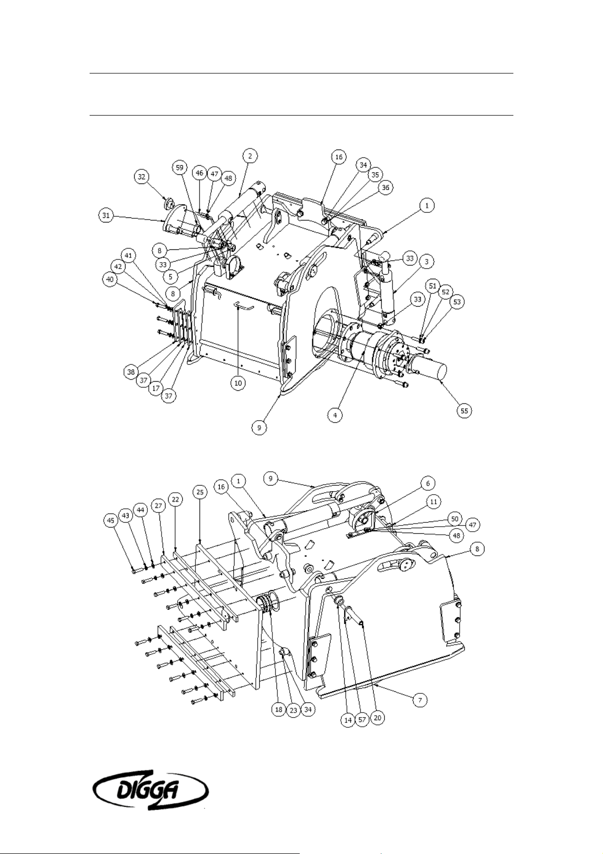
ITEM QTY PART NUMBER DESCRIPTION
1 1 CP-010000 Full Assembly
2 2 BC001-200 Bucket Cylinder Assembly
3 1 BC001-150 Bucket Cylinder Assembly
4 1 100265 Road Profiler Gearbox
5 2 CP-006000 Depth Indicator Assy
6 2 CP-004000 Depth Indicator Assy
7 1 SRPD-10 Road Profiler Drum
8 1 CP-001100 Height Adjuster Assembly
9 1 CP-001200 Depth Adjuster Plate Assy
10 1 CP-005000 Front Door Assy
11 2 Latch Assembly
12 2 CP-000060 Bush
13 2 CP-000180 Depth Pivot Block
14 4 CP-000240 Clevis Bush
15 2 CP-000290 Shackle Plate
16 1 CP-000300 Angle Indicator Plate
17 4 CP-000310 Spacer Shim
18 1 CP-000340 Bearing
19 1 CP-000360 Tilt Cylinder Pin
20 2 CP-000380 Pivot Pin
21 1 CP-000400 Guide Plate
22 2 CP-000440 Clamping Bar
23 4 CP-000450 Spacer
24 1 CP-000430 Pivot Retainer Plate
25 1 CP-000410 Mounting Plate
26 1 CP-000460 Stub Shaft
27 2 CP-000470 Clamping Bar
28 1 CP-000420 Pivot Pin
29 2 CP-003010 Pivot Pin
30 2 CP-003020 Cylinder Pivot
31 2 CP-003030 Level Adjustor Plate
32 2 CP-003040 Cam Roller
33 4 ISO 4032 - M20 Hex Nut
34 4 ISO 4017 - M20 x 70 Hex-Head Bolt
35 4 ISO 7091 - ST 20 - 100 HV Washer
36 4 ASME B18.21.1 - 13/16 Helical Spring Lock Washer
37 8 CP-000090 Spacer Bar
Profila Operator’s Manual Parts List 27
Page 30

38 4 CP-000110 Depth Plate Guide Plate
39 1 CP-005050 Cover Hinge Pin
40 12 ANSI B18.2.3.5M - M14 x 2 x 60 Hex Bolt
41 12 ANSI B18.22 M - 14 N Plain Washer
42 12 ASME B18.21.1 - 9/16 Helical Spring Lock Washer
43 14 ASME B18.21.1 - 1/2 Helical Spring Lock Washer
44 12 ANSI B18.22 M - 12 N Plain Washer
45 12 ANSI B18.2.3.5M – M12 x 1.75 x 50 Hex Bolt
46 4 ANSI B18.2.3.5M – M10 x 1.5 x 55 Hex Bolt
47 14 ANSI B18.22 M - 10 N Plain Washer
48 8 ASME B18.21.1 - 7/16 Helical Spring Lock Washer
49 4 ANSI B18.2.4.2M - M10 x 1.5 Hex Nut - Style 2 <= M16
50 4 ANSI B18.2.3.5M - M10 x 1.5 x 35 Hex Bolt
51 6 ANSI B18.3.1M - M16x2 x 70 Socket Head Cap Screw Metric
52 12 ANSI B18.22 M - 16 N Plain Washer
53 6 ASME B18.21.1 - 11/16 Helical Spring Lock Washer
54 6 ANSI B18.2.4.2M - M16 x 2 Hex Nut - Style 2 <= M16
55 1 EATON 74315 & 74318 Sae B Motor Mount Flange
56 2 ANSI B18.3 - 1/2 - 13 – 1 1/4 Hexagon Socket Head Cap Screw
57 2 CP-000210
58 2 ANSI B18.2.3.5M - M10 x 1.5 x 30 Hex Bolt
59 2 CP-003050 Wear Ring
Profila Operator’s Manual Parts List 28
Page 31

12 Warranty
All new Digga products are warranted to be free from defects in materials or
workmanship which may cause failure under normal usage and service when used
for the purpose intended.
In the event of failure within twelve (12) months from initial retail sale, lease or rental
date (excluding cable, ground engaging parts such as sprockets, digging chain,
bearings, teeth, tamping and demolition heads, blade cutting edges, pilot bits, auger
teeth, auger heads & broom bristles), if after examination, Digga determines failure
was due to defective material and/or workmanship, parts will be repaired or replaced.
Digga may request defective part or parts be returned prepaid to them for inspection
at their place of business at Stapylton, Queensland, or to a location specified by
Digga.
Any claims under this warranty must be made within fifteen (15) days after the Buyer
learns of the facts upon which such claim is based. All claims not made in writing and
received by Digga within the time period specified above shall be deemed waived.
THIS WARRANTY IS IN LIEU OF ALL OTHER WARRANTIES EXPRESSED OR
IMPLIED AND THERE ARE NO WARRANTIES OF MERCHANTABILITY OR OF
FITNESS FOR A PARTICULAR PURPOSE. IN NO EVENT SHALL DIGGA BE
LIABLE FOR CONSEQUENTIAL OR SPECIAL DAMAGE.
DIGGA'S LIABILITY FOR ANY AND ALL LOSSES AND DAMAGES TO BUYER,
RESULTING FROM ANY CAUSE WHATSOEVER, INCLUDING DIGGA'S
NEGLIGENCE, IRRESPECTIVE OF WHETHER SUCH DEFECTS ARE
DISCOVERABLE OR LATENT, SHALL IN NO EVENT EXCEED THE PURCHASE
PRICE OF THE PARTICULAR PRODUCTS WITH RESPECT TO WHICH LOSSES
OR DAMAGES ARE CLAIMED, OR, AT THE ELECTION OF DIGGA, THE REPAIR
OR REPLACEMENT OF DEFECTIVE OR DAMAGED PRODUCTS.
Profila Operator’s Manual Warranty 29
 Loading...