

Page 1
Battery Powered
In-line Valve
with Watering Timer
RBC 7000
INSTRUCTION MANUAL
Page 2

TABLE OF CONTENTS
1. Introduction ………………………………………………………… 1
2. About the RBC 7000 battery timer …………………………………… 1
3. Component identification …………………………………………… 1
4. LCD display and controls …………………………………………… 2
5. Installing the batteries ……………………………………………… 3
6. Installation…………………………………………………………… 4
7. Programming ………………………………………………………… 7
8. Setting current time and date ………………………………………… 7
9. Setting watering day schedules ……………………………………… 9
10. Setting watering start times …………………………………………12
11. Setting watering run time duration ……………………………………14
12. Setting rain delay – optional feature …………………………………16
13. Manual watering ……………………………………………………17
14. Connecting a rain sensor ……………………………………………18
15. Changing the batteries ………………………………………………19
16. Maintenance, troubleshooting and repairs ……………………………20
17. Warranty ……………………………………………………………22
18. Technical assistance …………………………………………………23
19. To order replacement or spare parts …………………………………23
Page 3
1. INTRODUCTION
Thank you for purchasing DIG’s RBC 7000 Single Station Battery Operated Timer.
This manual describes how to get the RBC series timer up and running quickly.
After reading this manual and becoming familiar with the basic functionality of the
timer, use the manual as a reference for less common tasks in the future.
2. ABOUT THE RBC 7000 BATTERY OPERATED TIMER
The RBC 7000 watering timer employs the latest irrigation programming features
to allow for complete control of any irrigation system and can be installed on either
an outdoor faucet or a PVC main water line. The RBC 7000 is available in single
station with a rain sensor connection, and is powered by two AA batteries that can
last up to 3 years [using name brand alkaline batteries]. The timer is enclosed in a
compact, waterproof housing to protect it from the elements.
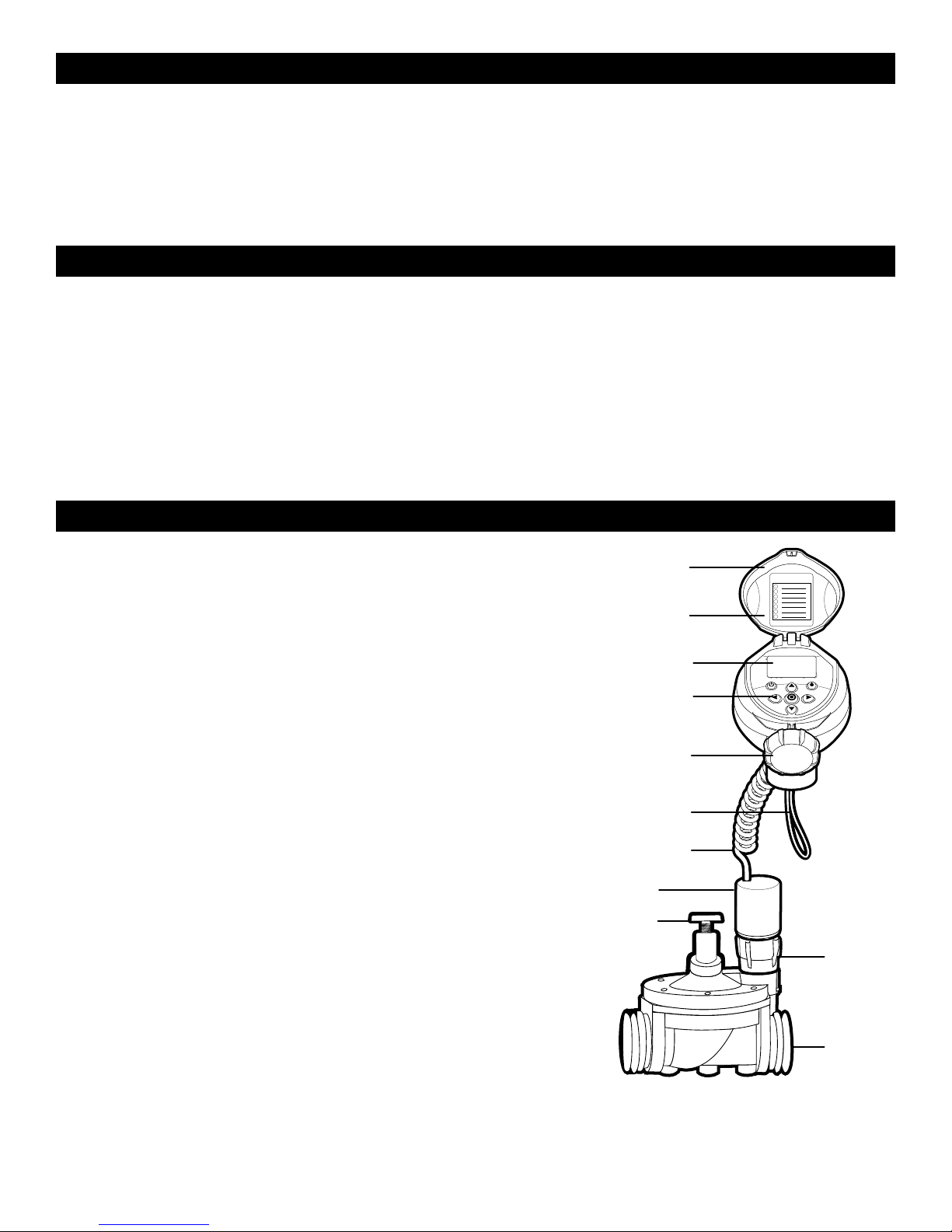
3. COMPONENT IDENTIFICATION
1. Timer cover
2. Quick reference label
3. LCD Display displays the icon-based
applications/ programs
4. 7 button programming keypad: Use for
programming, system on/off, manual run
and reviewing program
5. Battery compartment cap for
two AA alkaline batteries (not included)
6. Rain sensor yellow wire connection
7. Collapsible 36 in. solenoid wire
8. DC solenoid
9. Manual flow control
q
w
e
r
t
y
u
i
o
a
10. Solenoid Adapter
11. 3/4 in. professional grade in-line valve
s
1
Page 4
4. LCD DISPLAY AND CONTROLS
q
w
e
o
a
s
d
t
r
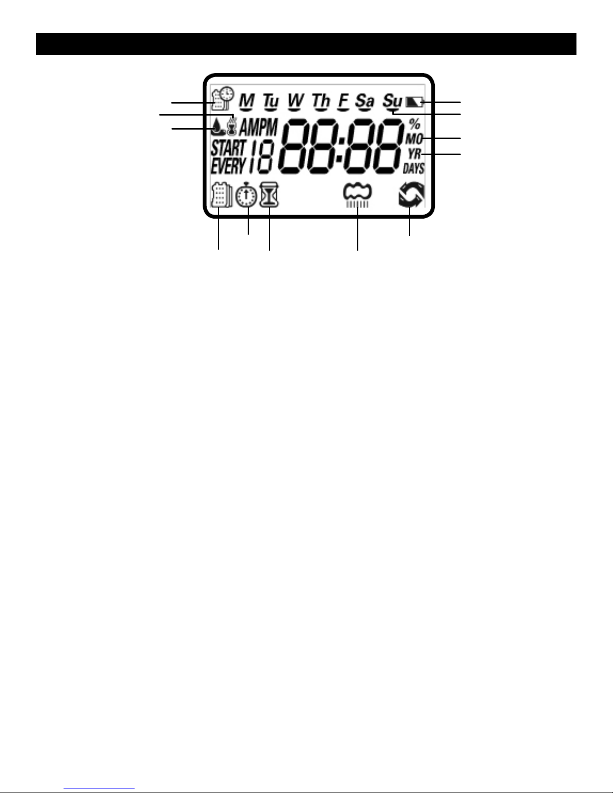
LCD Display
1. Time and Date Icon – Indicates current time and day is displayed
2. Sensor Icon – Appears when a rain sensor is active or when yellow wire loop
has been cut and watering is halted
y u
i
3. Watering Icon – Appears when valve is open
4. Set Watering Days Icon – Choose either specific days, odd/even days, every X
hours, or up to once every 30 days
5. Start Time Icon – Up to 4 start times per day available
6. Run Time Icon – Watering duration from 1 minute to 5 hours and 59 minutes
7. Rain Delay Icon – Delay irrigation setting from 1 to 99 days with automatic restart
8. Manual Run Icon – Appears when manual button is pushed
9. Battery Level Indicator – Flashes when batteries are low and need to be replaced
10. Day of the Week Underscore – Shows which day of the week the timer
will operate
11. Represents Month
12. Represents Year
2
2
Page 5
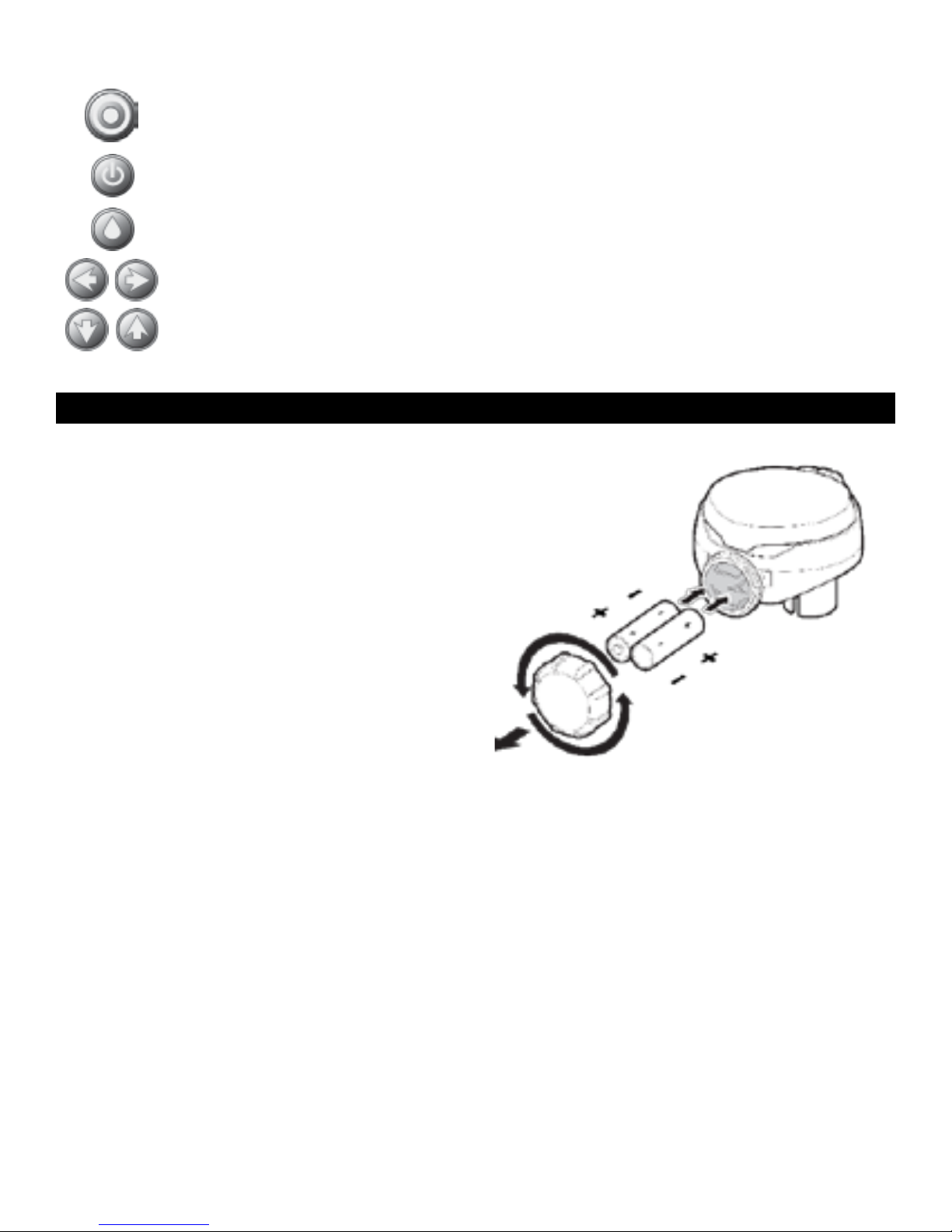
Control Buttons
Select programming mode
Turn program(s) ON/OFF
Start/stop a manual cycle
Move left/right to select a value
Raise/lower the selected value
5. INSTALLING THE BATTERIES
1. Open the battery compartment cap by
turning it counter-clockwise.
2. Install two, fresh, brand name, AA
alkaline batteries (not included)
and note the proper direction of the
positive and negative orientation on the
underside of the timer.
3. Insert and screw the battery cap
clockwise. Make sure to securely
tighten the cover firmly by hand only.
The timer display appears with a day,
PM, and the hour digit flashing. The timer
is ready to be installed and programmed.
3
Page 6
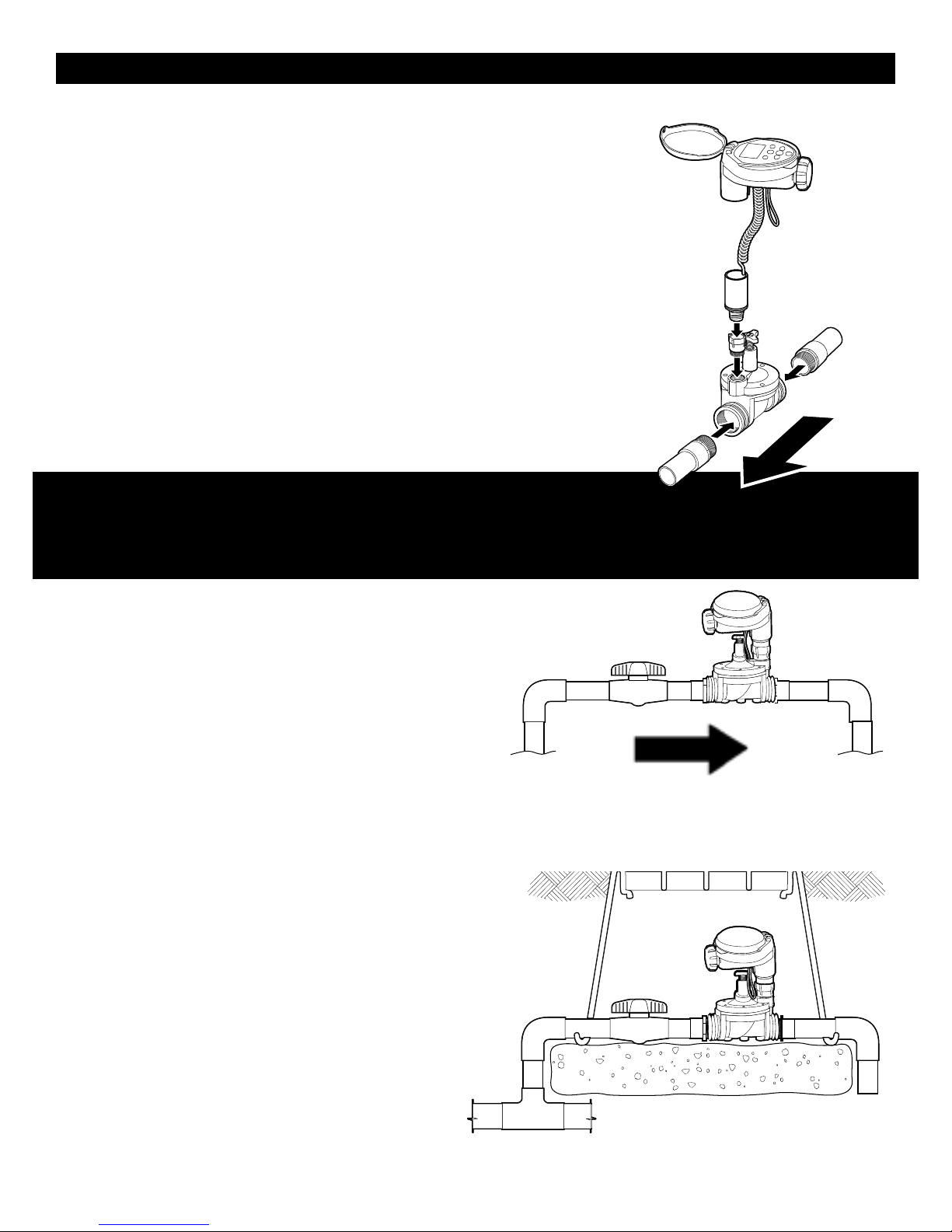
6. INSTALLATION
The RBC 7000 timer has a 3/4 in. inlet and outlet with
Figure 1
female pipe thread so it can be installed directly onto
3/4 in. PVC male pipe thread fittings as part of a sprinkler
valve manifold or as a stand-alone unit. (Figure 1)
OR
The RBC 7000 timer can be attached to a hose or faucet/
spigot using the two adapters that are included with the
timer. (Figure 7)
Warning: Wrap all pipe thread fittings with Teflon tape.
Do not use pipe dope/pipe cement on valve! This will
water
flow
damage the valve and void the warranty!
ATTENTION: PLEASE NOTE THE DIRECTION OF THE
VALVE WHEN INSTALLING. THE SOLENOID AND TIMER MOUNT IS POSITIONED
TOWARDS THE OUTLET SIDE OF THE VALVE.
Figure 2
IN-LINE INSTALLATION
Rated operating pressure: 10-125 PSI
Recommended Operating Pressure:
10-80 PSI
1. Shut off main water supply.
WATER FLOW
2. Install a 3/4 in. ball or gate valve onto the PVC pipe
or to the valve manifold before installing the timer (Figure 2 and 3). This valve can
be very useful as an emergency
backup to turn the system off. This
type of arrangement is used by
professional installers.
Figure 3
3. Turn water supply on to flush the line
and then shut the water off using the
ball or gate valve.
4. Install the timer wrapping Teflon
tape on all male pipe thread fittings.
Below ground installation
4
Page 7
5. Turn water supply on to pressurize the system. The timer will open momentarily
and then will shut off.
6. The unit is now ready to be programmed.
FAUCET INSTALLATION
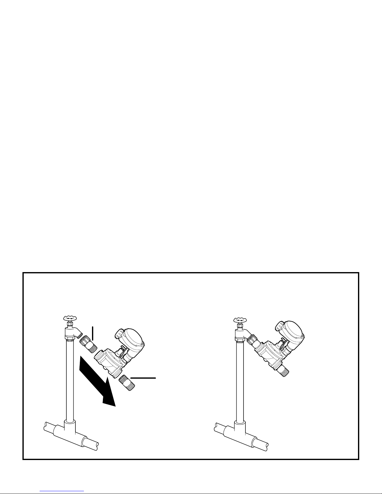
1. Wrap the swivel adapter and the nipple male pipe threads with 4-6 layers of
Teflon tape in a clockwise direction.
2. Screw the swivel adapter male threads into the inlet side of the controller valve
and tighten with a wrench or pliers. Repeat the steps with the ¾” MPT x MHT
nipple. (see Figure 4).
Note: Do not apply any Teflon tape to the male hose thread faucet.
3. Make sure the washer is in place inside the female swivel adapter, and then
screw the female swivel threaded clockwise onto the faucet and tighten by
hand only. Do not use pliers or a wrench. (Figure 5)
4. Turn on the faucet and check for leaks.
Warning: Do not tighten the swivel nut with pliers or wrench: Over-
tightening can cause damage to the swivel and washer resulting in leaks
and/or disconnection from the faucet.
Basic installation of converting the controller with pipe thread into a hose thread
3/4 in. FHT x MNPT
swivel adapter
water
flow
Nipple pipe
x hose thread
Figure 5Figure 4
5
Page 8
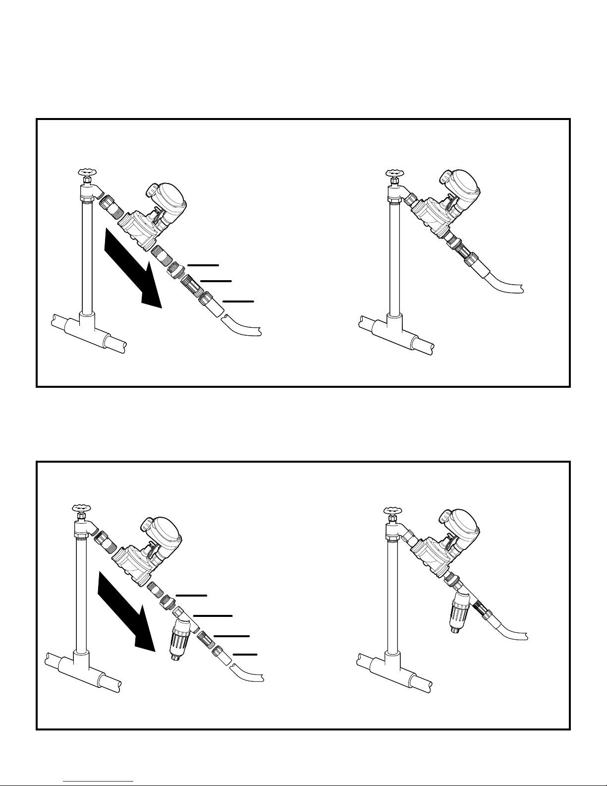
If a backflow preventer is part of the faucet (new houses) do not install any other
backflow preventer to the faucet. If backflow preventers are part of your city code
and you have purchased a unit as part of your drip system, install the device on the
downstream side of the RBC 7000 (Figure 6 and 6a).
Hose end drip system installation using a pressure regulator
Figure 6 Figure 6a
water
flow
backflow preventer
pressure regulator
swivel adapter
to drip system
It is best to include a filter on a drip system. The filter cleans small particles out of
the water that would otherwise clog the drippers. The filters can also automatically
apply fertilizer through a drip system (Figure 7 and 8).
Hose end drip system installation using a filter and a pressure regulator
Figure 8Figure 7
water
flow
backflow preventer
filter
pressure regulator
swivel adapter
to drip system
6
Page 9
7. PROGRAMMING
The RBC 7000 timer can be programmed to operate on any day of the week, odd
days or even days. In cyclical mode the RBC can also operate from every 1 hour up to
every 12 hours or from once a day up to every 30 days. The RBC has four start times
per day and durations from 1 minute up to 5 hours and 59 minutes.
This section explains the programming features, and the steps necessary to assign
irrigation schedules. To program the timer use the to select the desired
programming mode, the
to make the entry flash and the buttons to
change the value.
NOTE: Only a flashing value can be changed.
NOTE: If the last data entered stops flashing, press again to resume
programming and repeat the steps.
8. SETTING CURRENT TIME AND DATE
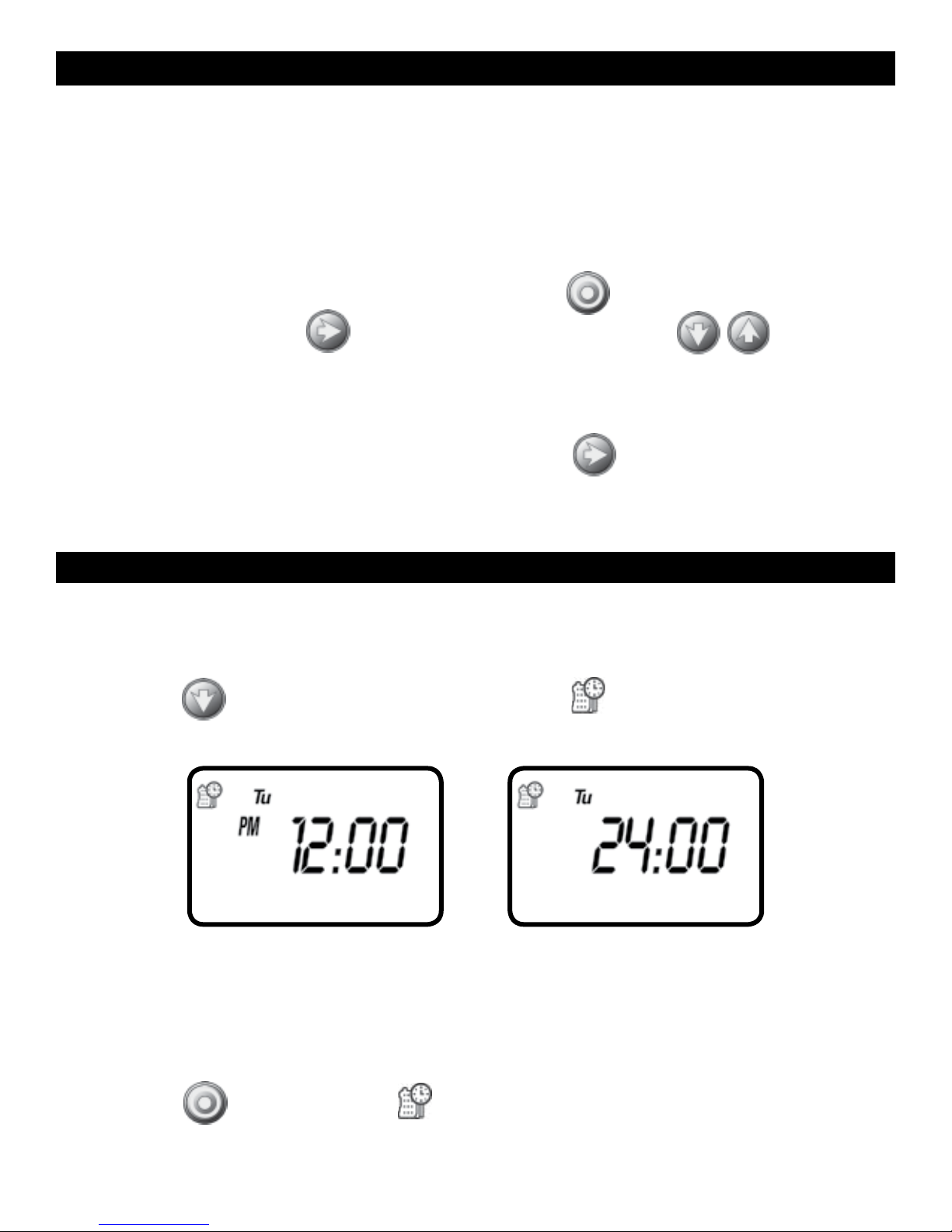
The timer can display the time in either a 12 or 24 hour format.
To change the time format, from the home screen:
1. Press the
button for three seconds until the display switches format
(AM/PM disappears).
SETTING THE CURRENT TIME AND DATE
To enable the timer to operate properly, the current time and date must
be set.
1. Press the
button, until the icon appears along with the time and the day
of the week.
7
Page 10
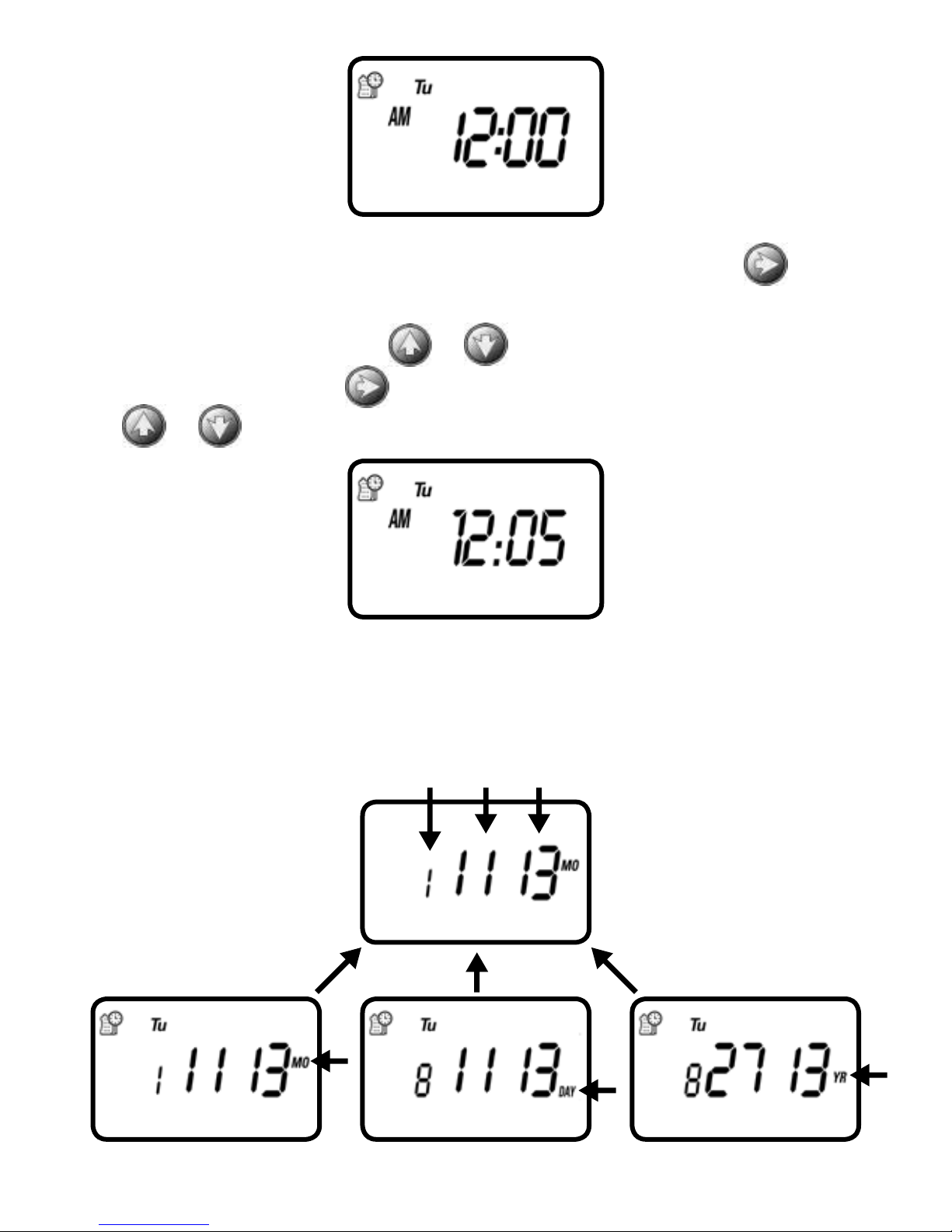
2. If the current time has not been set or needs to be updated press and the
hour digit starts flashing.
3. To set the current hour, press
4. To set the minutes, press
the
or to set the current time in minutes.
or (note AM and PM designations).
again and the minute digit starts flashing. Press
5. Repeat the steps to set the current date including, month, day and year. When
the date is selected and updated, the day of the week will be update at the
same time to correspond with the date.
MONTH DAY YEAR
8
Page 11
Press , to proceed to the next step, SET DAYS or to review the program.
Press
to move backward.
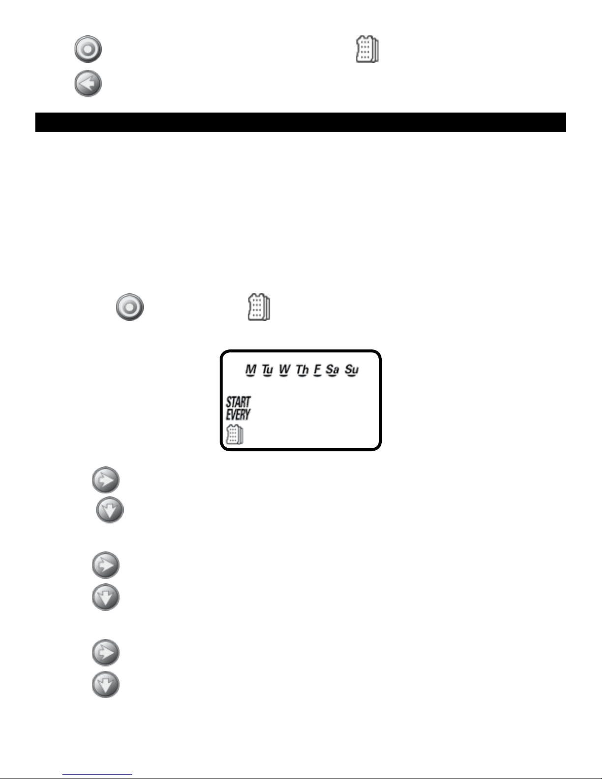
9. SETTING WATERING DAY SCHEDULES
Option 1 – Setting Specific Days of the Week:
This setting determines which days the RBC 7000 timer will operate. Choose either
watering on specific days of the week, EVEN/ODD days or cyclical from daily up to
once every 30 days. The timer’s default setting is to water on all specific days of
the week.
For example, if you want to water every Tuesday, Thursday and Sunday:
1. Press the
button until the icon and the days of the week appear on
the screen.
2. Press once and M (for Monday) starts flashing.
3. Press,
and underscore under M (Monday) disappears. Monday is
de-selected.
4. Press
5. Press
twice and W (for Wednesday) starts flashing.
and the underscore under W (Wednesday) disappears. Wednesday is
de-selected.
6. Press
7. Press
twice and F (Friday) starts flashing.
and the underscore under F (Friday) disappears. Friday is de-selected.
9
Page 12
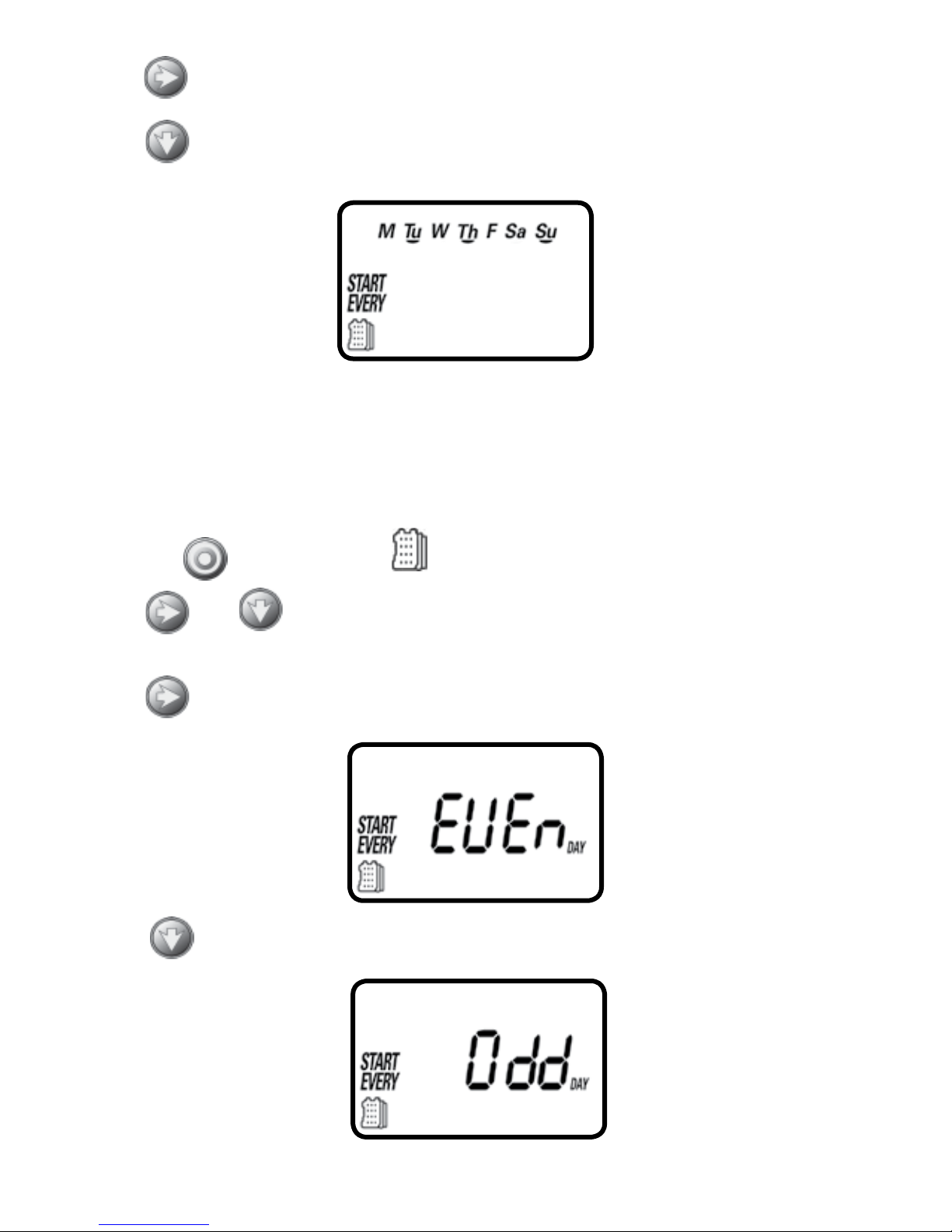
8. Press and the underscore under Sa (Saturday) starts flashing.
9. Press
and the underscore under Sa disappears. Saturday is de-selected.
Option 2 – Setting Even or Odd Days:
To select EVEN days, ODD days refer to the example.
Example: setting the timer to water on ODD days
1. Press the
button until the icon and the days of the week appear.
2. Press
and to skip all the days of the week (underscore must be
removed beneath all days).
3. Press
4. Press
and EVEN appears flashing.
and ODD appears flashing
10
Page 13
5. Press the button to proceed to the next step START TIME or to review
the program.
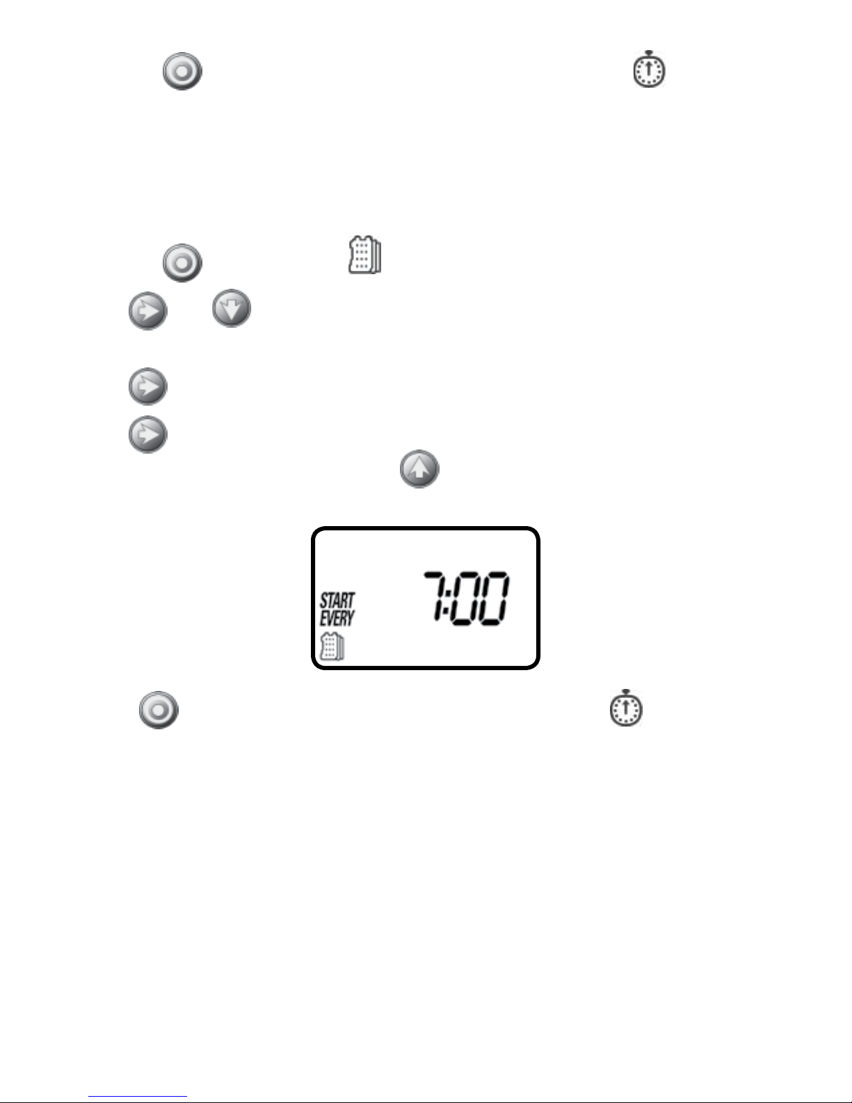
Option 3 – Setting every X hours:
Example: setting the timer to water every 7 hours
1. Press the
2. Press
button until the icon and the days of the week appear.
and to skip all the days of the week (underscore must be
removed beneath all days).
3. Press
4. Press
and EVEN appears flashing.
again and 1:00 hour appears flashing. To select the number of hours
between watering to 7 hours, press
until 7:00 appears on the display.
Press the button to proceed to the next step START TIME or to review
the program.
11
Page 14
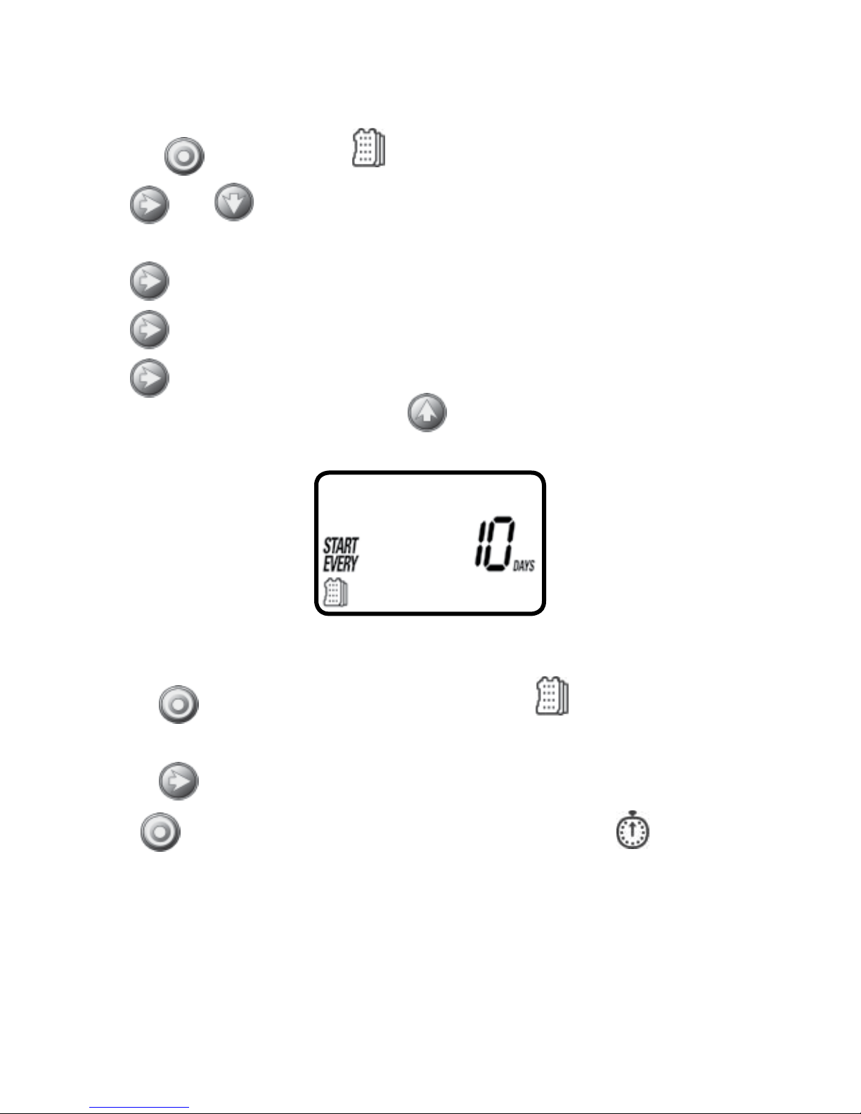
Option 4 – Setting every X days:
Example: setting the timer to water every 10 days:
1. Press the
2. Press
button until the icon and the days of the week appear.
and to skip all the days of the week (underscore must be
removed beneath all days).
3. Press
4. Press
5. Press
and EVEN appears flashing.
again and 1 hour appears flashing.
again and 1 DAY appears flashing. To select the number of days
between watering to 10 days, press
until 10 appears on the display.
To set the timer back to specific days mode:
1. Push the
button until – START EVERY and the icon appear at the bottom
left of the screen.
2. Push the
Press the
until the days of the week appear at the top of the screen.
button to proceed to the next step START TIME or to review
the program.
12
12
Page 15
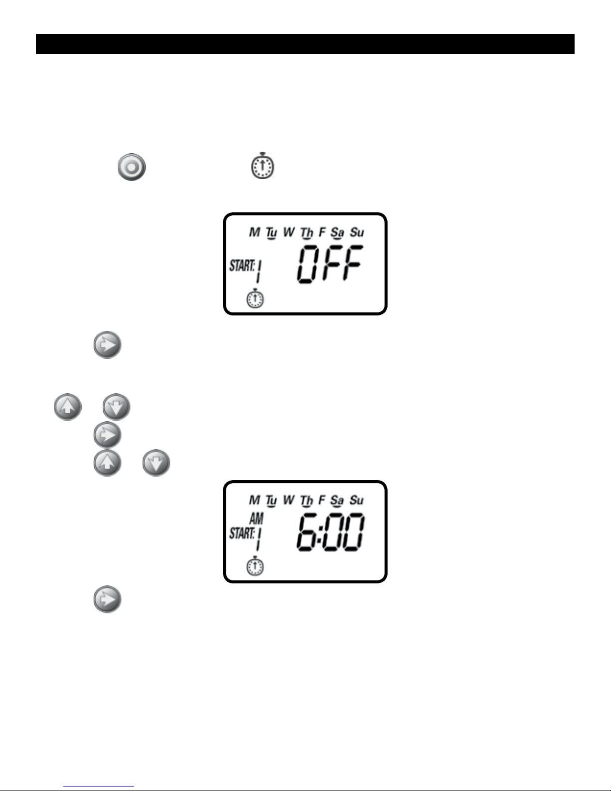
10. SETTING WATERING START TIMES
The RBC 7000 smart timer can have up to four separate irrigation start times
per day. (Note: if the timer is set to water every X hours, only one start time is
available to be programmed.)
To set a start time,
1. Press the
button until the icon appears. START 1, displays OFF or the
last start time programmed in START 1 appears.
2. Press and OFF (or the first start time programmed) begins flashing.
3. To set the desired first start time hour (note AM and PM designations), press
or .
4. Press
and the minutes start flashing.
5. Press
or and set the desired start time minutes.
6. Press again, the second start time and OFF or the last start time
programmed appear flashing. Repeat the steps to set the second, third, and
if needed,the fourth start time. During programming, if you are set to water
on specific days of the week, the screen also shows which days the timer will
operate with an underline.
13
Page 16
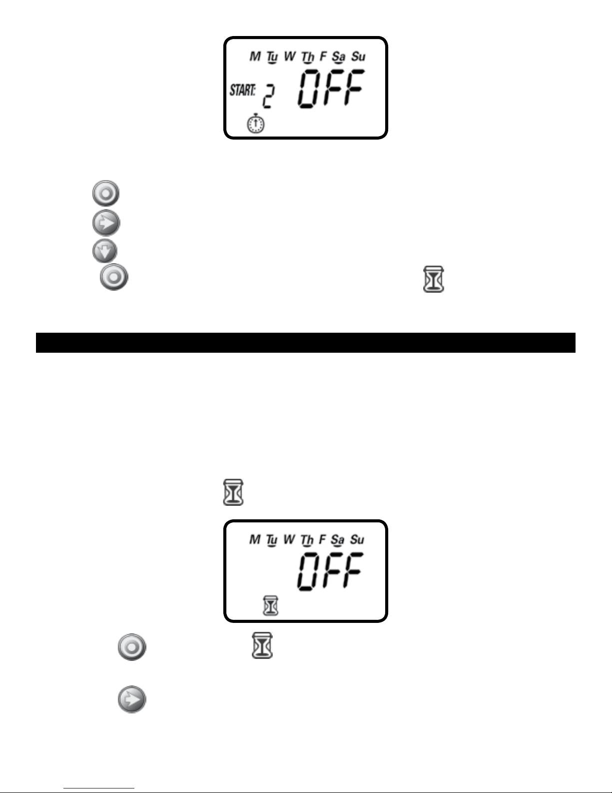
To delete a start time:
1. Press
2. Press
3. Press
Press the
until START 1 appears.
until the start time appears that you want to delete.
until the word OFF appears.
button to proceed to the next step RUN TIME or to review
the program.
11. SETTING WATERING RUN TIME DURATIONThis setting
determines the length of time the RBC 7000 smart timer will allow the valve
to remain open (duration is from 1 minute up to 5 hours and 59 minutes). For
example, setting watering run time to 10 minutes on certain days of the week will
program the timer to turn the water on for 10 minutes on each of the days chosen
and at every start time selected. (Note: if the timer is set to water every X hours,
the maximum duration is 59 minutes)
To set the watering run time
1. Press the button until the
setting appears. (OFF will appear if duration is set to 0)
2. Press the
button, and 0:05 (or the last run time programmed) appears.
:
icon appears and OFF or the last run time
14
14
Page 17
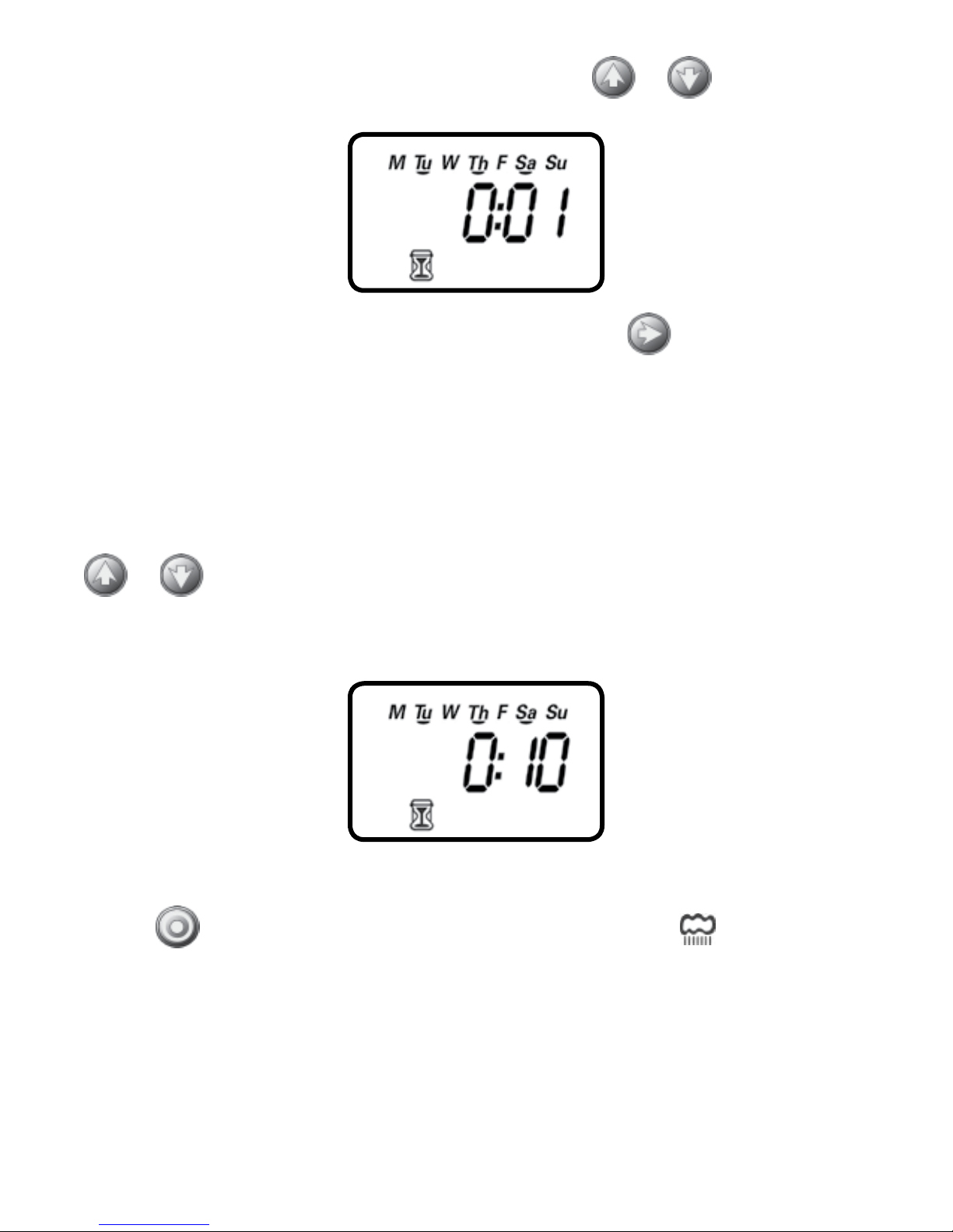
3. To set a desired watering run time in hours, press
or and select the
number of hours.
4. If only watering duration in minutes is required, press to skip the hour digit,
and the minutes will start flashing.
5. To set the desired watering duration in minutes (example of 10 minutes), press
or to select minutes. When programming the watering duration, if you
are set to water on specific days of the week, the screen will also show the days
the timer will operate with an underline.
At this point the controller’s normal programming is concluded.
Press the
button to proceed to the next step RAIN DELAY or to review
the program or to exit.
15
Page 18
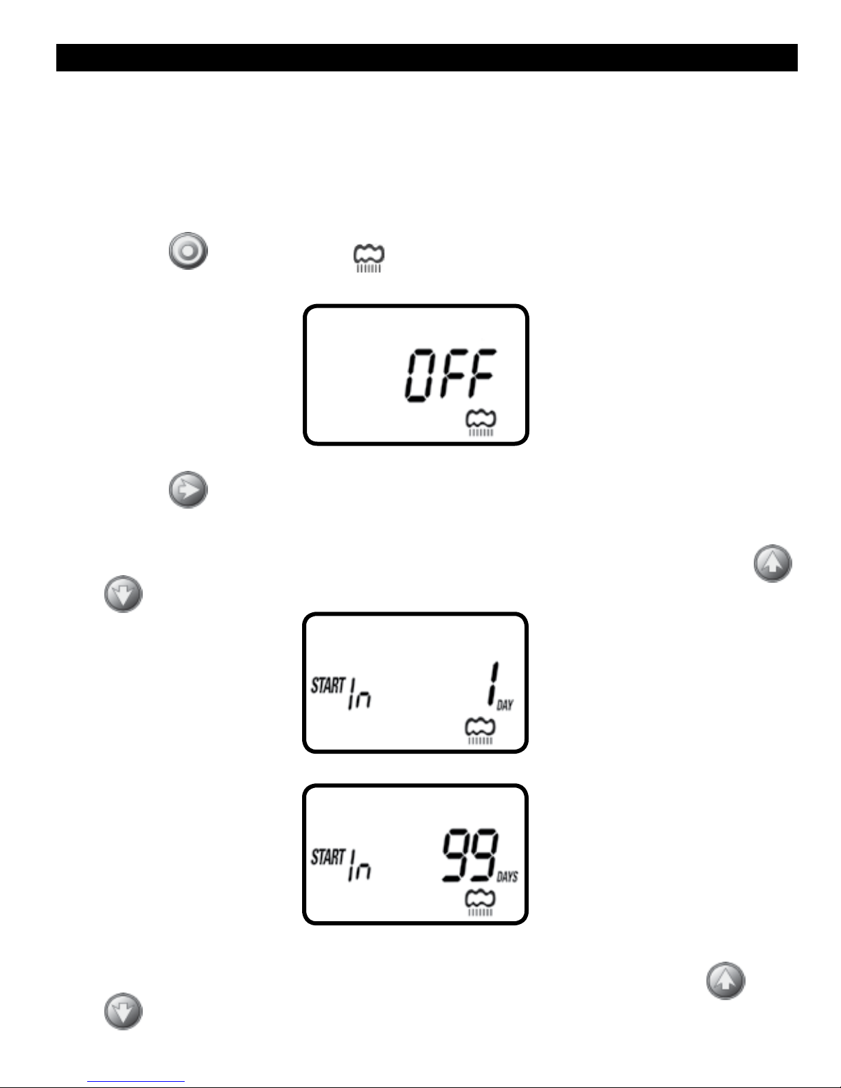
12. SETTING RAIN DELAY – OPTIONAL FEATURE
The Rain Delay setting is used to temporarily suspend all irrigation for a defined
number of days. For example, during rainy weather regularly scheduled programs
can be turned off from 1-99 days. At the end of the designated period, regularly
scheduled programming will resume automatically.
To set a temporary suspension of the program:
1. Press the
2. Press the
button until the icon and OFF appear.
button and OFF starts flashing.
3. To set the desired temporary suspension of the program (1-99 days), press
or
.
4. The temporary suspension of the program can be cancelled at any time by
re-entering Rain Delay screen and changing the setting to OFF. (Press
or
until OFF appears.)
16
Page 19
Note: OFF appears in between numeric value of 99 and 1.
Press the
button to review the program or to exit.
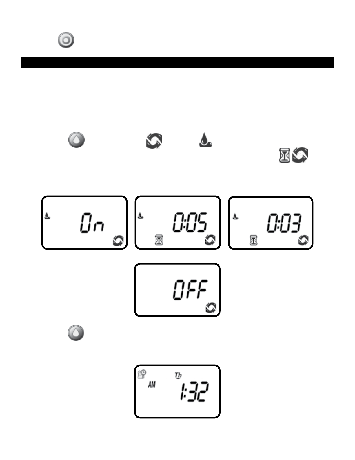
13. MANUAL WATERING
The manual mode allows the user to test the system and water for a specified run
time set in watering duration. The timer will automatically stop watering at the end of
the defined irrigation period. The originally programmed irrigation schedule continues
to function at the times assigned. The sensor condition is disregarded in this mode.
To start a manual run,
1. Press the
momentarily and then the last watering duration is displayed with
button, and the icon and icon appears. ON appears
.
The timer will open the valve and in 5 seconds a count down of the remaining
irrigation duration appears, showing when the timer will close the valve.
2. Press the button to end manual run.
3. After 5 seconds the display will revert to the current time screen.
17
Page 20
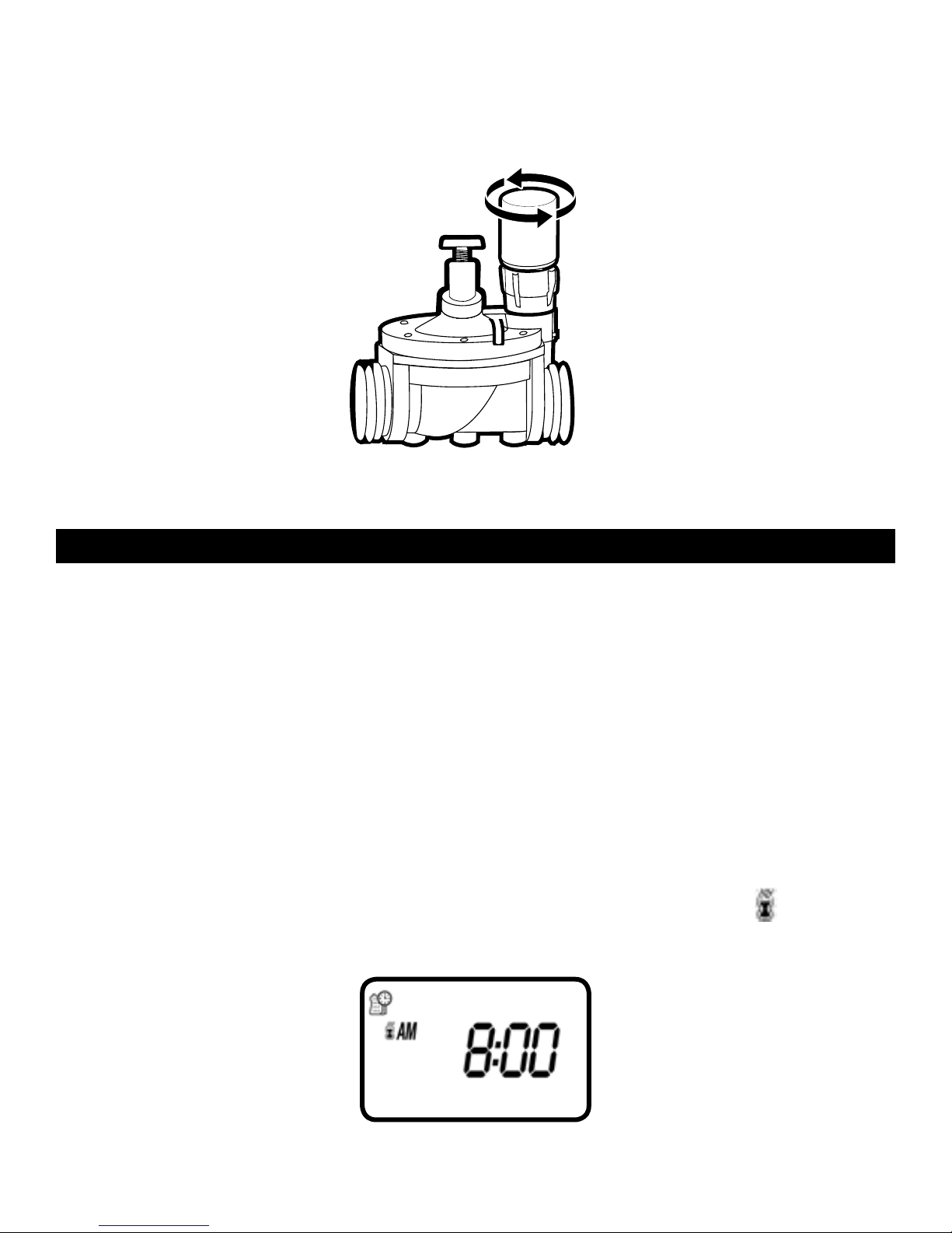
To activate a manual watering without the use of the timer – turn the solenoid a
1/4 turn counterclockwise. To stop, tighten the solenoid clockwise by hand only –
do not over tighten (figure 9).
FIGURE 9
14. CONNECTING A RAIN SENSOR
Most “normally closed” rain sensors can be connected to the RBC 7000 timer.
The function of the sensor is to prevent automatic watering by
the set program due to excessive rainfall.
To connect the sensor to the timer, please follow these steps:
1. Cut the yellow wire loop that exits the timer in the middle of the loop.
2. Strip approximately 1/2 in. of insulation from the end of each wire.
3. Splice one yellow wire to each of the wires coming from the sensor.
Use waterproof wire connectors to secure the connections.
4. When the sensor is active and preventing automatic operation, the
icon will
appear on the display.
18
Page 21
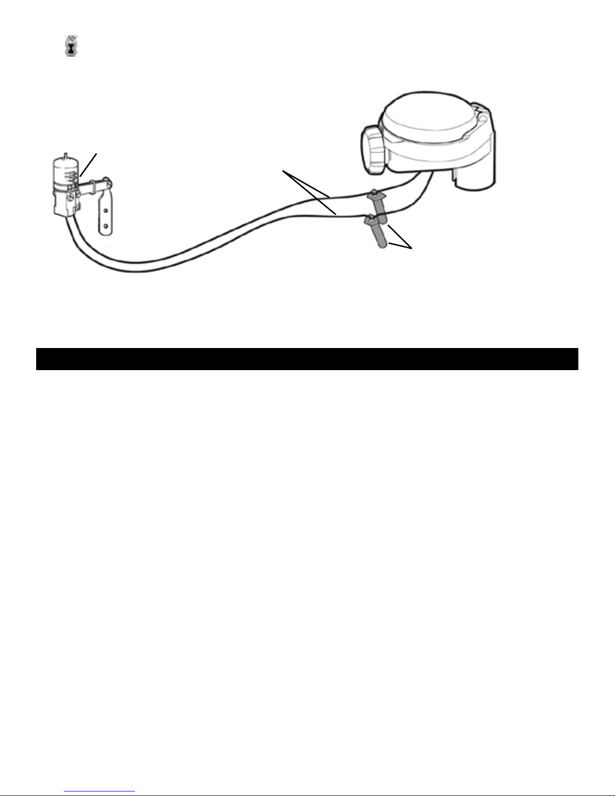
The icon will only appear when sensor is active or if the wire has been cut.
FIGURE B
SENSOR
YELLOW SENSOR
WIRES
WATERPROOF
WIRE CONNECTORS
Recommended rain sensors are the Rain Bird RSD and Hunter Mini-Clik
15. CHANGING THE BATTERIES
The RBC 7000 timer’s batteries can last up to 3 years when using name-brand
AA alkaline batteries. Actual battery life will depend on the sensitivity of the
installed batteries to temperature ranges experienced by the timer as well as the
number of valve operations programmed per day. To ensure proper operation, it
is recommended that the RBC 7000 timer be checked regularly and the batteries
replaced once the low battery indication starts flashing.
The RBC 7000 timer is designed to maintain the current time settings for up to 60
seconds with the batteries removed.
To change the batteries, see section 5.
Note: If the batteries are dead or drained, manual operation can also be
accomplished by turning the solenoid counterclockwise, or by turning the external
bleed screw counterclockwise. This will cause the valve to open. Both must be
turned clockwise to close the valve.:
19
Page 22

16. MAINTENANCE, TROUBLESHOOTING AND REPAIRS
To restore the timer to the default settings
1. Press the
button until the START EVERY is displayed and the icon
appears on the bottom left of the screen.
2. Press and hold down the
for three seconds.
3. The screen returns to the home screen (clock) and all the default settings are
restored. The current time and date is retained.
PROBLEM: Timer fails to open automatically or manually
CAUSE: No water pressure
SOLUTION: Open main water supply valve
CAUSE: Flow control knob is turned down
SOLUTION: Turn flow control knob clockwise to open
PROBLEM: Valve/actuator functions via the manual mode but
not automatically
CAUSE: Timer is set to OFF mode
SOLUTION: Verify that the timer does not show OFF in current time mode
CAUSE: AM/PM not set correctly in current time mode
SOLUTION: Check current time, change AM/PM if necessary
CAUSE: AM/PM not set correctly in start time mode
SOLUTION: Check start time(s), change AM/PM if necessary
CAUSE: Rain delay is preventing watering
SOLUTION: Set rain delay to off
CAUSE: Yellow sensor wires have been cut
SOLUTION: Re-connect sensor wires together with waterproof connector
CAUSE: Sensor is installed and is in a state that prevents watering
SOLUTION: Check sensor and wire splices and verify sensor is normally closed
20
Page 23

PROBLEM: The display is blank
CAUSE: No buttons have been pushed in the previous 15 minutes
SOLUTION: Push any button
PROBLEM: Valve fails to close
CAUSE: Solenoid is loose
SOLUTION: Tighten solenoid by turning it clockwise to the right
CAUSE: Valve is installed backwards
SOLUTION: Check flow arrow and verify arrows points away from
water source – reverse valve if necessary
CAUSE: Debris is blocking solenoid port
SOLUTION: Shut off water supply, unscrew and remove solenoid, then open
water supply and flush out solenoid port, re-install solenoid
CAUSE: Flow control knob is too far open
SOLUTION: Turn flow control knob clockwise and retest
CAUSE: Drip System flow rate is below minimum flow rate
SOLUTION: Increase system flow rate by adding or changing drippers
PROBLEM: Rain sensor does not prevent watering
CAUSE: Rain sensor is normally open, malfunctioning, or not wired correctly
SOLUTION: Verify that sensor icon appears on display when pin is pushed
down and check all wire splices
PROBLEM: Timer waters more than once per day
CAUSE: More than one start time has been programmed
SOLUTION: Change start time 2, 3, and 4 to OFF
21
Page 24

17. WARRANTY
DIG CORPORATION warrants these products to be free from defects in material and workmanship
for a period of three years from date of purchase. This warranty does not cover damage resulting
from accident, misuse, neglect, modification, improper installation or subjection to line pressure
in excess of 125 lbs. per square inch for anti-siphon valves, in-line valves and for actuators. This
warranty shall extend only to the original purchaser of the product for use by the purchaser.
The obligation of DIG CORPORATION under this warranty is limited to repairing or replacing
at its factory this product which shall be returned to the factory within three years after the
original purchase and which on examination is found to contain defects in material and
workmanship. DIG CORPORATION SHALL IN NO EVENT BE LIABLE FOR ANY INCIDENTAL OR
CONSEQUENTIAL DAMAGES OF ANY KIND; THE SOLE OBLIGATION OF DIG BEING LIMITED TO
REPAIR OR REPLACEMENT OF DEFECTIVE PRODUCTS. SOME STATES DO NOT ALLOW THE
EXCLUSION OR LIMITATION OF INCIDENTAL OR CONSEQUENTIAL DAMAGES, SO THE ABOVE
LIMITATION OR EXCLUSION MAY NOT APPLY TO YOU.
Unattended use for prolonged periods without inspection to verify proper operation is beyond
the intended use of this product, and any damage resulting from such use shall not be the
responsibility of DIG CORPORATION. There are no warranties, which extend beyond the
description on the face hereof. In the case of purchase of the product for use other than, for
irrigation purposes, DIG CORPORATION hereby disclaims any implied warranties including any
warranties of merchantability and fitness for a particular purpose. In the case of the purchase of
the product for personal, family or household purposes, DIG CORPORATION disclaims any such
warranties to the extent permitted by law. To the extent that any such disclaimer or implied
warranties shall be ineffectual, then any implied warranties shall be limited in duration to a
period of three years from the date of the original purchase for use by the purchaser. Some
states do not allow limitation on how long an implied warranty lasts, so the above limitation may
not apply to you.
In order to obtain performance under this warranty, the unit must be returned to the factory,
along with proof of purchase indicating original date of purchase, shipping prepaid, addressed
as follows:
DIG CORPORATION, 1210 Activity Drive, Vista, CA 92081. Repaired or replaced units will be
shipped prepaid to the name and address supplied with the unit returned under warranty. Allow
four weeks for repairs and shipping time. Repair of damaged units not otherwise within warranty
may be refused or done at a reasonable cost or charge at the option of DIG CORPORATION.
This warranty gives you specific legal rights, and you may also have other rights, which vary
from state to state.
22
Page 25
18. TECHNICAL ASSISTANCE
Should you encounter any problem(s) with this product or if you do not understand its
many features, please refer to this operating manual first. If further assistance is required
DIG offers the following customer support:
DIGPRO
™
Technical Service USA
DIG’s Technical Service Team is available to answer questions in English and Spanish from
8:00 AM to 5:00 PM (PST) Monday-Friday (except holidays) at 800-344-2281.
Questions can be e-mailed to [email protected] or faxed to 760-727-0282.
Specification documents and manuals are available for download at www.digcorp.com.
Customer Assistance Outside the USA
Contact your local distributor.
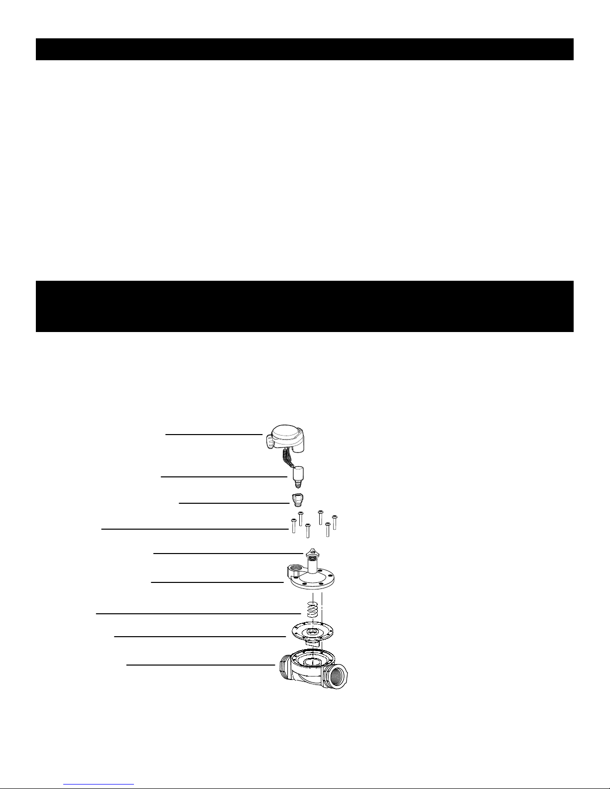
19. TO ORDER REPLACEMENT OR SPARE PARTS:
PLEASE ORDER ONLINE AT WWW.DIGCORP.COM
We at DIG Corporation understand that most dealers do not carry spare parts. For your
convenience, if you need one of these parts, please order online at www.digcorp.com.
Timer with Solenoid
2-wire DC solenoid
Solenoid valve adapter
Screws
Flow control knob
Bonnet assembly
Spring
Diaphram
In-line valve
23
Page 26

Website: E
www.digcorp.com
e-mail: [email protected]
1210 Activity Drive
Vista, CA 92081-8510, USA
26-221 REV C 082415
Printed in the USA
DIG is a Registered Service Mark of DIG Corp.
 Loading...