

Page 1
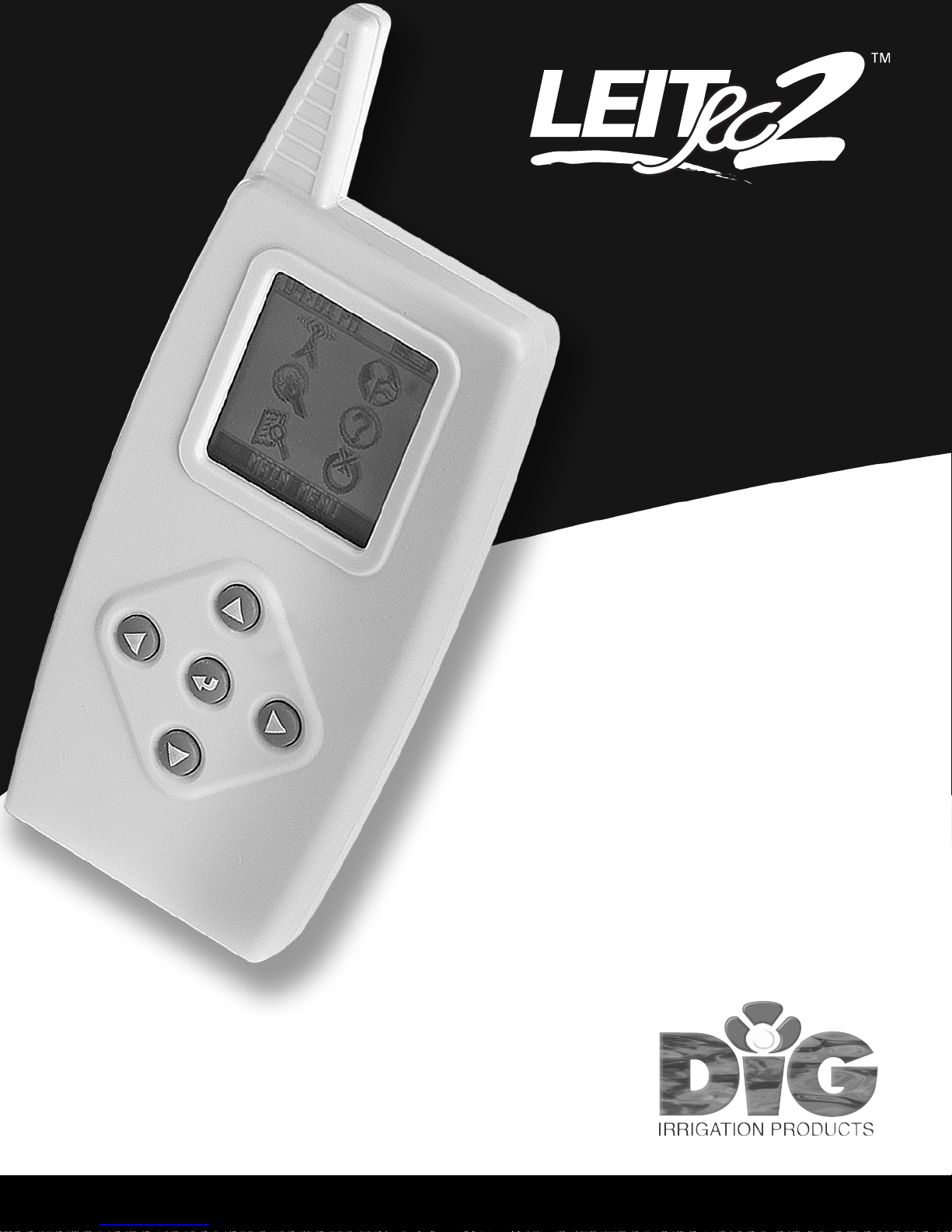
2-Way Radio Remote Handset
Operating Instructions
English
1
Page 2

Table of Contents
A. Introduction …………………………………………………………………3
B. About the LEIT RC2 handset ……………………………………………………3
C. Technical assistance …………………………………………………………4
D. Copyright and compliance ……………………………………………………5
E. Features ………………………………………………………………………6
1. System ……………………………………………………………………7
2. Main menu …………………………………………………………………8
2.1 Navigation menu ………………………………………………………8
2.2 Radio uplink ……………………………………………………………8
2.3 Language selection ……………………………………………………9
2.4 Handset setup …………………………………………………………9
2.5 Help …………………………………………………………………12
2.6 Connecting to a LEIT-2 via FIND…………………………………………12
2.7 Turn off the handset ……………………………………………………13
3. Initial communication ………………………………………………………13
4. Controller menu ……………………………………………………………15
4.1 Manual run ……………………………………………………………15
4.2 Setting or changing a program …………………………………………17
4.3 Setting a monthly budget ………………………………………………19
4.4 Controller setup ………………………………………………………20
4.5 Reports menu …………………………………………………………24
4.6 Exit controller menu ……………………………………………………26
5. Troubleshooting …………………………………………………………26
5.1 General information for handset and controller …………………………26
5.2 Programming problems…………………………………………………27
5.3 The password has been changed or forgotten……………………………27
6. Warranty …………………………………………………………………28
2
Page 3

A. Introduction
Thank you for purchasing DIG's LEIT RC2 remote control handset, which
operates as a part of the LEIT-2 system. This manual describes how to get the
LEIT RC2 handset up and running quickly. After reading this manual and having
been familiarized with the basic functionality of the handset, the manual can
be used as a reference for less common tasks in the future.
B. About the LEIT RC2 Handset
The LEIT-2 is a wireless irrigation control system that combines the RC2
remote control handset with a 2-station ambient (solar) powered controller.
The LEIT RC2 remote control handset is an advanced wireless device that is
used to communicate with up to 99 LEIT-2 controllers, or 198 valves, from a
distance of up to 350 feet (100 m) line of sight. The LEIT RC2 handset has a
large LCD display and sophisticated, intuitive icon-based software
used to
review and program the LEIT-2 controllers. All LEIT-2 controller functions are
controlled and reviewed by the RC2 remote handset. After installation, no
further visits to the controller are required.
IMPORTANT:
controllers are automatically limited to daylight hours when there is sufficient
light energy. Longer bright light days will enable the radio to operate
automatically over longer parts of the day, including through the night.
Communication between the LEIT RC2 handset and the LEIT-2
3
Page 4

C. Technical Assistance
Should you encounter any problem(s) with this product or if you do not
understand its many features, please refer to this operating manual first. If
further assistance is required DIG offers the following customer support:
Technical Service USA
DIG's Technical Service Team is available to answer questions from 8:00
AM to 5:00 PM (PST) Monday-Friday (except holidays) at 800-322-9146.
Questions can be e-mailed to [email protected] or faxed to
760-727-0282.
Specification documents and manuals are available for download at
www.digcorp.com/leit.
Customer Assistance outside the USA
Contact your local distributor.
4
Page 5
D. Copyright and Compliance
Copyright 2010 DIG Corporation. All rights reserved. LEIT RC2 and LEIT-2
are each trademarks of DIG Corporation. Patent Pending
FCC, CE, IC, Canada and Australia compliance
To comply with FCC RF exposure compliance requirements, the antenna used for this
transmitter is installed to provide a separation distance of at least 8 inches (20 cm) from all
persons (not including hands, wrist, feet and ankles) and must not be co-located or operating
in conjunction with any other antenna or transmitter.
This device is required to comply with FCC RF exposure requirements for mobile and fixed
transmitting devices. This model transceiver generates and uses radio frequency energy. If not
installed and used in accordance with the manufacturer's instructions, it may cause
interference to radio and television reception.
CONTROLLER FCC ID: UJV-LEIT01 IC: 6694A-LEIT01
HANDSET FCC ID: UJV-LEIT02 IC: 6694A-LEIT02
This equipment has been tested and found to comply with the limits for a Class B digital
device, pursuant to part 15 of the FCC Rules. These limits are designed to provide reasonable
protection against harmful interference in a residential installation. This equipment generates
uses and can radiate radio frequency
energy. If not installed and used in accordance with the
instructions, the remote may cause harmful interference to radio communications. However,
there is no guarantee that interference will not occur in a particular installation. If this
equipment does cause harmful interference to radio or television reception, which can be
determined by turning the equipment off and on, the user is encouraged to try to correct the
interference by one or more of the following measures:
• Reorient or relocate the receiving antenna.
• Increase the separation between
the equipment and receiver.
• Connect the equipment into an o
utlet on a circuit different from that to which the receiver is
connected.
• Consult DIG technician for help.
Warning: the user should make no field changes or modifications to the LEIT-2 controller or
the LEIT RC2 handset. All adjustments and changes must be made at DIG's facility under the
specific guidelines suggested in our instruction manual. Any tampering or modification to the
equipment will void the users authority to operate the unit, render the equipment in violation
of FCC part 15 and will void the warranty.
5
RC2inst:Layout 1 4/28/08 7:51 AM Page 5
Page 6

E. Features
• Global Stop command will turn off all valves within radio range
• 2 programs with 4 start times per program
• Run times from 1 minute and up to 5:59 hours in 1 minute increments
• 365 day calendar with leap year
• Custom programming with 7 day calendar or intervals of 1-30 days in
odd/even or every day rotation
• Individual monthly water budgeting from 10-200% in 10% increments
• Programmable rain delay up to 99 days with auto restart
• Status report provides various function information on the controller
• Monthly Off feature allows any month of the year to be inactive
• Permanent Events Off feature allows any 3 days of the year to be inactive
• LEIT RC2 handset can perform many functions, such as review status, check
history reports, adjust budgeting, program rain delays and perform a
manual
run and tests
• Upload and change programs for up to 99 controllers
• Multilingual software in English, Spanish, Italian, French, German and
Portuguese
• The handset has a 2-way radio with operating range of up to 350' (100 m)
line of sight
• Can connect to rain sensor or any sensor to override a program
• Radio frequency is in the ISM band 902-928 MHz (869.7-870 MHz CE) FCC,
Canada, Australia and CE certified
• Client ID enables the user to have a unique identity code for their handset
and controllers; this is a security feature that locks out unauthorized users
• Environmentally friendly: Certified lead free, uses light as a source of energy
6
Page 7
1. System
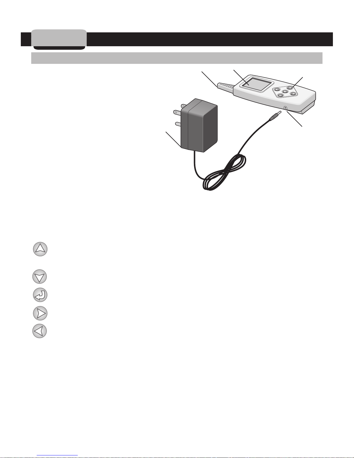
1.1 Parts Identification
1. LCD Display
2. Programming Buttons
3. Antenna
4. Battery Socket Outlet
5. Battery Charger
1. LCD Display
Displays the icon based applications stored in the handset.
2. Programming Buttons
Use these 5 buttons to program, modify, review and communicate with the
LEIT-2 controller.
f
d
b
c
e
Use to raise (increase) the value of the selected parameter or to unlock
the ID
Use to lower (decrease) the value of the selected parameter.
Use to accept and/or, select the desired programming mode.
Use to move the cursor to the right.
Use to move the cursor to the left.
3. Antenna
See FCC compliance.
4. Battery Socket Outlet
Plug the battery charger into the battery socket.
5. Battery Charger
Plug the battery charger into the wall to power the R
C2.
7
Page 8
1.2 Battery charge outlets and recharging the battery
The LEIT RC2 contains a cell battery pack that is rechargeable using the
AC/DC wall mounting charger 120 or 220 VAC/60 h2, 12 VDC @150 mA. To
charge the LEIT RC2 handset, plug the wall mount charger into the wall and
connect the power connector into the side of the LEIT RC2 handset. The initial
charge takes approximately 8 hours. Do not disconnect the handset during the
initial charge. When in use, the handset should be charged daily for a few
hours as needed. If the handset is charged, you will see a charging icon and a
battery appear. The battery repeats a filling action, indicating that the battery
is charging. Once the battery is charged, it will stop the filling motion, and the
wording CHARGED will appear. A car charger model 30-851 is available, if
needed.
The LEIT RC2 handset is
ready for setup and communication.
2. Main Menu
The SETUP MENU screen allows the user to set the LEIT RC2 handset in just a
few steps. In going though these steps select the time format (AM/PM or 24
hour), then in SET TIME/DATE screen set the time and date. In HANDSET
SETUP assign Handset ID and Client ID for identification purposes when
linking to a LEIT-2 controller. After setup is complete, the handset it is ready
for communication.
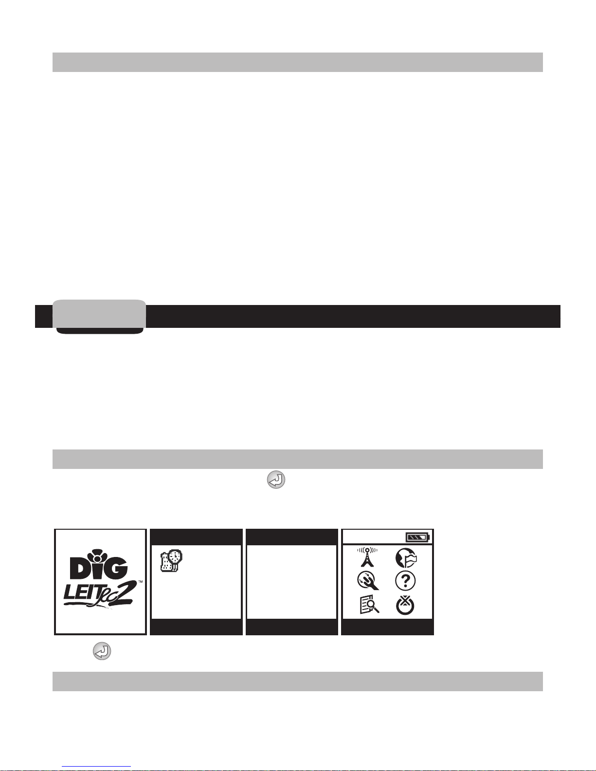
2.1 Navigation Menu
After charging the handset, press to navigate through the initial screens.
The DIG logo screen, a time/date screen, software version screen and then,
the MAIN MENU screen will appear.
10:00
SW V: 1.00.00
10:00:00 AM
MONDAY
7/10/2006
EE V: 1.00.00
TIME / DATE VERSION MAIN MENU
Press to enter the MAIN MENU screen.
2.2 Radio Uplink
The RADIO UPLINK screen allows the LEIT RC2 handset to link to a LEIT-2
8
Page 9
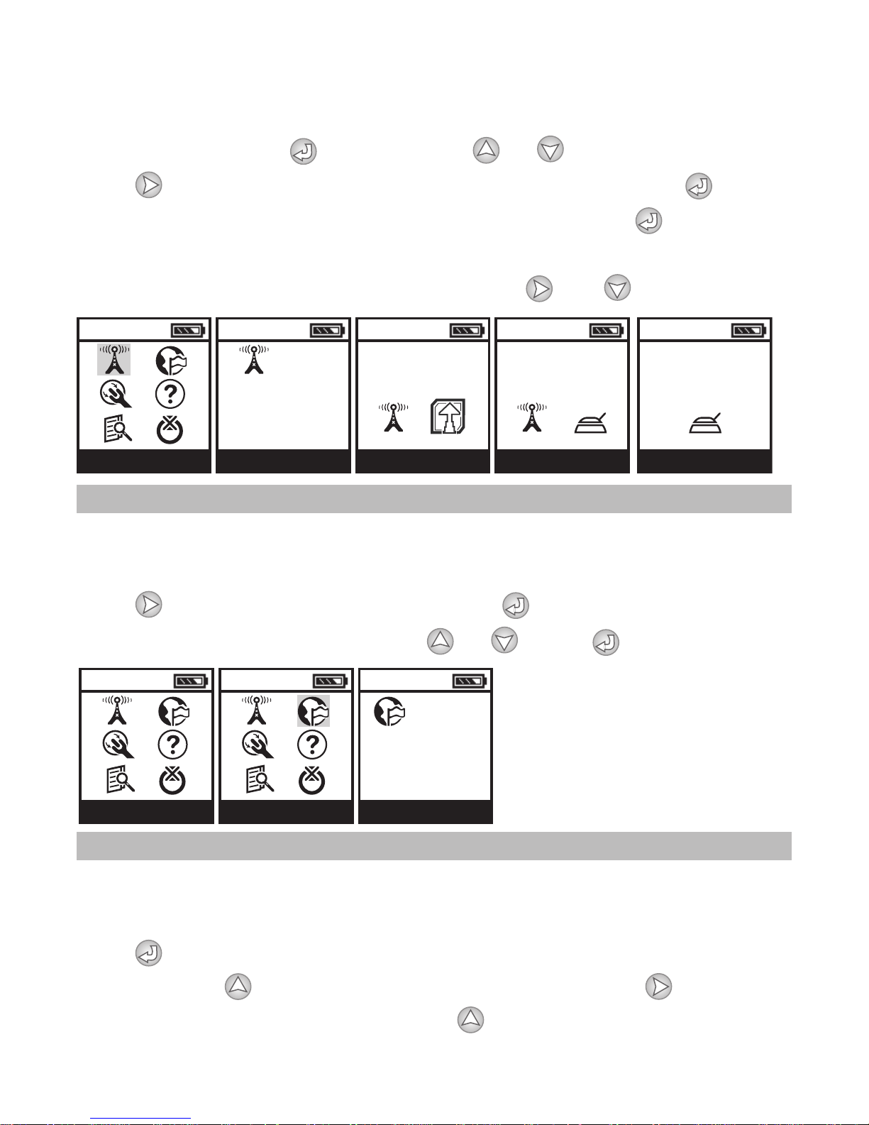
controller in a few steps. While going though these steps the user will enter
the Controller ID, which is used for identification purposes when linking to a
LEIT-2 controller. Press to select. Press or to select the first digit.
Press and repeat for the second digit. After selecting ID press to
connect. After connecting to the controller, continue to press , the
controller description, ID and activity can be reviewed until the CONTROLLER
MENU appears. To select another function press and .
10:00 10:00 10:00 10:00 10:00
ARE YOU SURE? CONNECTING CONNECTED
CONTROL ID: XX
NO DESCRIPTION
RADIO UPLINK RADIO UPLINK YES / NO CONNECT CONNECT
2.3 Language Selection
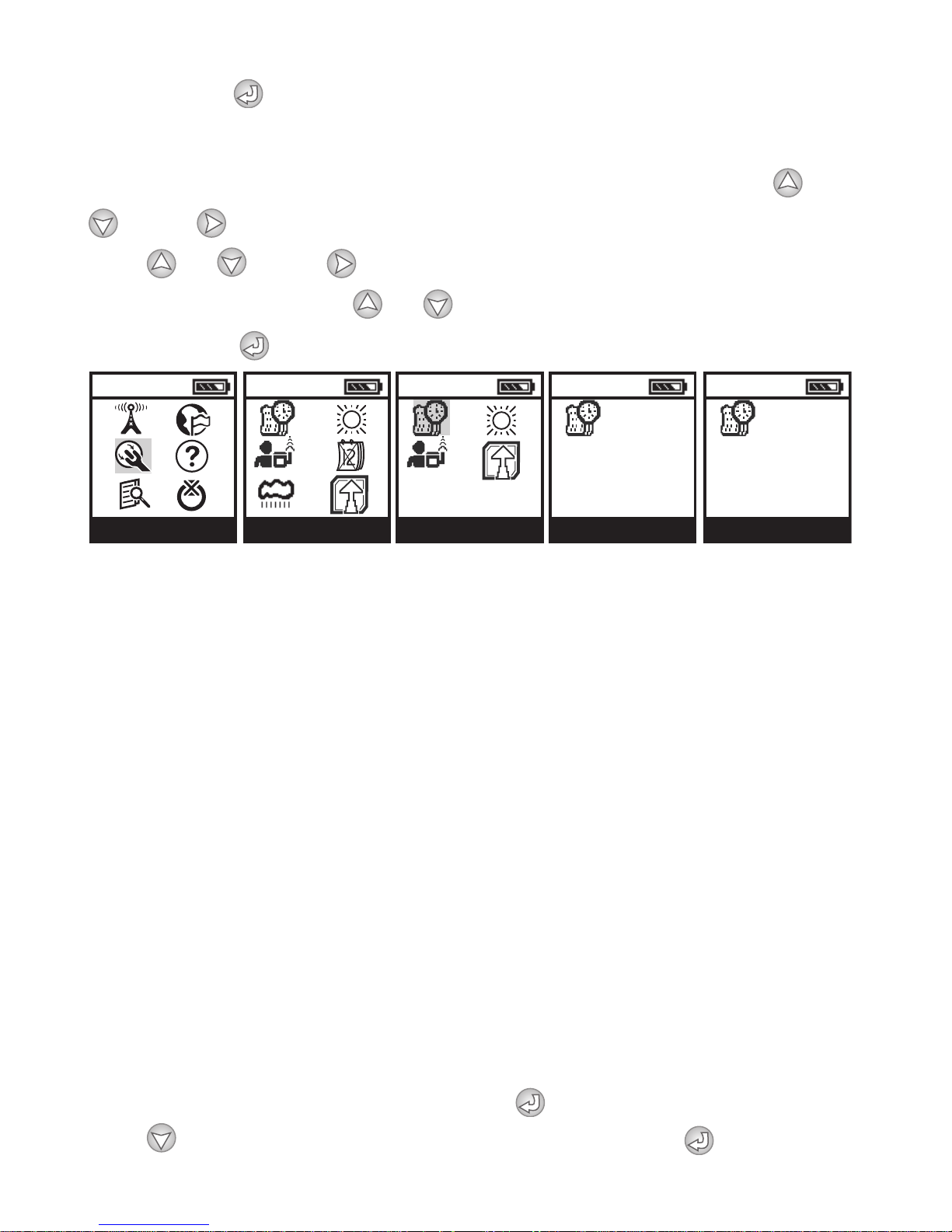
1 of 6 languages can be selected: ENGLISH, FRENCH, ITALIAN, GERMAN,
PORTUGUESE or SPANISH. English is the default language.
Press and select the language icon. Press to enter the language
screen. To change the language press or . Press to continue.
10:00 10:00 10:00
ENGLISH
MAIN MENU LANGUAGE LANGUAGE
2.4 Handset Setup
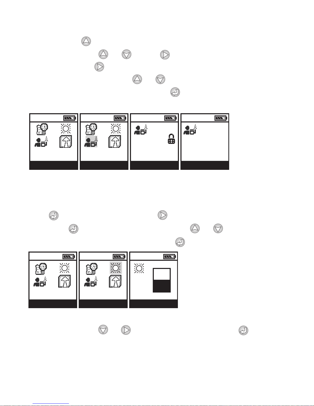
1. Set Time and Date
a. Select the Time and Date Format
Press to set the time and date format. The words 12-HOUR AM/PM is
flashing. Press to change the format (if needed), or press to skip time
format and select the date format. Press to change the date format if
9
Page 10
needed. Press to continue and to set the time and date.
10:00 10:00 10:00 10:00 10:00
SETUP MENUSETUP SET TIME / DATE SET TIME / DATE
12-HOUR
MM/DD/YYYY
SET TIME / DATE
10:00:00 AM
MONDAY
7/10/2006
b. Setting Current Time and Date
The hour digit appears (digits flashing). To set the current hour press or
. Press and the minute digit appears flashing. To set the minute digit,
press or . Press and the day of the week appears flashing. To set
the day of the week press or . Repeat the steps to set the month and
the year. Press to continue.
2. About the Handset and Controller Communication Method
In order to establish 2-way communication between the LEIT RC2 handset and
the LEIT-2 controllers, a simple setup process using HANDSET SETUP and
CONTROLLER SETUP must be completed.
Handset and Controller ID are used as an individual address to identify the
handset and controller if more then one handset or controllers are used on a
system (the permissible ID is 0-99.) The ID should be assigned to each handset
first, and after connecting to a controller for the first time, set the ID for the
controller.
Client ID enables the user to have unique identity codes for their handsets
and field controllers. This is a security feature that locks out unauthorized
users (the permissible ID is any letter combination that follows this format:
AAA-ZZZ). In addition, after connection to the controller, a descriptive
controller address can be assigned to the controller with up to 14 characters
to uniquely identify the location of each LEIT-2 controller on the system.
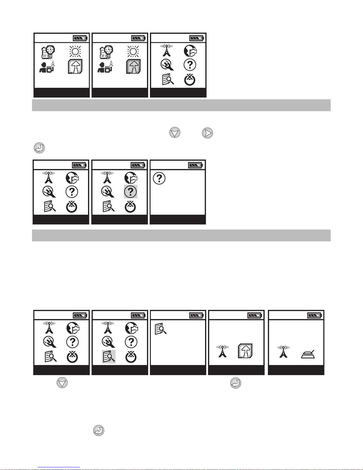
3. Setting the Handset ID and Client ID
First, set the Handset ID. Start by pressing to enter the menu, and then
press to navigate down to the HANDSET SETUP. Press to enter
10
Page 11
HANDSET SETUP icon. In the HANDSET SETUP screen a flashing lock
10:00 10:00 10:00 10:00
SETUP MENU HANDSET SETUP HANDSET SETUP HANDSET SETUP
HANDSET ID:
CLIENT ID:
HANDSET ID: XX
CLIENT ID: XXX
10:00 10:00 10:00
+
–
SETUP MENU CONTRAST CONTRAST
appears. Press to unlock. The first ID digit will then be flashing. To enter
a number (1-9) press or . Press and repeat the steps with the
second digit. Press to continue to the next step, setting a Client ID. To
select the first character, press or and repeat the steps for the second
and third characters. When finished, press to continue. We recommend
keeping a record of this information.
4. Adjusting Display Contrast
The contrast screen allows the user to adjust the contrast of the LCD display
for better viewing.
Press to enter the menu and press to navigate right to the CONTRAST
icon. Press to enter CONTRAST icon. Press or to adjust the
desired contrast level. When finished, press to continue.
5. Exit Setup Menu
To Exit SET UP press or and select the EXIT icon. Press to return
to the MAIN MENU screen.
11
Page 12
10:00 10:00 10:00
SETUPMENU EXIT MAINMENU
2.5 Help
If help is needed, DIG's contact information is listed under the HELP icon.
To navigate to the HELP icon, press and . To enter HELP screen press
. The DIG contact information is available for review.
10:00 10:00 10:00
800-322-0146
760-727-0914
WWW.DIGCORP.COM
MAIN MENU HELP HELP
2.6 Connecting to a LEIT-2 via FIND
The find icon quickly connects to a LEIT-2 controller that has been accessed
with the handset previously. This option allows easy identification and
connection to the last 10 controllers on the system that have been
communicating with the handset. The find screen also provides an address or
description (if entered in the controller setup) making it easy to identify the
controller location.
10:00 10:00 10:00 10:00 10:00
ARE YOU SURE?
CONTROL ID: XX
DESCRIPTION
MAIN MENU FIND FIND YES/NO
CONNECTING
CONNECT
Press to navigate down to FIND icon and press to enter the FIND
screen. In the FIND screen, the controller ID is flashing. To select a controller
ID to connect to, scroll through and select a Controller ID from one of the last
10 saved controller addresses (if available). After the Controller ID has been
selected, press to connect. After linking to a LEIT-2 controller, status
12
Page 13
information can be reviewed if available. When the Controller Menu appears
it is available for programming and reviewing.
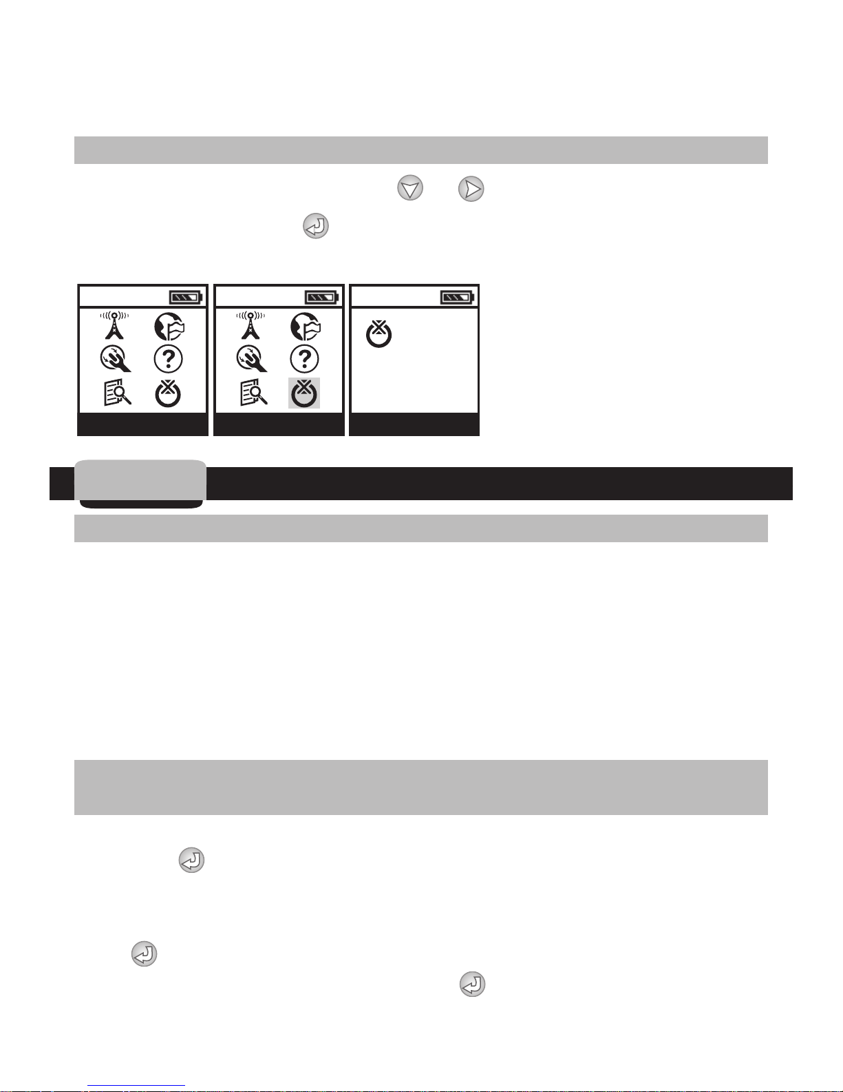
2.7 Turn Off the Handset
Select the TURN OFF icon using the or buttons. When the TURN OFF
icon is highlighted, press to turn off the handset. If the handset is left on,
it will turn off automatically after 10 minutes.
10:00 10:00 10:00
TURN OFF
MAIN MENU TURN OFF TURN OFF
3. Initial communication
3.1 Setup Steps to Initiate Communication for the First Time
First, let the LEIT-2 controller sit out in bright light to harness light energy used
to power the controller. This will take about 30 minutes or less in direct
sunlight. Next, connect the 2 yellow-colored sensor wires on the LEIT-2
controller to signal to the controller that it is about to be programmed. Splice
the 2 yellow sensor wires together using waterproof connectors. This splice
will distinguish that the controller is ready to communicate with a LEIT RC2
handset. Connect to the controller via the handset RADIO UPLINK icon using
the default address.
3.2 Connecting to the LEIT-2 controller for the first time using the
LEIT RC2 handset
In the LEIT RC2 handset's main menu press and highlight the RADIO UPLINK
icon. Press and the RADIO UPLINK screen will appear with default setup.
The description in this screen is: CONTROL ID: 00, DEFAULT SETUP with the
first Ø flashing.
Press to connect to the controller. The ARE YOU SURE? screen will appear
with the Radio Uplink icon selected. Press to connect to the controller
without an ID. After establishing communication, CONNECTED will appear
13
Page 14
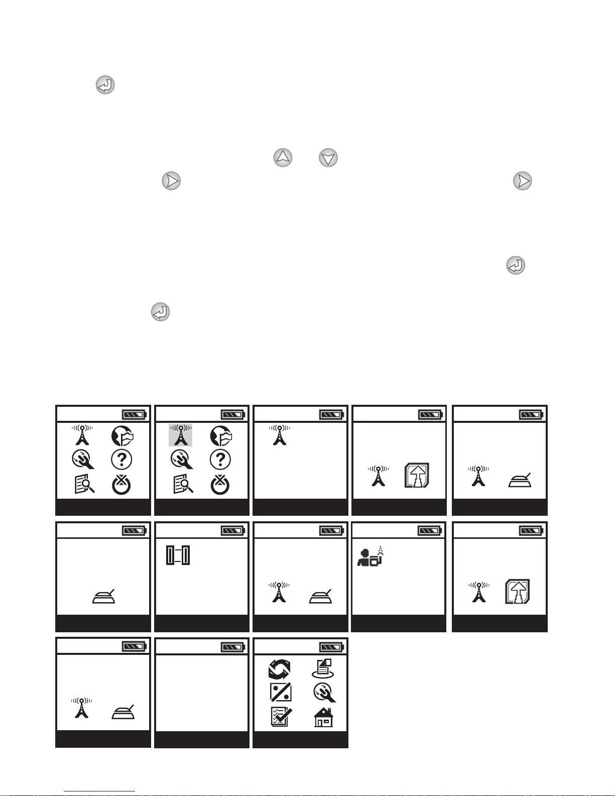
momentarily and then, CONNECTED TO: CONTROLLER ID: 00, DEFAULT SETUP.
Press again. The UPLOADING screen appears momentarily then, CONT.
SETUP with CONTROL ID: XX (digits flashing), which means the controller's ID
is available for modification.
To modify the controller ID, press or and enter a number (1-9) for the
first digit. Press and repeat the steps with the second digit. Press to
continue to the next step, setting controller address (the default is NODESCRIPTION). Repeat the steps for entering a controller address. The final
step is selecting a new Client ID (A-Z) (this is a security feature). The default
ID is AAA. Repeat the steps to select a new ID. When finished, press to
connect and upload the new information. The ARE YOU SURE? screen will
appear. Press again to download the information. The UPDATE
SUCCESSFUL message will appear momentarily confirming that controller
setup is updated and complete and then, the controller menu appears.
The controller is ready to program:
NOTE: Client ID on the controller must be the same as the handset.
10:00
MAIN MENU
10:00
CONNECTED
CONNECT
10:00
10:00 10:00 10:00
ARE YOU SURE?
CONTROL ID: XX
NO DESCRIPTION
RADIO UPLINK RADIO UPLINK YES / NO
10:00
<
>
CONTROL ID: XX
NO DESCRIPTION
CONNECTED TO
10:00
10:00
CONNECT
10:00
10:00
CONTROL ID: XX
NO DESCRIPTION
CLIENT ID: XXX
CONT. SETUP
10:00
CONNECTING
CONNECT
10:00
ARE YOU SURE?UPLOADING
YES / NO
CONNECTING
CONNECT
UPDATE
SUCCESSFUL
CONNECT
CONTROLLER MENU
14
Page 15
The user can now easily connect to this controller using the newly assigned
Controller ID and Client ID. Repeat the steps to program additional
controllers.
Attention: The two (2) yellow or yellow and black sensor wires are left
connected, so the RAIN OFF alert will not appear. If a rain sensor needs to be
added, see Sensor Installation in the LEIT-2ET controller instruction manual.
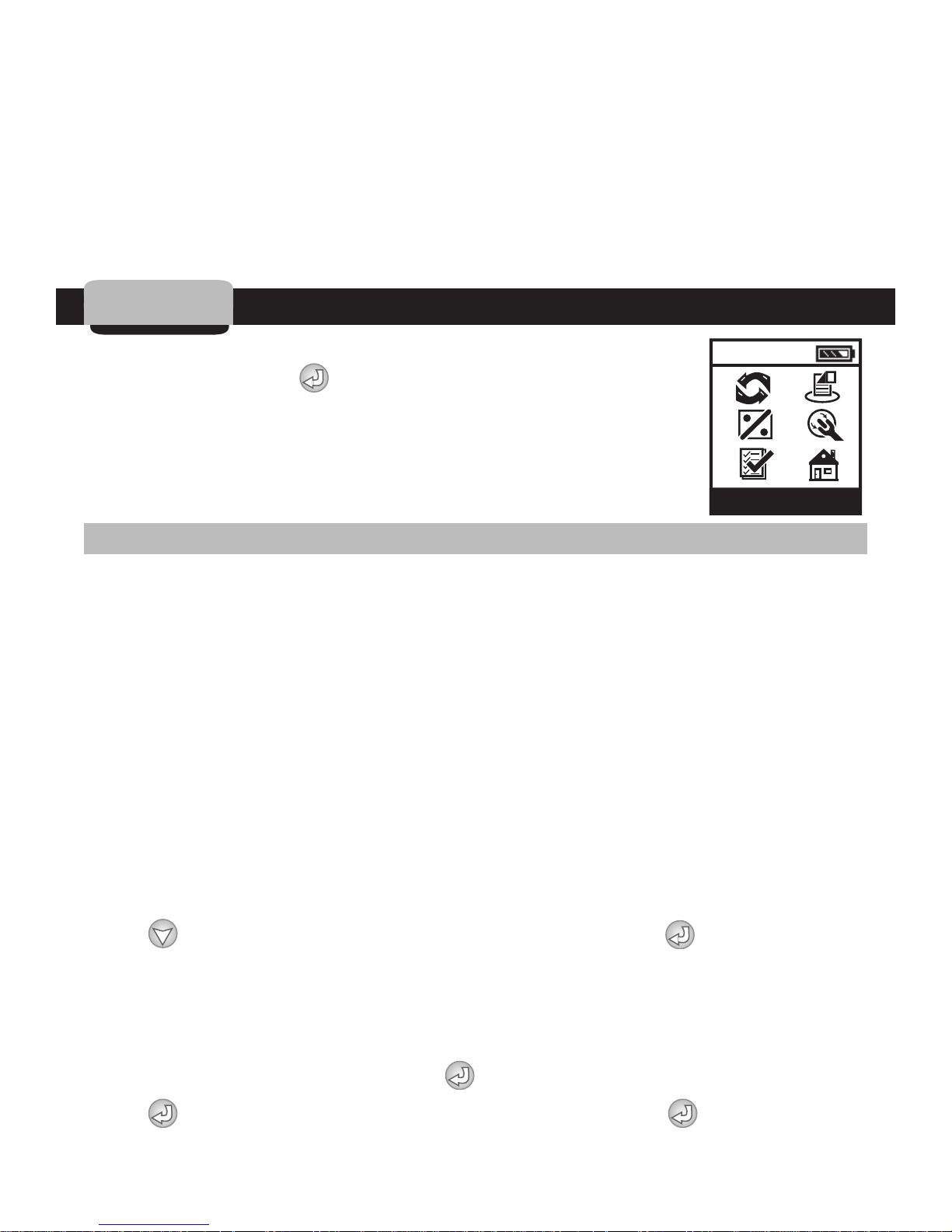
4.
After establishing communication with a LEIT-2 controller,
Controller Menu
10:00
continue by pressing . Screens displaying the controller's
ID and status are displayed until the controller menu
appears. In the Controller Menu any of the LEIT-2 features can
be reviewed or modified.
CONTROLLER MENU
4.1 Manual Run
The first option available on the controller menu is to perform a remote
Manual Run, if needed. Other options are available at this time, such as the
Global Off command, which turns off all controllers with the same ID within
operating distance of the handset.
Manual Run is useful for checking the proper operation of stations (especially
after installation), for applying additional water for a defined irrigation period,
or repeat testing of any individual valve using manual test icon.
The Manual Run feature can be used to test a selected valve, make a
temporary program or skip any valve as needed. Manual run has a priority over
a program and will suspend a program or valve-watering schedule. Note that
at the completion of Manual Run, any programmed irrigation schedule reverts
back to normal operation.
Press and navigate to the MANUAL RUN icon. Press to en
MANUAL RUN menu screen. Use the same procedures to select other options
as needed.
1. Manual Test
In the controller menu screen press and highlight the MANUAL RUN icon.
Press to enter the MANUAL RUN menu screen. Press and highlight
ter
15
Page 16
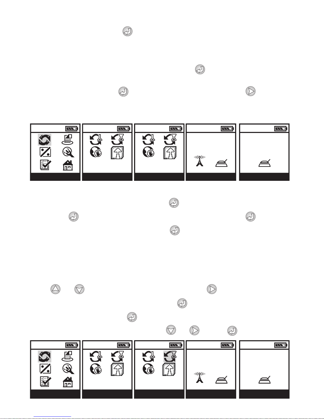
MANUAL TEST icon. Press to connect. If the controller is active,
10:00
10:0010:00 10:00
10:00
MANUAL RUN CONNECT
CONNECT
UPLOADING
CONNECTED
MANUAL RUN MENU MANUAL TEST
10:00
10:0010:00 10:00
10:00
MANUAL RUN CONNECT
CONNECT
UPLOADING
CONNECTED
MANUAL RUN MENU MANUAL TEMP
a screen will display that a program is running. In order to use the manual test
feature, the program(s) that is running needs to be suspended. After the
program is suspended, the manual test screen will appear with the valve
number and the words TURN ON flashing. Press to turn on Valve #1 and a
screen confirming that the valve is turned on appears.
To turn off Valve #1 press . After turning Valve #1 off, press to skip to
Valve #2 or to exit. Repeat the steps for each valve as needed.
If the valve is not turned off, it will turn off automatically after 3 minutes.
2. Manual Temp
In the CONTROLLER MENU screen press and highlight MANUAL RUN
icon. Press to enter the MANUAL RUN menu screen. Press to
highlight the MANUAL TEMP icon. Press to connect. If the controller is
active, a screen will display that a program is running. In order to use manual
temp the programs that are running need to be suspended. After the program
is suspended, the manual temp screen will appear with the valve number and
the hour digits flashing.
Press or and set the hour digits, then press and set the minute
digits. Repeat the steps for Valve #2. Press to connect. The ARE YOU
SURE screen appears. Press again to initiate a temporary program. When
finished select the exit icon by pressing or . Press to exit.
16
Page 17
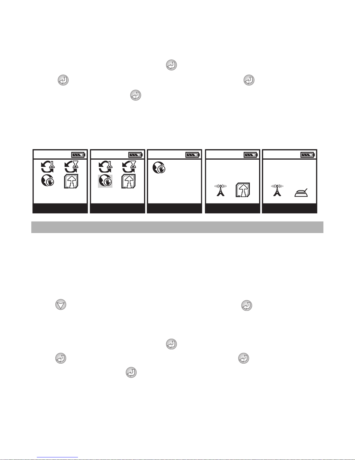
3. Global Stop – Stops Irrigation of all LEIT-2 Controllers Within Range
10:00 10:00
10:00 10:00 10:00
MANUAL RUN MENU GLOBAL STOP GLOBAL STOP YES / NO CONNECT
ARE YOU SURE? CONNECTING
STOP FOR
XX DAYS
of the RC2 Handset
In the controller menu screen press to highlight the MANUAL RUN icon.
Press and enter MANUAL RUN menu screen. Press and highlight the
GLOBAL STOP icon. Press to connect. If more than one
controller is in range the signal may take a few seconds. Within the handset
range, all the LEIT-2 controllers with the same Client ID will stop for 1 day. The
controller menu will appear on the handset.
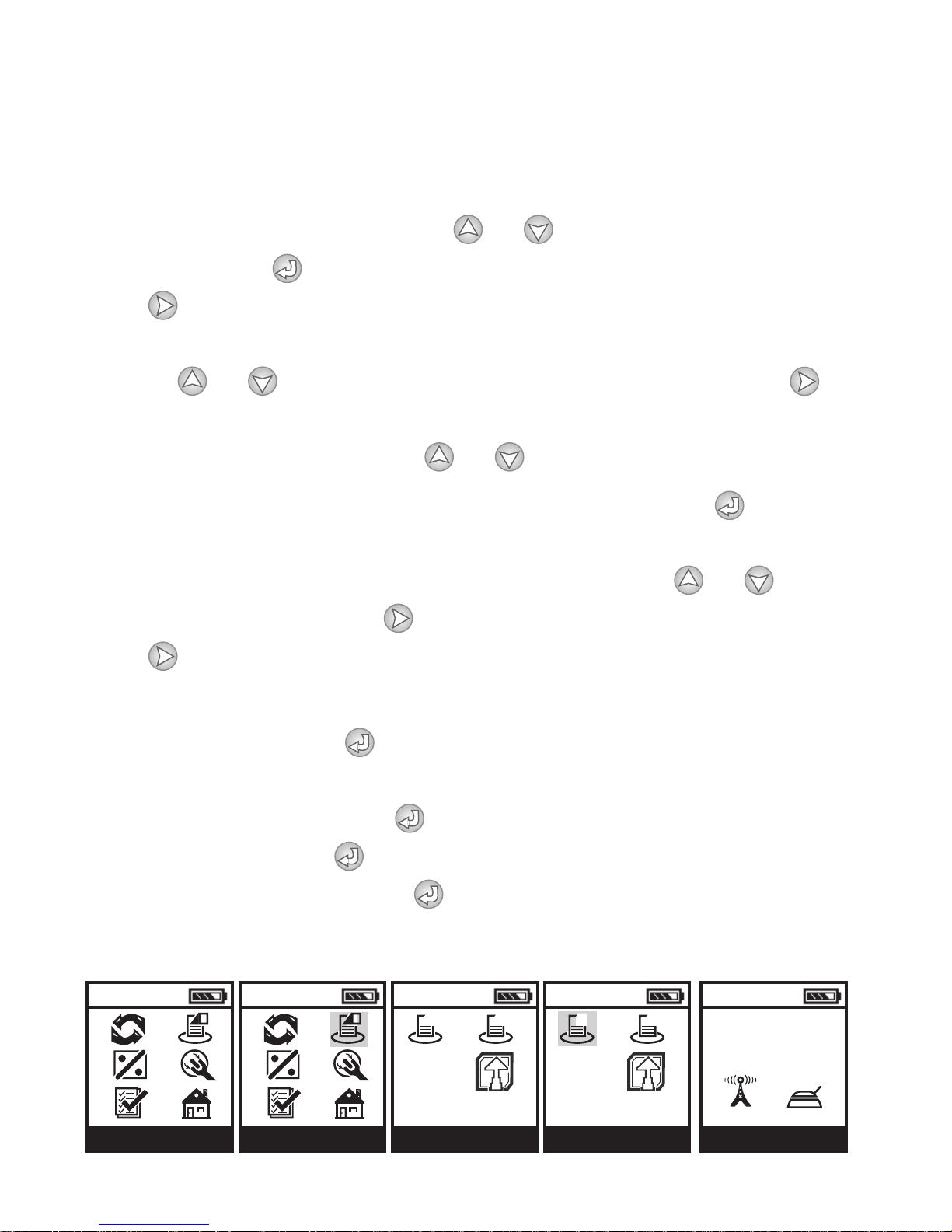
4.2 Setting or Changing a Program
This feature allows the user to review, change or set a schedule with up to
two separate programs for each station. Each valve can be programmed with
odd, even, and up to every 30 days. Each program has up to 4 individual start
times per day with durations up to 5 hours and 59 minutes in 1-minute
increments for each valve. At the end of the setting the handset also displays
the next time a program will operate.
Press and navigate to the PROGRAM A icon. Press to enter
PROGRAM A. Use the same procedures to make any adjustments, as needed.
Repeat the steps for PROGRAM B as needed or exit the Program Menu.
In the controller menu screen press and highlight the PROGRAM icon.
Press to enter the PROGRAM MENU screen. Press and highlight the
PROGRAM A icon. Press to connect. After establishing
communication, CONNECTED will appear momentarily and then the
PROGRAM A, SELECT DAYS screen appears with SELECT DAYS flashing. In
each program the following options are available:
17
Page 18
Every: Enables the stations to operate from once a day to once every 30 days
10:0010:00 10:0010:00
A B
10:00
A B
CONTROLLER MENU PROGRAM MENU PROGRAM APROGRAM CONNECT
UPLOADING
Odd: Every odd number of days
Even: Every even number of days
MTWTFSS: Select specific day(s) of the week
To select the preferred option, press or . If ODD DAYS or EVEN DAYS
was chosen press to select. If MTWTHSS or EVERY DAY was chosen
press to select. The underscore above M or the number of days will flash.
In the SELECT DAYS (MTWTHSS) screen, select the preferred watering days
by using or . A drop will appear above the day selected. Press to
repeat the steps for setting additional watering days. To change the number of
days in EVERY DAY screen, press or .
Up to 4 start times can be selected including AM or PM. Press and the
START TIME screen appears with start #1 OFF flashing. To program the start
time first, change the hour digit including AM or PM using or . To
select the minute digit, press and repeat the step changing the minute.
Press and repeat the steps for start times 2, 3 and 4 or as needed.
Duration can be set from 1 minute and up to 5 hours and 59 minutes in 1minute increments. Press and the DURATION screen apears with Valve #1
and the hour digits flashing. Use the same steps to set duration for Valve #1
and #2. Once completed press and information with the next start time
schedule appears. Press to download the new information. The ARE YOU
SURE? screen will appear. Press to connect and the UPDATE SUCCESSFUL
message appears. Then the Setup Menu appears again.
18
Page 19
4.3 Setting a Monthly Budget
10:00 10:00
10:00
10:00
10:00
10:00
10:0010:0010:00
CONNECT
CONNECTED
SELECT DAYS
CONNECT
CONNECT
DOWNLOADING
CONNECT
UPDATE
SUCCESSFUL
CONNECTED
YES / NO
ARE YOU SURE?
PROGRAM: A
SELECT DAYS
X _ _ X X _ _
M T W T F S S
NEXT SCHEDULED
NEXT SCHEDULED
START TIME
XX:XX
XX DAYS
DURATION
PROGRAM: A
XX:XX
XX:XX
START TIME
PROGRAM: A
1 9:00 AM
2 10:00 AM
3 11:00 AM
4 OFF
10:00
10:00
10:00 10:00
10:00
CONTROLLER MENU BUDGET CONNECT
CONNECT
UPLOADING
CONNECTED
BUDGET
JAN 100%
FEB 100%
MAR 100%
APR 100%
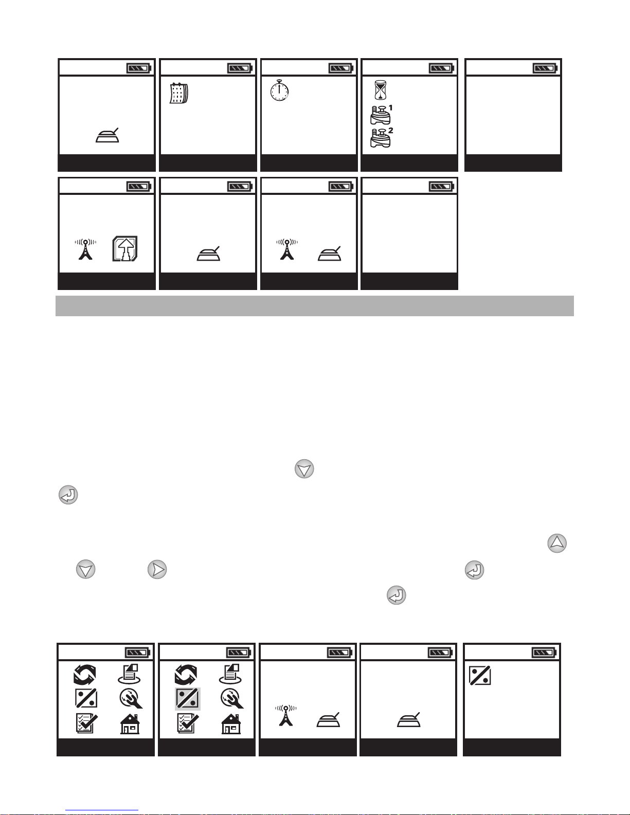
The amount of irrigation water applied during seasonally dry or wet periods
changes throughout the year. Instead of changing the duration for each
program on a monthly basis, the Budget feature can be utilized to reflect the
seasonal changes. Budgeting is programmed once to increase or decrease the
irrigation on a monthly basis for an entire year. Budget adjustments can range
from 10 -200% in 10% increments. The controller will automatically adjust the
previously programmed durations according to the specified budget.
In the controller menu screen press and highlight the BUDGET icon. Press
to enter the BUDGET screen. After connected, the budget screen appears
with the first 4 months of the year. The words JAN 100% will be flashing. To
increase or decrease the budget percentage (in increments of 10%), press
or . Press and repeat the steps for each month. Press to move to
the next screen and repeat. When finished, press to download the new
information.
19
Page 20
4.4 Controller Setup
10:00
10:00
10:00 10:00
10:00
CONNECT
CONNECT
DOWNLOADING
BUDGET
MAY 100%
JUN 100%
JUL 100%
AUG 100%
BUDGET
SEP 100%
OCT 100%
NOV 100%
DEC 100%
UPDATE
SUCCESSFUL
YES / NO
ARE YOU SURE?
10:00
10:00
10:00 10:00 10:00
CONTROLLER MENU CONNECT
DOWNLOADING
SETUP MENU SET TIME / DATE SET TIME / DATE
10:00:00 AM
MONDAY
7/10/2006
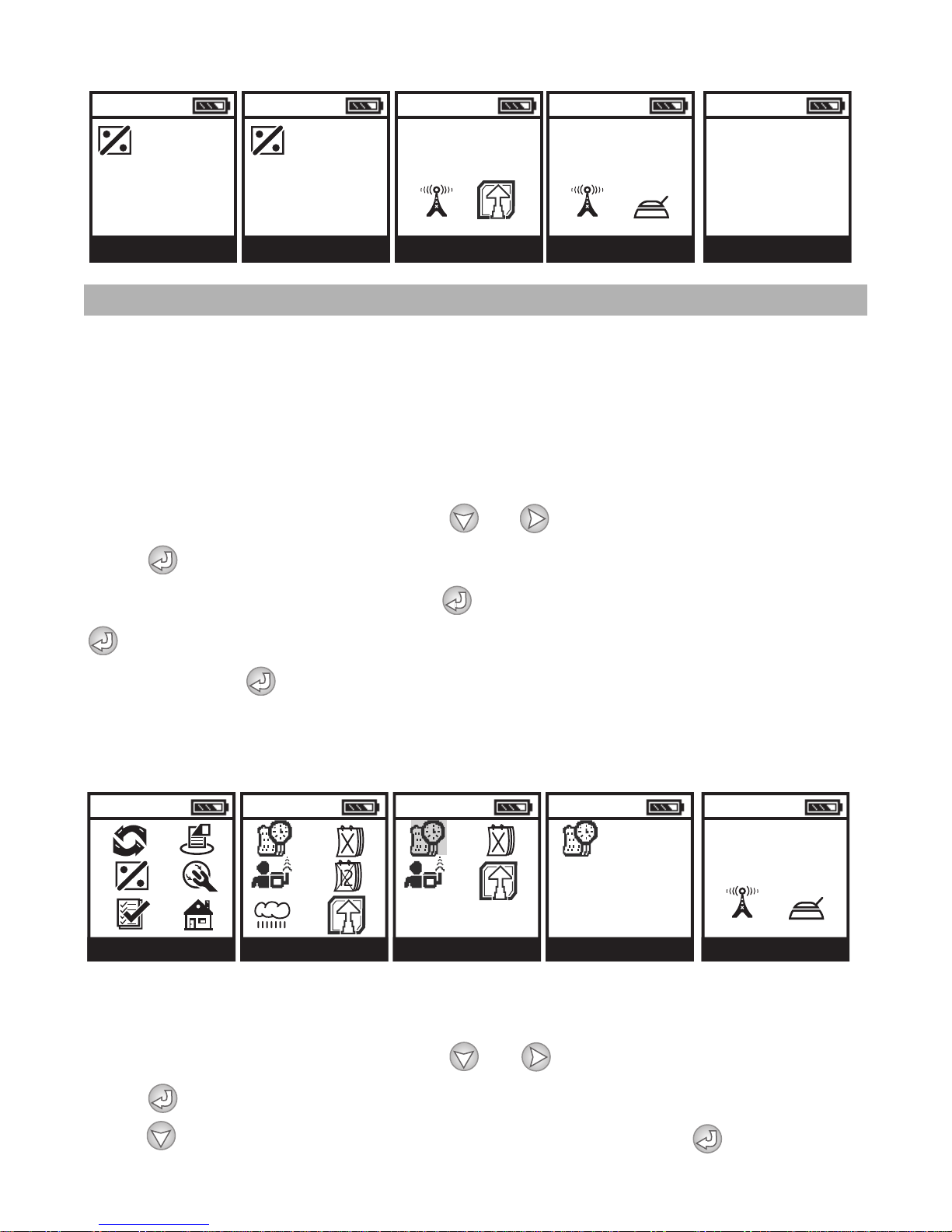
In the controller menu the user can setup the controller's current time
and date, change controller ID, and Client ID numbers, add an address,
set a rain delay, month off and events off. The information in Setup
Menu can be updated or changed as needed.
1. Set Time and Date
In the controller menu screen, press or and highlight the SETUP icon.
Press to enter SETUP MENU screen. In the SETUP MENU screen highlight
the SET TIME/DATE icon and press to enter the TIME/DATE screen. Press
again to upload the current time and date, the ARE YOU SURE icon
appears. Press again to download the information to the controller. If the
time and date setup is completed the UPDATE SUCCESSFUL message appears
then, Setup Menu appears again.
2. Setting or Changing Controller ID, Client ID and Adding a Descriptive
Address
In the controller menu screen, press or and highlight the SETUP icon.
Press to enter the SETUP MENU screen. In the SETUP MENU screen,
press and highlight the CONTROLLER SETUP icon. Press to enter the
20
Page 21
CONTROLLER SETUP screen. The handset is connecting to the controller. After
10:00
10:00
10:00
10:00
10:00
SETUP MENU
CONTL. SETUP
CONNECT
UPLOADING
CONNECT
CONNECTED
CONTL. SETUP
CONTROL ID:
CLIENT ID:
10:00
10:00 10:00
10:00 10:00
SETUP MENU
CONTL. SETUP CONNECT
UPLOADING
CONNECT
CONNECTED
RAIN OFF
STOP FOR
XX DAYS
connection is established the CONTROLLER SETUP screen appears with a lock
on the right flashing. Press to unlock the lock. The first HANDSET ID digit
is flashing. To enter a number (1-9) press or . Press and repeat
the steps with the second digit. Press to continue to the next step,
setting controller address. Repeat the steps selecting controller address. Then
change the Client ID using the same steps.
When finished, press to connect and download the new information. The
ARE YOU SURE icon will appear. Press again to download the
information. The UPDATE SUCCESSFUL message appears confirming that
controller setup is updated and complete and then, Setup Menu appears.
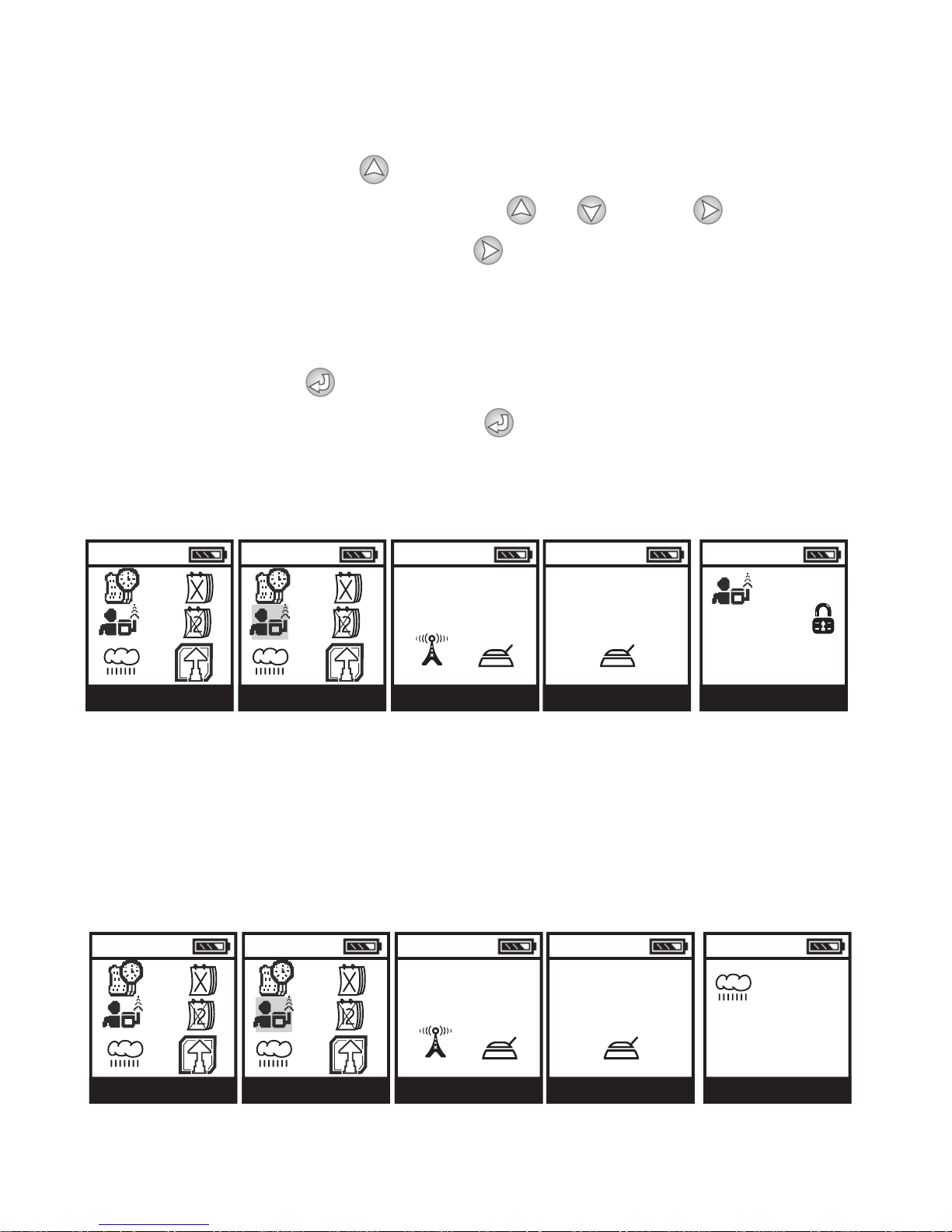
3. Setup Rain Stop
The Rain Stop option is used to temporarily suspend all irrigation programs.
For example, during rainy weather regularly scheduled programs can be turned
off. The Rain Stop feature allows the user to pause irrigation from 1-99 days.
At the end of the designated period, regularly scheduled programming will
resume automatically.
21
Page 22
In the controller menu screen, press or and highlight the SETUP icon.
10:00
10:00 10:00
10:00 10:00
SETUP MENU
CONTL. SETUP CONNECT
UPLOADING
CONNECT
CONNECTED
EVENTS OFF
1: 12/03
2: 09/14
3: OFF
Press to enter the SETUP MENU screen. In the SETUP MENU screen,
press and highlight the RAIN STOP icon. Press to enter the RAIN OFF
screen. The handset will connect to the controller. After connection is
established, the RAIN STOP screen appears with the XX of days flashing. To
set the number of days to stop watering, press or . When finished,
press to connect and download the information. The ARE YOU SURE
screen appears. Press again to download the information. The UPDATE
SUCCESSFUL message appears confirming that the controller accepted the
new information and then, Setup Menu appears. Rain Stop can be cancelled
at any time by re-entering Rain Stop screen and changing the setting to 0.
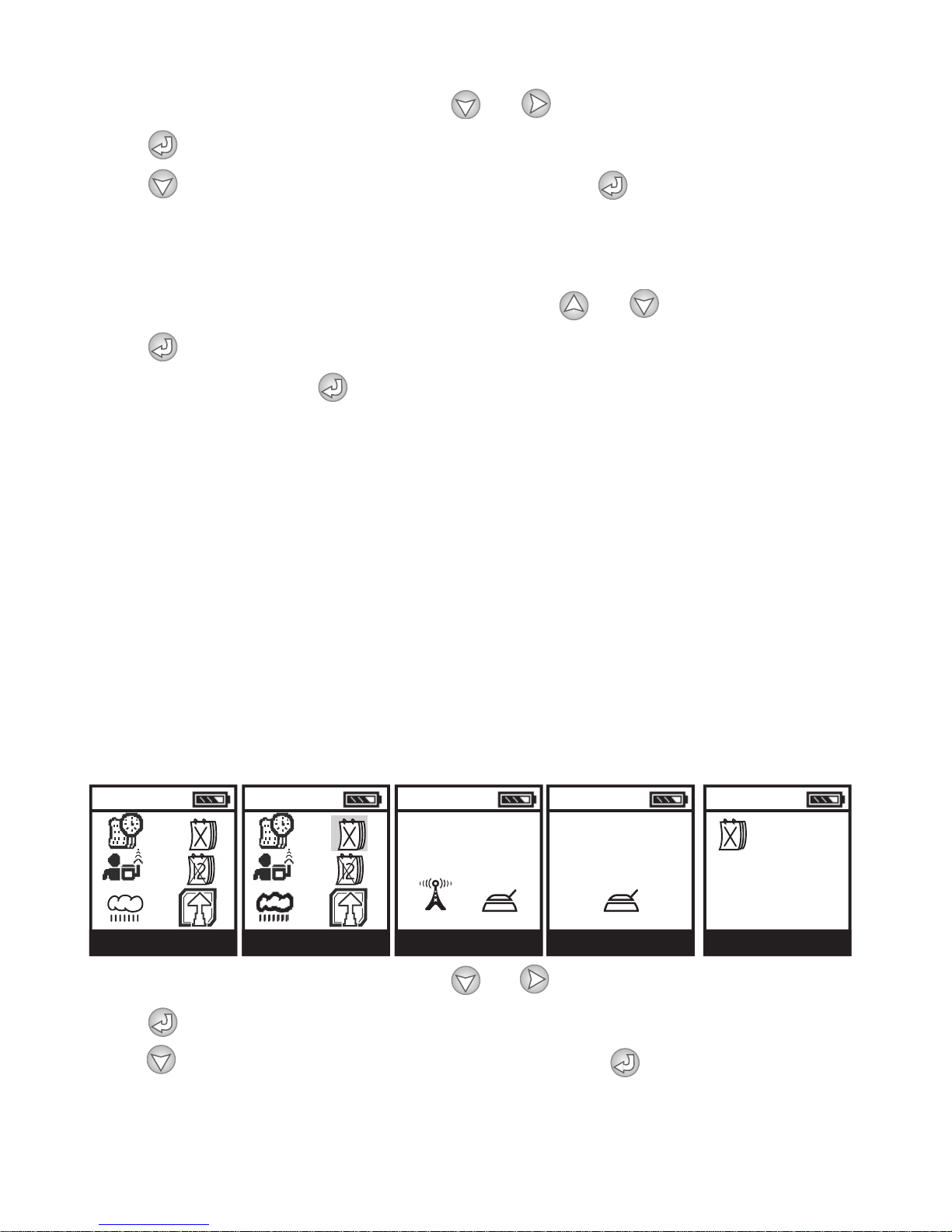
4. Setting Event Off
The Event Off option is used to suspend all irrigation programs for specific
days of the year. For example, during a holiday one could stop regularly
scheduled programs from watering. The Event Off feature allows the user to
pause irrigation for up to 3 days. Regularly scheduled programming will
resume automatically after Event Off has expired. Event off needs
programming once and then will remain active for years to come, unless
changed by the user.
In the controller menu screen, press or and highlight the SETUP icon.
Press to enter the SETUP MENU screen. In the SETUP MENU screen,
press and highlight the EVENTS OFF icon. Press to enter the EVENTS
OFF screen. The handset will connect to the controller. After connection is
22
Page 23
established, the EVENTS OFF screen appears. The first option DAYS OFF is
10:00
10:00
10:00 10:00
10:00
10:00
10:00 10:00
10:00
10:00
CONNECT
DOWNLOADING
SETUP MENU
CONTL. SETUP
CONNECT
UPLOADING
CONNECT
CONNECTED
MONTH OFF
JAN ACTIVE
FEB ACTIVE
MAR ACTIVE
APR ACTIVE
MONTH OFF
MAY ACTIVE
JUN ACTIVE
JUL ACTIVE
AUG ACTIVE
MONTH OFF
SEP ACTIVE
OCT ACTIVE
NOV ACTIVE
DEC ACTIVE
YES / NO
ARE YOU SURE?
CONNECT
UPDATE
SUCCESSFUL
flashing. Press or to enter a date then press to get to the second
date. Repeat the steps with the second and third options. When finished,
press to connect and upload the information. The ARE YOU SURE icon will
appear. Press again to download the information. The UPDATE
SUCCESSFUL message appears confirming that the controller accepted the
new information and then, Setup Menu appears again.
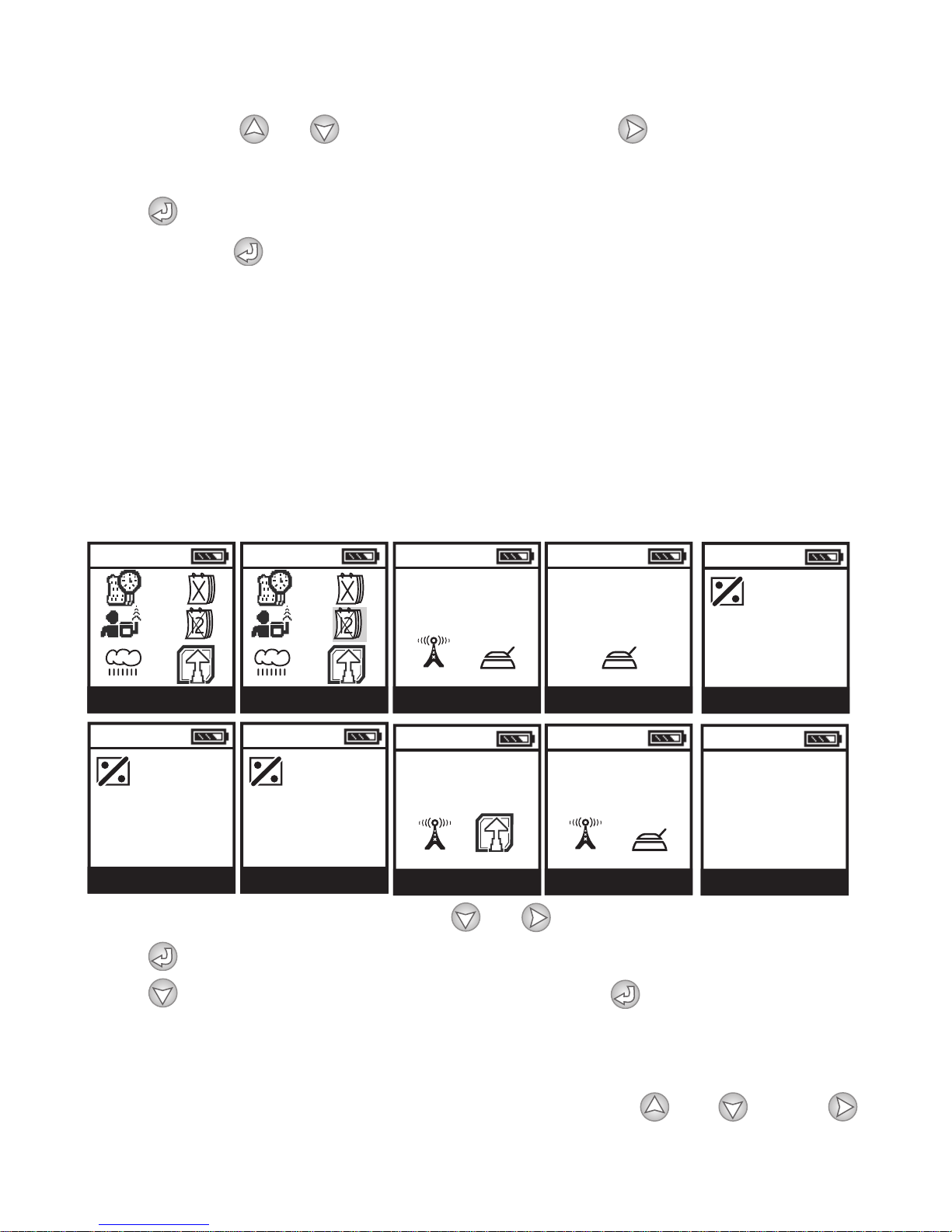
5. Setting Month Off
The Month Off feature allows the user to suspend all irrigation programs for
any specific month of the year. For example, during the month of December
you can stop regularly scheduled programs from watering. Regularly
scheduled programming will not run in the month that has been deactivated.
The controller will resume its normal operations in the active months.
In the controller menu screen, press or and highlight the SETUP icon.
Press to enter the SETUP MENU screen. In the SETUP MENU screen,
press and highlight the MONTH OFF icon. Press to enter the MONTH
OFF screen. The handset will connect to the controller. After connection is
established, the MONTH OFF screen appears with the words ACTIVE flashing
near the month of JAN. To deactivate the month, press or . Press
23
Page 24
and repeat the steps with any other month. When finished, press to
10:00 10:00
10:00
10:00 10:00
CONTROLLER MENU REPORTS CONNECT
UPLOADING
REPORT MENU PROGRAM STATUS
connect and download the information. The ARE YOU SURE icon will appear.
Press again to download the information. The UPDATE SUCCESSFUL
message appears confirming that the controller accepted the new information
and then, Setup Menu appears again.
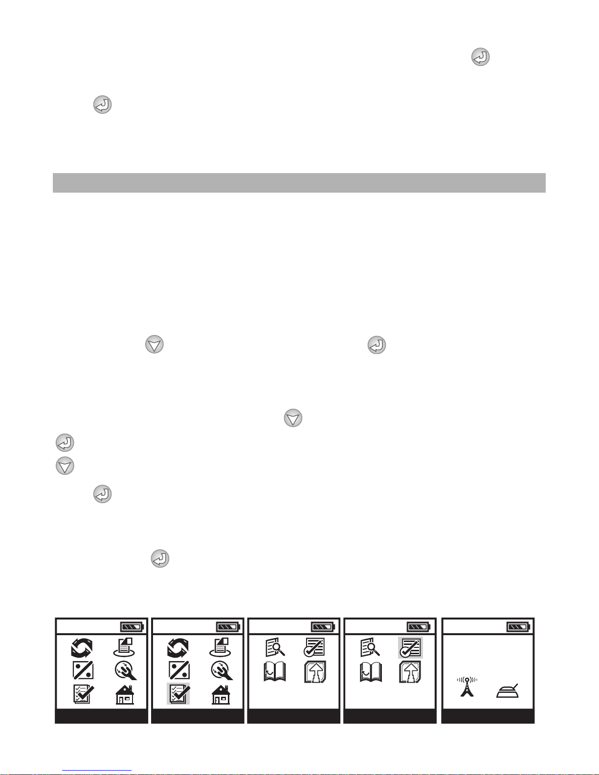
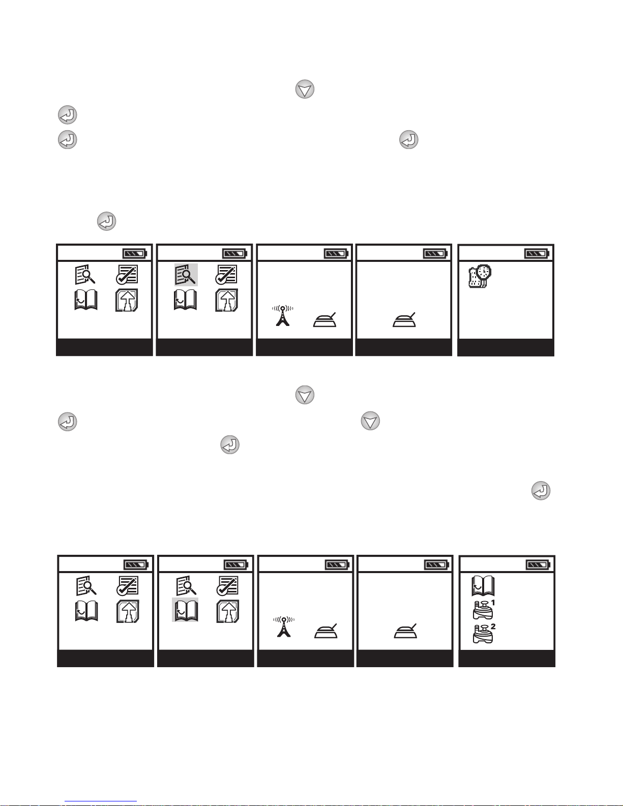
4.5 Reports menu
The Controller Report menu allows the user to review a controller's program
status including changes made to the program, budget, events off, rain off or
month off. The handset that made the changes can also be identified. In
Current Status the user can review any active features such as time, date, or
active manual runs. Current Status also notifies the user if there is a short or
open circuit in valve wiring, the power level in the controller and the external
temperature around the controller. In History Reports the user can review the
time each valve has been open for the current and last month. To review
Reports press to navigate to REPORTS. Press to enter and review up
to 3 reports.
1. Program Status
In the controller menu screen, press and highlight the REPORT icon. Press
to enter the REPORT MENU screen. In the REPORT MENU screen, press
and highlight the PROGRAM STATUS icon.
Press to enter the PROGRAM STATUS screen. The handset will connect to
the controller. After connection is established, the PROGRAM STATUS screen
appears with the first program change. Then the VIEW CHANGES screen
appears. Press to view the changes. The next few screens will show the
changes and the handset that made the modifications. Repeat the same steps
to view other changes. When finished the Program Status menu appears again.
24
Page 25
2. Current Status
10:00
10:00
10:00 10:00
10:00
REPORT MENU CURRENT STATUS CONNECT
UPLOADING
CONNECT
CONNECTED
CURRENT STATUS
10:00:00 AM
MONDAY
7/10/2006
10:00
10:00
10:00 10:00
10:00
XX:XX
XX:XX
REPORT MENU HISTORY CONNECT
UPLOADING
CONNECT
CONNECTED
TOTAL THIS MONTH
In the controller menu screen, press and highlight the REPORT icon. Press
to enter the REPORT MENU screen. In the REPORT MENU screen, press
and highlight the CURRENT STATUS icon. Press to enter
the CURRENT STATUS screen. The handset will connect to the controller. After
connection is established, the CURRENT STATUS screen appears with the
current time and the date. To continue viewing the current controller activity
press . When finsihed the Program Status menu appears again.
3. History
In the controller menu screen, press and highlight the REPORT icon. Press
to enter the REPORT MENU screen, press and highlight
the HISTORY icon. Press to enter the HISTORY screen. The handset is
connecting to the controller. After connection is established, the HISTORY
screen appears with the TOTAL THIS MONTH for Valve #1 and #2. Press
again to view the TOTAL LAST MONTH for Valve #1 and #2. Repeat the same
steps to return to the Program Status menu.
25
Page 26
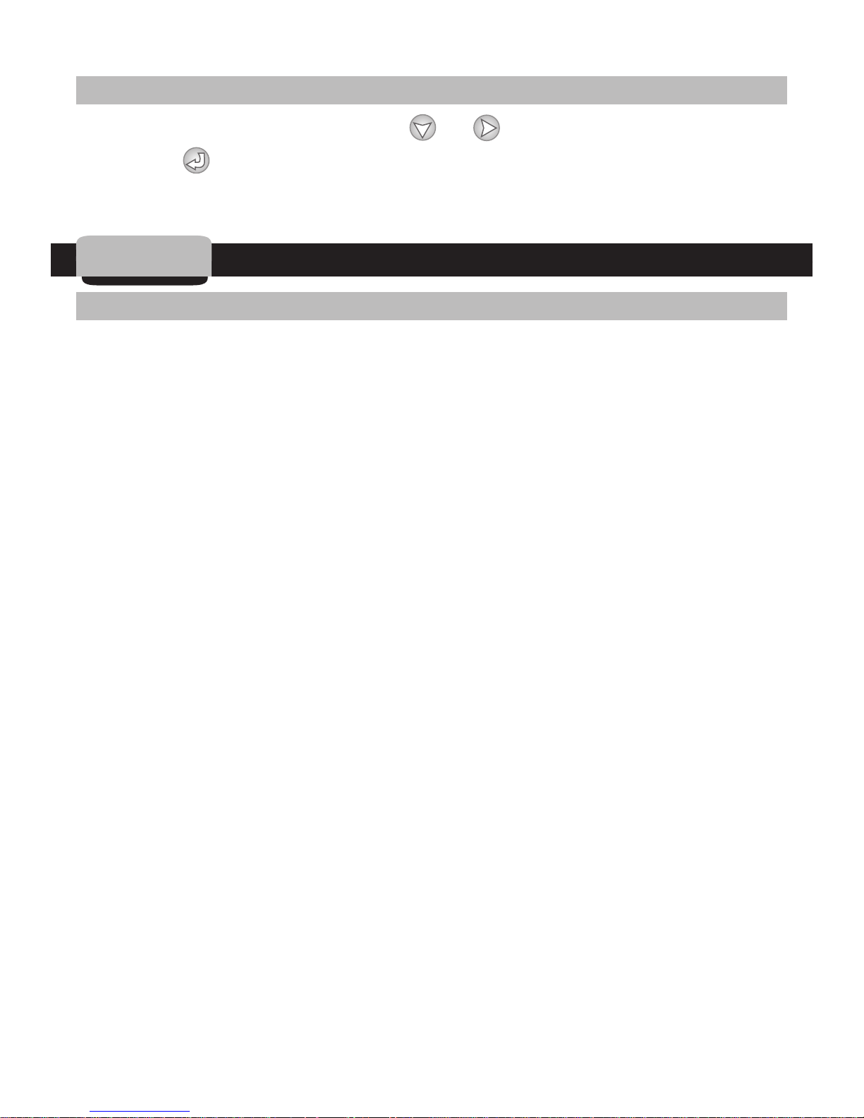
4.6 Exit Controller Menu
In the controller menu screen, press or and highlight the TURN OFF
icon. Press to enter the TURN OFF screen. The handset will turn off.
If the handset is left on, it will turn OFF automatically in 10 minutes.
5. Troubleshooting
5.1 General Information for Handset and Controller
1) The LEIT-2 wireless irrigation controller needs adequate light. The radio
cannot maintain proper functionality in a continually shaded position, such
as adjacent to a wall, unless it is on the "sunny" side of the wall. If light
levels drop too low the radio will turn it off to guarantee correct controller
operation. When the radio is off, less power is used and the controller
charges faster. The radio's internal circuitry can turn itself on again when
sufficient light has charged the controller to adequate levels. At low light
levels the radio will periodically turn off.
2) The radio will function better if the controller is located at higher elevation.
If there is a choice do not situate the controller in a hollow.
3) To communicate, the controllers and handsets MUST have the same Client
ID Code. This
is the users unique identification code, which prevents
interference from other users in the area.
4) If two controllers are set to the same ID, communication may be disrupted if
both controllers are in range of the handset. The same occurs if two
handsets are set to the same ID and are in use at the same time. All
controllers and handsets in the same group must have a unique ID.
5) The handset needs to be kept in a charged state. After 500-1000 charge
cycles the internal batteries may need replacement.
IMPORTANT:
controllers are automatically limited to daylight hours between 8 AM to 5 PM,
when there is sufficient light energy. Longer bright light days will enable the
radio to operate automatically over longer parts of the day, including through
the night.
Communication between the LEIT RC2 handset and the LEIT-2
26
Page 27

5.2 Programming Problems
Causes: The valves will turn on using the "Manual Run" feature but will
not water automatically. Check the following:
Solution:
1) The Rain Stop is active. To reactivate the program schedule, go into the
Main Menu-Rain Stop/Restart and cancel Rain Stop (see Programming,
page XXXXXXXX).
2) Check the date and time on the controller to make sure that it is the same
as the handset.
3) No programming schedules have been entered yet. In Controller Menu,
select program and Setup a Schedule.
4) The programmed runtime of the stations is set to "0" duration. Go into
Controller Menu, select the program and alter runtime.
5) A sensor is hooked up to the system that is inhibiting irrigation or sensor
wires are not connected if sensor added.
6) If the valves operate correctly in a manual run but not in a scheduled
program, check that the following settings are correct:
• Review the programs
• Sensor is active
• Month stop - turn off Month off and Month Selection screens
• Schedule start times, runtimes per program set correctly
7) If a program runs but starts unexpectedly check the schedule settings. If a
new program starts before the old program has completed it will be stacked
to commence later.
8) Make sure there is enough time between the programs and/or start times
to meet your watering time in budget (up to 200% possible)
Causes: No communication
Solution:
1) Check that the controller PVM (solar) panel is not covered. If it has been
covered for an extended period, the controller time will reset.
5.3 The Password has been Changed or Forgotten:
Please call DIG Customer Service with the serial number of the controller.
27
Page 28

6. Warranty
DIG CORPORATION warrants these products to be free from defects in material and workmanship for
a period of three years from date of purchase. This warranty does not cover damage resulting from
accident, misuse, neglect, modification or improper installation. This warranty shall extend only to
the original purchaser of the product for use by the purchaser. This warranty shall not cover batteries
or any malfunction of the product due to battery failure. The obligation of DIG CORPORATION under
this warranty is limited to repairing or replacing at its factory this product which shall be returned to
the factory within three years after the original purchase and which on examination is found to
contain defects in material and workmanship.
DIG CORPORATION SHALL IN NO EVENT BE LIABLE FOR ANY INCIDENTAL OR CONSEQUENTIAL
DAMAGES OF ANY KIND; THE SOLE OBLIGATION OF DIG BEING LIMITED TO REPAIR OR
REPLACEMENT OF DEFECTIVE PRODUCTS. SOME STATES DO NOT ALLOW THE EXCLUSION OR
LIMITATION OF INCIDENTAL OR CONSEQUENTIAL DAMAGES, SO THE ABOVE LIMITATION OR
EXCLUSION MAY NOT APPLY TO YOU.
Unattended use for prolonged periods without inspection to verify proper operation is beyond the
intended use of this product, and any damage resulting from such use shall not be the responsibility
of DIG CORPORATION. There are no warranties which extend beyond the description on the face
hereof. In the case of purchase of the product for use other than, for irrigation purposes, DIG
CORPORATION hereby disclaims any implied warranties including any warranties of merchantability
and fitness for a particular purpose. In the case of the purchase of the product for personal, family or
household purposes, DIG CORPORATION disclaims any such warranties to the extent permitted by
law. To the extent that any such disclaimer or implied warranties shall be ineffectual, then any
implied warranties shall be limited in duration to a period of three years from the date of the original
purchase for use by the purchaser. Some states do not allow limitation on how long an implied
warranty lasts, so the above limitation may not apply to you.
In order to obtain performance under this warranty, the unit must be returned to the factory, along
with proof of purchase indicating original date of purchase, shipping prepaid, addressed as follows:
DIG CORPORATION, 1210 Activity Drive, Vista, CA 92081-8510. Repaired or replaced units will be
shipped prepaid to the name and address supplied with the unit returned under warranty. Allow four
weeks for repairs and shipping time. Repair of damaged units not otherwise within warranty may be
refused or done at a reasonable cost or charge at the option of DIG CORPORATION.
This warranty gives you specific legal rights, and you may also have other rights which vary from
state to state.
1210 Activity Drive
Vista, CA 92081-8510, USA
Website: E
www.digcorp.com
e-mail: [email protected]
021710 DIG CORP 26-060
Printed in the USA
28
 Loading...