

Page 1

RECORD / CHART
LEIT Link®2-Way Radio Remote Control Handset
Instruction Manual
INSTRUCTION MANUAL
Website: E
http://www.digcorp.com
e-mail: [email protected]
041906 DIG CORP 26-401
Printed in the USA
1210 Activity Drive
Vista, CA 92081, USA
Controller Group
ID ID Location
1
2
3
4
5
6
7
8
9
10
11
12
13
14
15
16
17
18
19
20
21
22
23
24
25
26
27
28
Page 2

TABLE OF CONTENTS
INTRODUCTiON TO YOUR LEIT LINK ……………………………………………………………2
LEIT Link Handset Components ………………………………………………………………2
Setting Up the LEIT Link Handset and LEIT XRC Controller ……………………………………3
Communication Software Protocol …………………………………………………………3
Charging the Handset ………………………………………………………………………4
Setting Up the Handset………………………………………………………………………4
Communicating with a LEIT XRC Controller …………………………………………………6
Setting Up a Manual Run ……………………………………………………………………7
Setting Up Temporary Suspension of All Irrigation Programs …………………………………8
Setting Up a Monthly Budget for All Programs ………………………………………………9
Review a Controller Status …………………………………………………………………10
Review the Controller History Reports ………………………………………………………11
Review or Change the Programming Schedule………………………………………………13
Watering Calendar Option ……………………………………………………………13
Setting Start Time ……………………………………………………………………14
Setting Up Duration …………………………………………………………………14
Grouping Valves to Operate at the Same Time …………………………………………14
Setting the Controller System ………………………………………………………………16
Setting a Password …………………………………………………………………16
Setting the Time………………………………………………………………………16
Setting Date …………………………………………………………………………17
Setting the Radio Operation …………………………………………………………17
Setting Location Address ……………………………………………………………17
Activating Programs …………………………………………………………………17
Deactivating Any Month of the Year ……………………………………………………18
Activating for a Short or Open Wire ……………………………………………………18
Activating MV/P ………………………………………………………………………18
Activating Sensor ……………………………………………………………………18
Reviewing Radio Status ……………………………………………………………………20
Service Call (Installation Troubleshooting) …………………………………………………21
Troubleshooting Your Controller ……………………………………………………………21
Electrical Problems …………………………………………………………………21
Programming Problems ………………………………………………………………22
Grouping ……………………………………………………………………………22
Chart – Button Commands …………………………………………………Inside Back Cover
Copyright
Copyright 2005-2006 DIG Corporation. All rights reserved. LEIT and LEIT Link registered
trademarks. LEIT XRC, LEIT Link Master and LEIT Link Multi-Pro are each trademarks of DIG
Corporation.
FCC compliance
Important Note: To comply with FCC RF exposure compliance requirements, the antenna used for
this transmitter is installed to provide a separation distance of at least 8 inches (20 cm) from all
persons (not including hands, wrist, feet and ankles) and must not be co-located or operating in
conjunction with any other antenna or transmitter.
This device is required to comply with FCC RF exposure requirements for mobile and fixed
transmitting devices. This model transceiver generates and uses radio frequency energy. If not
installed and used in accordance with the manufacturer’s instruction, it may cause interference to
radio and television reception. The transceiver has been tested and found to comply with the
specification in part 15 of FCC rules for spread spectrum intentional radiators and FCC part 15
Subpart C, specification.
CAUTION: The user should make no field changes or modifications to the LEIT Link Remote Control
Handset or the LEIT Controller.
All adjustments and changes must be made at DIG’s facility under the specific guidelines set forth
in our manufacturing processes. Any change or modification to the equipment could void the users
authority to operate the unit, and render the equipment in violation of FCC part 15 subpart C,
15.247. Any tampering with this product will void the warranty.
Page 3
2
INTRODUCTION TO YOUR LEIT LINK
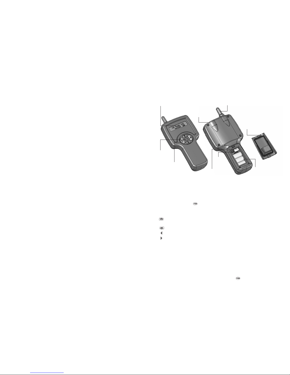
LEIT LINK HANDSET COMPONENTS
1. LCD Display
Displays the application stored in your handset.
2. Power Button
Turn your LEIT Link on or off .
3. Programming Buttons
Use these 4 buttons to program, modify,review and communicate with the LEIT XRC controller.
Use to accept and/or select the desired programming mode and raise (increase) the value of
the selected parameter.
Use to lower (decrease) the value of the selected parameter or de-select a check mark.
Use to move the cursor to left.
Use to move the cursor to right.
4. Antenna
See FCC compliance.
5. Battery Charge Outlets
The LEIT Link Remote Control Handset contains a cell battery pack that is rechargeable using the
AC/DC wall mounting battery charger 350 MA 12-volts, model 30-721. Plug the battery charger into
the LEIT Link handset for approximately 8 hours for an initial charge before using it. Then charge it
daily for a few hours as needed.
The charging screen will appear with +++Charging+++ 4.30V within one minute after the DC
charger is plugged in. The charging screen disappears when the button is pressed or the
charger is unplugged. A full charge will last for up to 3 hours of continuous use.The Battery Voltage
1
ABOUT THE LEIT LINK REMOTE CONTROL HANDSET
Thank you for purchasing DIG’s LEIT Link Remote Control Handset.This manual is designed to help
you get the LEIT Link handset up and running quickly.This manual will describe all you need to
know about how to use the LEIT Link handset. After you read this manual and have familiarized
yourself with the basic functionality of this device, you can use this manual as reference for less
common tasks in the future.
Models Available
• LEIT Link
®
Master™ operates 99 groups of controllers with up to 99 controllers per each group
• LEIT Link
®
Multi-Pro™ operates 99 controllers in one group
The LEIT Link Remote Control Handset is a 2-way radio communication device that operates in
the ISM band 902-928 MHz (868/869 Europe). The LEIT Link is a practical solution to field
communications and the management of any LEIT XRC controller in remote or hard to reach
sites.
Using the LEIT Link Remote Control Handset one can review status reports, modify program
settings, temporarily interrupt a running program to do a manual run, test a valve or skip to the next
valve mode. The current running program and current valve open information is provided when
activated. In Check Status Mode the handset also can review time, date, budget, sensor activation
(if rain sensor is active), and solenoid integrity.In Uplink History one can review the hourly usage of
each valve for all months and annual usage. Manual Run usage per month is also provided. All of
these features can be accessed from a distance of up to 800 feet line of site.
The handset can request or send information and commands to a particular controller. It will also
receive confirmation for the information sent or requested.
IMPORTANT:The LEIT XRC requires greater energy for radio communication than is used for
operation of the controller alone. In order to retain sufficient energy to maintain valve control,
the radio on the controller will automatically turn off in low light conditions.
The LEIT XRC controller requires daily exposure to light levels at a minimum of 15.000 to 20.000
lux, which is equivalent to daylight around 9 AM-10 AM on a cloudy day. On very cloudy days
the controller requires more time to charge up and operate with the radio. To maximize the
energy available the XRC controller should be installed in an open, un-shaded area.
•
1. LCD Display
•
5. Battery
Charge Outlet
•
6. Battery
Compartment Cover
•
4. Antenna
•
2. Power
Button
•
3. Programming
Buttons
•
8. Socket Outlet
for Software
Upgrade
•
7. Battery
Socket
Outlet
•
9. Battery
Compartment
with 3 NiMH
rechargeable
AAH cells
battery pack
Page 4
4
CHARGING THE HANDSET
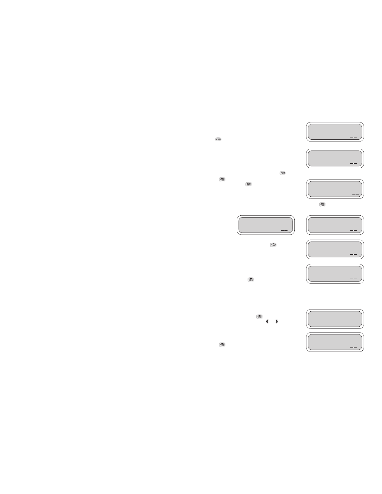
The +++Charging+++ screen appears within one minute
after the DC charger is plugged in and the handset
becomes inactive. The charging screen disappears when
the button is pressed or the charger is unplugged.
When the handset is in use, the Battery Voltage screen
appears when the handset needs to be charged. The
Battery Voltage screen will flash at lower voltage and the
word *LOW* will flash at critical voltage shortage.
This is the first screen that will appear when is pressed.
Press to continue in English or wait for Spanish to
appear and then press .
One of these screens will appear identifying the handset model. Press to continue.
This screen will appear identifying the software versions
that are installed in the handset. Press to continue.
This screen will appear with the date and time. If the
handset is being programmed for the first time it will not
display the correct time and date. Update this screen in the
next few steps, or press to continue.
SETTING UP THE HANDSET
The Setup Handset screen allows the user to program the remote with a password, date, time,
Handset ID, and Client ID numbers. This is a one-time
setup that can be updated if needed.
To enter Setup Handset press . To skip Setup Handset
and move to the next feature, press or to continue.
This screen appears with a default password. The
password can be kept or changed in the next few screens.
Press to continue.
3
screen appears when the handset needs to be charged. The Battery Voltage screen will flash at
lower voltage and *LOW* will flash at critical voltage shortage. A car charger model 30-722 can be
purchased if needed.
6. Battery Compartment Cover
To remove the battery pack, unscrew the Philips screw and remove the cover.
7. Battery Socket Outlet
Used to connect the batteries to the handset. To replace the battery, hold the battery connector and
press on the side to remove the connector. Pull out the battery and replace.
8. Socket Outlet for Software Upgrade
The handset can be upgraded to the newest software as it becomes available. The manufacturer
(DIG Corp) must perform this software upgrade.
9. Battery Compartment
Battery compartment with 3 NiMH rechargeable AAH cells battery pack (replaceable).
SETTING UP THE LEIT LINK HANDSET AND LEIT XRC CONTROLLER
IMPORTANT: In order to establish 2-way communication between the LEIT Link handset and the
LEIT XRC controllers, a simple set up process using Radio Setup in both units must be completed.
1. Settings in Radio Setup on the LEIT XRC should be changed from Local Mode to Remote Mode.
2. Controller ID addresses and Group Number addresses should be assigned to each controller
and handset in the system.
3. The radio-receiving module within the controller is automatically turned off at night to conserve
power.The start and stop times are selectable, the default is 7 AM to 5 PM.
4. The same Client Code Number must be assigned to all units, handsets and controllers. In
addition, a descriptive Controller Address can be assigned with up to 14 characters to uniquely
identify each location.
Note: No 2 handsets or controllers in the same group number can have the same ID number.
IMPORTANT: Communication between the LEIT Link and the LEIT XRC controllers is
automatically limited to daylight hours when there is sufficient light energy (un-shaded
daylight). Bright light will enable the radio to operate automatically,overriding the start/stop
times in Radio Setup.
COMMUNICATION SOFTWARE PROTOCOL:
Local Mode: The LEIT XRC controller is not listening to a signal from the LEIT Link Remote Control
Handset. (Set in controller Radio Setup.)
Remote Mode: Allows the LEIT XRC controller to scan for a signal from the LEIT Link Remote
Control Handset. (Set in controller Radio Setup.)
Client Code Number: Allows a user to have a unique identity code for their LEIT XRC controllers and
LEIT Link handset. This is a security feature, which locks out unauthorized users. This is set as a
description (AAAAA01_ZZZZZ99).All units should have the same description. (This code is set in the
handset and in the controller during Radio Setup.)
ID Address: Used as an individual address for a single controller and handset within a group of
controllers. (This ID is set in the handset and in the controller Radio Setup.)
Group Number: Allows for a group of controllers to be isolated from another group. (This number is
set in the handset and in the controller Radio Setup.) (MULTI-PRO handsets will communicate with
group 1 only.)
+++Charging+++
x.xxV
OK
Battery Voltage
*LOW*
OK
Press YES for
English Language
OK
LEIT Link™
MASTER™
OK
LEIT Link™
MULTI-PRO™
OK
SW Ver X.XX
EE Ver X.XX
OK
TUE 01/01/06
01:26 PM
OK
SETUP
HANDSET?
Password: AAA
OK
Page 5
6
COMMUNICATING WITH A LEIT XRC CONTROLLER
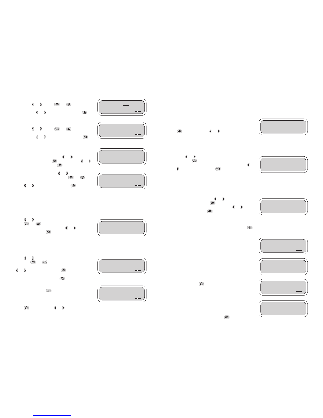
The Uplink Radio screens allow the LEIT Link handset to link to a LEIT XRC controller in just a few
steps. In going though these steps you will select the controller Group ID (LEIT Link Master only),
and the Controller ID to be used for identification purposes when linking to a LEIT XRC controller.
After linking to the LEIT XRC controller, you can review
status information and then select from a wide range of
options to communicate with the LEIT XRC controller. Press
to continue. Press or to quit or for help.
This option is available on the LEIT Link MASTER only.
The Group # Number allows the handset to link to a controller within a group of controllers, which
have the same Group #. This gives the user the flexibility to address an individual controller in a
group of controllers by location or area.
Press or to underscore one of the two numbers
then press to select a number. Repeat the steps with
the second number to select the Group #, then press or
to underscore OK. Press to confirm and continue
to the next step, selecting the Controller ID.
The Controller ID is an individual identity address that allows you to link to a single controller, which
has this ID. On first contact, the Select ID screen displays two numbers that allow for a number
from 1-99 to be entered as the controller’s identity address. In order to link to a LEIT XRC controller,
which has an ID, you must enter the same identity address into the handset.
To set a Controller ID, press or to underscore one of
the numbers, then press to select a number. Repeat
the steps with the second number. Press or to
underscore OK. Press to confirm and connect to a
LEIT XRC controller with the same ID. The handset should
be establishing a link with this LEIT XRC controller.The word Select changes to Connect while
waiting for confirmation. If communication is not established the No Response-Try Again screen
will appear with Yes highlighted as the default. Press again to initiate communication with a
LEIT controller that has the same ID.
When initial contact has been established with a controller,
the first 10 characters of the controller description will
replace the word Controller. Up to 31 most recently
accessed addresses are displayed in this way. If no
description is entered the screen will show NO_DESCRIP.
The handset power is low; the handset needs to be
charged.
The handset has established a link with a LEIT XRC
controller. Press to continue.
The controller has responded and has sent its description
(if entered). The screen indicates that a description has
been entered into the controller.The handset can be used
to modify this description, which is described later in detail
in the Uplink System section. Press to continue.
5
To set the time for the handset, underscore the appropriate
digits using or . Press or to change the
digit setting. Repeat the steps until time is set. When
finished, press or to underscore OK. Press to
continue to set the date.
To set the date for the handset, underscore the appropriate
digits using or . Press or to change the
digit setting. Repeat the steps until date is set. When
finished, press or to underscore OK. Press to
continue setting Handset ID.
The Change Password feature allows you to change the
default password (AAA) to any 3-digit combination of
letters. To change password, press or and
underscore Yes then, press to select. Press or
again to underscore OK. Press to continue.
To enter a new password press or and underscore
the first digit to be changed, then press or to
change the letter. Repeat the steps for each letter then,
press or to underscore OK. Press to
continue. When finished, write down the password so as
not to forget it.
Handset ID is used as an individual address to identify the handset if more then one handset is used
(the permissible ID is 100-199.) To give the LEIT Link handset a unique address, the Handset ID
displays three characters in which the hundred’s (1) cannot be changed.The two characters allow a
number from 0-99 to be entered as the Handset Identity address.
Press or and underscore one of the characters.
Press or to select a number. Repeat the steps
with the second number. Then press or to
underscore OK. Press to confirm and to continue to
the next step, selecting a Client ID.
The Client ID number allows a user to have a unique identity code for their field controllers and
handsets. This is a security feature, which locks out unauthorized users (the permissible ID is any
letter and number combination that follows this format: AAAAA01_ZZZZZZ99).
Press or to underscore the first of the characters
then press or to select the character. Repeat
the steps with each of the characters. When finished, press
or to underscore OK. Press to confirm the
setting. If the setting has been changed, the next step will
remind you of the change. Press to continue.
This screen let’s you know the handset is Ready for
Communication. Press to continue to the next step:
Communicating with a LEIT XRC controller using the Uplink
Radio screen.
Press to repeat. Press or to uplink Radio.
Date: 01/01/06
OK
Handset ID: 101
OK
Client ID: AAAAA01
OK
Ready for
Communication
OK
UPLINK
RADIO?
Select ID: 12
Controller:
OK
Select ID: 12
NO_DESCRIP
OK
LEITLINK
Connected
OK
1210 ACTI LEFT
ID12 Location
OK
Cont:12 voltage
*LOW*
OK
Time: 01:37 PM
OK
Group: 01
OK
Change Password?
0 Yes 0 No
OK
Enter New AAA
Password:
OK
Page 6
8
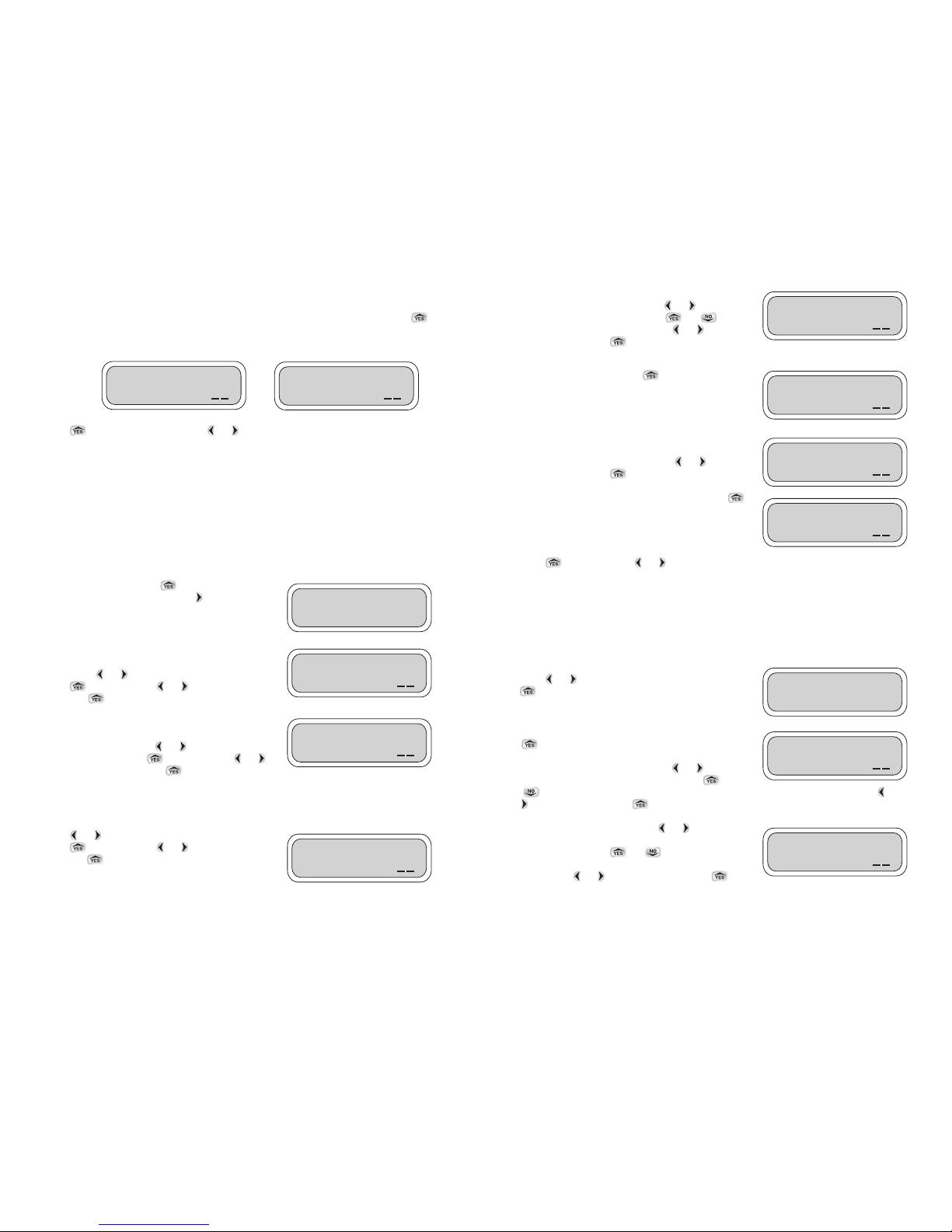
If Test has been selected, select the valve number to test in
the Test Valve number screen. Press or to
underscore the valve number. Press or to
select the valve number to test. Press or again to
underscore OK. Press to continue.
Test duration is 2 minutes, and cannot be changed.
If the valve is turned ON, press to turn the valve OFF.
Yes is the default. If desired, select Yes to continue or
select No to exit. The valve that is ON can be turned OFF,
to turn the valve OFF, select Yes. Press or to
underscore OK. Press to continue.
You can repeat the steps to turn the valve ON. Press
again to turn on the same valve or to select another valve.
Press to repeat. Press or to move to the next feature.
SETTING UP TEMPORARY SUSPENSION OF ALL IRRIGATION PROGRAMS
The Uplink Rain Stop option is used to temporarily suspend all irrigation programs. For example,
during rainy weather you can stop regularly scheduled programs from watering. The Uplink Rain
Stop feature allows you to pause irrigation from 1–99 days. At the end of the designated period,
regularly scheduled programming will resume automatically.
To skip Uplink Rain Stop and to move to the next feature,
press or to continue. To review Rain Stop press
.
If the password appears with the default (AAA), press
to continue. If the password has been changed on
the controller, enter the new controller password to
continue. To enter the password press or and
underscore the digit to be changed then press or
to select the appropriate letter. Repeat the steps for each letter.When finished, press or
to underscore OK. Press to continue.
To activate Uplink Rain Stop, press or and
underscore the number of days you wish to suspend
watering. Then, press or to highlight the
number of days you want to suspend irrigation (from 1-99
days). Press or to underscore OK. Press to
continue.
Rain Stop will cancel itself automatically at 12 AM on the last day of the Rain Stop program setting.
7
These screens show the user the controller’s actual status. In these screens you can review how
many valves the controller has, if any of the programs are active, if any valve is open, if manual is
on, if the controller is being used with the LEIT key and if any other handsets are active. Press
to review each screen and to exit. If the LEIT XRC controller has no activity, the first screen on the
right indicates that the controller is ready and available.
Press to Uplink Manual Run. Press or to move to the next feature.
SETTING UP A MANUAL RUN
The first option available on the main menu is to perform a remote Manual Run, if needed.
Manual Run is useful for checking the proper operation of stations (especially after installation), for
applying additional water as required, or repeat testing of any individual valve.
The Manual Run feature allows one to suspend a program or valve watering schedule, test a
selected valve, make a temporary program and skip any valve if needed. Note that at the
completion of Manual Run any programmed irrigation schedule reverts back to normal operation.
NOTE: A manual run can not be initiated if the key is inserted or if a manual run from another
handset is in progress. In this case the Manual Run screen will not be seen.
To review Manual Run, press . To skip Manual Run
and to move to the next feature, press to continue.
NOTE: Manual Run feature temporarily overrides any
Sensor Reading, Rain Stop, or Budgeting.
If a program or valve is running, select Yes or No to
continue (this screen will not be shown unless a valve is
open). Press or and underscore Yes or No,then
press to select. Press or again to underscore
OK. Press to continue.
If a valve is open you must select one of the options
available, such as, Suspend Program number or Stop Valve
number. To continue, press or and underscore one
of the options, then press to select. Press or
again to underscore OK. Press to continue.
This screen allows the user to select a temporary program, test a valve or exit the program. If Temp
is selected, select a run time for each valve and start Manual Run. After manual run start, you can
skip to the next valve at any time.
Press or and underscore one of the options, then
press to select. Press or again to underscore
OK. Press to continue.
UPLINK
MANUAL RUN?
Stop Pro/valve
0Yes 0No
OK
0 Suspend Prog:___
0 Stop valve:___
OK
Run Prog: 0 None
0Test 0Temp
OK
Test Valve:01
Turn ON?
OK
UPLINK
RAIN STOP?
Password: AAA
OK
Stop for 00 Days
OK
Controller: 01-10
Valves Closed
OK
Controller:12 is
BUSY–LEITKEY
OK
Valve:01
ON
OK
Tu rn
OFF 0Yes 0No
OK
Valve:01
Off
OK
Page 7
10
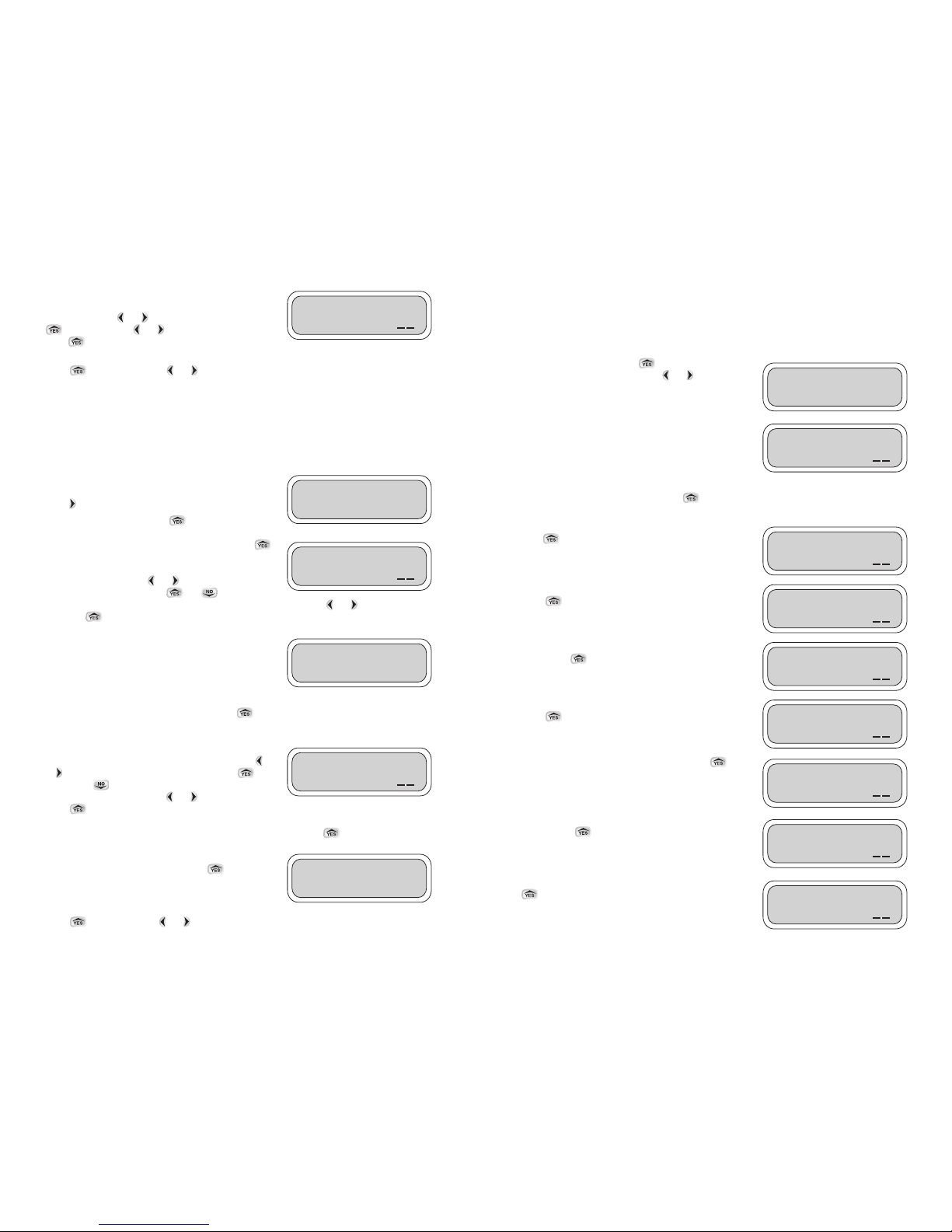
REVIEW A CONTROLLER STATUS
This feature allows you to review the current controller status for the time, date, sensor activation,
active program or valve, manual run, rain stop progress, month off if any, short or open circuit in
valve wiring or valve open. It also provides information on the controller’s power range and
availability for communication.
To review Check Status press . To skip Check Status
and move to the next feature, press or to continue.
After selecting Controller ID address, the handset will
establish a link with a LEIT controller that has this same
address. While the word Connect is blinking, wait for a
confirmation. After communication is established, the
following information screens will provide a status report
on the controller. If communication is not established the No Response-Try Again screen will appear
with Yes highlighted as the default. Press again to re-initiate communication with a LEIT
controller that has the same ID.
This screen appears if the controller is low on power.
Press to continue.
This screen appears if any program or valve is active.
Press to continue.
This screen appears if any program or group of valves is
active. Press to continue.
This screen appears if the Manual Run is in progress.
Press to continue.
This screen appears if Rain Stop is active. Press to
continue.
This screen appears if irrigation has stopped for a full
month. Press to continue.
This screen appears if the valve wiring is open. Press
to continue.
Cont:12 voltage
*LOW*
OK
Prog:X Active
Valve xx Open
OK
Prog:X Active
GRPxx:yy Open
OK
Manrun Active
Valve:XX Open
OK
Rainstop Active
xx More Days
OK
Irrigation Stop
for Month XXX
OK
UPLINK
STATUS?
Connect ID: 12
Controller:
OK
Station xx O/C
Wiring Fault
OK
9
If Rain Stop is active you can manually cancel the Rain
Stop anytime by re-entering the Uplink Rain Stop screen.
Once there, press or to underscore Yes,then press
to select. Press or again to underscore OK.
Press to continue.This will bring you back to the
Uplink Rain Stop screen.
Press to repeat, or press or to move to the next feature.
SETTING UP A MONTHLY BUDGET FOR ALL PROGRAMS
Instead of changing the duration for each program, you can use the Uplink Monthly Budget feature
to increase or decrease the amount of water used during seasonally dry or wet periods on a
monthly basis. Budget adjustments can range from 10-200% in 10% increments. The LEIT
controller will automatically adjust the previously programmed duration for each program according
to the specified budget.
To skip Uplink Budget and to move to the next feature,
press to continue.
To enter Monthly Budget, press to continue.
If the password appears with the default (AAA), press
to continue. If the password has been changed on the
controller, enter the new controller password to continue. To
enter the password press or and underscore the
digit to be changed then press or to select the
appropriate letter. Repeat the steps for each letter.When finished, press or to underscore
OK. Press to continue.
After selecting Controller ID the handset will establish a
link with a LEIT controller.While the word Connect is
blinking, wait for a confirmation. After communication is
established, the following information screens will provide
you with 12 months of budget information. You can adjust
any month as needed. If communication is not established the No Response-Try Again screen will
appear with Yes highlighted as the default. Press again to re-initiate communication with a
LEIT controller that has the same ID.
Budget information for the previous 12 months will appear
with January first and 100% as the default. Press the
or to underscore the percentage digits. Press to
increase or to decrease the percentage (in
increments of 10%). Press the or to underscore OK.
Press to advance to the next month and repeat the steps for each of the months as needed. If
any of the months have been changed, the new information will need to be uploaded by
establishing a link with the LEIT controller with same ID address. Press to continue.
Communication has been established and the newly
revised setting has been accepted. Press to continue.
Press to repeat. Press or to move to the next feature.
Cancel Rainstop?
0Yes 0No
OK
Connect ID: 12
Controller:
JAN 100%
Budget:
OK
Revised
BUDGET
UPLINK
BUDGET?
Password: AAA
OK
Page 8
12
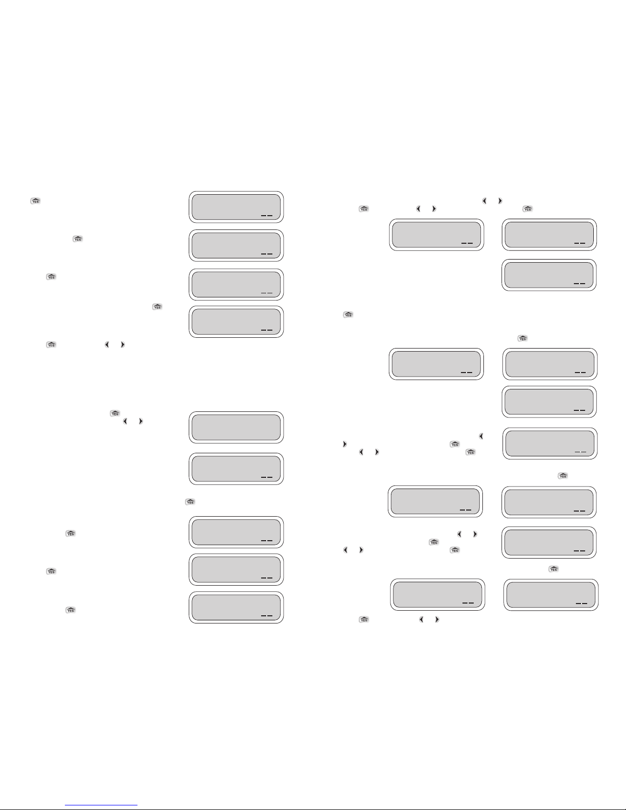
These screens review information on specific month. To review this information, select Yes for the
selected month or No to skip to the next month. Press or and underscore Yes or No,then
press to select. Press or again to underscore OK. Press to continue.
If a specific month was selected in the previous screen, the
handset will try to establish a link with the LEIT controller
with the same Controller ID to retrieve this information.
While the word Connect is blinking, wait for a confirmation.
After communication is established, the following screens
will provide you the information on the specific month you selected. If communication is not
established the No Response-Try Again screen will appear with Yes highlighted as the default.Press
again to re-initiate communication with a LEIT controller that has the same ID.
These example screens provide the monthly watering totals as requested in the previous step. This
information is available by month for the previous 11 months. Press to continue.
To review a total usage report for each year, select Yes for
the selected year or No to skip to the last year. Press or
and underscore Yes or No, then press to select.
Press or again to underscore OK. Press to
continue.
These two screens show current year usage for a valve and for all the valves. Press to
continue.
To review information on total usage for last year, select
Yes for the selected year or No to exit. Press or and
underscore Yes or No, then press to select. Press
or again to underscore OK. Press to
continue.
These two screens show last year usage for a valve and for all the valves. Press to continue.
Press to repeat. Press or to move to the next feature.
Valve1 Use NOV
Month: 9.55
OK
NOV05 TOTAL This
Month: 22:34
OK
OCT 05 MAN This
Month: 2:30
OK
YR:06 TOT/Valve?
0Yes 0No
OK
Total Use This
Yr:06: 9010:86
OK
Valve01 Use This
YR:06: 1682:34
OK
YR:05 TOT/Valve?
0Yes 0No
OK
Valve01 Use last
YR:05: 1040:66
OK
Total Use Last
YR:05: 3010:86
OK
NOV05 Tot/Valve?
0Yes 0No
OK
DEC05 Tot/Valve?
0Yes 0No
OK
Connect ID: 12
Controller:
OK
11
This screen appears if there is a short in the wiring. Press
to continue.
This screen appears with time and the date of the
controller. Press to continue.
This screen appears when the sensor allows watering.
Press to continue.
This screen appears if no sensor is used. Press to
continue.
Press to repeat. Press or to move to the next feature.
REVIEW THE CONTROLLER HISTORY REPORTS
This feature allows you to review the controller History Reports for total watering time for each
valve with overall total and manual run total. This information is available for the current month and
the previous 11 months. Also available on the report is the total usage and overall usage per valve
for the current and previous year.
To review History Report press . To skip History Report
and move to the next feature, press or to continue.
After selecting Controller ID, the handset will establish a
link with a LEIT controller that has this same identity
address. While the word Connect is blinking, wait for a
confirmation. After communication is established, the
following information screens would provide you with a
history report on the controller. If communication is not established the No Response-Try Again
screen will appear with Yes highlighted as the default. Press again to initiate communication
with a LEIT controller that has the same ID.
This screen shows total time usage for each valve this
month. Press to continue.
This screen shows total time usage for the current month.
Press to continue.
This screen shows total manual usage for the current
month. Press to continue.
FRI 1/26/05
01:37 PM
OK
UPLINK
HISTORY?
Connect ID: 12
Controller:
OK
Valve01 Use This
Month: 2:34
OK
JAN06 TOTAL This
Month: 12:34
OK
JAN06 MAN This
Month: 0:30
OK
Station xx S/C
Wiring Fault
OK
Sensor is
Unused
OK
Sensor allows
Watering
OK
Page 9
14
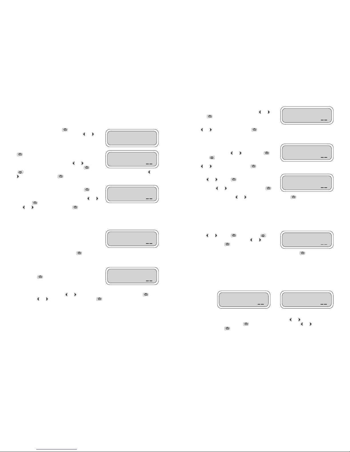
To select or change the day of the week, underscore the
appropriate box under the preferred day using or
and press to confirm. The selected days will show a
checkmark instead of the empty boxes. Repeat the steps
again to select other days. When all tasks are completed,
press or to underscore OK. Press to confirm and continue to the Start Time screen.
SETTING START TIME
From this screen select up to 3 start times a day (including
AM or PM). To select the first start time underscore the
appropriate digit using the or . Then, press to
increase or to decrease the value of the appropriate
digit. Repeat the steps again for each digit. When finished,
press or to underscore OK. Press to continue and set the second start time.
If a second start time is needed, underscore and highlight
Yes using or . Press to select. Repeat the steps
from the first start time to set the second start time. When
complete press or to underscore OK. Press to
continue to third start time set up. For a third start time
repeat the steps again. Press or to underscore OK and press to continue. You can
later
cancel any of the additional start times simply by selecting No instead of Yes within each start time.
SETTING UP DURATION
When scheduling or changing a duration time for each valve, note that a runtime from 1 minute to 5
hours and 59 minutes in 1-minute increments can be set. If needed any number of valves can
operate at the same time (if hydraulic limitations are not exceeded).
To set the valve duration, underscore the appropriate digits
using the or . Press to increase or to
decrease the hour or minute digit. Press or and
underscore OK. Press to continue to the second
valve. Follow the same procedure as before for the second
and remaining valves. To skip a valve, leave the duration on zero and press to continue. Note
that the duration selected for each valve will be repeated with each of the three start times (if used).
GROUPING VALVES TO OPERATE AT THE SAME TIME
Use the Valve Runtime screen to program more then one valve to open or close together in a group
as opposed to the normal operation mode. To select valves, which are to be grouped and operate at
the same time, set the duration for the first valve and add the letter G to the rest of the valves in this
group. The first valve and the remaining valves are linked together.
Example: Linking Valve #2 to Valve #1
Set a time for Valve #1.While in the Valve #2 Runtime screen, press or and underscore the
icon left of the hour position. Press and the letter G will appear. Press or and
underscore OK. Press to confirm.
The letter G signifies that Valve #2 is now grouped to Valve #1,with Valve #1 being the group leader.
The watering time for this group leader will be applied to all consecutive valves that show the letter
G in the Valve Runtime screen.
Valve 01 0:02
Start:
OK
Valve 2 G0:00
Runtime:
OK
Valve 1 0:12
Runtime:
OK
Water MTWTHSS
Days: ✔ ✔ ✔
OK
2nd Start time?
0Yes 0No
OK
1st 02:00AM
Start:
OK
13
REVIEW OR CHANGE THE PROGRAMMING SCHEDULE
This feature allows you to review, change or set a schedule with up to four separate programs for
each station, each with up to three individual start times per day.It will also allow you to group
stations together (if hydraulic limitations are not exceeded).
To enter Uplink Schedule press . To skip Uplink
Schedule and move to the next feature, press or to
continue.
If the password appears with the default (AAA), press
to continue. If the password has been changed on
the controller, enter the new controller password to
continue. To enter the password press or and
underscore the digit to be changed then press or
to select the appropriate letter. Repeat the steps for each letter.When finished, press or
to underscore OK. Press to continue.
This screen displays a choice of 4 programs. The first
active program is highlighted by default. Press to
continue programming Program #01. To select another
program, underscore the program number using or
and press to highlight the program number. Press
the or to underscore OK. Press to confirm and to continue to the next screen.
Note: Additional programs will not run unless you have activated the program number. If a
program is selected which is not active the opportunity is provided at this point to activate it.
See Uplink Setup System page 17.
Next, the handset will try to establish a link with a LEIT
controller.While the word Connect is blinking, wait for a
conformation. If communication is established, the
Password screen appears. If communication is not
established the No Response-Try Again screen will appear
with Yes highlighted as the default. Press again to re-initiate communication with a LEIT
controller that has the same ID.
If communication is not established the No Response-Try
Again screen will appear with Yes highlighted as the
default. Press again to re-initiate communication
with a LEIT controller that has the same ID.
If communication is established, the following screen provides watering frequency options. To
select the preferred option, press or and underscore one of the 4 options. Press to
select. Press or again to underscore OK. Press to confirm and continue to the next
step.
If you select MTWTFSS, you’ll get the next screen selecting the day of the week:
WATERING CALENDAR OPTION
Every: operates stations from once a day to once every 39 days
Even: every even-numbered day
Odd: every odd-numbered day
MTWTFSS: select specific day(s) of the week
Program Number:
01 02 03 04
OK
Connect ID: 09
Controller:
OK
0Every . . 0Even
0MTWTFSS 0Odd
OK
UPLINK
SCHEDULE?
Password: AAA
OK
Page 10
16
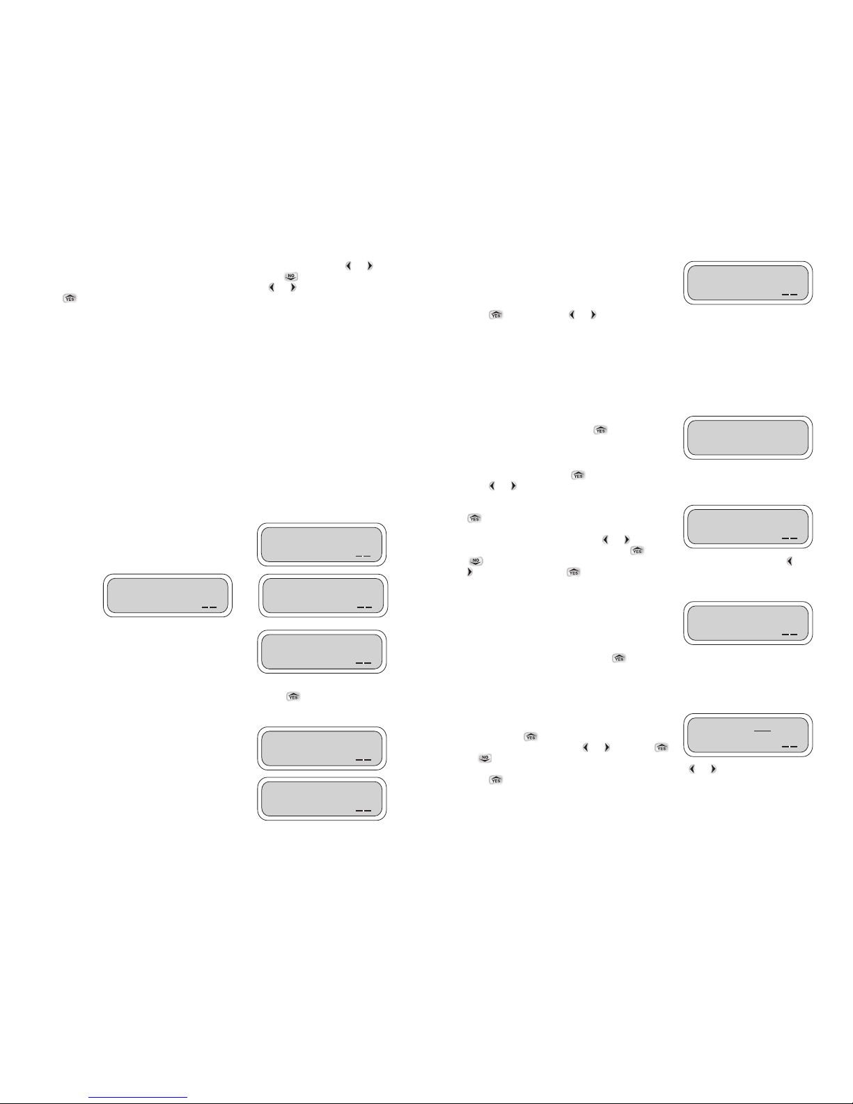
This screen provides information on the next irrigation
schedule.
Press to repeat. Press or to move to the next feature.
SETTING THE CONTROLLER SYSTEM
This Uplink System menu allows you to set the current controller date and time, activate or deactivate programs, activate or deactivate budgeting, enter or change master valve or pump settings
and activate monthly irrigation suspension. In this menu you may also set or change controller radio
on/off times, assign an address or description to the controller, activate a sensor, assign a sensor to
one, all valves or a MV/P and change the passwords. After any changes to the system have been
made, a confirmation will appear on the display.
To enter Uplink Setup System press .
To enter Uplink System press to skip Uplink System and move to the next feature,
press or and continue.
If the password appears with the default (AAA), press
to continue. If the password has been changed on
the controller, enter the new controller password to
continue. To enter the password press or and
underscore the digit to be changed then press or
to select the appropriate letter. Repeat the steps for each letter.When finished, press or
to underscore OK. Press to continue.
Next, the handset will try to establish a link with a LEIT
controller.While the word Connect is blinking, wait for a
conformation. If communication is established, the
Password screen appears. If communication is not
established the No Response-Try Again screen will appear
with Yes highlighted as the default. Press again to re-initiate communication with a LEIT
controller that has the same ID.
SETTING THE TIME
In this screen the time is displayed. You may review or
change any of the information if the time displayed is
incorrect. Press to continue. To set the time,
underscore the hour digits using or and press
or to change the setting. Repeat the steps for
changing the minute digit and AM/PM and when finished press or again to underscore OK.
Press to continue.
Password: AAA
OK
Time: 01:37 PM
OK
Prog1 Strt2 next
Sched 12:50pm
OK
UPLINK
SETUP SYSTEM?
Connect ID: 09
Controller:
OK
15
To remove the letter G from a valve in the group: In the Valve Runtime screen press the or to
underscore the letter G icon located to left of the hour position. Press and the letter G will
disappear. Repeat with the other valves as needed. To exit press or to underscore OK.
Press to continue.
The following examples are of groups (G or 0 can be set for intermediate valves in a group)
Valve #1 set for 0:20 minutes
Valve #2 set for G0:00 or 0:00
Valve #3 set for G0:00 or 0:00
Valve #4 set for G0:00
Valves #1-4 grouped with runtime of 20 minutes
Valve #5 set for 0:10 minutes
Valve #5 with runtime of 10 minutes
Valve #6 set for 0:15 minutes
Valve #6 with runtime of 15 minutes
Valve #7 set for 0:25 minutes
Valve #8 set for G0:00 or 0:00
Valve #9 set for G0:00 or 0:00
Valve #10 set for G0:00
Valves #7-10 grouped with runtime of 25 minutes
It is possible to set more than one group.
NOTE: When selecting or changing a grouped program, cycle through all the valves on the
program to save the changes before you exit.
If a program is uploaded or changed and an error was
made, you will see the errors in one or more of these 3
screens. If no errors were made, none of these 3 screens
will appear.
If any changes have been made, the handset will establish
a link with a LEIT controller, which has the same Controller
ID number. While the word Connect is blinking, wait for a
confirmation. After communication is established, the new
settings (if revised) are uploaded. The following screens
will confirm the changes on the controller. If communication is not established the No ResponseTry Again screen will appear with Yes highlighted as the default.Press again to re-initiate
communication with a LEIT controller that has the same ID.
Program Number #1 is the default program. This screen
confirms that controller ID #09 has selected an additional
program.
This screen confirms that controller ID #09 has accepted a
schedule, run time or duration changes in the program.
Prog1 Time More
than 24 Hours
OK
Prog1 Start2
Before Start1
OK
Prog1 Overlaps
Start 2
OK
Connect ID: 12
Controller:
OK
Changed Ctrl:09
Active Progs.
OK
Changed Ctrl:09
Prog.1 Schedule
OK
Page 11
18
This screen allows a complete shut off of the system for
any month of the year. By default all months are active. To
activate any month select or and underscore Yes,
then press to select. Press or again to
underscore OK. Press to continue.
In this screen, the 12 months can be activated or
deactivated. By default all the months are active
(checked). To enable the controller to activate or cancel
any month of the year, simply add or remove the
checkmark. To deactivate any month, press or to
underscore the appropriate month and press to deactivate (remove the checkmark). Repeat
the steps to activate or deactivate additional months. Press or again to underscore OK.
Press to continue.
This screen activates the solenoid for a test of shorts or open wires. In this screen, the short and
open valve test is deactivated by default (not checked). To enable the controller to activate one or
both of the two Short or Open features, simply add or remove the checkmark.
Press or to underscore the appropriate box and
press to activate (checked). Repeat the steps to
activate or deactivate the other option. Press or
again to underscore OK. Press to continue.
Note: The test of the valve takes place when the valve is operated. Fault status will appear in
Check Status menu.
ACTIVATING MV/P
This screen has two options for each valve. All valves in
budget are activated by default and MV/P is deactivated by
default.
Option One MV/P: if checked, the valve number will
operate with master valve or pump.
Option Two Budget: is checked by default, the valve number is affected by the monthly budget
setting (default is 100%).
To enable the controller to use any or both of the two features, simply add or remove the
checkmark from each valve. Press or to checkmark the appropriate box. Press to
activate (checkmark) or deactivate (remove the checkmark). Repeat the steps to activate or
deactivate the other option. Press or again to underscore OK. Press to continue.
ACTIVATING SENSORS
The Sensor In Use feature indicates whether or not a
sensor is activated and in use: if sensor is installed, select
Yes.
To enable the controller to use a sensor, the first step is to
indicate that a sensor is being used. Press or and
underscore Yes or No, then press to select. Press
or again to underscore OK. Press to continue.
This screen, Sensor Location, indicates the location of the sensor. If MV/P or other is selected, this is
the location in which the sensor is connected via the SKIT 8821-4 adapter.
Active CCT Test
0Short 0Open
OK
Valve01 Options:
0MV/P ✔Budget
OK
Sensor Location:
0 MV/P 0Other
OK
Sensor In Use?
0 Yes 0 No
OK
Active JFMAMJ
Months: ✔✔✔✔✔
OK
Turn Month OFF?
0 Yes 0 No
OK
17
SETTING DATE
To set the date, underscore the appropriate digits using
or and press or to change the setting.
Repeat the steps as needed for changing the calendar and
when finished press or again to underscore OK.
Press to continue.
SETTING THE RADIO OPERATION
Radio Setup available only on model XRC Controllers.
In these screens the handset allows you to limit the controller radio operation time. You will need to
limit the use of the radio controller to daylight hours to prevent power drainage of the controller. Our
suggestion is 8 AM-5 PM. This will allow the controller to operate within the window between early
morning and late afternoon. The LEIT XRC requires greater energy for radio communication than
is used for operation of the controller alone. In order to retain sufficient energy to maintain valve
control the radio on the controllers will automatically turn off in low light conditions.
To set the time, underscore the hour digits using or and press or to change the
setting. Repeat the steps for changing the minute digit and AM/PM. When complete press or
again to underscore OK. Press to continue.
SETTING LOCATION ADDRESS
For your convenience, 14 characters are available to set up location addresses, or any other
descriptive text, to remind you of the controller location (the text available is A-Z, 0-9 and _ ).
When setting the address, OK should be blinking.
Underscore the first digit using or and press
or to select a letter or number. Press or and
the next digit will blink. Repeat the steps for changing
each of the digits and when finished press or to
underscore OK (this is the only screen that OK is blinking). Press to continue.
ACTIVATING PROGRAMS
Note: Scheduled programs will not run unless the appropriate program number is activated
and a checkmark appears in the Active Program box.
In this screen, up to 4-programs can be activated or
deactivated. Program #01 is active (checked) by default.
To enable the controller to activate or cancel any of the
stored programs simply add or remove the checkmark.
Press or to underscore the program number
press to activate (checked). Repeat the steps to activate or deactivate additional programs as
needed. Press or again to underscore OK. Press to continue.
Date: 01/25/05
OK
Radio: 05:00pm
Off
OK
Radio: 07:00am
On
OK
NO_DESCRIPTION
ID09 Location
OK
Active 1234
Progs: ✔ ■■ ■■ ■■
OK
Page 12

20
If a link is established with a LEIT controller the quality of the radio signal and the controller power
strength can be checked.
Rx = Receive signal strength at controller from handset
with a minimum of 0 and maximum 3.
Tx = Transfer signal strength at handset from controller
with a minimum of 0 and maximum 3.
2.13 V = Controller voltage where 2.13 indicates that the controller is fully charged.
Press to repeat. Press or to move to the next feature.
Rx2Tx2 2.13V x 5
Test? 0Yes 0No
OK
19
To select sensor location, press or and underscore MV/P or other, then press to select.
Press or again to underscore OK. Press to continue. If other was selected, in the next
screen specify which station number the sensor(s) is/are governed by.
NOTE: If MV/P is selected on the screen, sensor must connect to the master valve wire or
terminal. If other is selected, the sensor must be connected to one of the station's numbered
terminals.
This screen, Sensor Governs, allows you to designate,
which of the installed valves will be governed by the
sensor.To designate the valves that the sensor will control,
press or and underscore the valve numbers to be
governed by the sensor, then press to select. Press
or again to underscore OK. Press to continue.
NOTE: If an installed switch type sensor is triggered, any valve that is check marked and is
currently ON will complete its programmed run time. All further valve operations will be
prevented until the sensor deactivates and allows watering again.
The handset is trying to establish a link with a LEIT
controller.While the word Controller is blinking, wait for a
confirmation. If communication is established, the
following screens will confirm the changes. If
communication is not established the No Response-Try
Again screen will appear with Yes highlighted as the default. Press again to re-initiate
communication with a LEIT controller that has the same ID, which uploads the new setting (if
revised).
If communication is established and only one screen has
changed, only one of these screens will show. If any other
changes have been made, all the changes will show in the
following screens. Press to review the changes and
to exit.
Press to repeat. Press or to move to the next feature.
UPLINK RADIO STATUS
The Uplink Radio Status is used for testing the range between the remote control handset and the
controller.The screen also provides the voltage information of the controller.The Rx and Tx figures
give an approximate indication of radio signal strength received at the controller (Rx) and handset
(Tx). The quality of the signal at that range is identified with a number between 0-3, with 3 being
the best, strongest signal. The V signal is an indication of the voltage level at the controller.The fully
charged controller will show 2.13 V on the display.
To enter Uplink Setup System press . To skip Uplink
Radio Status and move to the next feature press or
to continue.
The word Test will flash while attempting to establish a link
with a LEIT controller. If communication is not established
the No Response-Try Again screen will appear with Yes
highlighted as the default. Press again to re-initiate
communication with a LEIT controller that has the same
controller ID.
Sensor 01 02
Governs: 03 04
OK
Connect ID: 09
Controller:
OK
Changed Ctrl:09
Time/Date
OK
UPLINK
RADIO STATUS?
Rx Tx V x5
Test? 0Yes 0No
OK
Page 13

22
6. Make sure that the water pressure is not too high (over 150 PSI). Use a pressure regulator if
necessary.
PROGRAMMING PROBLEMS:
The valves will come on using the “Manual Run” feature but will not water automatically.
Check the following:
1. The Rain Stop is active. To reactivate the program schedule, go into the Main Menu-Rain
Stop/Restart and cancel the Rain Stop (see Rain Stop, page 8-9).
2. No programming schedules have been entered yet. Go into Main Menu Setup Schedule and
enter a program (see Programming Schedule, page 13-15).
3. You programmed the controller,but did not ACTIVATE the programs. Go into Main Menu Setup
System and activate the desired programs (see Activating Programs, page 17).
4. The programmed runtime of the stations is set to “0” duration. Go into Main Menu Setup
Schedule and alter runtime (see Selecting a Watering Duration, page 14).
5. You are not using a sensor,but you programmed the system for sensor operation. Go into
Main Menu and then Uplink System to check that sensors are unused (see programming,
page 18).
6. A sensor is hooked up to the system and is in a state that inhibits watering.
7. If some valves will not operate in a manual run, enter Uplink System and set the Open
checkmark in the Active CCT test screen. Then repeat the manual run and then check the
status. If there is an open circuit (wire break) it will be reported. Repeat with the short
checkmark set, to look for short circuits (wires touching).
8. If the valves operate correctly in a manual run but not in a scheduled program check that the
following settings are correct:
• Active Programs screen.
• Sensor – Sensor in Use, Sensor Location and Sensor Governs screens.
• Month stop – Turn Month off and Month Selection screens
• Schedule start times, runtimes per program set correctly
9. If a program runs but starts unexpectedly check the schedule settings. If a new program starts
before the old program has completed it will be stacked to commence later.The handset gives
warnings if runtimes and starts overlap but the LEIT X or XRC controller does not.
10. Make sure there is enough time between the programs and/or start times to meet your
watering time in budget (up to 200% possible) (see Monthly Budgets, page 9).
11. The password has been changed or forgotten: Please call DIG Customer Service with the
Serial Number of your controller.
GROUPING
Considerations when setting up and making changes to grouped programs:
1. If a valve that was grouped is reset to 0:00, the valve will be skipped.
2. If the lead valve of a group is set to 0:00, the next valve must be given a run time to lead the
group. (If not, the orphaned group will attach to the preceding valve.)
3. If Valve #1 is a group leader and is set to 0:00, since there is no preceding valve, the group
would remain orphaned. A default run time of 0:01 is returned to Valve #1 to prevent this
occurrence.
If the provided solutions have not solved your problems, please call DIG 800-322-9146 for
technical support.
Please note that tampering with the controller,or even attempting to take it apart, will VOID any
warranty your product might be eligible for.
21
SERVICE CALL (INSTALLATION TROUBLESHOOTING)
CHECK THE LEIT CONTROLLER AND HANDSET
1. The LEIT XRC controller functions exactly the same as the LEIT X and LEIT XR controller except
for the addition of radio setup. The handset and XRC radios MUST be set up prior to operation
with Client Code, ID and Group address using the key for the XRC.
2. The XRC controller must be situated in a position of adequate light. The radio cannot maintain
proper functionality in a shaded position such as adjacent to a wall, unless it is on the “sunny”
side of the wall. If light levels drop too low the radio will turn itself off to guarantee correct
controller operation. When the radio is off, less power is used as the controller is charging.
The radio's internal circuitry will turn itself on again when sufficient light has charged the
controller to the appropriate power level. At low light levels the radio will periodically turn on
and off. For best results schedule Time on as late as possible and Time off as early as possible
in UPLINK SYSTEM.
3. The radio will function better if it is located at a higher elevation. If there is a choice do not
situate it in a hollow.
4. To communicate, the controllers and handsets MUST have the same Client Code. This is the
user's unique identification code, which prevents interference from other users in the area.
5. For LEIT Link Multi-Pro handsets, only one group, is permissible therefore all controllers must
be set to group 1 (default).
6. For LEIT Link Master handsets, the handset can communicate with controllers, which have
been arranged in functional groups and setup accordingly.
7. If two controllers in the same group are set to the same ID, communication may be disrupted
if both controllers are in range of the handset. The same occurs if two handsets are set to the
same ID and are in use at the same time. All controllers and handsets in the same group must
have a unique ID.
8. The handset needs to be kept in a charged state. After 500 – 1000 charge cycles the internal
batteries may need replacement.
9. To verify that the controller is operating correctly, insert the LEIT key and scroll to Check
Status mode. Verify if the controller accumulated the time correctly for past and current
month.
TROUBLESHOOTING YOUR CONTROLLER
ELECTRICAL PROBLEMS:
With the LEIT Key plugged into the controller,if after 2 minutes there is no visible display check
the following:
1. Check the battery in the LEIT Key and replace if necessary.
2. Make sure the LEIT Key is plugged in all the way.
Some or all valves fail to operate when using “Manual Run”. (Systems NOT USING a master
Valve/Pump)
Check the following:
1. Make sure that the red (hot) wires of the actuators are spliced to the hot field wires leading to
the controller.
2. Make sure all the white (common) wires of the actuators are connected to the common field
wire leading back to the controller.
3. Insert all field wires (with 3/10” of insulation stripped from the end of the wires) firmly into the
controller connector and tighten the appropriate screws so as to ensure good connection.
4. Make sure that the wires are corrosion free, the joints are tight and made waterproof.
5. Make sure that there is adequate water pressure.
 Loading...