

Page 1
Website: E
http://www.digcorp.com
e-mail: [email protected]
022208 DIG CORP 26-061
Printed in the USA
1210 Activity Drive
Vista, CA 92081-8810, USA
8. Warranty
DIG CORPORATION warrants these products to be free from defects in material and workmanship for
a period of three years from date of purchase. This warranty does not cover damage resulting from
accident, misuse, neglect, modification or improper installation. This warranty shall extend only to
the original purchaser of the product for use by the purchaser. This warranty shall not cover batteries
or any malfunction of the product due to battery failure. The obligation of DIG CORPORATION under
this warranty is limited to repairing or replacing at its factory this product which shall be returned to
the factory within three years after the original purchase and which on examination is found to
contain defects in material and workmanship.
DIG CORPORATION SHALL IN NO EVENT BE LIABLE FOR ANY INCIDENTAL OR CONSEQUENTIAL
DAMAGES OF ANY KIND; THE SOLE OBLIGATION OF DIG BEING LIMITED TO REPAIR OR
REPLACEMENT OF DEFECTIVE PRODUCTS. SOME STATES DO NOT ALLOW THE EXCLUSION OR
LIMITATION OF INCIDENTAL OR CONSEQUENTIAL DAMAGES, SO THE ABOVE LIMITATION OR
EXCLUSION MAY NOT APPLY TO YOU.
Unattended use for prolonged periods without inspection to verify proper operation is beyond the
intended use of this product, and any damage resulting from such use shall not be the responsibility
of DIG CORPORATION. There are no warranties which extend beyond the description on the face
hereof. In the case of purchase of the product for use other than, for irrigation purposes, DIG
CORPORATION hereby disclaims any implied warranties including any warranties of merchantability
and fitness for a particular purpose. In the case of the purchase of the product for personal, family or
household purposes, DIG CORPORATION disclaims any such warranties to the extent permitted by
law. To the extent that any such disclaimer or implied warranties shall be ineffectual, then any
implied warranties shall be limited in duration to a period of three years from the date of the original
purchase for use by the purchaser. Some states do not allow limitation on how long an implied
warranty lasts, so the above limitation may not apply to you.
In order to obtain performance under this warranty, the unit must be returned to the factory, along
with proof of purchase indicating original date of purchase, shipping prepaid, addressed as follows:
DIG CORPORATION, 1210 Activity Drive, Vista, CA 92081-8510. Repaired or replaced units will be
shipped prepaid to the name and address supplied with the unit returned under warranty. Allow four
weeks for repairs and shipping time. Repair of damaged units not otherwise within warranty may be
refused or done at a reasonable cost or charge at the option of DIG CORPORATION.
This warranty gives you specific legal rights, and you may also have other rights which vary from
state to state.
1
2-Way Radio Controller
Operating Instructions
English
Page 2
Table of Contents
A. Introduction …………………………………………………………………3
B. About the LEIT-2 system ………………………………………………………3
C. Technical assistance …………………………………………………………4
D. Copyright and compliance ……………………………………………………5
E. Features………………………………………………………………………6
1. System ………………………………………………………………7-10
1.1 Parts identification ……………………………………………………7
1.2 System components …………………………………………………7-8
1.3 Tools and supply requirements …………………………………………9
1.4 Quick installation setup and operation review…………………………9-10
2. Installation ……………………………………………………………10-17
2.1 Solenoid and valve installation ……………………………………10-11
2.2 Controller installation …………………………………………………12
A. Valve box mounting dome ………………………………………12-13
B. Mounting column ………………………………………………13-16
C. Valve mounting ……………………………………………………16
2.3 Maximum wire run ……………………………………………………17
3. Initial communication between handset and controller ………………………17
3.1 Initiating communication for the first time………………………………17
3.2 Initial connection to the LEIT-2 using the LEIT RC2 handset …………17-18
4. Using a sensor ……………………………………………………………19
4.1 Sensor installation ……………………………………………………19
4.2 Compatible sensors …………………………………………………19
5. Troubleshooting …………………………………………………………19
5.1 Troubleshooting controller ……………………………………………19
5.2 Troubleshooting solenoids ……………………………………………20
5.3 Troubleshooting hydraulic valves ………………………………………21
5.4 Troubleshooting control valves…………………………………………21
6. Record chart………………………………………………………………22
7. Programming Quick Reference Chart ………………………………………23
7. Warranty …………………………………………………………………24
2
A. Introduction
Thank you for purchasing DIG’s LEIT-2 controller, which operates as part of the
LEIT-2 system. This manual describes how to get the LEIT-2 controller up and
running quickly. After reading this manual and having been familiarized with
the basic functionality of the controller, the manual can be used as a reference
for less common tasks in the future.
B. About the LEIT-2 System
The LEIT-2 ambient light (solar) powered irrigation controller is an advanced
wireless device that is programmed using the LEIT RC2 remote handset. The
LEIT-2 controller is comprised of a photovoltaic module (PVM panel), 2 pairs of
18” (45 cm) station wires (labeled #V1 and #V2) used to connect the controller
with up to two S-305DC solenoids, plus a pair of yellow wires for sensor
connection. The LEIT-2 has an ultra-compact photovoltaic module that
harnesses light energy to generate electricity that is stored and used to power
the controller day and night in any kind of weather. The LEIT-2 controller is
operated using the LEIT RC2 remote control handset, which has an operating
range via a 2-way radio of up to 350 ft (100 m) line of sight.
The LEIT-2 controller requires daily exposure to light levels at a minimum of
3000 lux, which is equivalent to daylight around 7-8 AM on a cloudy day. On
very cloudy days the controller requires more time to charge up and to operate
with the radio.
IMPORTANT:
Communication between the LEIT RC2 handset and the LEIT-2
controllers are automatically limited to daylight hours when there is sufficient
light energy. Longer bright light days will enable the radio to operate
automatically over longer parts of the day, including through the night.
3
Page 3
D. Copyright and Compliance
Copyright 2006-2007 DIG Corporation. All rights reserved. LEIT-2 and LEIT RC2
are each trademarks of DIG Corporation. Patent pending
FCC, EC, Canada and Australia compliance
To comply with FCC RF exposure compliance requirements, the antenna used for this
transmitter is installed to provide a separation distance of at least 8 inches (20 cm) from all
persons (not including hands, wrist, feet and ankles) and must not be co-located or operating
in conjunction with any other antenna or transmitter.
This device is required to comply with FCC RF exposure requirements for mobile and fixed
transmitting devices. This model transceiver generates and uses radio frequency energy. If not
installed and used in accordance with the manufacturer’s instructions, it may cause
interference to radio and television reception.
CONTROLLER FCC ID: UJV-LEIT01 IC: 6694A-LEIT01
HANDSET FCC ID: UJV-LEIT02 IC: 6694A-LEIT02
This equipment has been tested and found to comply with the limits for a Class B digital
device, pursuant to part 15 of the FCC Rules. These limits are designed to provide reasonable
protection against harmful interference in a residential installation. This equipment generates,
uses and can radiate radio frequency energy. If not installed and used in accordance with the
instructions, the remote may cause harmful interference to radio communications. However,
there is no guarantee that interference will not occur in a particular installation. If this
equipment does cause harmful interference to radio or television reception, which can be
determined by turning the equipment off and on, the user is encouraged to try to correct the
interference by one or more of the following measures:
• Reorient or relocate the receiving antenna.
• Increase the separation between the equipment and receiver.
• Connect the equipment into an outlet on a circuit different from that to which the receiver
is connected.
• Consult DIG technician for help.
WARNING: the user should make no field changes or modifications to the LEIT-2 controller or
the LEIT RC2 handset. All adjustments and changes must be made at DIG’s facility under the
specific guidelines suggested in our instruction manual. Any tampering or modification to the
equipment will void the users authority to operate the unit, render the equipment in violation
of FCC part 15 and will void the warranty
5
C. Technical Assistance
Should you encounter any problem(s) with this product or if you do not
understand its many features, please refer to this operating manual first. If
further assistance is required DIG offers the following customer support:
Technical Assistance USA
DIG’s Technical Service Team is available to answer questions from
8:00 AM to 5:00 PM (PST), Monday-Friday (except holidays) at 1-800-322-9146
Questions in can be emailed to [email protected] or faxed to
760-727-0282
Specification documents and manuals are available for download at
digcorp.com/leit
Customer Assistance Outside the USA
Contact your local distributor
4
Page 4
1. System
1.1 Parts Identification
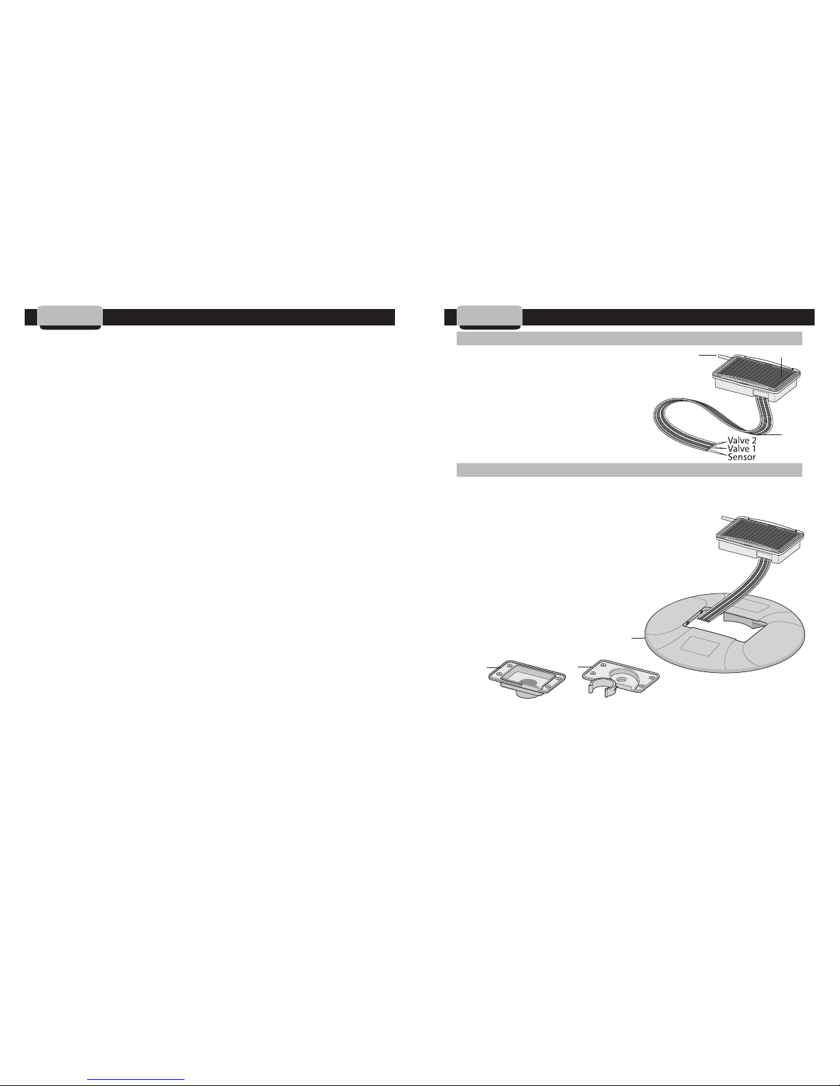
1. PVM Photovoltaic module harnesses the
energy of light and generates the electricity
to power the unit day and night in any of
weather condition
2. Antenna
3. Stations and sensor wires
1.2 System Components
To properly install the LEIT-2 controller, the following components will be
needed:
1. Control unit: LEIT-2, 2 station controller
2. The controller is installed using 1 of 3 mounting
configurations available:
a. Valve box mounting dome, color: green
(Model 30-30)
b. Mounting column bracket
(Model 30-831)*
c. Valve clip attachment
(Model 30-832)
If the mounting column plastic attachment is used, a mounting column is also
needed. Use one of the two following mounting columns: model MCOL2S
(small) 25" (63 cm) or MCOL2L (large) 50" (128 cm) mounting column including
mounting tool kit with cement glue (to firmly attach mounting bracket to
column).
b
d
7
E. Features
• All power is provided by an internal photovoltaic module and
microelectronic energy management system fueled by ambient light
• Multilingual software in English, Spanish, Italian, French, German and
Portuguese
• Controller has a 2-way radio with operating range of up to 350 ft (100
meters) line of sight
• Radio frequency is in the ISM band 902-928 MHz (868 MHz international)
CE and FCC certified
• Default program; if not programmed the controller defaults to 5 minutes per
day (if ID has been entered)
• Manual run via the RC2 handset
• Client ID enables the user to have a unique identity code for the controllers
and handset; this is a security feature, which locks out unauthorized users
• The LEIT-2 operates up to 2 Unimax S-305DC solenoids installed on most
valves using one of DIG’s solenoid valve adapters
• Dedicated Rain Sensor input allows for a sensor connection promoting
better water efficiency
• Electrical protection for up to 50 volts; resistant to damage from lightning
and currents from power lines
• Non-volatile memory retains program integrity indefinitely (excludes time)
• Built from tough, rugged material - resistant to harsh environmental
conditions
• Environmentally friendly: Certified lead free, uses light as a source of
energy
• Waterproof, complies with IP68 requirements
• Mounting configurations include valve mounting, valve box mounting and
column mounting
6
c
c
a
b
Page 5
1.3 Tools and Supply Requirements
1. Standard wire stripper
2. Philips screwdriver (#1) if using the valve clip attachment or the mounting
column plastic attachment or Philips screwdriver (#2) used with the valve
box mounting dome
3. Concrete: approximately 1, 90 lb (40 kg) bag (if using mounting column)
NOTE: Only needed with the mounting column
4. Waterproof wire connectors (not included)
1.4 Quick Installation Setup and Operation Review
In order to establish communication for the first time between a LEIT RC2
handset and LEIT-2 controller the following steps must be taken:
1. Charge the LEIT RC2 handset (see LEIT RC2 instruction)
2. Setup the LEIT RC2 handset (see LEIT RC2 instruction)
3. Install the LEIT-2 controller following the LEIT–2 installation instructions
and let it sit out in the light to harness light energy.
a. In bright light conditions (full sun) this will take under 30 min.
b. In shaded conditions this could take up to 2 hours
c. Communication will only initiate when the controller is fully charged
4. Follow the instructions steps of how to establish initial communication
between a LEIT-2 controller and LEIT RC2 handset.
STEP 1: Connect the two yellow sensor wires together (found on the
LEIT-2 controller) so that the LEIT RC2 remote handset can identify the
new controller (see LEIT RC2 handset operation instruction).
STEP 2: Using the LEIT RC2 Handset, select Default Setup and
connect
to the LEIT-2 controller using Radio Uplink icon (see page 17).
STEP 3: After establishing communication between a LEIT RC2 handset
and a LEIT-2 controller, setup the controller selecting Setup icon found in
the Controller Menu. Then select Cont. Setup icon found in the Setup
Menu Screen (see RC2 handset operation instructions).
9
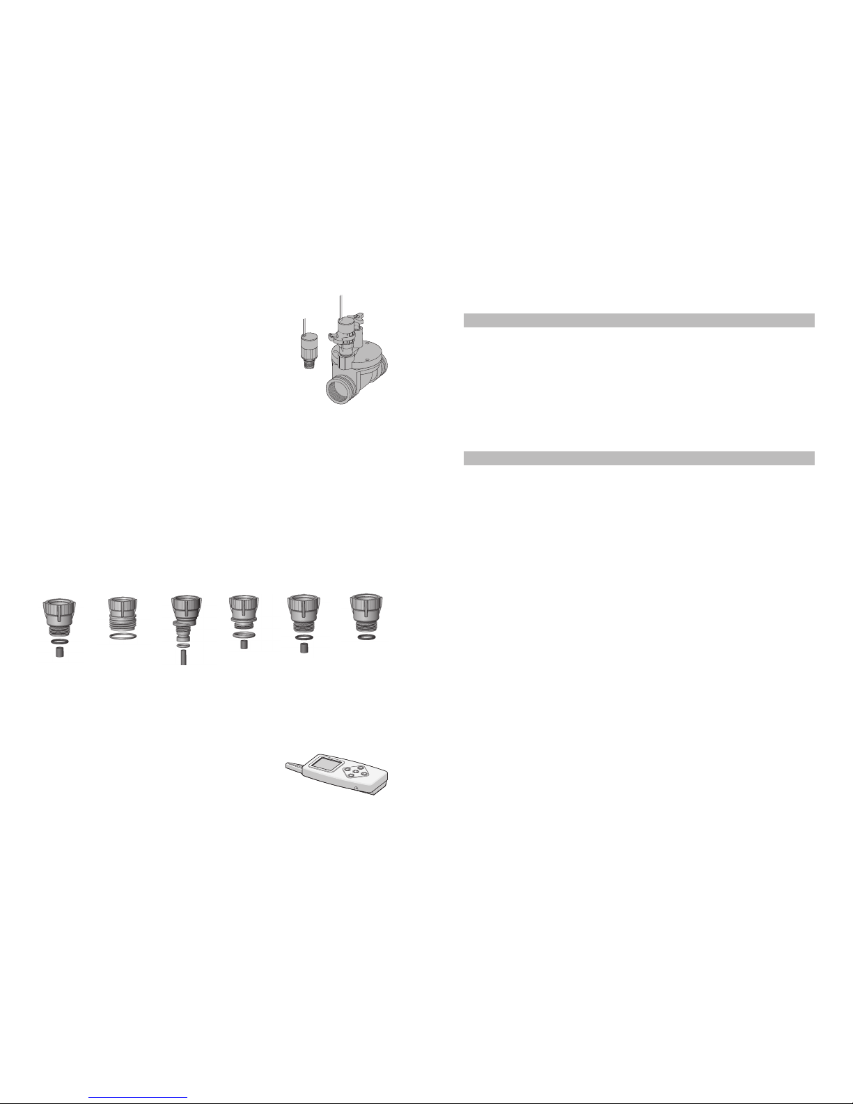
3. 305DC-XXX complete in-line valve with solenoid or
S-305DC solenoid (one for each valve used)
4. 5-solenoid adapters are available to fit most valves:
a. Model 30-920 use with BERMAD 200 series HIT 500
series, Superior 950, Griswold 2000, DW and Hunter HBV
b. Model 30-921 use with RAIN BIRD DV, DVF, PGA, PEB, GB, EFB, BPE,
PESB and ASVF valves
c. Model 30-922 use with HUNTER ASV, HPV, ICV, PGV and AS VF series
valves
d. Model 30-923 use with WEATHERMATIC 12000, 21000 series valves
e. Model 30-924 use with IRRITROL 100, 200B, 205, 217B, 700 2400, 2500
and 2600 series valves and TORO P220, 252 and 220 valves series
f. Model 30-925 use with SUPERIOR 950, HUNTER HBV, TORO 252 (1.5”
and larger) and BUCKNER VB series.
5. LEIT RC2 remote handset (version SW U:1.XX.XX EE 1.XX.XX)
to communicate with up to 99 LEIT-2 controllers.
8
ABCDE F
A1 "O" ring
200-014
model #30-494
A2 Sleeve
model #30-424
B1 “O” ring
200-021
model #03-077
C1 “O” ring
200-012
model #30-495
C2
Long
sleeve
model #30-423
D1 “O” ring
200-015
model #30-494
D2 Sleeve
model #30-424
E1 “O” ring
200-014
model #30-494
E2
Short
sleeve
model #30-422
F1 “O” ring
200-014
model #30-494
Page 6
7. After installation is complete, turn the water supply on and pressurize the
mainline. The valves will open momentarily and then shut off. Test each
valve in manual operation by moving the manual handle from left to right to
open and right to left to close the valve, making sure that the valve is
operating correctly.
8. Splice the solenoid hot wires (red) to the controller incoming station wire
(V1 red). Splice the solenoid white wire to the single incoming white wire
(V1). If needed repeat for the second valve. Use 2 conventional dry-splice
waterproof connectors. Leave slack on each side of the
wires so that repairs can be carried out easily.
NOTE: The solenoid operates only with
2-way normally closed valves.
NOTE: V1 may be identified by label or striped wires.
IMPORTANT:
If a valve remains open in manual operation, you may need to
examine the solenoid adaptor and sleeve to see that they are installed
correctly and the adaptor is firmly secured. Do not over tighten the solenoid to
the valve and do not cross thread the adaptor into the solenoid cavity.
CAUTION: For all valves with built-in internal manual bleed lever, make sure
the lever is in closed position. Do not move the lever after installing the
solenoid with the valve adapter. If the manual lever on the valve is used, it can
damage the adapter or the sleeve causing the valve to stay open.
11
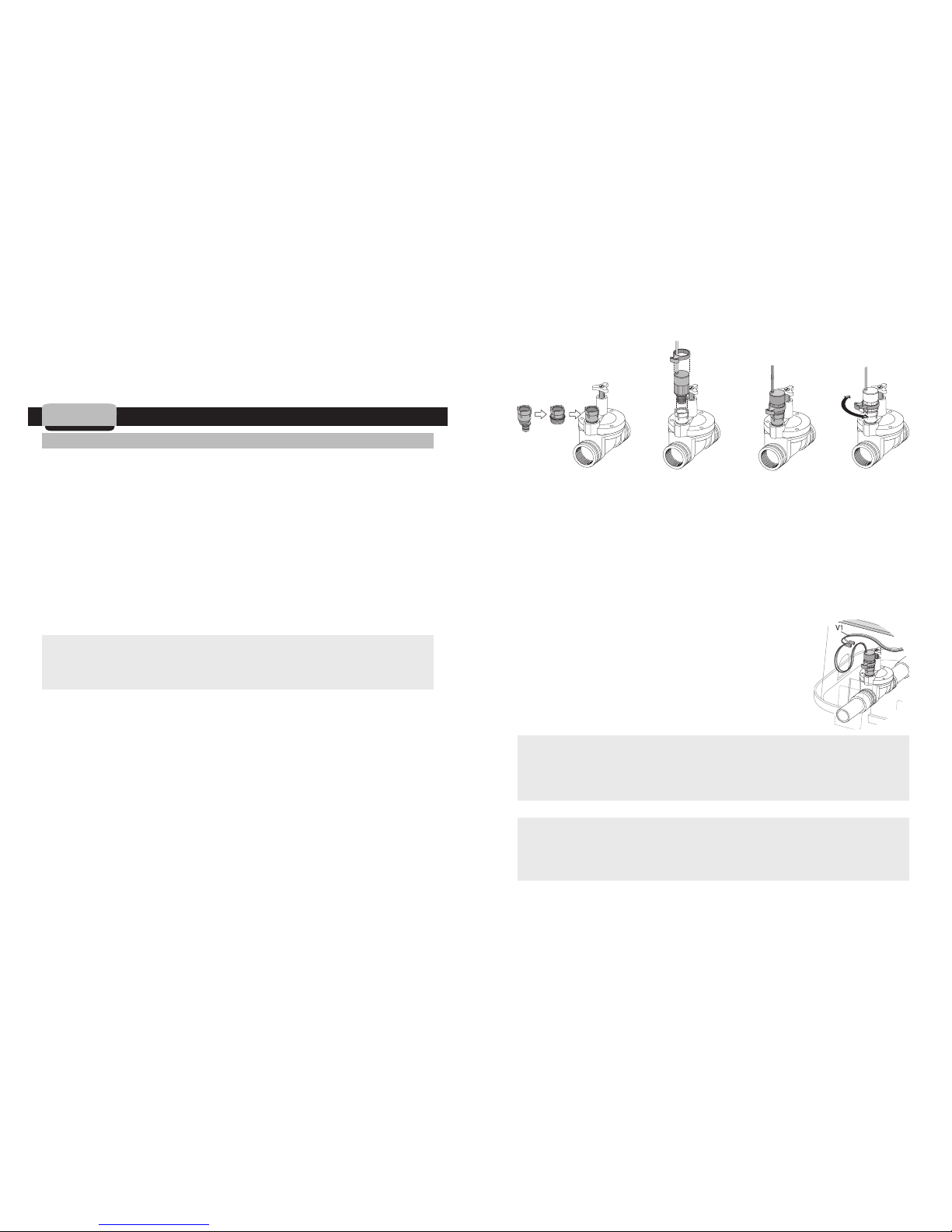
a b b1 c
STEP 4: After setting up the controller, program the controller (See RC2
handset operating instruction)
The handset and controller should now be available for communication
2. Installation
2.1 Solenoid and Valve Installation
NOTE: Maximum operating pressure is up to 150 PSI (10.5 bar)
Use DIG’s 305DC-XXX valve-assembly or Model S-305DC solenoid and select
the appropriate conversion adaptor for the valve(s) that will be used with the
S-305DC solenoid (see list 1.2 #4 on Page 8).
1. Shut off the mainline to the valve.
2. Install valve assembly (model 305DC-XXX) or unscrew the conventional
solenoid from the valve installed and remove the solenoid housing, solenoid
stem, plunger, spring, and “O” ring (if necessary).
3. Select the appropriate conversion adapters for the valve(s) (see list above in
1.2 #4 on pages 8)
IMPORTANT:
Do not remove existing “O” ring on BUCKNER and SUPERIOR
valves.
When installing adaptor on BUCKNER and SUPERIOR valves remove
the adapter sleeve (model 30-424) before installing.
4. Thread and tighten the conversion adapter clockwise to the compatible
valve port, do not over tighten (no tools necessary) (see a).
5. Make sure that the solenoid holder/handle is not inserted onto the solenoid
housing and then, screw model S-305DC solenoid into the selected adapter.
Firmly tighten the solenoid by hand, but do not over tighten (see b).
6. Slip the manual handle into the solenoid housing. Positioning the solenoid
handle at a 40-45° angle towards the valve creates a manual lever; helpful
for manual on/off (see b1-c).
10
Page 7
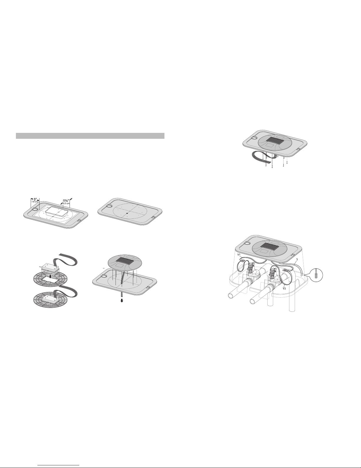
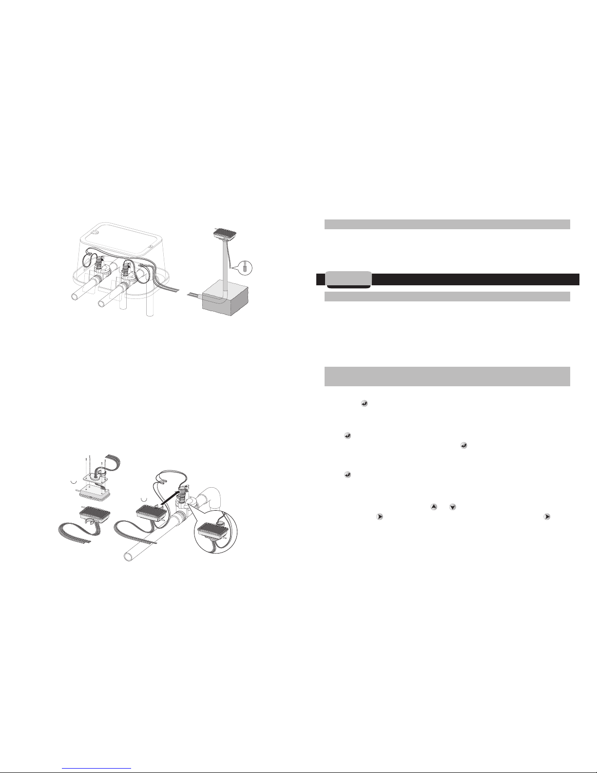
5. There are 6 wires or three sets of wires from the controller, 1 pair for each
valve and 1 pair for sensor connection (labeled V-1, V-2 and S). Connect the
controller’s output station wire (V1 red) to the hot wires (red) on the
solenoid. Then connect the controller’s output station common wire (V1
white) to the white wire on the solenoid using conventional dry-splice
waterproof connectors. Repeat the same steps for station 2. Leave slack in
the wires on each side so repairs can be carried out easily (see 6).
NOTE: V1 may be identified by label or striped wires.
6. Reattach the valve box cover on top of the valve box and if available lock
the cover to the box (recommended) (see 6).
Option B: Mounting Column (model 30-831)
1. Excavate a trench from the valve to the column location and then, pull a set
of colored wires from the valve area to the mounting column location (one
13
2.2 Controller Installation
Option A: Valve Box Mounting Dome, color: green (model 30-830)
1. Lay the template on top of the rectangular or round irrigation box cover and
drill 4-8 holes, make sure to review the template position on the valve box
before drilling (see drilling instruction on the template) using 1/4” drill
(.250”) (6 mm). The holes are used to hold the mounting dome to the
irrigation box cover. Using the same template, drill 1 hole using a 1/2”
(.500”) (12 mm) drill bit to allow the
wires from the controller into the valve
box cover (see 1-4)
2. Insert the controller into the mounting dome (see 3).
3. Insert the controller wires into the valve box cover (see 4).
4. Use #2 Philips screwdriver to attach the mounting dome to the valve box
cover with the #10 Philips head screws that are included with the mounting
dome (see 5).
12
1
2
3
4
5
c
b
d
e
f
g
Detailed Installation
S
Page 8
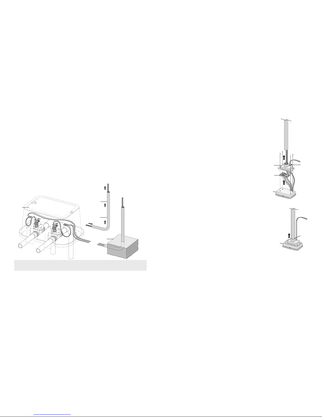
about 3-4" (7-10 cm) from the controller and then,
connect the controller output station wire (V1 red
and white) to the incoming hot wires (#1 red or
colored) using 2 small waterproof wire nuts. If
necessary, repeat the same procedure for valve #2
using the wires labeled V2 (see 5). Next, bring the
two yellow sensor wires through the small hole on
the side of the mounting bracket (see 6). Finally,
place wires with nut inside the bracket body and
secure the plastic bracket into the controller using
the 4 small Phillips screw provided (see 5-6).
5. Next, apply a thin layer of cement glue (included
with the column) to the top on the outside area of
the column and slide the controller-mounting bracket
into place on top of the column (see 7).
6. At the valves, connect the incoming station wire (V1 red) to the hot wires
(red) on the solenoid using conventional dry-splice waterproof connectors.
Connect the controller incoming station common wire (V1 white) to the
white wire on the solenoid using conventional dry-splice waterproof
connectors and if needed repeat for the second valve and sensor. Leave
slack in the wires on each side so that repairs can be carried out easily (see
detailed illustration).
15
pair for each valve). Each pair should consist of one white wire, and one
red or colored wire, preferably of differing colors. Each pair should be
taped and marked separately at both ends, so that the wires do not get
cross-connected (see 1).
2. Insert the pairs of wires through the bottom of the mounting column and
push the wires up through the column until at least 6"
(15 cm) of wire
extends from the top of the mounting column (see 2).
3. Install the mounting column, setting the curved bottom of the mounting
column in an 8" x 8" x 6" (20 x 20 x 15 cm) frame and pour in the 90 lb
(40 kg) sack of cement (see detailed illustration). Make sure the column is
vertical and the opening in the curved bottom is accessible and unclogged
(see 3).
IMPORTANT:
Make sure the cement pad is dry before continuing
installation.
4. Pull the 2 pairs of field wires from the valves through the center hole in the
bottom of the mounting plastic bracket (see 4). There are three sets of
wires from the controller, 1 pair for each valve and 1 pair for sensor
connection (labeled V-1, V-2 and S). First, trim the controller valve wires to
14
2
e
f
g
b
d
h
c
Page 9
2.3. Maximum Wire Run
100’ (30 m) using 18 AWG (0.75 mm) solid core direct burial irrigation wire
200’ (60 m) using 14 AWG (2.5 mm) solid core direct burial irrigation wire
300’ (90 m) using 12 AWG (4 mm) solid core direct burial irrigation wire
3. Initial Communication
3.1 Initiating Communication for the First Time
Use the 2 yellow-colored, sealed sensor wires on the controller to signal to
the LEIT-2 controller that it is about to be programmed. Splice the 2 yellow
sensor wires together using waterproof connectors. This splice will distinguish
that the controller is ready to commnicate with a LEIT RC2 handset. Use the
handset to connect to the controller via the Radio Uplink icon using the default
address.
3.2 Connecting to the LEIT-2 Controller for the First Time Using the
LEIT RC2 Handset
In the LEIT RC2 handset’s main menu press and highlight the RADIO UPLINK
icon. Press and the RADIO UPLINK screen will appear. This is the default
address screen. The description in this screen is: CONTROL ID: 00, DEFAULT
SETUP.
Press to connect to the controller. The ARE YOU SURE? screen will appear
with the Radio Uplink icon selected. Press to connect to the controller
without an ID. After establishing communication, CONNECTED will appear
momentarily and then, CONNECTED TO: CONTROLLER ID: 00, DEFAULT SETUP.
Press again. The UPLOADING screen appears momentarily then, CONT.
SETUP with CONTROL ID: XX (digits flashing), which means the controller’s ID
is available for modification.
To modify the controller ID, press or and enter a number (1-9) for the
first digit. Press and repeat the steps with the second digit. Press to
continue to the next step, setting controller address (the default is
DESCRIPTION). Repeat the steps for selecting the controller address or name.
The final step is to select a Client ID (A-Z) using the same steps. When
17
Option C: Valve Mounting (model 30-832)
1. Slide the wires from the controller into the valve-mounting bracket and
connect the valve-mounting bracket to the controller using the 4 screws
included (see 1).
2. Connect the incoming station wire (V1 red) to the hot wires (red) on the
solenoid using conventional dry-splice waterproof connectors. Connects the
controller incoming station common wire (V1 white) to the white wire on
the solenoid using conventional dry-splice waterproof connectors and if
needed repeat for the second valve and sensor. Leave slack on each side of
the wires so that repairs, if needed can be carried out easily (see 2).
NOTE: V1 may be identified by label or striped wires.
3. Attach the controller into place on the top of the solenoid (see 3).
16
2
1
Detailed Installation
b
c
d
Page 10
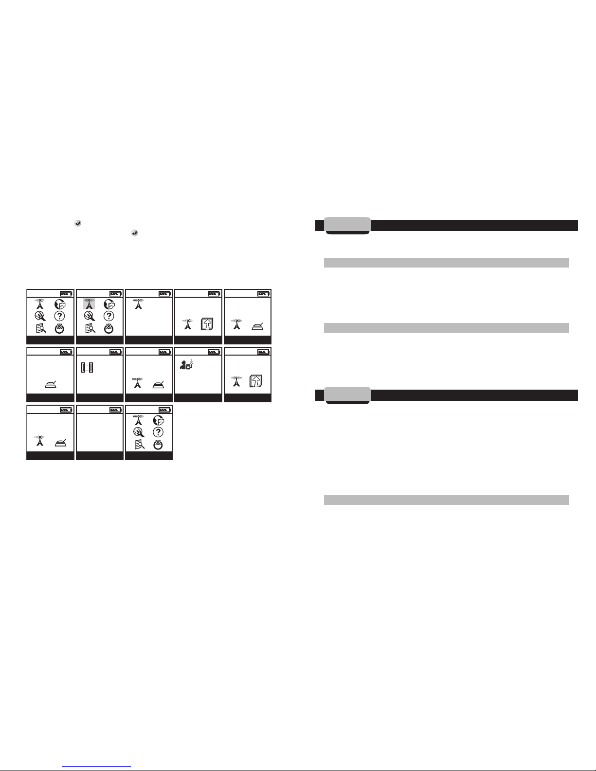
finished, press to connect and upload the new information. The ARE YOU
SURE? screen will appear. Press again to download the information. The
UPDATE SUCCESSFUL message will appear momentarily confirming that
controller setup is updated and complete and then, CONTROLLER MENU
appears.
The controller is ready to program:
Repeat the steps for additional controllers.
NOTE: The user can now easily connect to this controller using the new
assigned controller ID. Repeat the steps to program additional controllers.
NOTE: The 2 yellow sensor wires are left connected, so the controller does not
think it is raining. If a rain sensor needs to be added, see sensor installation below.
4. Using a Sensor
NOTE: Do not install sensor until after the controller has been given an ID #
by the RC-2 handset.
4.1 Sensor Installation
Remove the waterproof connector from the controller's yellow wires and
splice them. Splice the sensor two normally closed (N/C) black wires. Connect
1 of each yellow wire from the controller with 1 of each black wire from the
sensor using waterproof connectors (if sensor is connected, the sensor will
override the program when triggered).
4.2. Compatible Sensors
Sensors compatible with LEIT-2 controllers:
Rain sensors:……HUNTER MINI-CLICK II (model 502) and the RAIN BIRD RSD
Moisture sensors: …………………………IRROMETER RA and TGA series
Freeze sensor: ……………………………………HUNTER FREEZE-CLICK
5. Troubleshooting
The LEIT-2 wireless irrigation control system is a series of components
consisting of LEIT-2 ambient light powered 2 station controller, the RC2
handset, S-305DC solenoids, solenoid adapters, hydraulic control valves, and
wires/splices. It is best to troubleshoot this DC system (like an AC system) by
a process of elimination; the goal being to determine which component(s) has
failed. The following facts and tips may be helpful to eliminate certain
components and facilitate faster troubleshooting. It is assumed that these are
installed controllers that are receiving the proper amount of light. Keep in
mind that the problem may be with more than one component.
5.1 Troubleshooting Controller
1. To test the controller’s output, connect a solenoid to one of the controller’s
red and white wire pairs. Institute a test run via the handset with 1 minute
on the station in question and zero minutes on the other station. If the
solenoid is not installed, verify that the plunger retracts and extends or that
you hear the sound of the plunger latching. If the solenoid is installed onto
1918
10:00 10:00 10:00 10:00 10:00
10:00 10:00 10:00 10:00 10:00
10:00 10:00 10:00
<
>
MAIN MENU RADIO UPLINK RADIO UPLINK YES / NO CONNECT
CONNECT CONNECTED TO: CONNECT CONT. SETUP YES / NO
CONNECT CONNECT CONTROLLER MENU
CONTROL ID: XX
NO DESCRIPTION
ARE YOU SURE? CONNECTING
CONNECTED
CONTROL ID: XX
NO DESCRIPTION
CONTROL ID: XX
NO DESCRIPTION
CLIENT ID: XXX
UPLOADING
CONNECTING
UPDATE
SUCCESSFUL
ARE YOU SURE?
Page 11
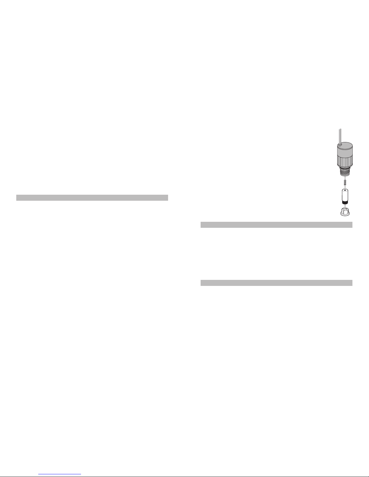
6. If the valve is not opening completely, the adapter
being used with the S-305DC solenoid may be to tight,
the adaptor sleeve could be damaged, or the valve
water passage down stream may be plugged and in
need of cleaning.
7. Solenoid parts list
5.3 Troubleshooting Hydraulic Valves
1. Verify that the valve opens and closes using the manual bleed. If it does
not, the problem is with the valve.
a. Verify that the static mainline pressure at the valve is below 150 PSI
(10.5 bar) and above 10 PSI (.7 bar).
b. Verify that the valve size is correct for the flow rate of the system.
c. The S-305DC solenoid should be installed only on normally closed 2-way
valves.
5.4 Troubleshooting Control Valves
1. Verify that the white common wire is connected to the white common wire
on the controller and that the wire is from the same pair.
2. Verify that common and hot wire splices at the valves or splice boxes are
tight and made with waterproof connectors.
3. 12 and 14 AWG direct burial single strand solid core irrigation wires are
recommended; do not use multi-strand wires.
4. The controller software can detect wire faults or wire shorts.
21
a valve, see that the valve turns on and the sprinklers or drip system is
working. If it does not turn on, the plunger does not retract and extend or
no sound is heard of the plunger latching, repeat the process using a
second solenoid. If the problem continues you may have an issue with the
controller wires and the waterproof connectors.
2. The LEIT-2 controllers will only function with S-305DC solenoid or 305DCXXX valve
3. The LEIT-2 controllers will only function with compatible sensors (HUNTER
MINI-CLICK or RAIN BIRD RSD)
5.2 Troubleshooting Solenoids
1. Verify that the correct solenoid and adapters are being used for the valve in
question.
2. Verify that the white and red wires from the solenoid are connected to the
white and red wire pair on the controller and that these splices are tight,
and corrosion free.
3. Verify that no water is leaking externally near the adapter, stem, or bonnet.
4. Verify that all “O” rings and/or rubber hoses are in place, if in doubt, check
the adaptor and the solenoid.
a. To test S-305DC solenoid, remove the solenoid from the valve and
disconnect the hot and common wires. Verify the solenoid functions
properly using a 9-volt battery by briefly touching the wires to the
positive and negative contacts. Reverse polarity if nothing happens.
Plunger should retract. Reverse polarity to close, (plunger should extend
and a sound of the plunger latching should be heard).
b. If the solenoid does not function with a 9-volt battery, check the battery.
If the problem with the solenoid continues after using a second battery,
it should be replaced.
5. If the valve is weeping or not closing completely, the adapter being used
with the S-305DC solenoid may be loose, cross-threaded, missing an “O”
ring, the adaptor sleeve could be damaged, or the valve diaphragm inside
the valve could be in need of cleaning or replacement.
20
Spring
30-906
Plunger Assembly
30-905
Retainer
30-907
Page 12
22
6. RECORD CHART
Customer ID Controller ID Handset ID Location / Address
Keep this information in a safe place for your records
23
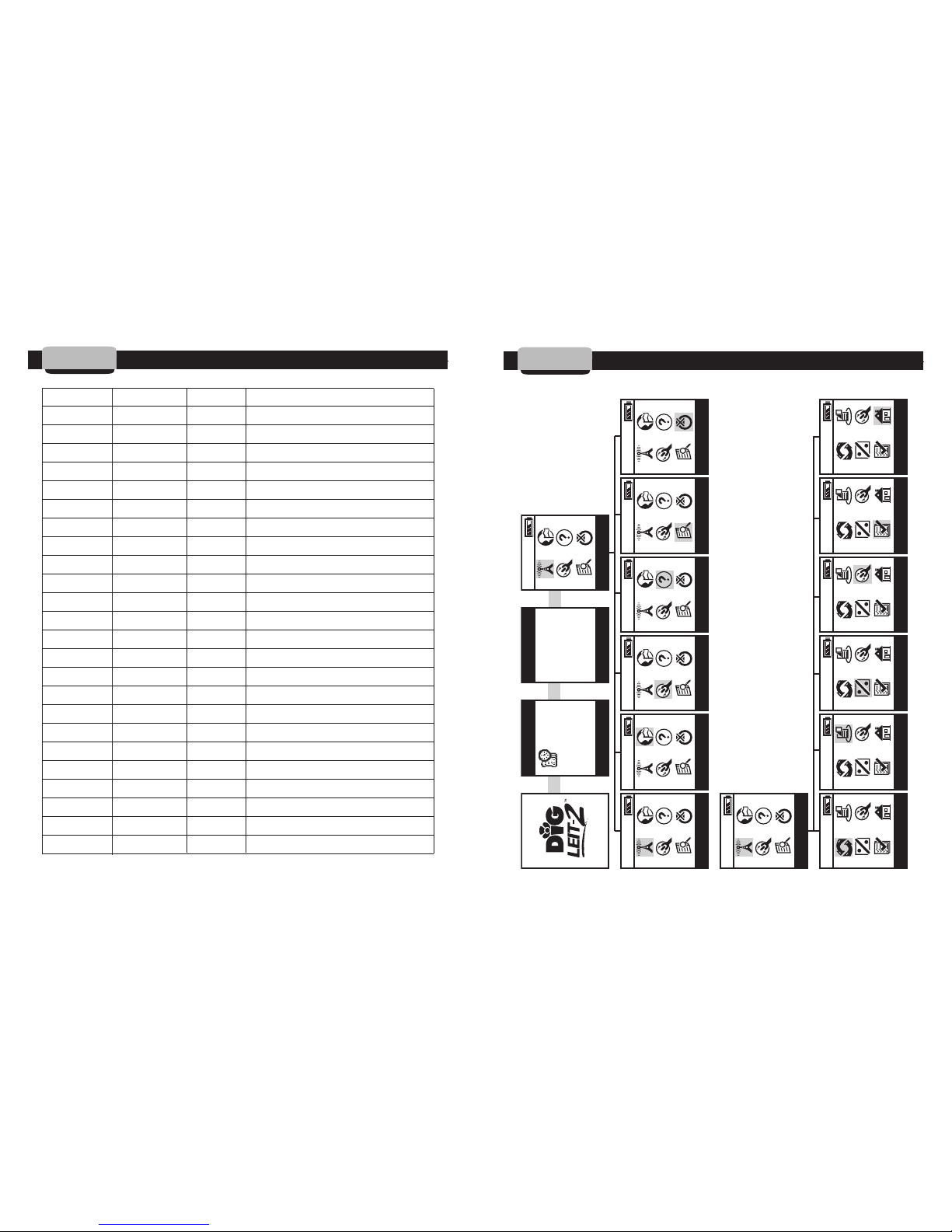
7. PROGRAMMING QUICK REFERENCE CHART
10:00
10:00
10:00 10:00 10:00 10:00 10:00
10:00 10:00 10:00 10:00 10:00 10:00
10:00
RADIO UPLINK
RADIO UPLINK
LANGUAGE SETUP HELP FIND TURN OFF
MANUAL RUN PROGRAM BUDGET SETUP REPORTS EXIT CONTROLLER
TIME / DATE VERSION MAIN MENU
SW V: 1.00.00
EE V: 1.00.00
10:00:00 AM
MONDAY
7/10/2006
 Loading...