

Page 1
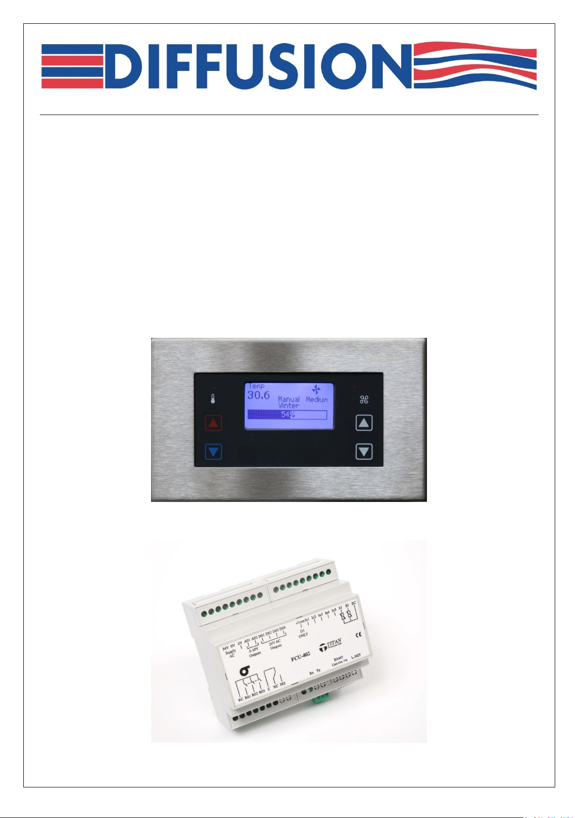
TITAN - Energy Saving Controls – User Manual.
Guidance Notes on:
Controller Features & Operation;
Setting Controller Address & Network ID;
Configuring Stand Alone/Master/Slave;
Configuring Sensor Options;
Set-Point Adjustment.
Page 1 of 29 Titan ESC User Manual r0.docx
Page 2

TITAN - Energy Saving Controls
Controller Overview:
Brief:
The Titan Controller with Diffusions Energy Saving software strategy is designed to be a cost effective
multi-purpose digital control unit fulfilling the requirements for either Electric or Hot Water door
curtain and heating unit types.
The control system consists of a Titan FCU-402 controller mounted within the heating unit, and a room
/ wall mounted RDU-4 user interface / display module; connected to the controller via an RJ11 cable.
Features:
RDU-4 LCD room / wall mounted user interface / display module.
Simple RJ11 plug connection between unit controller and room display module.
Soft-touch button control on RDU-4 for winter / summer changeover, and fan speed selections.
BACnet - RS485 cable connection between multiple units and BMS system.
RS485 network communications, BACnet protocol, for full BMS monitoring and control integration.
User adjustable engineering setting; including Supply air temperature and Room / Return air
temperature.
On/off Volt free contact input for time clock or BMS control.
Display of fan speed, off coil temperature, and % heating output; and Fault conditions.
Adjustable Off Coil set-point, factory default setting of 40°C.
Return Air / Room Thermostat input to reduce or turn off heating when room temperature set-point
reached.
Return air temperature measurement in place of room stat for greater flexibility
High precision supply and return air temperature sensors.
Three fan speed settings, plus off, with silent fan speed switching.
BMS controllable of fan speeds.
Summer/Winter changeover settings.
Option for outside air temperature for fully automatic Summer / Winter changeover control.
On/off input for occupancy sensed control; with adjustable run on time, default 15 minutes.
Direct PID control of valve actuators for water fed systems.
PID control of electric heating elements via external solid-state relays.
Master/slave control of heating output and fan speeds achieved with RS485 twin twisted pair cable
between units / controllers.
Page 2 of 29 Titan ESC User Manual r0.docx
Page 3

TITAN - Energy Saving Controls
Controller Operation Sequence:
Brief:
On / Off and Fan speed function are manually selected via the RDU-4 user interface / display module.
Time clock switching or BMS connection can control these functions remotely.
Summer / Winter operating modes are manually switched selected via the RDU-4 user interface /
display module.
Outside temperature sensor or BMS connection can control this function remotely.
Off coil and Return Air sensors are used to control the temperature of the air leaving the supply grill to
maintain the Off Coil set-point value; for Summer or Winter mode.
However when the Return Air temperature reaches that set-point this turns the heating off; unless the
Set-back temperature has been adjusted, when this feature reduces the Off Coil temperature by the
Set-back value rather than turn the heating off completely.
Control Point Settings:
Feature Factory Setting User Adjustable
Summer Off Coil Temperature 18.0°C Yes
Winter Off Coil Temperature 40.0°C Yes
Summer Return Air / Room Temperature 16.0°C Yes
Winter Return Air / Room Temperature 25.0°C Yes
Off Coil set-back 0.0°C Yes
PIR Sensor – Delay Off 15 mins Yes
Outside Temperature Summer / Winter Change over
OT Summer Set-Point Temperature 20.0°C Yes
OT Winter Set-Point Temperature 15.0°C Yes
Fan run on / cool down timer 3 mins Do Not Adjust
Valve Actuator TPC time 150 sec Refer to Diffusion
Page 3 of 29 Titan ESC User Manual r0.docx
Page 4
TITAN - Energy Saving Controls
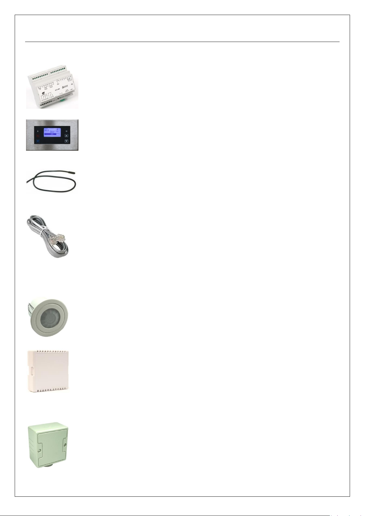
Controller & Interface Components:
Controller 04-ELEC-6494
Room Display Unit 04-ELEC-6486
Air Temp Sensor 2Meter 04-ELEC-6487
5Meter 04-ELEC-6488
RJ11 Cable 5 Meter 04-ELEC-0139
10Meter 04-ELEC-0132
20Meter 04-ELEC-0435
30Meter 04-ELEC-0135
Ceiling PIR Sensor 04-ELEC-6496
Room Temp Sensor (White) 04-ELEC-6497
(Black) 04-ELEC-6550
(Grey) 04-ELEC-6551
Voltage Outside Air Temp Sensor 04-ELEC-6495
Page 4 of 29 Titan ESC User Manual r0.docx
Page 5

TITAN - Energy Saving Controls
Index:
Subject Section:
Controller Settings / Adjustment:
Navigation Buttons: 1.0
Master Unit:
Controller Address: 2.0
Device ID: 2.2
MAC Address: 2.3
Group Number: 2.4
Slave Unit:
Controller Address: 3.0
Device ID: 3.2
MAC Address: 3.3
Group Number: 3.4
Slave Unit Input Settings Adjustments: 4.0
Summer / Winter Off Coil Temperature Adjustments: 5.0
Off Coil Return Air Temp Controlled Set-back: 6.0
Summer / Winter Return Air Temp Set-points: 7.0
Reinstating Slave unit Return Air Temp Sensor 8.0
PIR Sensor Configuration: 9.0
PIR Off Time Delay: 10.0
Time Clock Input NO/NC Polarity Change: 11.0
Interface Setting For Fan Speed Control via BMS: 12.0
Summer / Winter Auto Changeover via VO Temp Sensor 13.0
Adjusting Summer / Winter changeover temp Set-points: 14.0
Operation – RDU-4 Room Display Panel:
Unit Powered, Standby Mode. 20.0
BMS / Time clock, Unit turned On 21.0
Manual Fan 3-Speed Adjustment 22.0
Winter / Summer Operation 23.0
Visual Heating Input % 24.0
Turning the Unit Off & Fan Overrun 25.0
OCT – Off Coil Temperature Sensor Fault 26.0
RAT – Return Air Temperature Sensor Fault 27.0
HTCO – High Temperature Cut-out Fault 28.0
Fault Monitoring – BMS & VFC (Volt Free Contact) 29.0
Controller Input and Outputs, and Wiring Connection Details 30.0
Outside Temperature Sensor Wiring Connections - (TPVOS) 30.1
General Wiring Specifications for Titan BACnet Controls 40.0
BACnet Network Configuration 50.0
Example BACnet MS/TP 3-wire daisy chain configuration 50.1
BACnet Technical Reference
Network Configuration 60.0
Cable Specifications 60.1
Commissioning Settings 60.2
BACnet Device Object Identifier 60.3
MAC Address 60.4
Baud Rate 60.5
Object Descriptions 60.6
BACnet Protocol Implementation Conformance Statement 70.0
Page 5 of 29 Titan ESC User Manual r0.docx
Page 6
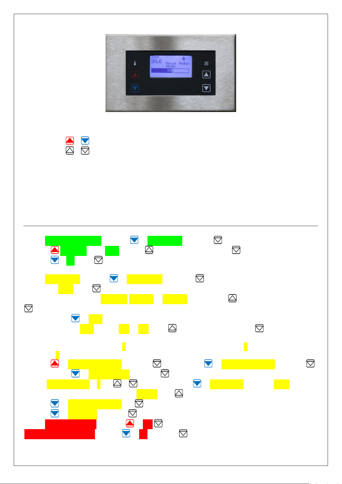
RDU-4 Room Display Panel
Select Buttons
Navigate Buttons
Winter Mode
Summer Mode
Fan Speed Increase
Fan Speed Decrease
1.0 In order to enter engineering mode press all four buttons on the RDU for 3 seconds.
The RDU screen turns to a green (Maintenance Screen).
Left buttons, , navigate through the menus.
Right buttons, , select the options.
1.1 Adjustment of any kind to control parameters not covered in this document should not be made
without written instruction from Diffusion.
1.2 Adjustment of the factory set Safety run-on times should not be made under any circumstances.
NOTE: Highlighted text identifies the RDU-4 screen colour and specific on screen wording
during each stage of the configuration process.
Setting up a Master unit:
2.0 Maintenance Menu; navigate to Setup Menu and select .
Navigate Passcode enter 1212 by using to adjust the numbers, and to move cursor.
Navigate to OK select .
2.1 Setup Menu; Navigate to Unit Specific, and select .
Navigate to FCU4 select .
2.2 Change the Default Device ID 0000000 to 0000001 (unit 1); using to adjust the numbers, and
to move the cursor.
2.3 Navigate to MAC address.
Change the Default MAC address 050 to 011; using to adjust the numbers, and to move the
cursor.
The first number should remain as 0, the second should be the Group number 1, and the third the unit
ID number 1.
Navigate to Return to Previous and select , then navigate to Return to Previous and select .
2.4 Navigate to Control Group and select .
Default Group Number is 1 use & to adjust, Navigate to Group Type, default is None, for a
Stand Alone unit, for a Master adjust to Master using .
Navigate to Return to Previous and select.
Navigate to Exit Menu and select .
2.5 Save all changes ?, Navigate to Yes select,
Send full update to slave navigate to No and select .
Page 6 of 29 Titan ESC User Manual r0.docx
Page 7
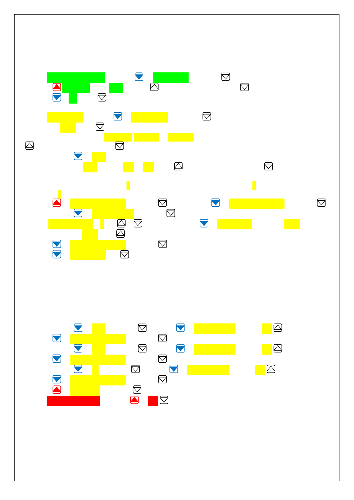
Setting up a Slave unit/s to Operate from Master:
Each Slave controller Device ID and MAC address needs to be uniquely configured.
The RDU remote control plate will need to be plug into each slave controller for programming.
3.0 Maintenance Menu; navigate to Setup Menu and select .
Navigate Passcode enter 1212 by using to adjust the numbers, and to move cursor.
Navigate to OK select .
3.1 Setup Menu; Navigate to Unit Specific, and select .
Navigate to FCU4 select .
3.2 Change the Default Device ID 0000000 to 0000002 (unit 2 for second unit 3 for third etc.); using
to adjust the numbers, and to move the cursor.
3.3 Navigate to MAC address.
Change the Default MAC address 050 to 012; using to adjust the numbers, and to move the
cursor.
The first number should remain as 0, the second should be the Group number 1, and the third the unit
ID number 2 (unit 2 for second unit 3 for third etc.).
Navigate to Return to Previous and select , then navigate to Return to Previous and select .
3.4 Navigate to Control Group and select .
Default Group Number is 1 use & to adjust, Navigate to Group Type, default is None, for a
Slave unit adjust to Slave using .
Navigate to Return to Previous and select .
Navigate to Input Status and select.
Adjusting Slave Unit Input/s Settings to Operate from Master:
Following on from section 3.0 each Slave controller requires three Inputs adjusting to Out of Service to
enable referencing of the Master controller.
4.0 Input settings adjustment enabling reference to Master unit.
4.1 Navigate to In2D and select , navigate to Out of Service, alter to Yes .
Navigate to Return to Previous and select .
4.2 Navigate to In3D and select , navigate to Out of Service, alter to Yes .
Navigate to Return to Previous and select .
4.3 Navigate to S2 and select , navigate to Out of Service, alter to Yes .
Navigate to Return to Previous and select .
Navigate to Exit Menu and select .
4.4 Save all changes ?, Navigate to Yes select,
Note
Stand alone, Master and subsequent Master units on the same network will need to be setup on
separate groups.
Unit ID’s can only be repeated on the same network if they are within a separate group.
Page 7 of 29 Titan ESC User Manual r0.docx
Page 8
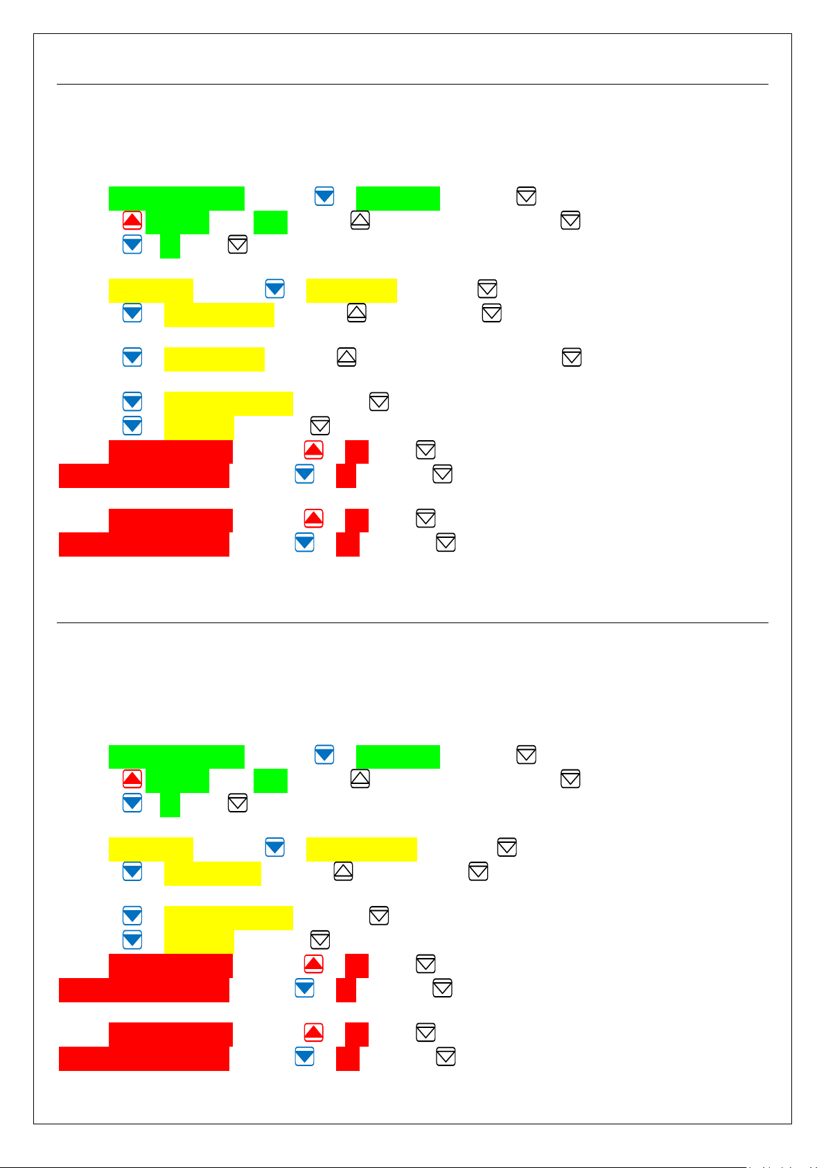
Adjusting Summer & Winter Off Coil Set-Points:
Normal energy saving operation is achieved with the standard factory settings for Off Coil temperature
control; Summer temperature set-point is 18.0°C, and Winter temperature set-point is 40.0°C.
These set-points are user adjustable, but should not exceed the limits detailed below:
5.0 Maintenance Menu; navigate to Setup Menu and select .
Navigate Passcode enter 1212 by using to adjust the numbers, and to move cursor.
Navigate to OK select .
5.1 Setup Menu; Navigate to User Settings, and select .
Navigate to OCT Summer SP and using to increase, and to decrease temperature.
Factory Setting is 18°C Recommended User Range is 15 to 20°C.
Navigate to OCT Winter SP and using to increase temperature, and to decrease temperature.
Factory Setting is 40°C Recommended User Range is 30 to 50°C Do not exceed 50°C.
Navigate to Return to Previous and select .
Navigate to Exit Menu and select .
5.21 Save all changes ?, Navigate to Yes select .
Send full update to slave navigate to No and select . Without Slave unit connected.
5.22 Save all changes ?, Navigate to Yes select .
Send full update to slave navigate to Yes and select . With Slave unit connected.
Adjusting Off Coil Set-Point RAT Controlled Set-back:
Normal energy saving operation is achieved with the standard factory setting of 0°C
By adding a set-back temperature this offsets / reduces the Off Coil Temperature by this value when the
Return Air Temperature is reached; maintaining this as minimum Off Coil Temperature.
These set-points are user adjustable, but should not exceed the limits detailed below:
6.0 Maintenance Menu; navigate to Setup Menu and select .
Navigate Passcode enter 1212 by using to adjust the numbers, and to move cursor.
Navigate to OK select .
6.1 Setup Menu; Navigate to Control Settings, and select .
Navigate to Setback Value and using to increase, and to decrease temperature.
Factory Setting is 0°C Recommended User Range is 5 to 10°C.
Navigate to Return to Previous and select .
Navigate to Exit Menu and select .
6.21 Save all changes ?, Navigate to Yes select .
Send full update to slave navigate to No and select . Without Slave unit connected.
6.22 Save all changes ?, Navigate to Yes select .
Send full update to slave navigate to Yes and select . With Slave unit connected.
Page 8 of 29 Titan ESC User Manual r0.docx
Page 9
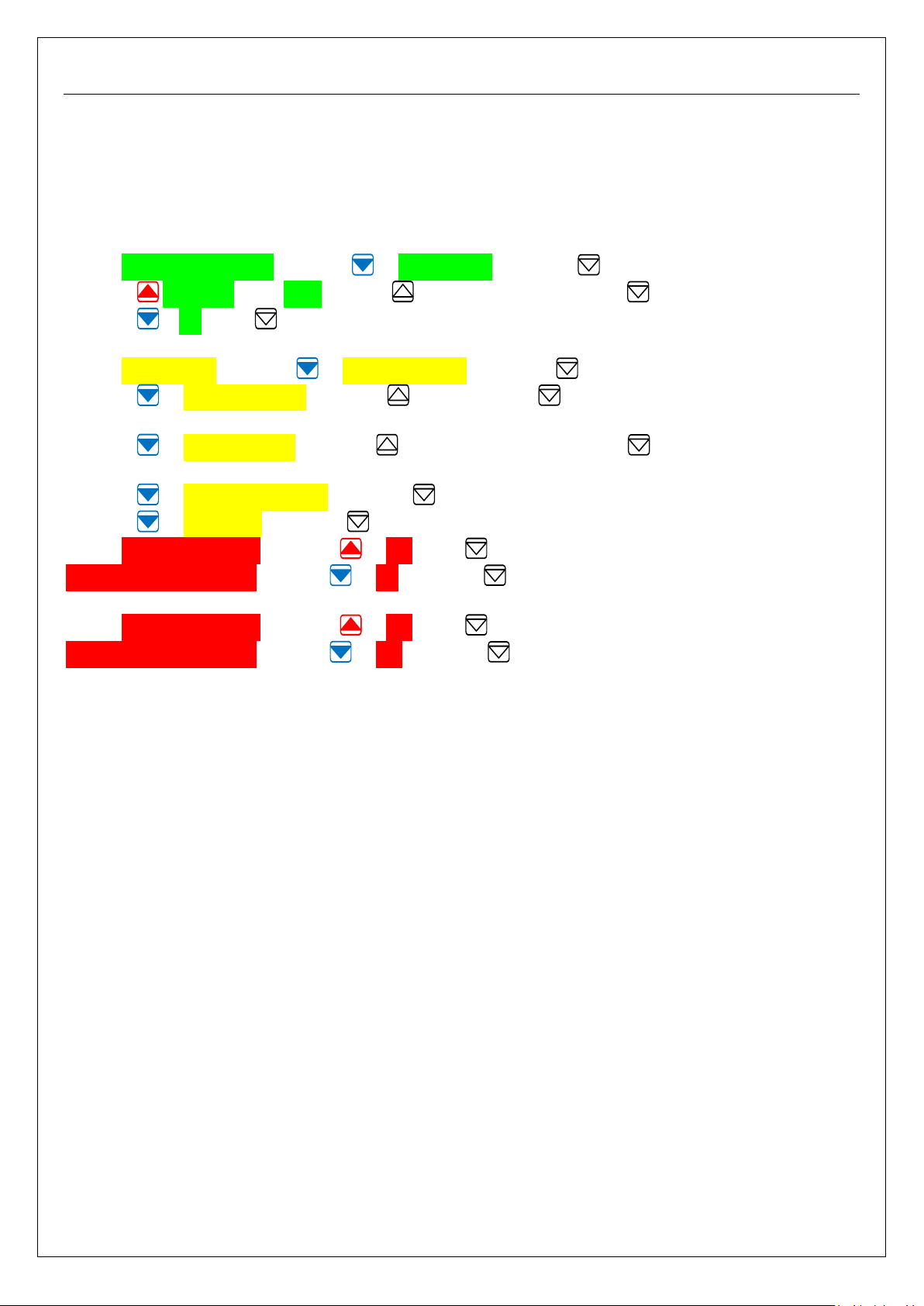
Adjusting Summer & Winter Return Air Temperature Set-Points:
Normal energy saving operation is achieved with the standard factory settings for Return Air
temperature control; Summer temperature set-point is 16.0°C, and Winter temperature set-point is
25.0°C.
It should not be necessary to adjust these set-points; however they are user adjustable, but should not
exceed the limits detailed below:
7.0 Maintenance Menu; navigate to Setup Menu and select .
Navigate Passcode enter 1212 by using to adjust the numbers, and to move cursor.
Navigate to OK select .
7.1 Setup Menu; Navigate to Control Settings, and select .
Navigate to RAT Summer SP and using to increase, and to decrease temperature.
Factory Setting is 16°C Recommended User Range is 14 to 18°C.
Navigate to RAT Winter SP and using to increase temperature, and to decrease temperature.
Factory Setting is 25°C Recommended User Range is 21 to 28°C.
Navigate to Return to Previous and select .
Navigate to Exit Menu and select .
7.21 Save all changes ?, Navigate to Yes select .
Send full update to slave navigate to No and select . Without Slave unit connected.
7.22 Save all changes ?, Navigate to Yes select .
Send full update to slave navigate to Yes and select . With Slave unit connected.
Page 9 of 29 Titan ESC User Manual r0.docx
Page 10
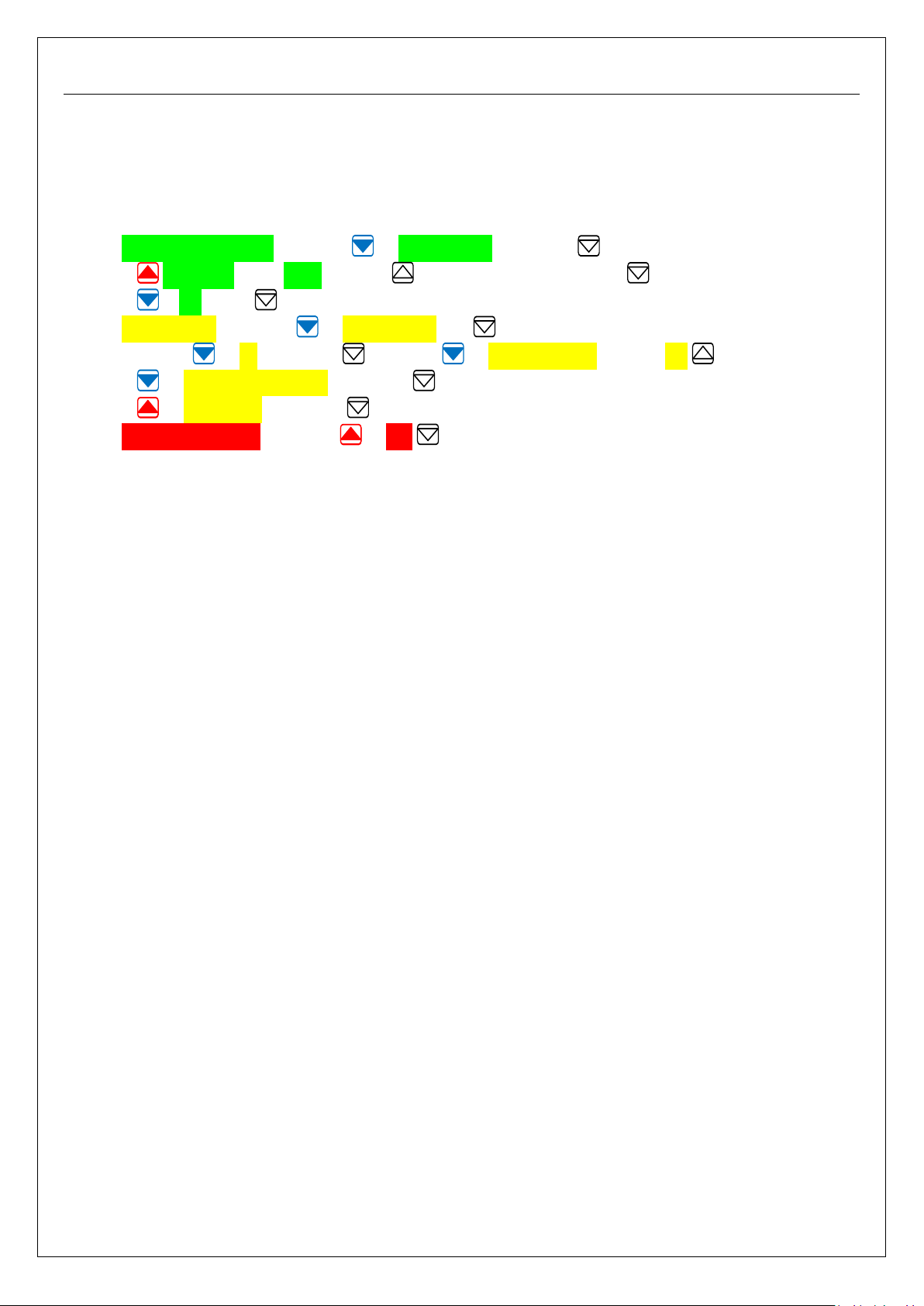
Reinstating a Slave unit/s Return Air Temp Sensor:
As standard the Slave unit is fitted with its own return air sensor which is disabled as standard to suit
close coupled operation; should the units be mounted above separate doors the Slave return air
temperature sensor can be reinstated.
The RDU remote control plate will need to be plugged into each slave controller for programming.
8.0 Maintenance Menu; navigate to Setup Menu and select .
Navigate Passcode enter 1212 by using to adjust the numbers, and to move cursor.
Navigate to OK select .
8.1 Setup Menu; Navigate to Input Status and select.
8.2 Navigate to S2 and select , navigate to Out of Service, alter to No .
Navigate to Return to Previous and select .
Navigate to Exit Menu and select .
8.3 Save all changes ?, Navigate to Yes select,
Page 10 of 29 Titan ESC User Manual r0.docx
Page 11
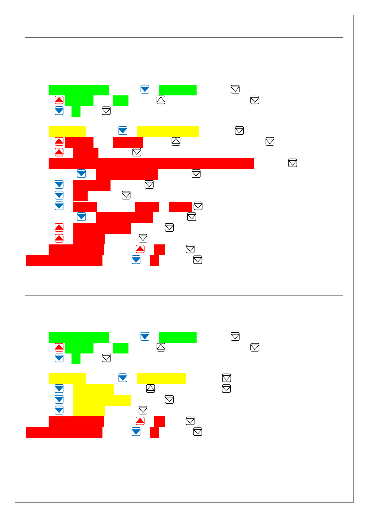
PIR Occupancy Sensor Configuration – Stand-Alone / Master unit:
The Titan Controller strategy is pre-configured to operate with a PIR sensor using the NO contacts to
enable the unit; shutting the unit off when the contacts are closed.
(This can be modified if required by following the sequence below).
9.0 Maintenance Menu; navigate to Setup Menu and select .
Navigate Passcode enter 1212 by using to adjust the numbers, and to move cursor.
Navigate to OK select .
9.1 Setup Menu; Navigate to Configuration Menu, and select .
Navigate Passcode enter 01510151 by using to adjust the numbers, and to move cursor.
Navigate to Proceed and select .
Read: “Please remember to update Software Name if changes are made” and select .
9.2 Navigate to Configuration Menu and select .
Navigate to Input Status and select .
Navigate to In3D and select .
Navigate to Polarity and amend Reverse to Normal .
9.3 Navigate to Return to Previous and select .
Navigate to Return to Previous and select .
Navigate to Exit Menu and select .
9.4 Save all changes ?, Navigate to Yes select .
Send full update to slave navigate to No and select .
Setting / Adjusting PIR Occupancy time delay off:
With the PIR fitted this enables the timed delay off function; this is factory set to 15 minutes, and is fully
adjustable to suit installation requirements.
10.0 Maintenance Menu; navigate to Setup Menu and select .
Navigate Passcode enter 1212 by using to adjust the numbers, and to move cursor.
Navigate to OK select .
10.1 Setup Menu; Navigate to Control Settings, and select .
Navigate to PIR Delay Off and using to increase time, and to decrease time.
Navigate to Return to Previous and select .
Navigate to Exit Menu and select .
10.2 Save all changes ?, Navigate to Yes select .
Send full update to slave navigate to No and select .
Page 11 of 29 Titan ESC User Manual r0.docx
Page 12
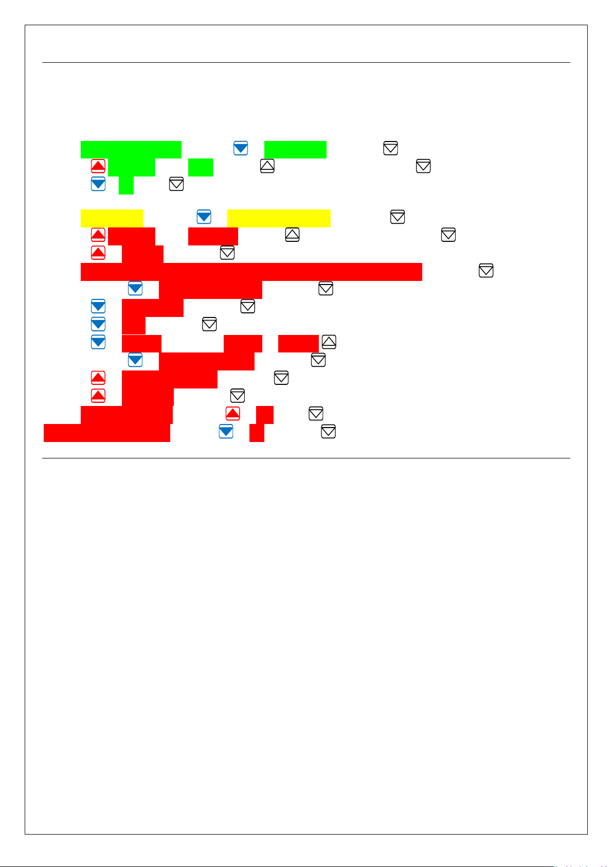
Setting up a Stand Alone / Master for Time Clock:
The Titan Controller strategy is pre-configured to operate with a VFC time clock switch; Open contact
shuts the unit OFF and Closed contact turns the unit ON.
(This function can be reversed if required by following the sequence below).
11.0 Maintenance Menu; navigate to Setup Menu and select .
Navigate Passcode enter 1212 by using to adjust the numbers, and to move cursor.
Navigate to OK select .
11.1 Setup Menu; Navigate to Configuration Menu, and select .
Navigate Passcode enter 01510151 by using to adjust the numbers, and to move cursor.
Navigate to Proceed and select .
Read: “Please remember to update Software Name if changes are made” and select .
11.2 Navigate to Configuration Menu and select .
Navigate to Input Status and select .
Navigate to In2D and select .
Navigate to Polarity and amend Normal to Reverse .
11.3 Navigate to Return to Previous and select .
Navigate to Return to Previous and select .
Navigate to Exit Menu and select .
11.4 Save all changes ?, Navigate to Yes select .
Send full update to slave navigate to No and select .
Page 12 of 29 Titan ESC User Manual r0.docx
Page 13
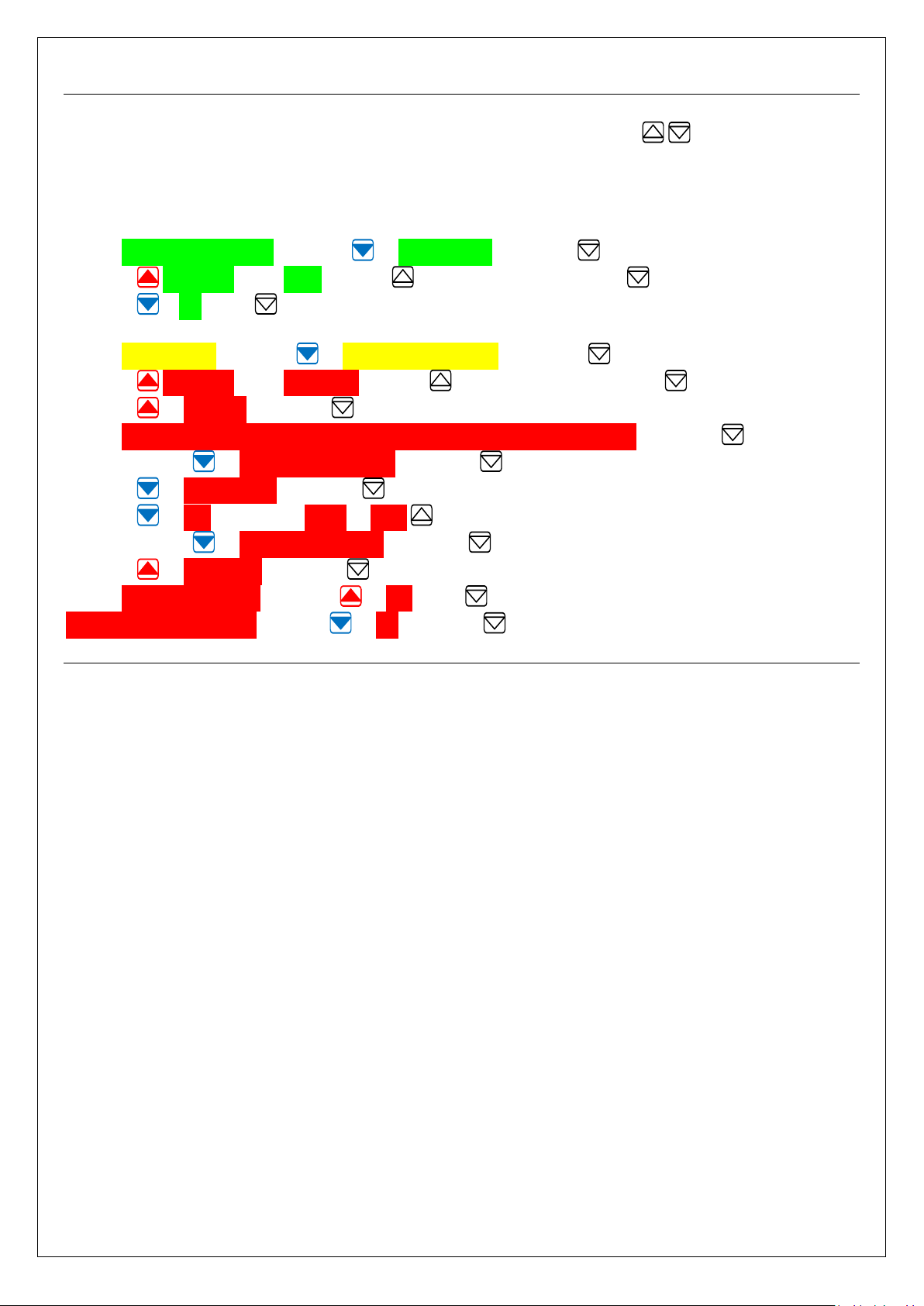
Setting up a SA / Master for a 0-10Vdc / BMS signal for Fan Speed Control:
The Titan Controller strategy is pre-configured to adjust fan speed using the Select buttons.
Sequence: Off – Low – Medium – High.
(This can be amended to operate from a 0-10Vdc signal following the sequence below).
(Fan Off = 0V, Low Speed = 3V, Medium Speed = 5V & High Speed = 7V).
12.0 Maintenance Menu; navigate to Setup Menu and select .
Navigate Passcode enter 1212 by using to adjust the numbers, and to move cursor.
Navigate to OK select .
12.1 Setup Menu; Navigate to Configuration Menu, and select .
Navigate Passcode enter 01510151 by using to adjust the numbers, and to move cursor.
Navigate to Proceed and select .
Read: “Please remember to update Software Name if changes are made” and select .
12.2 Navigate to Configuration Menu and select .
Navigate to Input Status and select .
Navigate to Fan and amend None to In4A .
12.3 Navigate to Return to Previous and select .
Navigate to Exit Menu and select .
12.4 Save all changes ?, Navigate to Yes select .
Send full update to slave navigate to No and select .
Page 13 of 29 Titan ESC User Manual r0.docx
Page 14
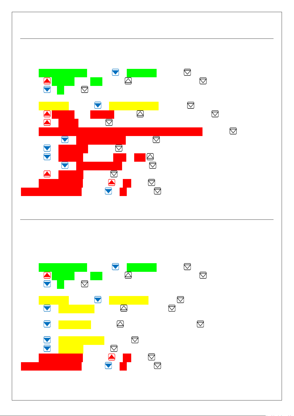
Setting up a Stand Alone / Master for;
Voltage Out-side Temp Sensor – Summer / Winter auto changeover:
The Titan Controller settings require adjustment to allow the Winter / Summer auto changeover
operation, via a 0-10Vdc signal from the VOTS.
13.0 Maintenance Menu; navigate to Setup Menu and select .
Navigate Passcode enter 1212 by using to adjust the numbers, and to move cursor.
Navigate to OK select .
13.1 Setup Menu; Navigate to Configuration Menu, and select .
Navigate Passcode enter 01510151 by using to adjust the numbers, and to move cursor.
Navigate to Proceed and select .
Read: “Please remember to update Software Name if changes are made” and select .
13.2 Navigate to Configuration Menu and select .
Navigate to Input Status and select .
Navigate to OT Sensor and amend None to In5A .
13.3 Navigate to Return to Previous and select .
Navigate to Exit Menu and select .
13.4 Save all changes ?, Navigate to Yes select .
Send full update to slave navigate to No and select .
Adjusting Summer / Winter changeover temperature Set-Points:
Normal energy saving operation is achieved with the standard factory settings for outside temperatures;
OT Summer temperature set-point is 20.0°C, and OT Winter temperature set-point is 15.0°C.
It should not be necessary to adjust these set-points; however they are user adjustable, but should not
exceed the limits detailed below:
14.0 Maintenance Menu; navigate to Setup Menu and select .
Navigate Passcode enter 1212 by using to adjust the numbers, and to move cursor.
Navigate to OK select .
14.1 Setup Menu; Navigate to Control Settings, and select .
Navigate to OT Summer SP and using to increase, and to decrease temperature.
Factory Setting is 20°C Recommended User Range is 18 to 22°C.
Navigate to OT Winter SP and using to increase temperature, and to decrease temperature.
Factory Setting is 15°C Recommended User Range is 13 to 17°C.
Navigate to Return to Previous and select .
Navigate to Exit Menu and select .
14.2 Save all changes ?, Navigate to Yes select .
Send full update to slave navigate to No and select .
Page 14 of 29 Titan ESC User Manual r0.docx
Page 15
TITAN - Energy Saving Controls
Operation:
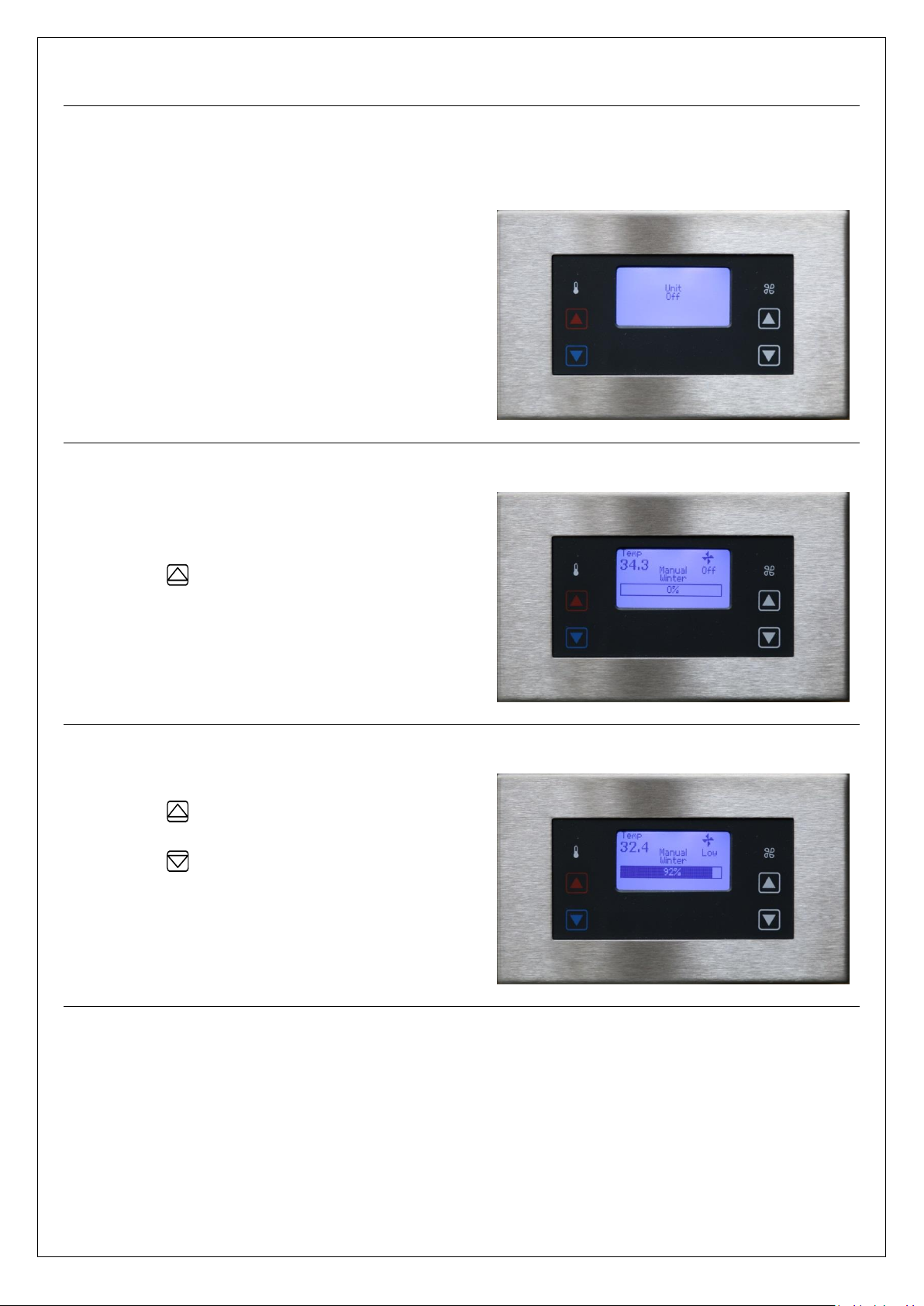
RDU-4 Room Display Panel
Unit Powered, and in Standby Mode.
20.0 BMS or time clock interface signal
switching unit into Off condition.
BMS / Time clock, Unit turned On.
21.0 BMS or time clock interface signal
switching unit into On condition.
21.1 Press to turn fan on – Low.
Manual Fan 3-Speed Adjustment.
22.0 Press to increase fan speed.
22.1 Increase fan; Low – Medium – High
22.2 Press to decrease fan speed
22.3 When the unit is connected on a BACnet
BMS system the fan ON, OFF and Speed setting
can be dictated via the network.
Page 15 of 29 Titan ESC User Manual r0.docx
Page 16
TITAN - Energy Saving Controls
Operation- Cont.:
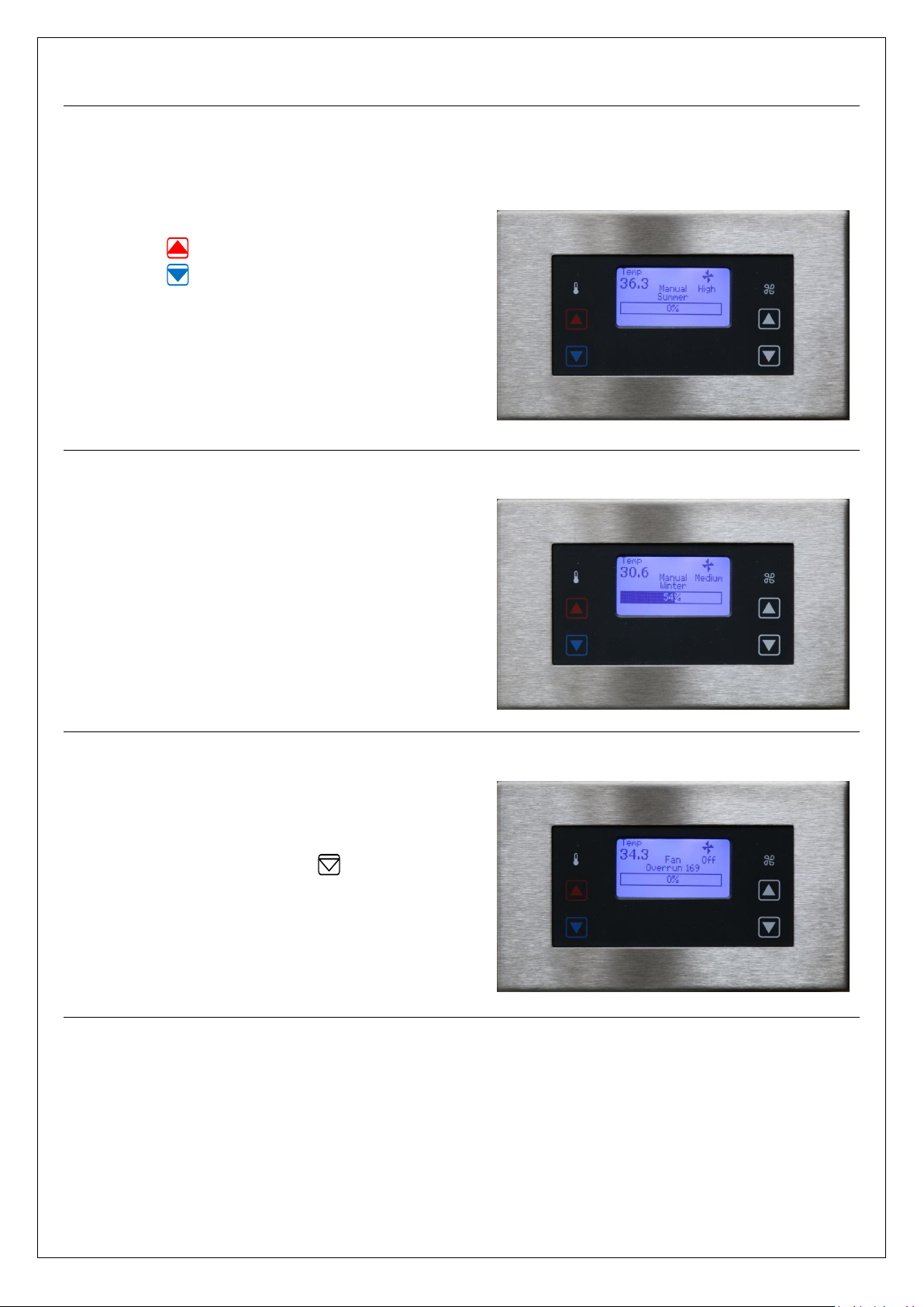
Winter / Summer Operation.
23.0 Press for Winter operating mode.
23.1 Press for Summer operating mode.
23.2 When the unit is connected on a BACnet
BMS system the Winter / Summer operational
setting can be dictated via the network.
23.3 Winter / Summer changeover is
automatic wired to an outside temperature
sensor.
Visual Heating Input %.
24.0 During operation the heat input
required to meet duty demand is indicated by
increased size of the central band across the
RDU screen, and detailed as a percentage of
the unit output.
Turning the Unit Off & Fan Overrun.
25.0 BMS or time clock interface signal can
be used to disable the unit.
25.1 For manual control press to decrease
fan speed till the fan Off position is reached.
25.2 When turned Off the unit will continue
operating in the Fan Overrun state for three
minutes to dissipate residual heat from the
unit.
Page 16 of 29 Titan ESC User Manual r0.docx
Page 17
TITAN - Energy Saving Controls
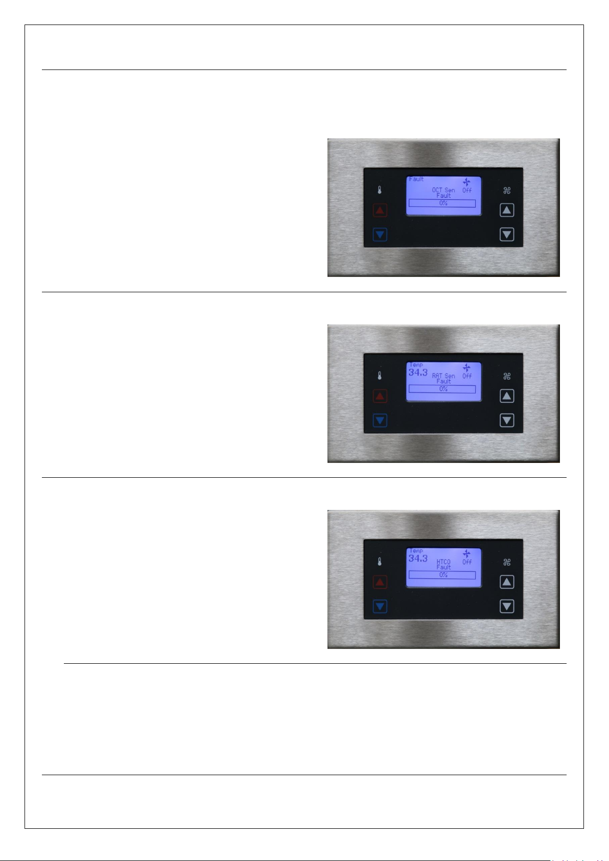
Fault Conditions & Alarms:
OCT – Off Coil Temperature Sensor Fault.
26.0 Screen indication for Off Coil
Temperature fault – “OCT”.
26.1 Unit turns Off, and fan overrun
initiated.
26.2 Upon correction of fault, indication will
automatically reset; unit will be in Off status.
RAT – Return Air Temperature Sensor
Fault.
27.0 Screen indication for Return Air
Temperature fault – “RAT”.
27.1 Unit turns Off, and fan overrun
initiated.
27.2 Upon correction of fault, indication will
automatically reset; unit will be in Off status.
HTCO – High Temperature Cut-out Fault.
28.0 Screen indication for Off Coil
Temperature fault – “HTCO”.
28.1 Unit turns Off, and fan overrun
initiated.
28.2 Upon correction of fault, indication will
automatically reset; unit will be in Off status.
Fault Monitoring – BMS & VFC.
29.0 When the unit is connected on a BACnet BMS system any fault status indication will be
visible via the network.
29.1 Additionally the controller includes a CO-VFC (changeover, Volt free contact), allowing
wiring for a remote alarm indication; Alarming for all conditions as a General fault.
Page 17 of 29 Titan ESC User Manual r0.docx
Page 18
TITAN - Energy Saving Controls
0-10V Outside Temp Sensor (-10+40°C)*
Off Coil Temp Sensor (OCT) 10K3
Return Temp Sensor (RA) 10K3
24V TPC - Open
24V TPC - Close
PWM 24V
PWM 24V
PWM 0-10V
Heat 0-10V
24V Supply
Allocated input on controller
0V
2nd 0V on controller
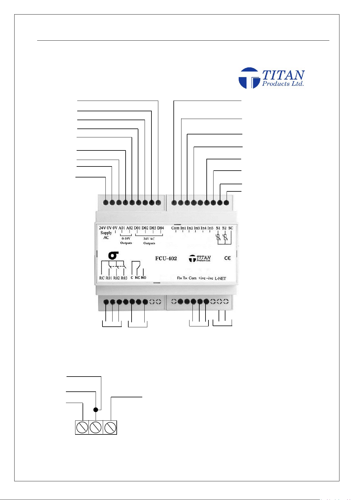
30.0 - TP1193 Diffusion Door Heater Controller – Wiring Diagram
Firmware: 4.16 Software: DHC1.2
30.1 - TPVOS Outside Temperature Sensor (-10+40°C) Wiring
Note: It is important to ground the sensor to the second 0V on the controller.
10K3 Temp Sensor Common
2nd 0V
High Temperature Cut Out (can be
allocated to any input)
24V Supply
24V
GND
0-10V
o/p
*Allocate in configuration menu / input status if required.
Remote ON/OFF
Volt Free PIR Input
0V
Com for digital inputs only
Fan Relay
Fault
Indication
BACnet
MS/TP
RDU
Controller IO’s and Wiring Connection Details:
Page 18 of 29 Titan ESC User Manual r0.docx
Page 19

TITAN - Energy Saving Controls
Item
Cable Spec & Reference
Requirements
BACnet Communications to
BMS Router and between
Master - Slave Controllers
Belden 9841 (0.2mm2) Twisted Pair with
Drain wire and foil wrap or equivalent
Must Be suitable for RS485 Standard
Daisy Chain Network Configuration Only
The cable shield must be connected to
Earth ground at the network router end
only.
Plug In lead between FCU4 &
RDU4
Flat 6 way FCC Cable with Crimped RJ11
6P6C Plugs
Plugs crimped straight through. Max
Cable length 30m
Resistive 2 Wire Temperature
Sensors
2 Core twin twisted screened:- 0.75mm 1mm
Belden 8760 (0.82mm2) or Equivalent
Screen Earthed at Controller end only
0-10v Co2, Temperature or
Humidity Sensors
2 Core twin twisted screened:- 0.75mm 1mm
Belden 8760 (0.82mm2) or Equivalent
Screen Earthed at Controller end only
Combined 0-10v CO2 &
Temperature Sensors
4 Core Screened:- 2 x Twisted Pair:-
0.75mm -1mm
Belden (0.82mm2) or Equivalent
Screen Earthed at Controller end only
ACO Auto/Open/Close Room
Override & temp Sensor
6 Core Screened:- 3 x Twisted Pair:-
0.75mm -1mm
Belden 9773 (0.82mm2) or Equivalent
Screen Earthed at Controller end only
Valve and Damper Actuators
4 Core Screened:- 2 x Twisted Pair:-
0.75mm -1mm
Belden (0.82mm2) or Equivalent
Note: This depends on the type and
number of actuators being used. Check
requirements with Actuator
manufacturer before installation
Screen Earthed at Controller end only
Digital inputs :- PIR’s /
Condense Sensor / Fan prove/
On-Off Switch
2 Core twin twisted screened:- 0.75mm 1mm
Belden 8760 (0.82mm2) or Equivalent
Screen Earthed at Controller end only
Rain Detector
4 Core Screened:- 2 x Twisted Pair:-
0.75mm -1mm
Belden (0.82mm2) or Equivalent
Screen Earthed at Controller end only
General Wiring Specifications for Titan BACnet Controls:
40.0 - Cable Specifications
- All Low voltage cables must be segregated from any mains carrying inductors and they should not be run in the
same containment system
- All low voltage cables must not run in close proximately to any mains AC inductive loads such as florescent
fittings and electric motors
Page 19 of 29 Titan ESC User Manual r0.docx
Page 20
TITAN - Energy Saving Controls
BMS Network Controller
or Router
Titan BACnet enabled
controller
Titan BACnet enabled
controller
750mA Fuse on the
secondary input supply
lines
Please ensure all
polarities on the
secondary of the
transformers are
observed (DO NOT
CROSSOVER)
Com + -
Com + -
Com + -
120 ohm Resistor
(normally)
120 ohm Resistor (often software
selected within network routers and
controllers. Check with router
manufacturer)
Screen
Screen
Terminal
24V 0V
24V 0V
24V 0V
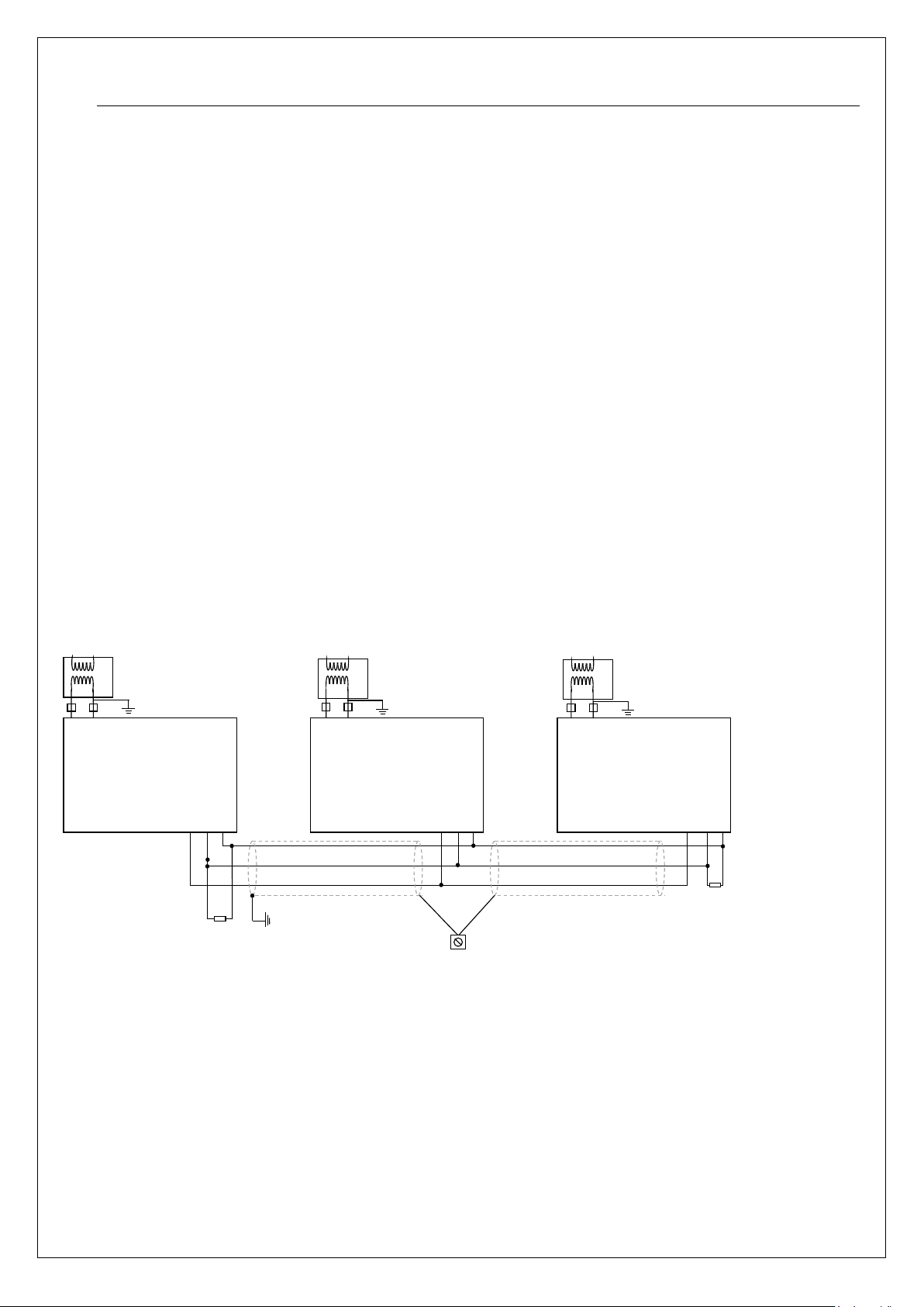
The above diagram shows a typical 3-wire daisy chain configuration. For all BACnet standard wiring variants please consult ASHRAE wiring standards.
BACnet Network Configuration:
50.0
Based on the standards for RS485 networks a BACnet MS/TP network layer allows for only a daisychained network configuration, consisting of a single cable routed between controllers. Star and
Ring network topologies are not supported.
The network electrically supports a maximum of 127 nodes, however BUS network size capability is
determined by factors such as network traffic and BMS capabilities and we recommend maximum
network size of 32 or 64 devices.
To comply with the EIA-485 standard, the maximum number of nodes per segment shall be 32 and
any additional nodes will require the use of repeaters. If only Titan controllers are on the MS/TP
network, the number of controllers may be increased but this will depend on the network traffic,
the baud rate being used and the length/route of the cable.
A termination resistor of 120 ohms should be connected at each of the end devices, when a
network is connected to a Router or BMS this becomes one of the end devices. Please check with
the Router/BMS manufacturer if the 120 ohms end of line resistor is fitted internally.
50.1
Page 20 of 29 Titan ESC User Manual r0.docx
Page 21

TITAN - Energy Saving Controls
BACnet Technical Reference:
60.0 - Network Configuration
MS/TP allows for only a daisy-chained network configuration, consisting of a single cable routed between controllers.
Star and Ring network topologies are not supported.
The network supports a maximum of 254 nodes; addresses 0 to 127 are valid for both master and slave nodes and
addresses 128 to 254 are valid only for slave nodes.
To comply with the EIA-485 standard, the maximum number of nodes per segment shall be 32 and any additional nodes
will require the use of repeaters. If only Titan controllers are on the MS/TP network, the number of controllers may be
increased to 127 dependent on wiring length as specified below.
A termination resistance of 120 ohms shall be connected at each of the two ends of the segment medium.
60.1 - Cable Specifications
The cable used in an MS/TP EIA-485 network should conform to the following specifications:
Wire Size: 22-24 AWG
Cable Type: Twisted-pair, copper wire, tinned and a ground wire which must be connected to all devices on the
485 network.
Shield: Foil or braided
Nominal Impedance: 100 – 130
Capacitance: < 100 pF/m distributed capacitance between conductors
< 200 pF/m distributed capacitance between conductors and shield
Max segment length: 1200 meters (4000 feet)
The cable shield must be connected to Earth ground at the network router end only.
The recommended cable is Belden 3106A.
60.2 - Commissioning Settings
The BACnet commissioning settings can be accessed on the graphical RDU or programming tool by simultaneously
pressing all four buttons. The left buttons can be used to scroll through the menu selections and the right buttons to
change settings. To navigate and access the engineers settings please see supporting documentation.
The following settings need to be commissioned before connection to the MS/TP network:
60.3 - BACnet Device Object Identifier: This setting allows the entry of a unique internet work wide BACnet Device
Object Identifier. With a default setting of 0000000, the device will operate on the local MS/TP network but will not
dynamically bind and initiate I_Am messages. A valid Device Object ID in the range 1 to 4194302 can be entered and
this will set the Device Object Name to “FCU4 DevObjectID”.
60.4 - MAC Address: This setting corresponds to a unique MAC address on the local MS/TP network and can be in the
range 1 to 127.
60.5 - Baud Rate: This setting corresponds to the MS/TP network Baud Rate and should match all other devices on the
same local network. Options are 9600, 19200, 38400 and 76800.
Page 21 of 29 Titan ESC User Manual r0.docx
Page 22

60.6 - Object Description
Object ID
Object Name
Function
Inputs
BI1
In1D
Digital input
B12
In2D
Digital input
B13
In3D
Digital input
B14
In4D
Digital input
BI5
In5D
Digital input
AI100
S1
Sensor thermistor input (Default OCT sensor)
AV100
S1 Offset
Sensor offset
AI101
S2
Sensor thermistor input (Default RAT sensor)
AV101
S2 Offset
Sensor offset
AI1
In1A
Analogue input
AI2
In2A
Analogue input
AI3
In3A
Analogue input
AI4
In4A
Analogue input
AI5
In5A
Analogue input (Default OT sensor)
Outputs
BO1
DO1
Triac1 output (Default TPC Open)
BO2
DO2
Triac2 output (Default TPC Close)
BO3
DO3
Triac3 output (Default PWM)
BO4
DO4
Triac4 output (Default PWM)
BO5
Aux Relay
Relay output
AO1
AO1
Analogue output (Default 0-10V valve actuator)
AO2
AO2
Analogue output (Default 0-10V PWM)
MSO1
3-Stage Relay
Fan relay
Control Settings
AV400
RAT Summer SP
Return air summer set point
0-50DegC
AV401
RAT Winter SP
Return air winter set point
0-50DegC
AV402
OT Summer SP
Outside air summer set point
-10-40DegC
AV403
OT Winter SP
Outside air winter set point
-10-40DegC
AV404
Setback Value
Setback temperature for OCT set point
0-50DegC
BV405
RAT Ctrl
Option for fan off / setback SP when RAT is at set point
0 – Setback
1- Fan Off
AV406
Max OCT SP
Maximum OCT setpoint
0 – 70DegC
AV407
Min OCT SP
Minimum OCT setpoint
0 – 70DegC
AV408
Pb
Heating proportional band
0 – 25DegC
AV409
It
Heating integral time
0 – 20min
AV410
Slew
Heating slew rate
0 – 300sec
The tables below indicate the Objects supported and the functions they perform.
Page 22 of 29 Titan ESC User Manual r0.docx
Page 23

AV411
PIR Delay Off
Occupancy time when the PIR is active
0 – 30min
AV412
Init Time
Time elapsed on switch on before outputs are enabled
0 – 10sec
MSV413
Fan Ctrl
Fan control when RAT setback is active:
1 – Off (Fan switches off immediately)
2 – Overrun (Fan switches off after any overrun has expired)
3 – On (Fan stays on)
AV414
Fan Overrun
Fan overrun time
0 – 60min
MSV415
Fan Position
Fan position:1 –Off, 2 – Low, 3 – Medium, 4 - High
AV416
Setback Time
The time required for any setback status change
0 – 60min
User Settings
BV500
Mode
Mode: 0 – Winter, 1 - Summer
AV501
OCT Summer SP
Off coil summer set point
10-70DegC
AV502
OCT Winter SP
Off coil winter set point
10-70DegC
User Interface
BV600
Occ
Occupancy: 0 – Unoccupied, 1 - Occupied
AV601
Maint Passcode
Maintenance passcode (0000)
AV602
Setup Passcode
Setup passcode (0000)
BV603
Fan Display
Fan display: 0 – Number, 1 - Text
AV604
Backlight Time
RDU backlight time after key press
0 – 500sec
BV605
Display DegC
RDU displays DegC: 0 – No, 1 - Yes
AV606
SP Adjust
OCT setpoint adjust: +/- 100DegC
Misc
BV0
Flash store
Set True to store current values to flash memory so that they are
not lost following a reboot
BV1
Build Fail
Is set to True if the primary configuration file fails to build. Unit
will run on the secondary configuration until the unit is updated
Triac 1
AV220
TPC time
Period (0-360s)
AV222
TPC Accuracy
Accuracy (0-10%)
AV223
Heat %
Current % position
Triac 2
AV230
PWM time
Period (0-360s)
AV233
Heat %
Current % position
Control Group
BV1200
Transmit All
Set to True to copy the master’s set up to all slave units under
group control
AV1200
Update Period
The time between group updates
MSV1200
Group Number
The group number (1-64)
MSV1201
Group Type
The group type of this device: 1- None, 2 – Slave, 3 - Master
Page 23 of 29 Titan ESC User Manual r0.docx
Page 24

70.0 - BACnet Protocol Implementation Conformance Statement
Date: 9th July 2013
Vendor Name: Titan Products Ltd.
Product Name: DHC
Product Model Number: TP1193E
Applications Software Version: DHC 1.0 Firmware Revision: 4.16 BACnet Protocol Revision: 3
BACnet Standardized Device Profile (Annex L):
BACnet Operator Workstation (B-OWS)
BACnet Building Controller (B-BC)
BACnet Advanced Application Controller (B-AAC)
BACnet Application Specific Controller (B-ASC)
BACnet Smart Sensor (B-SS)
BACnet Smart Actuator (B-SA)
List all BACnet Interoperability Building Blocks Supported (Annex K):
DM-DDB-A/B Device Management – Dynamic Device Binding – A/B
DM-DOB-B Device Management – Dynamic Object Binding – B
DM-DCC-B Device Management – Device Communications Control – B
DM-PT-A/B Device Management – Private Transfer – A/B
DM-TS-B Device Management – Time Synchronization – B
DM-RD-B Device Management – Reinitialize Device – B
DM-BR-B Device Management – Backup and Restore – B
DS-RP-B Data Sharing – Read Property – B
DS-RPM-B Data Sharing – Read Property Multiple – B
DS-WP-B Data Sharing – Write Property – B
DS-WPM-B Data Sharing – Write Property Multiple – B
AE-N-I-B Alarm and Event Notification Internal – B
AE-ACK-B Alarm and Event ACK – B
Segmentation Capability:
Segmented requests supported Window Size
Segmented responses supported Window Size
Page 24 of 29 Titan ESC User Manual r0.docx
Page 25

Standard Object Types Supported:
Object Type
Property
Optional
Writable
Range Restriction
Device
Object_Identifier
Object_Name
Object_Type
System_Status
Vendor_Name
Vendor_Identifier
Model_Name
Firmware_Revision
Application_Software_Version
Location
Description
Protocol_Version
Protocol_Revision
Protocol_Services_Supported
Protocol_Object_Types_Supported
Object_List
Max_APDU_Length_Accepted
Segmentation_Supported
Local_Time
Local_Date
APDU_Timeout
0 to 60000ms
Number_Of_APDU_Retries
1 to 10
Max_Masters
Max_Info_Frames
Device_Address_Binding
Database_Revision
Configuration_Files
Last_Restore_Time
Backup_Failure_Timeout
Analog Input
Object_Identifier
Object_Name
Object_Type
Present_Value
1
(Instance
dependent)
Description
Device_Type
Status_Flags
Event_State
Reliability
Out_Of_Service
Units
Min_Pres_Value
Max_Pres_Value
Resolution
Time_Delay
0 to 60000 seconds
Notification_Class
NC1, NC2
High_Limit
Low_Limit
Deadband
Limit_Enable
Event_Enable
Acked_Transitions
Notify_Type
Event_Time_Stamps
Page 25 of 29 Titan ESC User Manual r0.docx
Page 26

Object Type
Property
Optional
Writable
Range Restriction
Analog Output
Object_Identifier
Object_Name
Object_Type
Present_Value
(Instance
dependent)
Description
Device_Type
Status_Flags
Event_State
Out_Of_Service
Units
Min_Pres_Value
Max_Pres_Value
Resolution
Priority_Array
Relinquish_Default
Time_Delay
0 to 60000 seconds
Notification_Class
NC1, NC2
High_Limit
Low_Limit
Deadband
Limit_Enable
Event_Enable
Acked_Transitions
Notify_Type
Event_Time_Stamps
Analog Value
Object_Identifier
Object_Name
Object_Type
Present_Value
(Instance
dependent)
Description
Status_Flags
Event_State
Out_Of_Service
Units
Time_Delay
0 to 60000 seconds
Notification_Class
NC1, NC2
High_Limit
Low_Limit
Deadband
Limit_Enable
Event_Enable
Acked_Transitions
Notify_Type
Event_Time_Stamps
Page 26 of 29 Titan ESC User Manual r0.docx
Page 27

Object Type
Property
Optional
Writable
Range Restriction
Binary Output
Object_Identifier
Object_Name
Object_Type
Present_Value
Description
Device_Type
Status_Flags
Event_State
Out_Of_Service
Polarity
Inactive_Text
Active_Text
Change_Of_State_Time
Change_Of_State_Count
0
Time_Of_State_Reset
Priority_Array
Relinquish_Default
Binary Input
Object_Identifier
Object_Name
Object_Type
Present_Value
1
Description
Device_Type
Status_Flags
Event_State
Reliability
Out_Of_Service
Polarity
Inactive_Text
Active_Text
Change_Of_State_Time
Change_Of_State_Count
0
Time_Of_State_Count_Reset
Time_Delay
0 to 60000 seconds
Notification_Class
NC1, NC2
Alarm_Value
Event_Enable
Acked_Transitions
Notify_Type
Event_Time_Stamps
Binary Value
Object_Identifier
Object_Name
Object_Type
Present_Value
Description
Status_Flags
Event_State
Out_Of_Service
Inactive_Text
Active_Text
Time_Delay
0 to 60000 seconds
Notification_Class
NC1, NC2
Alarm_Value
Event_Enable
Acked_Transitions
Page 27 of 29 Titan ESC User Manual r0.docx
Page 28

Binary Value
Notify_Type
Event_Time_Stamps
Multi State Output
Object_Identifier
Object_Name
Object_Type
Present_Value
(Instance
dependent)
Description
Status_Flags
Event_State
Out_Of_Service
Number_Of_States
State_Text
Priority_Array
Relinquish_Default
Multi-state Value
Object_Identifier
Object_Name
Object_Type
Present_Value
(Instance
dependent)
Description
Status_Flags
Event_State
Out_Of_Service
Number_Of_States
State_Text
Notification Class
Object_Identifier
Object_Name
Object_Type
Description
Notification_Class
Priority
Ack_Required
Recipient_List
x1 BACnet Recipient2
File
Object_Identifier
Object_Name
Object_Type
Description
File_Type
File_Size
0
Modification_Date
Archive
Read_Only
File_Access_Method
1
Present_Value only writable when Out_Of_Service True
2
Dynamic Device Binding when BACnetRecipient ::= CHOICE { device [0] BACnetObjectIdentifier }
Page 28 of 29 Titan ESC User Manual r0.docx
Page 29

Data Link Layer Options:
BACnet IP, (Annex J)
BACnet IP, (Annex J), Foreign Device
ISO 8802-3, Ethernet (Clause 7)
ANSI/ATA 878.1, 2.5 Mb. ARCNET (Clause 8)
ANSI/ATA 878.1, RS-485 ARCNET (Clause 8), baud rate(s) ____________
MS/TP master (Clause 9), baud rate(s): 9600, 19200, 38400, 76800
MS/TP slave (Clause 9), baud rate(s):
Point-To-Point, EIA 232 (Clause 10), baud rate(s):
Point-To-Point, modem, (Clause 10), baud rate(s):
LonTalk, (Clause 11), medium: __________
Other:
Device Address Binding:
Is static device binding supported? (This is currently necessary for two-way communication with MS/TP slaves and
certain other devices.) Yes No
Networking Options:
Router, Clause 6 - List all routing configurations, e.g., ARCNET-Ethernet, Ethernet-MS/TP, etc.
Annex H, BACnet Tunneling Router over IP
BACnet/IP Broadcast Management Device (BBMD)
Does the BBMD support registrations by Foreign Devices? Yes No
Character Sets Supported:
Indicating support for multiple character sets does not imply that they can all be supported simultaneously.
ANSI X3.4 IBM/Microsoft DBCS ISO 8859-1
ISO 10646 (UCS-2) ISO 10646 (UCS-4) JIS C 6226
47 Central Avenue, West Molesey, Surrey KT8 2QZ
Tel: 0208 783 0033
www.diffusion-group.co.uk
Page 29 of 29 Titan ESC User Manual r0.docx
 Loading...