


ALUMA USER’S MANUAL
1
User’s Manual
Version 1.15 – September 24, 2019

ALUMA USER’S MANUAL
2
This equipment has been tested and found to comply with the limits for a Class B digital device
pursuant to Part 15 of the FCC Rules. These limits are designed to provide reasonable
protection against harmful interference in a residential installation. This equipment generates,
uses, and can radiate radio frequency energy, and if not installed and used in accordance with
the instructions, may cause harmful interference to radio communications. However, there is no
guarantee that interference will not occur in a particular installation. If this equipment does cause
harmful interference to radio or television reception, which can be determined by turning the
equipment off and on, the user is encouraged to try to correct the interference by one or more of
the following measures:
• Reorient or relocate the receiving antenna.
• Increase the separation between the receiver and the equipment.
• Connect the equipment into an outlet on a circuit different from that to which the receiver
is connected.
• Consult the dealer or an experienced radio/TV technician for help.
• Use shielded I/O cables when operating this equipment.
• You are also warned that any changes to this certified device will void your legal right to
operate it.
Industry Canada Compliance Statement
This Class B digital apparatus complies with Canadian ICES-003.
European Union - Compliance to the Electromagnetic Compatibility Directive
This product is in conformity with the protection requirements of EU Council Directive
2004/108/EC on the approximation of the laws of the Member States relating to electromagnetic
compatibility. This product has been tested and found to comply with the limits for Class B
Information Technology Equipment according to European Standard EN 55022. The limits for
Class B equipment were derived for typical residential environments to provide reasonable
protection against interference with licensed communication devices.
Visit us at:
http://diffractionlimited.com
Diffraction Limited
E-mail: orders@cyanogen.com
59 Grenfell Crescent, Unit B, Ottawa, ON Canada, K2G 0G3
Telephone: 613-225-2732
Fax: 225-225-9688
© 2018 Diffraction Limited. All rights reserved. ALUMA is a registered trademark of
Diffraction Limited. All other trademarks, service marks, and trade names appearing in
this guide are the property of their respective owners.

ALUMA USER’S MANUAL
3
ALUMA User’s Manual
Table of Contents
ALUMA Imaging Technology ................................................................................. 5
The ALUMA Cameras ............................................................................................. 6
1 – Installation .......................................................................................................... 7
1.1 Components ............................................................................................... 7
1.2 Installing the Software ............................................................................... 8
1.3 Installing the Hardware .............................................................................. 9
1.4 Applying Power ........................................................................................ 14
1.5 Testing the Camera and Filter Wheel ........................................................ 14
2 – Operating ALUMA hardware with MaxIm LT ................................................. 15
2.1 Connecting the ALUMA Camera to MaxIm LT ........................................ 15
2.2 Basic Imaging Procedure ........................................................................ 17
3 – Image Calibration ............................................................................................ 19
3.1 Bias Frame Calibration ............................................................................ 20
3.2 Dark Frame Calibration ............................................................................ 22
3.3 Flat-Field Frame Calibration .................................................................... 25
3.4 Understanding Calibration Groups ......................................................... 27
3.5 Calibrating and Combining Images ......................................................... 28
4 – Accessories ..................................................................................................... 31
4.1 ALUMA Micron-Precision Filter Wheel ................................................... 31
4.2 AO-8A Adaptive Optics ............................................................................ 33
4.3 Remote Guide Head for the ALUMA Series cameras ............................. 34
4.4 Other Accessories .................................................................................... 34

ALUMA USER’S MANUAL
4
Appendix A – ALUMA Camera Details ............................................................... 35
A-1 Supplied components ............................................................................. 35
A-2 LED Power indicator ............................................................................... 35
A-3 Connector pinouts .................................................................................... 36
A-4 Specifications ........................................................................................... 38
Appendix B – Advanced Operations for Astronomy ........................................ 44
B-1 Autoguiding and Self-guiding .................................................................. 44
B-2 Adaptive optics ......................................................................................... 45
Appendix C – Maintenance ................................................................................ 47
C-1 Cleaning the sensor window .................................................................. 47
C-2 Regenerating the desiccant .................................................................... 47
C-3 Updating the camera firmware ............................................................... 48
Appendix D – Wi-Fi Connectivity ....................................................................... 51
Appendix E – Troubleshooting .......................................................................... 52
Appendix F – Technical and Warranty Support ................................................. 54
Appendix G – Compatible software products ................................................... 55
Appendix H – Concepts and Terminology ........................................................ 56
IMPORTANT!
Please read this guide thoroughly before installing and
operating your new ALUMA camera. It is important to fully
understand and follow all installation, operation, and
maintenance procedures as stated to ensure proper
functionality. Failure to do so may affect your warranty!

ALUMA USER’S MANUAL
5
ALUMA Imaging Technology
The ALUMA® Series cooled imaging cameras have been engineered from the
ground up to provide the highest performance possible in a compact,
lightweight package. ALUMA was designed for a wide variety of imaging
sensors to support different low-light imaging applications. All cameras include
a high reliability, even-illumination mechanical shutter, which facilitates
dark/bias calibration and photometric-quality imaging.
ALUMA features USB 2.0 and optionally WiFi 802.11 b/g/n interfaces. This
allows ALUMA cameras to be controlled by Windows®, Macintosh®, and Linux
computers as well as tablets and smartphones.
A range of compatible ALUMA accessories are available. The FW8S-ALUMA
filter wheel supports eight 36 mm filters (or 1-1/4" with adapter rings), and
features high precision indexing to ensure repeatable flat-field calibration. The
FW8G-ALUMA wheel adds a built-in autoguider for astronomical applications.
ALUMA is also compatible with the AO-8A adaptive optics unit, which provides
tip-tilt image stabilization.

ALUMA USER’S MANUAL
6
The ALUMA Cameras
Our mid-size ALUMA® Series cameras offer excellent performance, very low
noise, and a rich set of features. In addition, all ALUMA camera models include
MaxIm LT for Windows. ALUMA also supports third-party applications through
ASCOM and native ALUMA drivers.
ALUMA features
• Wide variety of imaging sensors
• Light weight, compact design
• Centered optical axis for optimum instrument balance
• Ultra-reliable even-illumination (photometric) mechanical shutter that
facilitates accurate dark/bias calibration frames
• Driver support for iOS, Android, Windows, Macintosh, and Linux
• USB 2.0 and optional WiFi 802.11 b/g/n communications interfaces
• Full frame image buffering eliminates readout artifacts and provides
100% reliable wireless download
• Two-stage TE cooling for typical maximum of -50 C delta T
• Twin variable speed fans with SmartCooling™ technology
• High accuracy temperature regulation
• Built-in RBI Pre-flash (full frame front-illuminated sensors only)
• External TTL trigger inputs and output
• Included 110V / 220V power supply and optional 12VDC operation
• User-rechargeable desiccant plug
• Built-in 1/4-20 tripod mount
• Support for high precision 8-position filter wheels
• Support for external guide head, self-guiding filter wheels, and adaptive
optics
• Bulletproof firmware update capability – virtually impossible to “brick”
Refer to Appendix A-4 for detailed camera specifications.
Multi-platform operation
ALUMA is designed to operate either via USB 2.0 or optionally WiFi 802.11
b/g/n. Designed from the ground-up to support operation on any modern
computing platform, ALUMA is compatible with iOS, Android, Windows,
Macintosh, and Linux. Fully-documented and supported drivers are available
for all platforms, including ASCOM drivers. The ALUMA camera interface
specification is fully documented, supporting the development of fully custom
interfaces.

ALUMA USER’S MANUAL
7
1 - Installation
1.1 Components
Camera
Your ALUMA camera and accessories are provided in a foam-lined hard shell
protective case. Observe proper handling procedures for sensitive electronic
equipment and unpack the contents carefully in a clean, dry area. Inspect the
contents to ensure all components are present and in good order. You should
find the following:
• ALUMA main camera body (with handles and desiccant plug installed)
o Refer to Appendix A-4 for camera model specifications
• Camera dust cap (10078)
• Power supply: 12V @ 6A Universal (60014A)
o Power cable with US plug (51089) (type specified on ordering)
o Power cable with European plug (50392) (type specified on ordering)
o Power extension cable (68007)
• USB flash drive
• 2” Nosepiece adapter with cap (50146)
• Ferrite clip (51354)
• Relay cable RJ11-RJ11 (50711)
• USB A Male-to-Mini B 5 pin Male cable, 15 feet (68006)
Filter Wheel
The optional ALUMA filter wheels were designed exclusively for use with the
ALUMA cameras. Two versions are available, specifically, with and without
self-guiding functionality. The self-guiding version is primarily intended for
astronomical imaging. Inspect the supplied contents to ensure all components
are present and in good order. You should find the following:
• FW8S-ALUMA – Non-guiding 8-position filter wheel, with T-thread
adapter plate (40-12051-00) attached to filter wheel
- OR -
• FW8G-ALUMA - Self-guiding 8-position filter wheel with I2C connector
and STL-thread adapter plate (40-12053-00) attached to filter wheel,
and also includes:
o Self-guiding cover (AF003) attached to filter wheel
o 18” HDMI cable (24-12285-00)
o Nosepiece nosepiece (50759)
o 2” Nosepiece adapter with 2.156 x 24 threads (40-12121-00)
Accessories included with either filter wheel version:
• Ferrite clip (20-12118-00)
• O-rings, 2-027 (8 pieces) (41006)
• Hex wrench 3/32” (51867)

ALUMA USER’S MANUAL
8
1.2 Installing the Software
The MaxIm LT imaging application supplied with your ALUMA camera allows
you to operate it using a Windows computer. The application is found on the
flash drive included with your camera. Drivers (excluding application software)
are also provided for the Mac and Linux operating systems.
System requirements
The following hardware is required for MaxIm LT:
• MS Windows (applicable versions: 7, 8, 8.1, 10)
• Recommended minimum memory size: 1 GB or larger.
Processing larger images or opening multiple images simultaneously will
require correspondingly more memory. 2 GB memory is recommended
for processing large arrays, including images larger than 6 megapixels.
• Disk space: 100 MB for program installation
• Video display: 1024x768, 16-bit color or higher
• Mouse
• Internet browser
Windows installation
1. Go to the Registration page on the Diffraction Limited website at:
https://diffractionlimited.com/maxim-lt-registration
2. Enter the requested information and serial number to register the
MaxIm LT application. Use your camera’s serial number for this. You
will then automatically be emailed a license key.
3. Insert the flash drive into an available USB port.
4. Open Windows Explorer and navigate to the DL Imaging Driver (Aluma)
folder on the flash drive.
5. Double-click Launcher.exe, then choose Install MaxIm DL. This applies
whether you are installing the included MaxIm LT application or a
licensed version of the fully-featured MaxIm DL program.
6. Follow the onscreen instructions and enter the license key you received
when prompted.
NOTE:
The required camera and filter wheel USB drivers are available through
Windows Update. The drivers will automatically be downloaded when
the camera is plugged and if an internet connection is present. For
computers with no internet connection, the drivers are located on the
supplied USB flash drive, in a folder named DL Imaging Driver (Aluma).
Browse to this folder when prompted during the installation.
7. Refer to Chapter 2 - Operating ALUMA with MaxIm LT for operational
details once the software and hardware installations are complete.

ALUMA USER’S MANUAL
9
1.3 Installing the Hardware
This section details the steps required to assemble the ALUMA camera and
ALUMA filter wheel hardware. Diffraction Limited recommends that filters
are installed as part of the procedure to mate the filter wheel to the camera.
Installing filters for either the FW8S-ALUMA or FW8G-ALUMA wheels is
performed in the same manner.
CAUTION:
Do not touch the connectors, wires, or circuit board visible on the exposed
inner faces of the camera or filter wheel. Components on the circuit board
can be damaged by electro-static discharge.
1. Place the ALUMA camera on a clean dry surface with the sensor side
facing up. Orient the camera with its connectors facing you.
2. Remove the front cover plate of the camera by unscrewing the 4-40 x 2"
cap screws (use the supplied 3/32" hex wrench) around the perimeter
of the plate and lifting it off the camera body.
The camera’s front plate will not be used again when a filter wheel is
attached.
NOTE:
Once the four screws are removed, the camera’s rear plate will be loose
so be careful if you need to lift the camera.
3. Reinstall the top left screw (indicated) into the camera. Note that the
circuit board is notched in this corner.
Set the camera aside.
ALUMA USER’S MANUAL
10
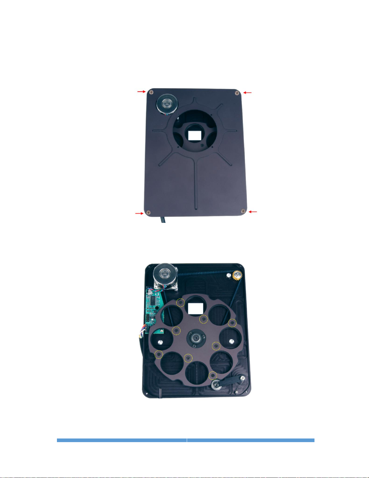
4. Place the filter wheel on a clean dry surface with the camera side facing
down. Orient it so that the motor is at the top left corner.
5. Remove the four 4-40 cap screws that secure the filter wheel’s front
plate (FW8S shown) and lift it off the base plate.
Set the front plate aside.
6. Separate the filter retainer from the carousel by removing the eight
Philips screws (circled) that attach the filter retainer to the carousel.
Set the filter retainer aside. Note that the filter retainer is the same size
and shape as the carousel and simply attaches to the carousel over the
filters to hold them in place.
ALUMA USER’S MANUAL
11
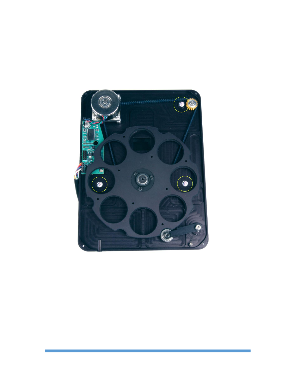
7. Carefully place the filter wheel bottom plate over top of the camera.
Ensure that the connector side is facing in the same direction as the
camera connectors.
The filter wheel motor shaft will be located within the notched corner of
the camera’s top circuit board. Carefully align the two and gently press
together. The filter wheel bottom plate should fit snugly and flush
against the front of the camera.
8. Reinstall the remaining three screws (circled) through the bottom plate
of the filter wheel.
9. Double-check that all pieces are properly seated and tighten the
screws.
10. Determine the location you want for each filter. The carousel slots are
numbered 1 to 8. You can later configure the MaxIm LT application to
correspond to your chosen filter order.
11. The filter wheel supports eight 36 mm filters (or 1-1/4" filters with
adapter rings). Ensure that your filters are clean prior to installation.

ALUMA USER’S MANUAL
12
12. If you are using filters that are 3 mm thick, then put one of the
supplied O-rings into the filter slot before placing the filter into the slot.
If the filters are less than 3 mm thick (e.g., Baader), then place the filter
into the slot first, followed by the O-ring. For filters over 3 mm thick, do
not use the O-rings.
13. Replace the filter retainer plate over the filters and fasten it to the
carousel using the eight Philips screws and washers that you removed
in step 6.
14. Replace the filter wheel front plate being careful not to pinch any wires
or the I2C cable.
15. Fasten the front plate to the base plate using the four 4-40 cap screws
that you removed in step 5.
16. Mount the camera and filter wheel assembly to your optical device. You
can use the supplied 2” nosepiece or other proprietary adapter for this,
as required.
17. Attach the cabling:
CAUTION:
Never “hot plug” the cables into or from the units. Always disconnect
power before connecting or disconnecting any cables.

ALUMA USER’S MANUAL
13
• The ALUMA filter wheel has a short cable extending from it with a
Mini-DIN connector. Plug this connector into either of the
I2C/FW/AO sockets on the camera. This cable is the same for both
the standard and self-guiding filter wheels and supplies power and
control signals to the filter wheel.
• If you have the FW8G-ALUMA Self-Guiding Filter Wheel, also attach
the supplied HDMI cable between the HDMI port on the self-guiding
filter wheel cover and the GUIDE HEAD port on the camera.
• If you are using an AO-8A Adaptive Optics unit, plug this into the
remaining I2C/FW/AO socket on the camera.
• TIC RJ11-RJ11 cable
This cable is only required for auto-guiding purposes in astronomical
imaging. It plugs into the GUIDE OUT connector on the ALUMA
camera and connects to the guide port on a telescope mount.
• Attach the USB cable between the USB connector and your
computer. This is only required for non-wireless camera operations.
• Install the ferrite clamp in a convenient position along the camera
power cable, preferably close to the camera, then plug the cable into
the POWER connector.
The camera is now ready to be powered up.
1.4 Applying Power
1. Connect the cable between the power supply and the camera.
2. Plug in the power supply to turn it on.
NOTE:
The ALUMA camera comes with a power supply capable of operating from
90 to 264 VAC, and supplies 80W maximum. Actual power requirements
are +12 VDC at 5A.
The camera may also be powered directly from a capable +12 VDC source
using an appropriate cable (not supplied). Refer to the power jack pinout
diagram in Appendix A-3 to source or create such a cable.

ALUMA USER’S MANUAL
14
1.5 Testing the Camera and Filter Wheel
Once the camera hardware has been assembled and MaxIm LT is installed and
configured, Diffraction Limited recommends that you conduct a simple bench
test of the system to verify the functionality of all components.
You should review Chapter 2 - Operating ALUMA with MaxIm LT to familiarize
yourself with the basic software connection and operating instructions prior to
performing this test.
Proceed with the bench test as follows:
1. Verify that all cabling is properly connected.
2. Apply power to the camera.
3. Open MaxIm LT and connect to the camera (refer to Section 2.1).
4. Set the camera cooler to ON.
NOTE:
Operating the camera at very high ambient temperatures (in excess of
+40 degrees C) or within a sealed enclosure can lead to overheating.
Under these conditions, it is possible that the heat generated by the
camera cooler could heat the camera body to the point that the
electronics might malfunction. To prevent that, overheating protection
has been implemented in the camera firmware. If the camera’s internal
temperature rises above +75 degrees C, the camera will turn off the
cooler completely. No warning of this is provided. However, since the
sensor temperature is recorded in the FITS header, you will be able to
determine if the cooler stopped working for a particular image.
5. Take a set of exposures including both dark and light frames. Set your
exposure length to a very short duration to avoid saturation if you are
conducting this bench test under bright lighting conditions.
Alternatively, you can limit the light entering the camera by covering the
sensor opening using a piece of cardboard with only a pinhole opening
in it.
6. If you are using a filter wheel, also take a set of light exposures using
each of the available filters to ensure proper operation of the wheel.

ALUMA USER’S MANUAL
15
2 - Operating ALUMA hardware with MaxIm LT
The MaxIm LT application allows full configuration and control of the ALUMA
cameras and filter wheels as well as Diffraction Limited adaptive optics units.
Calibrating files, automating imaging sequences, logging, and various image
processing tasks can all be performed. Please note however that since MaxIm
LT and MaxIm DL both share the same Help file, not all features detailed in
that file will be enabled in MaxIm LT. Full feature access requires MaxIm DL
Pro.
The procedures in this chapter are intended as a basic introduction to
connecting and operating the ALUMA hardware. Consult the Help file for
further information on specific parameters, detailed procedures, and various
tutorials.
2.1 Connecting the ALUMA Camera to MaxIm LT
The following is the basic MaxIm LT procedure used to configure and connect
to the ALUMA camera and an optional filter wheel.
1. Launch the MaxIm LT application.
2. Click the Camera Control icon or press Ctrl-W to open the Camera Control
window and click the Setup tab.
3. Click the Setup Camera button under Camera 1. The Setup DL Imaging
form opens.
4. Click the Camera Model drop-down. Three choices are available:
Simulator, DL Imaging, and SBIG Universal. Select DL Imaging.
5. Configure the IP Address parameter on the form, if required.
6. Click the Advanced button. The DL Config form opens. This form allows
you to check camera parameters and also to perform firmware updates
and additional camera configuration.
7. Select your camera from the Devices list. Various camera parameters will
auto-populate the display fields in the form. Also note that the next time
you open MaxIm LT, your serial number will appear in the Camera
dropdown in the Setup DL Imaging form.
8. Click the Settings button. The DL :: Settings form opens to allow access to
additional camera settings. Configure as required and click OK to accept
the settings and close the form.
9. Click OK to accept the settings in the DL Config form and close it Your
preferences will also be saved.
10. Click OK to accept the settings and close the Setup form.
11. Click the Options button under Camera 1. The Options form opens.
12. Configure any of the optional camera parameters if required or use the
default values as a starting point.

ALUMA USER’S MANUAL
16
13. Click OK to accept the settings. The Options form closes.
14. Click the Setup Filter button under Camera 1 if you are using an ALUMA
filter wheel controlled by MaxIm LT. The Setup Filter form opens.
Otherwise, go to step 15.
NOTE:
Controlling filter wheels from other manufacturers requires a fully-featured
application such as MaxIm DL Pro or other supportive software.
15. Select DL Imaging+FW from the drop-down menu.
NOTE:
You can edit a filter’s name in this form by double-clicking the existing
name in the list.
16. Configure any other parameters that appear on the form or use the default
values as a starting point.
17. Click OK to accept the settings. The Setup Filter form closes.
18. The settings under Camera 2 are used to connect to a second separate
camera for guiding purposes.
NOTE:
If you are using the self-guiding FW8G-ALUMA filter wheel (for
astronomical imaging), you must select the Dual Chip Mode for Camera 1
instead. Camera 2 is not used for this purpose.
Repeat steps 3 to 17 if required for Camera 2.
19. Click the Connect button to establish camera communications.
20. Enable the camera cooler(s) by clicking the On button.
21. Click the Cooler button under Camera 1. The Set Camera Cooler form
opens.
22. Set the desired cooler temperature (in degrees Celsius) and click OK. The
Set Camera Cooler form closes.
23. Click the Cooler button under Camera 2, if applicable. The Set Autoguider
Cooler form opens.
24. Set the desired cooler temperature (in degrees Celsius) and click OK. The
Set Autoguider Cooler form closes.
The ALUMA camera and filter wheel are now connected and ready to begin
imaging.
NOTE:
When attaching the ALUMA camera to your operational equipment such as a
telescope, consider looping the USB and power cables around the camera
handle to provide strain relief. Cable tie wraps can also be used for this
purpose.

ALUMA USER’S MANUAL
17
2.2 Basic Imaging Procedure
After setting up the ALUMA camera and filter wheel as stated above, the
Expose tab in the Camera Control window allows you to set the exposure
parameters and initiate imaging. This procedure details the basic approach to
imaging with the ALUMA camera.
1. Click the Expose tab.
2. Configure the parameters as follows:
• Click on the Camera 1 radio button.
• Exposure Preset: The presets allow you to quickly configure the
exposure parameters for different types of imaging. Use the Standard
exposures option for this introductory imaging procedure.
• Readout Mode: Normal
• Frame Type: Light
• Filter Wheel: Luminance
You can only set this parameter if you configured a filter wheel for the
camera. A Luminance filter allows full visible spectrum illumination of
the sensor, but you can select another filter type if you wish. If one of
your filter slots is empty, you can also use that instead.
• X Binning: 1
When binning greater than 1 is selected, the electronic charge from
groups of adjacent 2x2 or 3x3 pixels is electronically summed in the
camera before readout. This process adds no noise and effectively
increases sensitivity at the cost of lower spatial resolution. Binning of
the X and Y axis of the sensor can be configured individually.
• Y Binning: Same or 1
• Subframe: Deselect the On checkbox. This will ensure that you capture
the entire frame, rather than just a part of it.
• Seconds: Set the desired exposure time in seconds. You can use the
scroll arrows or type in a value into the field. Exposures of less than a
second must be entered as decimal values.
3. Click the Options arrow. A fly-out menu is displayed. This is used to
access and configure a number of imaging parameters to customize your
imaging requirements.
For this introductory imaging procedure, set the following:
• Click on No Calibration.
• Click on Set Image Save Path. The Select Folder form opens. Use this to
specify where to save your images.
• Click on Exposure Delay. Use this if you want to set a delay time (in
seconds) prior to beginning an exposure. If you are taking a continuous
sequence, this delay will be applied between each image.
• Click on Show Tool Tips if you want to display pop-up tips on form
options.

ALUMA USER’S MANUAL
18
4. To begin an individual exposure, click the Single radio button and then the
Start button. You can end the exposure manually at any time by pressing
Stop. You must save this image manually if you want to keep it.
5. To begin a continuous sequence of identical exposures, click the
Continuous radio button and then the Start button. The sequence only
ends when you press Stop. This mode is generally used for focusing and
framing purposes, and acquired images are not saved.
6. To configure a custom sequence of exposures, click the Autosave button.
The Autosave Setup form opens.
For this introductory imaging procedure, set the following:
• Autosave Filename: Enter the base filename (e.g. “M27”) you want to
use for the sequence of images. Each image file taken will use this
name, appended with an individual frame number, for example, "M27-
001.fit".
• Dither: Off
• Delay First: Specify a delay time (in seconds) prior to taking the first
exposure, if desired.
• Delay Between: Specify a delay time (in seconds) between exposures, if
desired.
• Click the Slot 1 button and configure each of the parameters on the
line as you require. The Repeat parameter allows you specify how many
of these particular exposures will be taken. An optional Suffix can also
be automatically applied to the end of the filename to aid you in
identifying the image later on. For example, if you configured a Red
filter slot, you might want to add a Suffix of "R". This will produce a
filename such as "M27-001R.fit". If you use only one imaging slot then
you don’t really need a suffix. However, if you set up multiple slots and
want to add a suffix, then each suffix must be unique. You can
configure up to 32 slots when setting up an Autosave sequence.
• Click OK when you are finished configuring the sequence.
7. To begin the custom sequence, ensure that the Autosave radio button is
selected and click Start. You can end the Autosave sequence at any time
prior to its completion by pressing Stop.

ALUMA USER’S MANUAL
19
3 - Image Calibration
Image calibration, also known as image reduction or pre-processing, applies
corrections for tiny defects and variations in the camera sensor and optical
system. Proper image calibration is of the utmost importance in producing the
highest-quality images possible.
No electronic imaging device is perfect. Each sensor has a unique response in
the following three areas:
• Bias level
• Dark current
• Raw sensitivity to light levels
These effects don’t just vary from sensor to sensor, they also vary from pixel to
pixel within the same sensor. Each response affects the intensity represented
in every pixel of the image in a specific way. The combined effect of these pixel
variations may be relatively small on brightly-lit images, but under low-light
conditions, they can become extremely important.
The majority of the problems caused by these variations can be readily
removed by calibrating the raw image. Performing basic image calibrations can
provide a huge improvement in the signal-to-noise ratio, resulting in much
greater sensitivity. Nominalizing these variations also provides a truer
representation of the subject in the working image. This provides the best
possible basis for any subsequent image processing.
The basic calibration steps are termed Bias, Dark, and Flat-Field calibration.
These are detailed below. A general workflow is then provided for image
calibration and the subsequent combining of multiple light frames, if required.
Refer to the online Help file for further information and more detailed
procedures, as required.

ALUMA USER’S MANUAL
20
3.1 Bias Frame Calibration
Bias is an offset that occurs when a pixel is read from the camera.
Unfortunately, bias can vary across the image. Also, if bias is not corrected,
then flat-field calibration will not work correctly.
A bias frame is essentially an exposure with a duration of zero (or in reality, as
close as possible to zero length) and taken with the shutter closed. Each pixel
will have a slightly different value, but except for a small amount of noise, the
value for any one pixel will be consistent from image to image. Since the bias is
consistent from image to image, it can be subtracted.
The bias frame itself contains a small amount of readout noise. This readout
noise is produced inside the electronics that read the pixels. It can be very low
in sophisticated cameras, but it is never zero. This noise can be easily
suppressed by combining a number of bias frames together.
Ideally, the other types of calibration frames should also be bias-frame
calibrated. MaxIm LT does this automatically when bias frame files are
selected.
The bias for a particular camera is generally constant over a substantial period
of time. This means that you can take bias frames just once, and use them on
all your images for many months to come. Note that some cameras may have a
small bias dependency on temperature. Small bias offsets are not important of
themselves, but they can degrade the effectiveness of flat-fielding calibration.
It should be mentioned that bias is also included in dark frames. As such, it
actually is possible to perform accurate calibration without using bias frames.
That said, you should always use bias frames if either of the following are true:
• You are using exposure scaling to match dark frames to light frames
• You are using flat-field frames but are not using matching dark frames
("flat-darks")
Bias frames are extremely easy to acquire, so there is little reason to skip
them. You can quickly acquire 10 or 20 frames to average, so the read noise in
the bias frames will not be contributing to your overall noise level.
Taking Bias frames
1. Connect to the camera (as per section 2.1) and click the Expose tab.
2. Configure the tab’s parameters as follows:
• Click on the Camera 1 radio button.
• Exposure Preset: irrelevant
• Subframe: Deselect the On checkbox. MaxIm DL will extract the
appropriate subframe from the calibration full frame if required.
3. Click the Options arrow and set the following:
• Click on No Calibration.
• Click on Set Image Save Path and specify the file location.

ALUMA USER’S MANUAL
21
4. Click the Autosave radio button to configure a sequence of 10 to 20
identical exposures. You only need to configure one slot with the required
parameters:
• Type: Bias
• Filter: irrelevant
• Exposure: Set to the shortest possible value for your camera
• Binning: Set to same as your Light frames
• Readout Mode: Normal
• Repeat: Set to the number of exposures you want
Click OK when done.
5. Click the Start button to begin the sequence.
When the sequence completes, you will have a set of bias frames that can
subsequently be used to create a calibration group and apply a bias calibration
to your light frames.

ALUMA USER’S MANUAL
22
3.2 Dark Frame Calibration
Every camera sensor produces a certain amount of dark current, which
accumulates in the pixels during an exposure. The dark current is produced
by heat, and high-performance cameras cool their sensors to minimize this
effect.
The main problem with dark current is that it accumulates at a different rate
in every pixel. Some pixels are "hot" and others are "cold". Unfortunately there
is usually a spattering of pixels that are especially hot, which degrade the
image a great deal. Fortunately, the effect of hot and cold pixels can be easily
removed by subtracting a dark frame.
A dark frame is an exposure taken under the same conditions as the light
exposure, but with no light striking the sensor array. Since each pixel is
consistent in its dark current at any one temperature, the dark frame can be
subtracted from the light frame to remove the fixed pattern from the image. For
most sensors this produces a striking improvement in the image.
Unfortunately, while the rate of dark current is constant, the actual
accumulation of dark current is random. Anything that is random in imaging
is noise, which is the enemy of sensitivity. Doubling the dark current increases
the random noise produced by the square root of 2 (approximately 1.414). This
means the hot pixels produce significantly more noise. Since the noise is
random and therefore unpredictable, it cannot be removed; in some calibrated
images they will be brighter than normal, and in others they will be darker
than normal. You can improve the hot pixels, but you cannot completely fix
them.
So subtracting a dark frame eliminates noise because it gets rid of the gross
pixel-to-pixel variations in dark current. Unfortunately, and perhaps
counterintuitively, subtracting a dark frame also adds noise to the image.
Every pixel has random read noise, plus the residual dark current noise. This
noise does not subtract, but rather adds in a root-sum-square fashion.
Therefore simply subtracting one dark frame increases the noise level 41%.
The way to get rid of this noise is to remove it by averaging multiple dark
frames. Every time you quadruple the number of averaged dark frames, you
drop the noise contribution in half.
Suppressing Hot Pixels
Although you can greatly improve the hot pixels by calibration, there will still
be a residual speckle of hot and cold pixels in the image. For astronomical
applications, you can “dither” the pointing of the camera slightly between
exposures, thus distributing the noise contribution of each hot pixel to a
slightly different position on the image. You can then combine a number of
images together using the Median, Sigma Clip, or SD Mask algorithm, which
will reject the hot pixel contributions altogether.

ALUMA USER’S MANUAL
23
Dark Frame Scaling
The longer the exposure you take, the more dark current accumulates. This
means that the dark frame and light frame must have the same exposure time
in order for calibration to work. They must also be taken at exactly the same
temperature as nearly as possible, because the rate of dark current
accumulation varies strongly with temperature. The TE coolers in the camera
allow high precision temperature regulation which greatly simplifies
management of the dark frames.
If a dark calibration frame that precisely matches the exposure duration
and/or temperature of an image is not available, you can employ Dark Frame
Scaling as an alternative. Use a dark frame whose temperature and exposure
duration are as close to those of your light frames as possible, and configure
the Set Calibration command to perform scaling. Using a bias frame is strongly
recommended in this situation (bias is constant and does not scale with
exposure time).
There are two types of automatic scaling available: Auto Scale and Auto
Optimize. Auto Scale will adjust the scaling based on the exposure times listed
in the FITS header. This is useful for situations where the exposure time
changes, but the temperature does not. If exposure time information is not
available, or the images were taken at different temperatures, the Auto
Optimize algorithm will perform an iterative adjustment of the scaling until the
noise is minimized.
With a temperature-regulated camera, you can create a library of “master
frames” by shooting sets at various temperature settings and exposure lengths.
These can then be used to calibrate any matching exposure taken with the
same camera. Dark Frame Scaling can then be used if an exact match is not
available. If you enter multiple sets of calibration frames into Set Calibration,
MaxIm LT will automatically choose the frames that best match the exposure
conditions.
Some users just take a single set of long dark frame exposures and use the
exposure compensation feature for shorter light exposures. Most cameras are
highly linear, so this technique works very well.
Taking Dark frames
1. Connect to the camera (as per section 2.1) and click the Expose tab.
2. Configure the tab’s parameters as follows:
• Click on the Camera 1 radio button.
• Exposure Preset: irrelevant
• Subframe: Set to same as your Light frames
3. Click the Options arrow and set the following:
• Click on No Calibration.
• Click on Set Image Save Path and specify the file location.

ALUMA USER’S MANUAL
24
4. Click the Autosave radio button to configure a sequence of 10 to 20
identical exposures. You only need to configure one slot with the required
parameters:
• Type: Dark
• Filter: irrelevant
• Exposure: Set to the same length as your Light frames
• Binning: Set to same as your Light frames
• Readout Mode: Normal
• Repeat: Set to the number of exposures you want
Click OK when done.
5. Click the Start button to begin the sequence.
When the sequence completes, you will have a set of dark frames that can
subsequently be used to create a calibration group and apply a dark
calibration to your light frames.

ALUMA USER’S MANUAL
25
3.3 Flat-Field Frame Calibration
Each pixel in the camera has a slightly different sensitivity to light. These
sensitivity differences add another noise component to the image (known as
flat-fielding error) unless steps are taken to compensate. While flat-fielding
correction is important for achieving high quality images, it is absolutely
essential for accurate photometric measurements.
Pixel-to-pixel variations in light sensitivity are imprinted into an image, with
the more sensitive pixels showing up as brighter dots. When long exposures
are used to image extremely faint subjects, such as in astronomical
applications, the ultimate sensitivity limit is determined by how precisely the
flat-fielding error can be removed.
There are several common sources of flat-fielding variations. Typical sensors
have pixel-to-pixel variations on the order of 1%. Vignetting in the optical
system can reduce the light flux at the corners of the sensor. Dust on optical
surfaces near the sensor can cast shadows (often called “dust donuts” due to
their appearance in centrally-obstructed optical systems). Compressed air can
help reduce dust donuts, but it is often difficult to completely eliminate them.
To create a flat-field frame, the optical system must be illuminated by a
uniform light source and an exposure is taken. To avoid non-linearity at the
top and noise at the bottom of the camera's range, the exposure is usually
chosen to get an average value of 30% to 50% of the saturation level. The flatfield is then renormalized by dividing each pixel into the average value in the
array. Any pixel that is more sensitive is assigned a number slightly below 1
and any pixel that is less sensitive is assigned a number slightly above 1.
When this frame is multiplied by a raw image, it removes the sensitivity
variations.
Methods for acquiring Flat-Fields
Flat-fielding is by far the most troublesome calibration method. The entire
aperture of the optical system must be evenly illuminated with light – if this is
not done very carefully, then the flat-field will be wrong. Light leaks will ruin
the calibration by adding unfocussed light that did not pass through the
optical system. In addition, once calibrated, the camera cannot be moved or
even refocused. Finally, some sensors have significant flat-field variation as a
function of wavelength (color), and it can be difficult to create a reasonable
facsimile of the normal illumination spectrum.
Given these problems, a good flat-field can be very difficult to achieve for
certain types of optical equipment, and so this calibration step is sometimes
skipped. However, if there is no vignetting and dust donuts are not an issue,
calibrating the camera alone may be sufficient. Cover the end of a roughly sixinch long opaque tube with a translucent material (a few layers of white
photocopy paper will do in a pinch). Place this over the front of the camera,
gently illuminate the assembly with white light (natural or incandescent, not
fluorescent or LED), and take an exposure with a duration that produces a
brightness level of roughly 30% of full scale. The resulting images can be used
to flat-field the camera, regardless of the optics used. Note that the camera’s
window must be very clean (that is, no dust spots) for this to work properly.

ALUMA USER’S MANUAL
26
The flat-field frames themselves must be calibrated to remove bias, and for
longer exposures, dark frame correction must also be performed. It is essential
that both the flat-field frames and light frames are properly bias corrected,
otherwise the flat-field operation will not work correctly (mathematically,
subtraction and division are not commutative).
The calibration tools in MaxIm LT handle the mechanics of bias correction and
renormalization automatically.
Taking Flat-Field frames
1. Configure your optical system to acquire flat-fields, as suggested above.
2. Connect to the camera (as per section 2.1) and click the Expose tab.
3. Configure the tab’s parameters as follows:
• Click on the Camera 1 radio button.
• Exposure Preset: irrelevant
• Subframe: Set to same as your Light frames
4. Click the Options arrow and set the following:
• Click on Full Calibration. When you configure your calibration schema,
include Bias frames and if required, dark frames as well.
• Click on Set Image Save Path and specify the file location.
5. Click the Autosave radio button to configure a sequence of 10 to 20
identical exposures for each filter you used in your light exposures.
Configure one slot per filter with the required parameters and number of
repeat exposures you want. Click OK when done.
• Type: Flat
• Filter: This must be set to use the same filter as your light exposures.
So if you are performing tri-color or narrowband imaging, you must take
a set of flat-field images for each filter used.
• Exposure: Set this to produce an image with 30% to 50% of the
saturation level
• Binning: Set to same as your Light frames
• Readout Mode: Normal
• Repeat: Set to the number of exposures you want
Click OK when done.
6. Click the Start button to begin the sequence.
When the sequence completes, you will have a set of flat-field frames that can
subsequently be used to create a calibration group and apply a flat-field
calibration to your light frames.

ALUMA USER’S MANUAL
27
3.4 Understanding Calibration Groups
MaxIm LT allows you to set up the calibration frames into multiple groups of
files to provide a high level of calibration automation and flexibility, including:
• Automatic creation of master calibration frame libraries
• Fully-automatic calibration of images sequences involving different
exposures, filters, and binning
• Autoguider per-filter exposure scaling without needing new dark frames
• Eliminating the need to shoot autoguider dark frames during a session
• Automatic selection of flat-darks
As previously discussed, calibration requires bias, dark, and flat files. In
practice, users can often take exposures with different settings in a single
imaging session. Individual exposures may vary by exposure time, sensor
temperature, binning, filter band, subframing, and different cameras may even
be in use (e.g. an autoguider versus the main camera).
MaxIm LT can perform exposure scaling to account for exposure duration
(Auto Scale) and to some extent temperature (Auto Optimize). The software can
also automatically extract a subframe from the calibration frames. But
differences in binning, exposure bands, filters, and of course cameras cannot
be accommodated except by using multiple calibration frames. Switching back
and forth manually can be time consuming, particularly if complex exposure
sequences are taken with different filters and binning, as is typically done for
LRGB imaging and photometry.
A Calibration Group is simply a set of one or more calibration frames that are
taken under the same conditions. For instance, a set of 10 dark frames taken
at -20C with a specific camera would be one group. A set of flat frames taken
with a green filter would be another.
These groups can be automatically generated by scanning a folder or folder
tree. All image files with matching characteristics are grouped together, based
on the information in their FITS headers. Alternatively, the user can choose to
manually create calibration groups.
All the files in a group are combined using an average, median, sigma combine,
or SD Mask algorithm to make an internal "master frame" that is used to
calibrate images. This master frame is not visible to the user.
However, some users prefer to generate and save the master calibration frames
so they can be quickly reloaded and used at a later date. The Set Calibration
command allows you to do this. Note however that this step is completely
optional and is not required for the calibration process to work properly.
When master calibration frames are generated and saved to disk, the list of
groups in the Set Calibration window is automatically replaced by these master
frame files. If bias subtraction is enabled and suitable groups are available, the
darks and flat masters will automatically be bias-subtracted. Similarly, the flat
masters will be dark-subtracted if dark subtraction is enabled and suitable
groups are available.

ALUMA USER’S MANUAL
28
When the masters are saved to disk, they are tagged with header flags to
indicate whether these subtractions have been done. In that way when they
are loaded again later, MaxIm LT will know whether they need to have these
subtractions performed or not.
3.5 Calibrating and Combining Images
While calibration reduces or removes the majority of the problems caused by
bias, dark current, and light sensitivity variations in a camera sensor, there is
still random noise remaining in the actual scene that the sensor records. If a
pixel receives 100 photons of light from a target, there will be 10 photons of
quantum photon noise due to the statistical nature of light. Some additional
noise will be present due to camera read noise and dark current noise.
The key thing to note here is that this noise is random in nature and varies
from frame to frame, whereas the object of interest, such as a distant galaxy,
generally does not. By combining numerous individual frames of the same
subject, the subject’s signal steadily increases in a linear fashion. However,
since the noise in a single image is random, its increase in a combined image
follows a Poisson statistical distribution and so it increases more slowly.
Combining images therefore increases the overall signal-to-noise ratio in the
final result, yielding both smoother subject and background appearances.
Combining files (also known as “stacking”) is not limited to your light frames,
but is also applicable to your calibration frames, since all imaging frames
include noise.
When you add or subtract images, the noise is always additive. Subtracting a
single dark frame from a light frame will remove large pixel-to-pixel variations
in the average accumulation of dark current, but it will also increase the
random noise in the light frame by 41%. If instead you averaged sixteen dark
frames together prior to subtraction, the noise will only be increased by 10%.
The standard combine method is to Average the frames. This produces the best
results for purely random Gaussian noise. Unfortunately if there is an “outlier”
pixel on one frame (e.g., a cosmic ray hit) then it will be included in the
average.
Median combine is much more effective at suppressing outlier pixels.
Unfortunately, median combining increases the noise level 25% compared to
averaging. When median combining flat-field frames, renormalization is also
required. This ensures that each frame is at the same average brightness.
MaxIm LT does this automatically.
An alternative to Median combine is to use Sigma Clipping or Standard
Deviation Masking. These techniques throw out outlier pixels and then average
the remaining. They are in effect a compromise between median and average,
combining the noise reduction advantages of Average with the outlier pixel
rejection of Median combine. You can also select renormalization options for
these methods.

ALUMA USER’S MANUAL
29
General workflow for calibrating and combining images
The following is a general summary of the basic workflow used in MaxIm LT to
calibrate and combine images. As such, consider it an overview. Numerous
parameters not cited here are available to tailor the process to specific imaging
types and requirements. Refer to the MaxIm DL Help file for full tutorials,
further information, and more detailed procedures, as required.
Under Automatically Generate Groups click the Folder button to browse to a
folder containing your calibration images.
1. Use the Set Calibration command to set up calibration groups that will be
used to calibrate your individual raw light frames. Proceed as follows:
a) Click Process > Set Calibration. The Set Calibration form opens.
b) Click the Folder button in the Automatically Generate Groups section to
browse to the folder containing your calibration images.
c) Select Auto-Generate (Clear Old) using the Auto-Generate dropdown
button. A set of Calibration Groups will appear in the list, with images
pre-sorted by calibration type, exposure, sensor temperature, etc.
d) To adjust the settings for an individual group, click on the group to
highlight it. You can then set the parameters such as Dark Frame
Scaling and Combine Type in the Group Properties section as desired.
You can also change the Name of a group by double-clicking it in the
list.
e) If you want to create a master calibration file for this group of files, click
the Replace w/ Masters button. MaxIm LT will combine the files and
display the master file name in the Group Membership field. The master
file will automatically be saved in the same folder that contains the
individual calibration files. If you choose not to create such master
calibration files, MaxIm LT will stack the calibration frames on-the-fly
when you calibrate your light frames.
f) Click OK when you are done.
2. Use the Stack command to calibrate and combine your raw light frames.
Proceed as follows:
a) Click Process > Stack. The Stack form opens.
b) On the Select tab, turn on Classify by FILTER if your images were
acquired using filters and then click the FILTER button to set up the
filter mapping. This will determine what filters are mapped into which
LRGB color channels. To change a row, click once on the row, then click
once on the Filter Color(s) item, and enter a new value. This will make
sure that your filters are automatically assigned to the correct group.
c) Enable the Mark added images as Auto Calibrate checkbox. Each image
will automatically be calibrated as it is needed, using the settings from
the Set Calibration command.

ALUMA USER’S MANUAL
30
d) Click the Add Files button to select the desired files. You can also use
the drop list adjacent to the Add Files button to select entire folders of
files to add. Browse to the folder where your images are located. When
you add individual files or folders, they will appear in the Groups tree at
left. You can also deselect individual files from the tree so that they will
not be included in the stacking process.
e) Configure the parameters in the Stack form’s remaining tabs as
required:
• Select the Quality tab to configure parameters that limit which files
will be stacked, based on various quality criteria.
• Select the Align tab to enable precise alignment of images. This is
particularly useful in astronomical imaging, where a certain amount
of shift from image to image is usually present.
• Select the Color tab to customize the color balance settings if
desired. Otherwise click the Defaults button, which assumes 1:1:1
color balance.
The parameters contained in these tabs are explained in detail in the
Help file. Refer to the Image Processing – Stacking tutorial.
f) Select the Combine tab and set the Combine Method. For large
numbers of images, try using Sigma Clip - a Sigma Factor of 3 is a good
starting point. If you have a modest number of images, the SD Mask
mode will produce a better result but will take more time - a good
starting point is a Sigma Factor of 0.5 and Number of Passes set to 3.
The remaining Combine parameters and options are detailed in the Help
file. Set these as required.
g) Click Go to start the stacking process. This may take some time, so you
can interrupt and restart the process if needed. If you have multiple
image groups, they will be stacked separately. Color sets will
automatically be color combined.
When the combining process completes, the final product is a calibrated
master light frame that can be used as a basis for any further image
processing.
You can save this image in a number of different formats. The FITS (Flexible
Image Transport System) file is the standard file format used in astronomical
applications. It includes extensive support for header information to describe
the image, along with the equipment and procedures used to produce it.
For other applications, we recommend using 16-bit TIFF images. If you are
using the supplied MaxIm LT software, the choice of TIFF or FITS can be set
under: File menu > Settings > Files tab > Default File Extensions
Setting this will determine the default file type created when MaxIm LT takes
images.
ALUMA USER’S MANUAL
31
4 - Accessories
4.1 ALUMA Micron-Precision Filter Wheel
The optional FW8S-ALUMA 8-position filter wheel includes a positive centering
mechanism that precisely centers each filter in the exact same position every
time. This single-pixel accuracy completely eliminates ghost images of dust
spots and other artifacts after flat-fielding.
Positive detent mechanism provides single-pixel filter position accuracy
Precision flat-fielding with ultra-accurate indexing
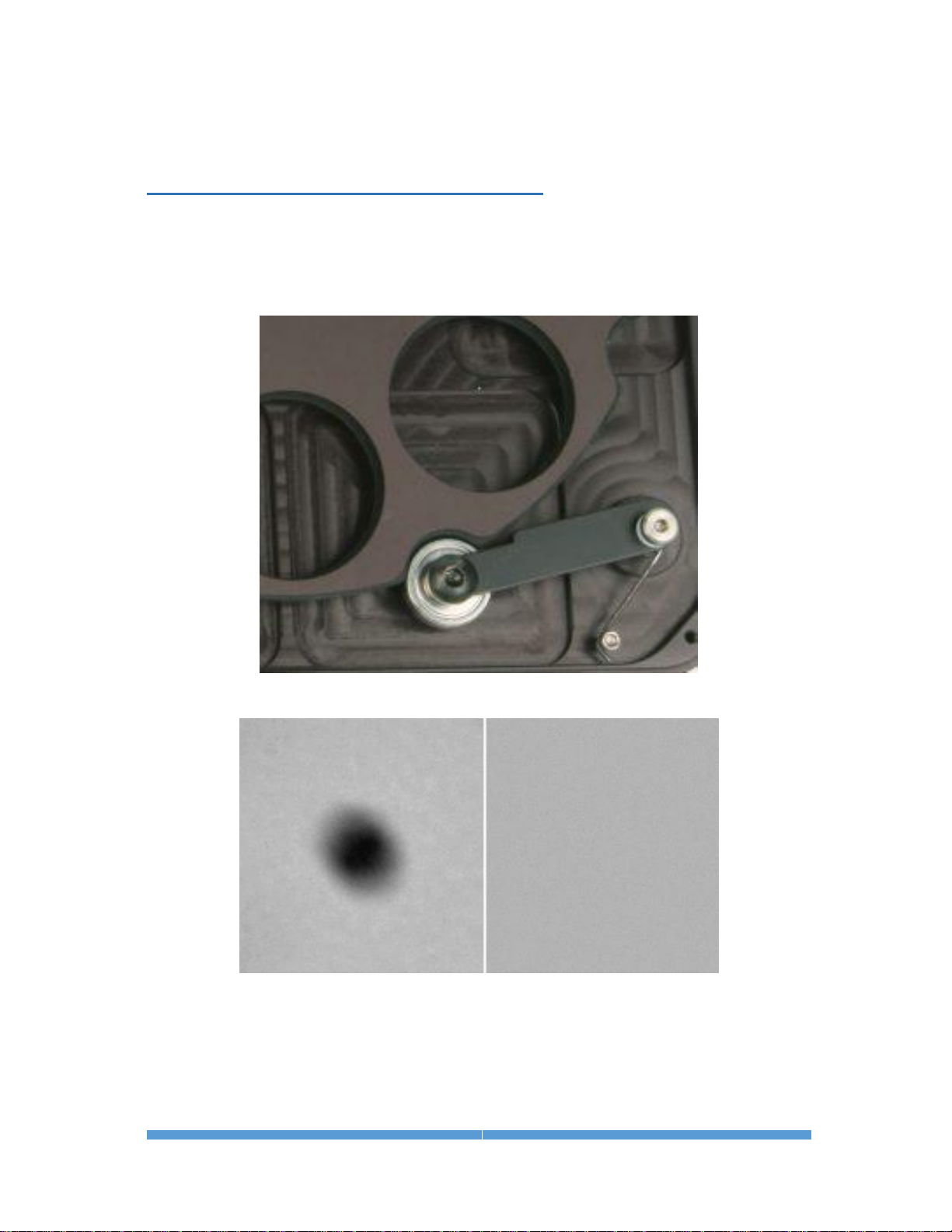
The left-hand image shows a dust spot on the filters. A flat-field calibration
frame was taken, then the filter wheel was rotated several times before taking a
second picture, which was flat-field calibrated, at right. No evidence of the dust
spot is visible. This high precision results in the highest quality images and
excellent photometric accuracy.

ALUMA USER’S MANUAL
32
The ALUMA wheel holds standard 36 mm filters, and inserts are available for
1-1/4″ filters, which are suitable for smaller format imaging sensors.
The ALUMA filter wheel replaces the camera’s front plate, resulting in the
minimum possible back-focus, ensuring that the camera / filter wheel
combination will reach focus on the widest possible variety of optical systems.
Integrated autoguider with adjustable pick-off mirror and focal reducer
For astronomical imaging, the wheel is also available in the FW8G-ALUMA selfguiding configuration. This adds a built-in focal reducer and autoguider. The
pick-off mirror and guide camera focus can both be adjusted and locked using
simple thumbscrews. With the autoguider positioned in front of the filters,
optimum guiding sensitivity is provided for all filter slots. Using a built-in
autoguider also system eliminates issues with flexure, mirror shift, and other
mechanical problems that can degrade guiding accuracy.
Note that the this version requires more back focus than the standard wheel.
Interchangeable front plates are available to switch your filter wheel between
the FW8G and FW8S configurations.
Refer to the Diffraction Limited website for details at:
http://diffractionlimited.com/products/cameras-accessories/filter-wheels/

ALUMA USER’S MANUAL
33
4.2 AO-8A Adaptive Optics
Diffraction Limited is the market leader in Adaptive Optics tip-tilt guiding
systems. Our adaptive optics units provide fast, precise positioning control
without the lag, backlash, stiction, and other problems associated with
telescope mounts. The AO units can reduce the impact of seeing, resulting in
tighter star images and higher resolution.
All ALUMA models can operate with the AO-8A Adaptive Optics accessory.
The AO-8A uses a tip-tilt window to quickly and precisely adjust the image
position in response to autoguider feedback. With Adaptive Optics there is no
backlash, stiction, or lag, and the movements are extremely precise and
accurate. This allows the AO-8A to not only remove the effects of periodic error,
drift, and wind gusts, but also reduce the effects of atmospheric seeing. The
AO-8A requires an off-axis guide camera behind the device. Diffraction Limited
recommends using the FW8G-ALUMA filter wheel. The AO-8A can also be
used with a Remote Guide Head if you have a custom Off-Axis Guider.
Refer to the Diffraction Limited website for details at:
http://diffractionlimited.com/product/ao-8a/

ALUMA USER’S MANUAL
34
4.3 Remote Guide Head for the ALUMA Series cameras
You can add a remote guiding camera head to your ALUMA camera to guide
your telescope using a separate guide scope, camera lens or OAG. The Remote
Guide Head (RGH) contains the same KAI-0340 monochrome CCD sensor that
is used in the self-guiding filter wheels for the ALUMA cameras. The RGH can
only be used when connected to the GUIDE HEAD port on an ALUMA, STT or
STXL camera. The RGH can also control an Adaptive Optics accessory.
Refer to the Diffraction Limited website for details at:
http://diffractionlimited.com/product/sttstxlstx-remote-guide-head/
4.4 Other Accessories
Numerous other accessories are available to enable a wide variety of user
configurations, including:
• Filters
• Mounting plates and nosepieces
• Adapter plates and inserts
• Tripod mounts
• Cables
• Power supplies
• and more …
Refer to the Diffraction Limited website for details at:
http://diffractionlimited.com/products/cameras-accessories/accessories/

ALUMA USER’S MANUAL
35
Appendix A: ALUMA Camera Details
A-1 Supplied components
• ALUMA main camera body (with handles and desiccant plug installed)
• Camera dust cap (10078)
• Power supply: 12V @ 6A Universal (60014A)
o Power cable with US plug (51089) (type specified on ordering)
o Power cable with European plug (50392) (type specified on ordering)
o Power extension cable (68007)
• Flash drive
• 2” Nosepiece adapter with cap (50146)
• Ferrite clip (51354)
• Relay cable RJ11-RJ11 (50711)
• USB A Male-to-Mini B 5 pin Male cable, 15 feet (68006)
A-2 LED Power indicator
The LED on the camera indicates the power input levels as follows:
• GREEN when the power input voltage is good, above 11.4V.
• AMBER when the power input voltage is low, dropping below 11.4V.
• RED when the voltage is very low, dropping below 10V. The lowest
possible voltage necessary to run the camera is 9V.
The LED turns off whenever exposures are in progress.
If you power up the camera with the USB cable not plugged in, the LED will
blink slowly (once per second) instead of glowing steadily. Normally, the
blinking indicates that the WiFi communication processor is booting up, and
then either establishing the Ad Hoc network or trying to connect to the WiFi
Access Point, depending on the camera WiFi settings. This normally requires
approximately 30 seconds. While the LED is blinking and the WiFi processor is
booting up, you cannot connect to the camera wirelessly.
When the LED stops blinking, the camera is ready. However, this does not
necessarily mean that the camera has successfully connected to the provided
WiFi network. If you cannot connect wirelessly, this likely indicates that the
WiFi network parameters you supplied are incorrect, such as the wrong SSID
or password.
The LED will also remain blinking whenever you power up the camera while an
external micro SD card has been plugged in to update the WiFi
communications processor firmware. This process takes approximately three
minutes, after which the LED will stop blinking. Do not unplug the camera
while this update is in progress.

ALUMA USER’S MANUAL
36
A-3 Connector pinouts
USB connector pinout is to USB standard.
GUIDE OUT (RJ-12), pins left to right:
Pin 1: AUX
Pin 2: COMMON
Pin 3: XPin 4: YPin 5: Y+
Pin 6: X+
Note: AUX is normally not connected
POWER connector (6-pin mini-DIN)
The diagram shows the pin number identification when looking into the
camera connector.
Pins 1, 3, 5: +12V
Pins 2, 4, 6: GND
GUIDE HEAD (HDMI style) connector is proprietary.

ALUMA USER’S MANUAL
37
I2C/FW/AO connectors (9-pin mini-DIN)
The diagram shows the pin number identification when looking into the
camera connector.
There are two of these, connected in parallel.
Pin 1: GND
Pin 6: 3.3V Out
Pin 2: I2C SDA
Pin 7: 12V Out
Pin 3: I2C SCL
Pin 8: Trigger Out 0
Pin 4: Trigger Out 1
Pin 9: Trigger In
Pin 5: N/C
NOTE: The Trigger In and Trigger Out functions are enabled via this connector.
The functions must be configured in the MaxIm LT application software when
you set up the camera.
CAUTION:
The Trigger In input voltage must not exceed 5.5V maximum.
Trigger In used to initiate exposures via an external control signal. The Trigger
In signal must be floating or connected to the camera's GND (or TTL Low Level)
before starting the Trigger Mode. If the signal is at the TTL High Level instead,
the exposure will begin as soon as Trigger Mode is started, just like a regular
(non-Trigger Mode) exposure. When Trigger In is properly configured, the
camera will periodically flush the CCD sensor while waiting for the TTL High
Level input signal on pin 9 of the connector. When you click Start to begin an
exposure, the camera will flush the CCD one last time and then start the
actual exposure, with a possible delay of up to 200 ms. Note that the Trigger In
signal can be switched back to the TTL Low Level at any point after the
beginning of the exposure.
The Trigger Out function can be used to control an external shutter, for
activities such as precision timing measurements or similar. For such
purposes, the same signal appears on Trigger Out 0 (pin 8) and Trigger Out 1
(pin 4), and the trigger output signal remains active during the exposure.
Note that Trigger Out is an open collector output, which means that it needs to
be pulled up to between 3.3 to 12V maximum (or requires an external pull-up
resistor) while the camera is inactive, and conversely, is active when low (at
GND) only during an exposure.

ALUMA USER’S MANUAL
38
A-4 Specifications
ALUMA 694
Imaging sensor
ICX-694
Peak QE
75%
Sensor size
14.6 mm x 12.8 mm
Imaging pixel array
2750 x 2200 pixels
Pixel size
4.54 μm (square)
Pixel digitization rate
8 MPix/sec
Total pixel count
6 million pixels
Full well capacity
18,000 e-
Read noise
4.5 e- typical
Dark current e/p/s at 0° C
0.025 e-/p/s typical
Anti-blooming
Yes
A/D converter
16-bit
Exposure duration minimum
0.001 sec
Full frame download
~1 sec via USB / ~6 sec via WiFi
Internal tracking sensor
No
Power
12 VDC, 5A max
Shutter
Mechanical, even-illumination
Temperature regulation
Yes
Cooling delta
Typical maximum -40° to -45° C
Dimensions
4.5″ x 4.5″ x 4″ (with handles)
Weight
2.2 lbs
Computer interface
USB2 and optional
WiFi 802.11 b/g/n
OS compatibility
Windows 32 and 64 bit,
Macintosh, Linux, iOS, Android
Supported options:
Adaptive optics
Yes
Filter wheel
Yes
Self-guiding filter wheel
Yes
Filter size
36 mm / 1.25″
Off-axis guiding
No
Remote guide head
Yes
USB-only / USB and WiFi
Aluma U694 / Aluma 694

ALUMA USER’S MANUAL
39
ALUMA 814
Imaging sensor
ICX-814
Peak QE
75%
Sensor size
12.48 mm x 9.98 mm
Imaging pixel array
3388 x 2712 pixels
Pixel size
3.69 μm (square)
Pixel digitization rate
8 MPix/sec
Total pixel count
9 million pixels
Full well capacity
15,000 e-
Read noise
4.5 e- typical
Dark current e/p/s at 0° C
0.025 e-/p/s typical
Anti-blooming
Yes
A/D converter
16-bit
Exposure duration minimum
0.001 sec
Full frame download
~1 sec via USB / ~8 sec via WiFi
Internal tracking sensor
No
Power
12 VDC, 5A max
Shutter
Mechanical, even-illumination
Temperature regulation
Yes
Cooling delta
Typical maximum -40° to -45° C
Dimensions
4.5″ x 4.5″ x 4″ (with handles)
Weight
2.2 lbs
Computer interface
USB2 and optional
WiFi 802.11 b/g/n
OS compatibility
Windows 32 and 64 bit,
Macintosh, Linux, iOS, Android
Supported options:
Adaptive optics
Yes
Filter wheel
Yes
Self-guiding filter wheel
Yes
Filter size
36 mm / 1.25″
Off-axis guiding
No
Remote guide head
Yes
USB-only / USB and WiFi
Aluma U814 / Aluma 814

ALUMA USER’S MANUAL
40
ALUMA 8300
Imaging sensor
KAF-8300
Peak QE
56%
Sensor size
17.96 mm x 13.52 mm
Imaging pixel array
3326 x 2504 pixels
Pixel size
5.4 μm (square)
Pixel digitization rate
10 MPix/sec
Total pixel count
8.3 million pixels
Full well capacity
25,000 e-
Read noise
10 e- typical
Dark current e/p/s at 0° C
0.15 e-/p/s typical
Anti-blooming
Yes
A/D converter
16-bit
Exposure duration minimum
0.1 sec
Full frame download
~1 sec via USB / ~7 sec via WiFi
Internal tracking sensor
No
Power
12 VDC, 5A max
Shutter
Mechanical, even-illumination
Temperature regulation
Yes
Cooling delta
Typical maximum -40° to -45° C
Dimensions
4.5″ x 4.5″ x 4″ (with handles)
Weight
2.2 lbs
Computer interface
USB2 and optional
WiFi 802.11 b/g/n
OS compatibility
Windows 32 and 64 bit,
Macintosh, Linux, iOS, Android
Supported options:
Adaptive optics
Yes
Filter wheel
Yes
Self-guiding filter wheel
Yes
Filter size
36 mm / 1.25″
Off-axis guiding
No
Remote guide head
Yes
USB-only / USB and WiFi
Aluma U8300 / Aluma 8300

ALUMA USER’S MANUAL
41
ALUMA 3200
Imaging sensor
KAF-3200
Peak QE
80%
Sensor size
14.85 mm x 10.26 mm
Imaging pixel array
2184 x 1472 pixels
Pixel size
6.8 μm (square)
Pixel digitization rate
4 or 1 MPix/sec (selectable)
Total pixel count
3.2 million pixels
Full well capacity
55,000 e-
Read noise
11.5 e- typical at 4 MHz
10.0 e- typical at 1 MHz
Dark current e/p/s at 0° C
0.5 e-/p/s typical
Anti-blooming
No
A/D converter
16-bit
Exposure duration minimum
0.1 sec
Full frame download
< 1 sec via USB / ~3 sec via WiFi
Internal tracking sensor
No
Power
12 VDC, 5A max
Shutter
Mechanical, even-illumination
Temperature regulation
Yes
Cooling delta
Typical maximum -45° C
Dimensions
4.5″ x 4.5″ x 4″ (with handles)
Weight
2.2 lbs
Computer interface
USB2 and optional
WiFi 802.11 b/g/n
OS compatibility
Windows 32 and 64 bit, Macintosh,
Linux, iOS, Android
Supported options:
Adaptive optics
Yes
Filter wheel
Yes
Self-guiding filter wheel
Yes
Filter size
36 mm / 1.25″
Off-axis guiding
No
Remote guide head
Yes
USB-only / USB and WiFi
Aluma U3200 / Aluma 3200

ALUMA USER’S MANUAL
42
ALUMA 47-10
Imaging sensor
E2V CCD 47-10 AIMO, available in:
Midband, Broadband, Enhanced UV
Peak QE
93%
Sensor size
13.3 mm x 13.3 mm
Imaging pixel array
1056 x 1027 pixels
Pixel size
13 μm (square)
Pixel digitization rate
1 MPix/sec
Total pixel count
1 million pixels
Full well capacity
100,000 e-
Read noise
5 e- typical
Dark current e/p/s at 0° C
20 e-/p/s typical
Anti-blooming
No
A/D converter
16-bit
Exposure duration minimum
0.1 sec
Full frame download
~1 sec via USB or WiFi
Internal tracking sensor
No
Power
12 VDC, 5A max
Shutter
Mechanical, even-illumination
Temperature regulation
Yes
Cooling delta
Typical maximum -50° C
Dimensions
4.5″ x 4.5″ x 4″ (with handles)
Weight
2.2 lbs
Computer interface
USB2 and optional
WiFi 802.11 b/g/n
OS compatibility
Windows 32 and 64 bit, Macintosh,
Linux, iOS, Android
Supported options:
Adaptive optics
Yes
Filter wheel
Yes
Self-guiding filter wheel
Yes
Filter size
36 mm / 1.25″
Off-axis guiding
No
Remote guide head
Yes
USB-only / USB and WiFi
Aluma U47-10 / Aluma 47-10

ALUMA USER’S MANUAL
43
ALUMA 77-00
Imaging sensor
E2V CCD 77-10
Peak QE
93%
Sensor size
12.3 mm x 12.3 mm
Imaging pixel array
512 x 512 pixels
Pixel size
24 μm (square)
Pixel digitization rate
1 MPix/sec
Total pixel count
262,000 pixels
Full well capacity
300,000 e-
Read noise
7 e- typical
Dark current e/p/s at 0° C
60 e-/p/s typical
Anti-blooming
No
A/D converter
16-bit
Exposure duration minimum
0.1 sec
Full frame download
~1 sec via USB or WiFi
Internal tracking sensor
No
Power
12 VDC, 5A max
Shutter
Mechanical, even-illumination
Temperature regulation
Yes
Cooling delta
Typical maximum -50° C
Dimensions
4.5″ x 4.5″ x 4″ (with handles)
Weight
2.2 lbs
Computer interface
USB2 and optional
WiFi 802.11 b/g/n
OS compatibility
Windows 32 and 64 bit, Macintosh,
Linux, iOS, Android
Supported options:
Adaptive optics
Yes
Filter wheel
Yes
Self-guiding filter wheel
Yes
Filter size
36 mm / 1.25″
Off-axis guiding
No
Remote guide head
Yes
USB-only / USB and WiFi
Aluma U77-00 / Aluma 77-00

ALUMA USER’S MANUAL
44
Appendix B: Advanced Operations for Astronomy
B-1 Autoguiding and Self-guiding
An autoguider is essentially a secondary camera that operates alongside the
main imaging camera. Its function is to correct for small drive errors and long
term pointing drift. It does this by repeatedly taking short-duration images of a
guide star and then sending these to a host computer to measure that star's
position to a fraction of a pixel accuracy. The computer then sends correction
signals to the telescope mount in order to maintain and correct the pointing
position as required. Some autoguiders are standalone systems and perform all
these functions internally, with no external computer required.
No telescope mount is perfect and even high-end configurations can show
some motion drift over time if not corrected. However, while autoguiding can
maintain precise pointing over long intervals, it is by no means a cure for
marginal telescope drive performance or poorly-prepared setups. Having a good
polar alignment, rigid tubes that are free of flexure, and locating your mount
on a solid, vibration-free surface or pier are equally important factors in
maintaining accurate tracking.
A self-guiding configuration typically means that autoguiding capability is
integrated with the prime functionality of another device. The Diffraction
Limited FW8G-ALUMA Self-guiding Filter Wheel is a good example. This
version of the filter wheel includes a built-in focal reducer and autoguider. A
pick-off mirror is situated in front of the filters and sends light to the internal
autoguider camera. In this way, optimum guiding sensitivity is provided for all
filter slots, regardless of the filter type in use. This eliminates a potential
difficulty with some camera systems employing a built-in secondary sensor
that acts as an autoguider. In those systems, the use of narrowband filters can
severely limit the amount of light available to the autoguider, which can make
finding a suitable guide star problematic. In addition, the position of the
FW8G’s pick-off mirror and the guide camera’s focus can both be adjusted
independently of any other imaging camera or telescope operations. Using a
built-in autoguider system also eliminates issues with flexure, mirror shift, and
other mechanical problems that can degrade guiding accuracy.
When setting up the guider, a calibration star should be selected that is
relatively bright and isolated. The calibration software can get confused if
another star of comparable brightness moves onto the tracking sensor during a
move. Once guiding calibration is complete, the unit can self-guide on much
fainter stars. If a suitable guide star cannot not found, the telescope position
should be adjusted, or preferably, the camera head should be rotated. Rotating
the camera requires recalibration of the tracking function.

ALUMA USER’S MANUAL
45
B-2 Adaptive optics
Adaptive optics (AO) is a general term used to describe technology that enables
the correction of incoming starlight in order to minimize the effects of
atmospheric distortion. The atmospheric stability at an observing site is
referred to as the “seeing” condition. When the seeing is poor, turbulence in
the atmosphere causes stars to twinkle noticeably. This results in bloated stars
and reduced resolution in an image. The use of an adaptive optics system can
reduce these distortions by reshaping the light’s wavefront prior to it reaching
the camera’s sensor. On meter-class instruments wavefront sensors and
rubber mirrors are used to perform corrections on light from multiple zones of
the primary mirror.
Smaller instruments can benefit from fast tip-tilt systems. Diffraction Limited
has adaptive optics units that perform this function, allowing for real-time
correction of slow seeing effects as well as correcting for wind loading, shortterm drive errors, etc. An exploded view of the SBIG AO-8 Adaptive Optics unit
is shown here.
Incoming starlight is monitored by a separate autoguiding camera, such as
Diffraction Limited’s FW8G-ALUMA Self-guiding Filter Wheel or the Remote
Guide Head. This sends a constant stream of guide star images to an attached
host computer for analysis. The degree of displacement in a guide star’s image
is calculated and corrective signals are continually sent to the AO unit. These
signals cause the unit’s tip-tilt mirror to move in minute increments to
counteract wavers in the light path at up to 10 corrections per second.
ALUMA USER’S MANUAL
46
Uncorrected image AO-corrected image
Telescope mounts cannot typically be corrected faster than about once per
second. The 10 Hz correction rate of the AO unit can clearly result in improved
image resolution under the right conditions. Fine details lost in an uncorrected
image can be captured in an AO-corrected image.

ALUMA USER’S MANUAL
47
Appendix C: Maintenance
C-1 Cleaning the sensor window
The design of the ALUMA cameras allows for cleaning of the chamber window.
The optical head is not evacuated and is easy to open. When opening or
reassembling the camera (see Section 1.3), you must be careful not to damage
any of the structures contained inside. Treat the instrument delicately.
Do not open the sensor chamber. If internal chamber maintenance is required,
please return the camera for service. Opening the sensor chamber will void
your warranty.
The chamber window can be cleaned with a cotton-tipped swab and isopropyl
alcohol. Do not get alcohol on the shutter or other components. Dust on the
window should be blown off if possible. Use alcohol only if necessary. Use one
end of the swab it with alcohol and the other end to dry it. Never re-use a swab
and do not scrub with it – use gentle pressure.
Filters can be cleaned in the same way.
If you have a few small dust specs remaining, don't worry. Sometimes it is
almost impossible to remove them all. Performing a flat field calibration can
remove them effectively.
NOTE:
Cans of compressed air may be used to remove dust, but be cautious. Some
types may leave a residue if used with too much vigor or improper proximity.
Keep the can vertical to avoid expelling the propellant. Follow the
manufacturer’s instructions, but also test it on another surface prior to using
it on the camera.
C-2 Regenerating the desiccant
This section describes the regeneration procedure for the desiccant used in the
ALUMA cameras. The desiccant absorbs moisture inside the camera body,
lowering the dew point below the operating temperature of the cooled imaging
sensor and thereby preventing the formation of frost. The desiccant is
contained in a small cylindrical container that screws into the side of the
camera chamber. In normal operation, the useful life of the desiccant is over a
year. However, if the camera body is opened often, the desiccant should be
regenerated whenever frosting is noticed.
CAUTION:
Failure to regenerate the desiccant when required can lead to corrosion inside
the camera body and will void your warranty. Do not ignore this procedure.
To regenerate the desiccant:
1. Place the camera on a clean dry surface with the black anodized aluminum
desiccant container facing upwards.

ALUMA USER’S MANUAL
48
2. The container twists into the side of the camera body. Use a coin to turn
the container 90° counter clockwise to extract it.
3. Remove the O-ring from the container and place it aside.
4. Set the camera aside with the container opening facing down. This will
prevent dust from falling into the opening.
5. Heat the desiccant container in an oven at 350° F (175° C) for 4 hours. The
adhesive used to seal the can will melt at very high temperatures, so be
sure to keep the oven temperature below 400° F (205° C). Preheating the
oven to avoid hot spots is advised.
6. Remove the container from the oven when done and as soon as it has
cooled enough to handle, reinstall the O-ring and insert it into the camera.
Insure that the O-ring does not get pinched.
7. Rotate the container 90° clockwise to lock it.
8. The camera may take up to 24 hours to reach a stable frost-free state after
inserting the container. If you need to capture images prior to this time and
it frosts again, reduce your cooling to the 0° C range - the dark current will
still be quite low.
Additional desiccant plugs are available from Diffraction Limited.
C-3 Updating the camera firmware
There are two firmware elements in the camera that can be updated. The first
is the main firmware, which operates the camera and handles USB
communications. The second is firmware for the processor that handles WiFi
communications.
Diffraction Limited supplies a software utility program named “DL Config” that
will update both firmware elements in the camera, either via USB or WiFi.
This is a standalone version of the “DL Config” form mentioned in Section 2.1
Connecting the ALUMA Camera to MaxIm LT. The program requires a PC
with an internet connection and it can be freely downloaded from the
Diffraction Limited website at:
https://diffractionlimited.com/products/cameras-accessories/alumaseries/
Click the READ MORE button for your specific camera model and then the
DOWNLOADS tab on that page. There you will find a link to the latest version
of the Utility Program. Download and run the program. All further instructions
are accessible from the application itself.
Note that in rare cases when the WiFi communications processor requires an
update, a micro SD card will be necessary.
The DL Config utility screen is shown below.
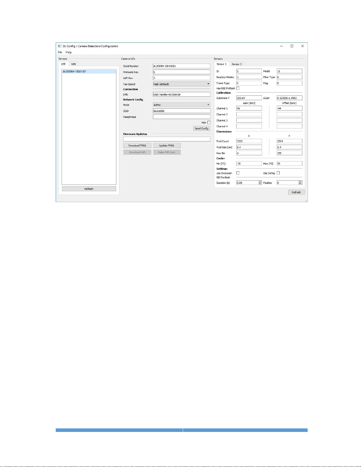
ALUMA USER’S MANUAL
49
To update the camera firmware, proceed as follows:
1. Start the DL Config utility program on your computer and connect to the
camera you want to update. It will display the current firmware version and
inform you if it is up-to-date or not.
2. If your firmware version is current, you can exit the utility.
3. If your firmware version is not current, click Download FPGA to have the
utility automatically download the latest version of the camera's firmware
that your driver will support. Wait for the program to report that the
download to your computer is complete.
4. Click Upload FPGA to have the utility upload the newly-downloaded version
of the firmware to the camera. This will take a few minutes. Wait for the
process to complete, then power cycle the camera, and reconnect to it.
5. If the procedure fails, the camera may revert back to the original firmware
that was programmed at the factory. If that happens, simply make sure
you have a solid connection to the camera and retry this procedure.
Once the main firmware has been successfully updated, you may resume
normal camera operations.

ALUMA USER’S MANUAL
50
To update the WiFi communications processor firmware, proceed as
follows:
You will need a micro SD card (not supplied) to perform this procedure. The DL
Config utility will retrieve the latest firmware from the website and write it to
that micro SD card. Follow the instructions provided by the utility.
1. Ensure that your camera is not powered and its micro SD slot is empty.
2. Start the DL Config utility and click Download WiFi. A large download will
begin and the utility will notify you when it is complete.
3. Insert the micro SD card into your computer and click Make WiFi Card.
4. Select the SD card drive letter in the popup dialog's drop-down menu and
click OK.
5. Wait for the operation to complete then eject the micro SD card when
prompted.
6. Insert the micro SD card into the camera and power it up. The firmware
update on the card will automatically be written to the camera.
7. The program will display a 2-minute timer. When two minutes has elapsed,
it will check whether the camera is live via WiFi. It will then inform you
whether the firmware update succeeded or it will display an error message.
8. If the procedure succeeded, remove the micro SD card from the camera. If
you forget to do this, the firmware will be reprogrammed from the card
every time you power up the camera. Power off the camera before removing
the micro SD card to ensure that the camera reboots cleanly.
9. If the procedure failed, the WiFi processor will not function properly. If that
happens, the camera will not appear on your WiFi network. However,
before retrying the procedure, be sure to wait a minute for your camera to
initialize and find the network. If it still does not appear on the network,
then repeat this procedure.
Once the WiFi firmware has been successfully updated, you may resume
normal camera operations.

ALUMA USER’S MANUAL
51
Appendix D: WiFi Connectivity
The ALUMA camera can optionally be operated using WiFi connectivity either
through an existing WiFi network or with the camera acting as an independent
WiFi hotspot. We advise connecting to your camera via USB first, so you can
customize your network connection details via a guaranteed connection.
1. To modify the network configuration, open DL Config (either the standalone
utility or in MaxIm LT) and consult the Network Config section of the form.
2. The Mode dropdown menu contains the security/connection mode of the
camera. The default mode is hotspot operation and is called the Ad Hoc.
This has the ALUMA create an Ad Hoc WiFi network that you can connect
to directly. The camera will appear on your computer or device as an
available network named Aluma888. No password is required. Connect to
this network in the usual manner for your device. The other options under
the dropdown menu are Unsecured, WPA, WPA2, and WEP.
3. Alternatively, the camera can be configured to log into a WiFi network by
using the DL Config standalone utility or from within MaxIm LT. You must
supply the network SSID, passphrase, and encryption type when prompted.
You can also choose to use the USA/Canada mode (which limits the
number of used channels) and allows the passphrase to be a hex key.
NOTE:
SSID is the name of the wireless network to connect to (in unsecured,
WPA, WPA2, WEP mode), or that the ALUMA generates in Ad Hoc mode.
Passphrase is the passphrase to use when connecting to a secured
network.
Hex allows the user to enter a hex passphrase for use with secured
networks.
4. The camera can be reset to the default hotspot mode by using a paperclip
to press the Reset switch. The switch is located through a small opening
beside the WiFi antenna. With the camera powered on, insert the paperclip
into the opening to push the switch.
Resetting to hotspot mode is required if you change your network password
or if you move your camera into another network area. Once it is reset, you
can reprogram the camera to connect to the new network or continue using
it as a hotspot.

ALUMA USER’S MANUAL
52
Appendix E: Troubleshooting
If you experience problems with the ALUMA camera operations, check the
following areas:
Check power:
The LED on the camera indicates power input levels as follows:
• RED when the voltage is very low. Check cable connections and the
condition of the power supply, especially if you are using a portable
(battery) source.
• AMBER when the power input is low. Check the condition of the power
supply, especially if you are using a portable (battery) source.
• GREEN when the power input is good.
The LED turns off whenever exposures are in progress.
Refer to Appendix A-2 for detailed information on the camera LED behavior.
Check the USB interface:
Follow these recommendations to ensure good USB connectivity:
• Use only good quality USB cables.
• Avoid using a USB hub if possible. If you do need a hub, try to avoid
putting two cameras on the same hub.
• If you are operating in outdoor ambient temperatures, be aware that
commercial-quality hubs often do not work well in freezing
temperatures. You should use an industrial-quality USB hub in such
conditions.
• Avoid using front panel USB jacks on desktop computers. They have
internal wiring that will degrade USB signal quality.
• Diffraction Limited suggests tie wrapping the USB cable and power
cable together near the camera in order to minimize risk of the USB
connector coming loose or being pulling out.
Check the WiFi interface:
Follow these recommendations to ensure proper WiFi connectivity:
• Confirm that you have selected WiFi when configuring the Connect To
drop-down item in Section 2.1.
• Ensure that you have sufficient WiFi signal strength. You can check this
with your smartphone or tablet.
• The camera requires approximately 30 seconds to boot up and connect
to WiFi, during which time the LED will be blinking. If the LED is on
steadily and you still cannot connect, plug in the USB cable and make
sure that the network parameters you supplied (SSID and password) are
correct.

ALUMA USER’S MANUAL
53
Note also that the following WiFi encryption modes are supported:
o Open (no password)
o WEP
o WPA
o WPA2
• Virtual network interfaces and adapter bridges can mask UDP broadcast
messages and block WiFi operation. If you can't discover your camera
despite the connection details being correct, try disabling the interfaces
and bridges one by one until only your physical adapters remain.

ALUMA USER’S MANUAL
54
Appendix F: Technical and Warranty Support
Software Downloads
Downloads are included on the Diffraction Limited website product pages:
http://diffractionlimited.com/
Navigate to your product and click the Downloads tab. Software utilities,
drivers, user documentation, and a Software Development Kit are available
here.
Technical Support
Technical Support: http://forum.diffractionlimited.com/
Technical Support Phone: (613) 225-2732
Authorized Repair Center
Bill Lynch – SBIG Service & Repair Center
3769 Constellation Road, Unit D
Lompoc, CA 93436
Bill Lynch – email via:
http://diffractionlimited.com/about-us/contact-us/#contact-form
NOTE: You must contact our authorized service & repair center for an RMA
number prior to returning your equipment.
Phone: (805) 308-6979
Diffraction Limited Main Address
For non-repair purposes & enquiries only:
Diffraction Limited
59 Grenfell Crescent, Unit B
Ottawa, ON K2G 0G3, Canada

ALUMA USER’S MANUAL
55
Appendix G: Compatible software products
MaxIm LT
MaxIm LT is a limited version of MaxIm DL, and is specifically for controlling
the ALUMA series cameras and other Diffraction Limited cameras and
autoguiders that use Gen 2 USB drivers. A license is available at no cost to the
original owner of the camera. The program can operate on Windows computers
only.
Please refer to the Windows Installation section in this guide for details.
MaxIm DL
MaxIm DL is a full-featured camera control and processing program available
from Diffraction Limited. It can control all Diffraction Limited cameras and
most third-party CCD camera models. ALUMA camera control requires Version
6.17 or higher.
Please note that a discount is available for MaxIm LT license owners.
ASCOM
The ALUMA cameras and filter wheels include fully-documented and supported
drivers for all platforms, including ASCOM drivers. ASCOM is in turn, is a
standard supported in a wide variety of third-party software.

ALUMA USER’S MANUAL
56
Appendix H: Concepts and Terminology
Anti-blooming Gate - When a sensor’s pixel has reached its full well capacity,
electrons can effectively spill over into an adjoining pixel. This is referred to as
blooming. Sensors with the anti-blooming option can be used to help stop or at
least reduce blooming when the brighter parts of an image saturate.
Astrometry - Astrometry is the study of stellar positions with respect to a
given coordinate system.
Autoguider - An autoguider a secondary camera that operates alongside the
main imaging camera. Its function is to take a continual stream of short
duration exposures of the sky that contains a suitably bright guide star. These
images are used to monitor if the selected star moves at all. If it does, then
signals are sent to the telescope mount to correct for small drive errors and
long-term pointing drift. This ensures that stars in the main image remain
stationery and perfectly round.
CCD - A CCD (Charged Coupled Device) sensor is a flat, two dimensional array
of very small light detectors referred to as pixels. Each pixel acts like a bucket
for electrons. The electrons are created by photons (light) absorbed in the pixel.
During an exposure, each pixel fills up with electrons in proportion to the
amount of light entering the pixel. After the exposure is complete, the electron
charge for each pixel is shifted one at a time to an amplifier in one corner of
the chip. The resulting voltage is transferred to an external amplifier, filter, and
digital converter. When a pixel is displayed at the computer screen, its
displayed brightness is proportional to the number of electrons that had
accumulated in the pixel during the exposure.
CMOS - A CMOS (Complementary Metal-Oxide Semiconductor) sensor is a flat,
two dimensional array of very small light detectors referred to as pixels. Each
pixel acts like a bucket for electrons. The electrons are created by photons
(light) absorbed in the pixel. During an exposure, each pixel fills up with
electrons in proportion to the amount of light entering the pixel. After the
exposure is complete, the electron charge at each pixel is amplified and
converted to a voltage by a tiny circuit at the pixel. The voltages from each
pixel are read out by built-in digital converters, often with one converter per
column, and the brightness values are read out from the sensor via a highspeed digital interface. When a pixel is displayed at the computer screen, its
displayed brightness is proportional to the number of electrons that had
accumulated in the pixel during the exposure.
Color imaging with a monochrome camera - One-shot Color (OSC) cameras
with a built-in Bayer matrix are handy for shooting quick color pictures
However, imaging with a monochrome camera provides the best quality,
sensitivity, and resolution.
A filter wheel with appropriate filters is used to create color images using a
monochrome camera. The simplest method is to use three filters, one for Red,
Green and Blue. Once the three images are captured, calibrated, aligned and
stacked, it is very simple to create the color composite image. That is because

ALUMA USER’S MANUAL
57
images are normally stored as three red, green, and blue planes. Your
computer monitor simply displays the three colors directly and your brain
interprets different combinations of those three colors as a full gamut of
different colors. It works because the retina in the human eye itself is based on
red, green, and blue light-sensitive cells.
Dark Frame - A Dark frame is an image taken completely in the dark. The
camera shutter must cover the sensor or the optical system must be capped to
prevent any light from reaching the sensor. Dark frames are subtracted from
normal exposures (light frames) to eliminate fixed pattern and dark current
noise from the image. Dark frames must typically be of the same integration
time and temperature as the light frame being processed.
Dark Current –Dark Current is the result of thermally-generated electrons
building up in the sensor’s pixels during an exposure. The number of electrons
due to Dark Current is related to two parameters, namely the integration time
(exposure length) and the temperature of the sensor. The longer the integration
time, the greater the dark current buildup. Conversely, the lower the operating
temperature, the lower the dark current. This is why the sensor is cooled for
long integration times. Dark Current is a mostly repeatable noise source,
therefore it can be subtracted from the image by taking a Dark Frame exposure
and subtracting it from the light image.
Dark Noise - Dark Noise is Poisson shot noise from the Dark Current. It
results from exactly the same process and statics as photon shot noise, just
with thermal electrons instead of photo electrons. Hot pixels are noisier due to
higher Dark Noise, and that noise is not subtracted when you subtract a Dark
Frame.
Double-Correlated Sampling – Double-Correlated Sampling (DCS) is a
technique employed to lower the digitization errors due to residual charge in
the readout capacitors of the camera. This results in lower readout noise.
False Color - False Color images are images that have had colors assigned to
different intensities instead of gray levels.
FITS Image File Format – The FITS image file format (which stands for
Flexible Image Transport System) is a common format supported by
astronomical image processing programs. MaxIm LT can save and read image
files in this format.
Flat Field - A Flat Field is an image with a uniform distribution of light
entering the optical system. An image taken this way is called a flat field image
and is used to correct images for vignetting and minor obscurations caused by
dust particles on the sensor or camera window. It also corrects pixel-to-pixel
variations in light sensitivity within the sensor.
Focal Reducer - A focal reducer reduces the effective focal length of an optical
system, and thereby provides a larger field of view to the camera sensor. While
this reduces image resolution, it also decreases exposure times since it
decreases the system’s effective focal ratio. It consists of a lens mounted in a
cell and is usually placed in front of an eyepiece or camera. Focal reducers are
often used in electronic imaging.

ALUMA USER’S MANUAL
58
Full Well Capacity - Full Well Capacity refers to the maximum number of
electrons that a sensor’s pixel can hold. This number is usually directly
proportional to the area of the pixel.
Histogram – A histogram is a simple bar graph that shows the range of
brightness in an image. Each bar in the graph represents a range of
brightness. The leftmost bar represents the dimmest pixels, and the rightmost
bar is for the brightest pixels. The height of the bar is the total number of
pixels in that particular brightness range of the image. Every image has a
different histogram depending on how much of the image is bright or dark.
A typical histogram will have a peak that shows the most common brightness
in the image. For astronomical images this is often the sky background.
Interline Transfer CCD –This is a CCD sensor with an architecture that
masks alternate columns of the sensor for storage. This requires a shift of only
one pixel to occur to transfer information from the active image area to the
storage area and permits extremely short shutter times. It also virtually
eliminates any image smear, also known as “blooming”. Some designs add
microlenses on the sensor surface to direct light from the masked columns into
the active imaging columns and thereby increase the overall sensitivity of the
sensor.
Light Frame - A Light Frame is the image of an object or scene before a Dark
Frame has been subtracted.
Photometry - In astronomical applications, photometry is the measurement of
the flux or intensity of an object's radiation. Typically this measurement is
performed in defined wavelength bands to facilitate comparison and analysis
Pixel Size - The smallest resolution element of an electronic camera sensor is
the pixel. Its size is usually specified in microns, such as the ALUMA 8300’s
5.40 micron pixels. The term is a contraction derived from “picture element”.
Quantum Efficiency - Quantum Efficiency (QE) refers to the fractional
number of electrons formed in a sensor pixel for a given number of impinging
photons. Quantum Efficiency is usually plotted as a function of wavelength.
Readout Noise - Readout noise is a combination of various noise sources
within the sensor plus a small contribution from the camera readout
electronics. Sources of noise include reset noise, Johnson noise, thermal
noise, and flicker noise.
Resolution and binning - The resolution of a camera sensor is determined by
its pixel size. Pixel size can be increased by combining or “binning” more than
one pixel and displaying the combined light received as a single pixel. Doing so
decreases the effective resolution but increases relative sensitivity. It also
shortens the image download time. Maximum absolute resolution is
determined by the size of an individual unbinned pixel and the characteristics
of the optical system you are using.

ALUMA USER’S MANUAL
59
Saturation - Saturation refers to the full well capacity of a sensor’s pixel as
well as the maximum counts available in the A/D converter. A pixel is said to
be saturated when the number of electrons accumulated in the pixel reaches
its full well capacity. The A/D converter is saturated when the input voltage
exceeds the maximum permissible.
Sky Background - The sky background illumination or brightness is the
number of counts in an image in areas free of stars or nebulosity and is due to
primarily to city lights and natural sky glow. High levels of sky background can
increase the noise in images just like dark current. For some objects, filters
can be used to reduce the sky background level.
Seeing - Seeing in the astronomical sense refers to the steadiness of the
atmosphere during an observing or imaging session. Poor seeing is caused by
air mass turbulence and atmospheric temperature variations. Seeing quality is
often determined by measuring the Full Width Half Maximum (FWHM)
diameter of recorded star images. Refer also to “Transparency”.
TE Cooler - A TE cooler is a thermal electric cooling device used to cool the
camera sensor down to a low operating temperature. Every camera sensor
produces a certain amount of dark current, which accumulates in the pixels
during an exposure. This unwanted dark current is produced by heat, and
high-performance cameras such as the ALUMA series cool their sensors to
minimize this effect. The sensor is mounted to the TE cooler, which in turn, is
mounted to a heat sink, usually the camera head housing. A TE cooler is also
often referred to as a Peltier cooler.
TIFF Image File Format - The TIFF image file format (which stands for Tagged
Interchange File Format) was developed jointly by Microsoft and Aldus
Corporations to allow easy interchange of graphics images between programs
in areas such as presentation and desktop publishing. MaxIm LT can save and
read image files in this format.
Transparency – Transparency in the astronomical sense refers to the total
transparency of the atmosphere from the ground to the edge of space. It is
largely dependent on the amount of water vapor in the air, but not entirely
analogous to the amount of the cloud cover present in a location. There can be
isolated clouds in a finely transparent air mass, and conversely, poor
transparency can occur when there is little or no cloud present. Man-made
light pollution and aerosols (i.e. industrial pollutants, volcanic ash, pollen, sea
salt, and forest fire smoke) also degrade transparency. Refer also to “Seeing”.
Tri-Color - Tri-Color refers to color images created using three different colors
mixed into a balanced color image using red, green and blue filters. An object
is imaged three times, once with each color filter. The three images are then
co-added and color balanced using appropriate software, such as MaxIm LT.
Vignetting - Vignetting is the obstruction of portions of the incoming light
path by parts of an optical system. It usually occurs in the off-axis portions of
the image and is seen as an uneven illumination of the image plane. When
imaging using a vignetted optical system, the corners of the camera sensor will
receive less light. This can be compensated for by using flat-fielding
calibration, but it is usually preferable to physically avoid vignetting if possible.

ALUMA USER’S MANUAL
60
 Loading...